


YOU'RE HEARD, LOUD AND CLEAR.
Installation and Operation Manual for Compact Tower-Top Amplifier System Models 429-83H-01-M/T
and 429-83H-01-M-48
Manual Part Number
7-9439
8625 Industrial Parkway, Angola, NY 14006 Tel: 716-549-4700 Fax: 716-549-4772 sales@birdrf.com www.bird-technologies.com

Warranty
This warranty applies for one year from shipping date.
TX RX Systems Inc. warrants its products to be free from defect in material and workmanship at the time of shipment. Our obligation under warranty is limited to replacement or repair, at our option, of any such products that shall have been defective at the time of manufacture. TX RX Systems Inc. reserves the right to replace with merchandise of equal performance although not identical in every way to that originally sold. TX RX Systems Inc. is not liable for damage caused by lightning or other natural disasters. No product will be accepted for repair or replacement without our prior written approval. The purchaser must prepay all shipping charges on returned products. TX RX Systems Inc. shall in no event be liable for consequential damages, installation costs or expense of any nature resulting from the purchase or use of products, whether or not they are used in accordance with instructions. This warranty is in lieu of all other warranties, either expressed or implied, including any implied warranty or merchantability of fitness. No representative is authorized to assume for TX RX Systems Inc. any other liability or warranty than set forth above in connection with our products or services.
TERMS AND CONDITIONS OF SALE
PRICES AND TERMS:
Prices are FOB seller’s plant in Angola, NY domestic packaging only, and are subject to change without notice. Federal, State and local sales or excise taxes are not included in prices. When Net 30 terms are applicable, payment is due within 30 days of invoice date. All orders are subject to a $100.00 net minimum.
QUOTATIONS:
Only written quotations are valid.
ACCEPTANCE OF ORDERS:
Acceptance of orders is valid only when so acknowledged in writing by the seller.
SHIPPING:
Unless otherwise agreed at the time the order is placed, seller reserves the right to make partial shipments for which payment shall be made in accordance with seller’s stated terms. Shipments are made with transportation charges collect unless otherwise specified by the buyer. Seller’s best judgement will be used in routing, except that buyer’s routing is used where practicable. The seller is not responsible for selection of most economical or timeliest routing.
CLAIMS:
All claims for damage or loss in transit must be made promptly by the buyer against the carrier. All claims for shortages must be made within 30 days after date of shipment of material from the seller’s plant.
SPECIFICATION CHANGES OR MODIFICATIONS:
All designs and specifications of seller’s products are subject to change without notice provided the changes or modifications do not affect performance.
RETURN MATERIAL:
Product or material may be returned for credit only after written authorization from the seller, as to which seller shall have sole discretion. In the event of such authorization, credit given shall not exceed 80 percent of the original purchase. In no case will Seller authorize return of material more than 90 days after shipment from Seller’s plant. Credit for returned material is issued by the Seller only to the original purchaser.
ORDER CANCELLATION OR ALTERATION:
Cancellation or alteration of acknowledged orders by the buyer will be accepted only on terms that protect the seller against loss.
NON WARRANTY REPAIRS AND RETURN WORK:
Consult seller’s plant for pricing. Buyer must prepay all transportation charges to seller’s plant. Standard shipping policy set forth above shall apply with respect to return shipment from TX RX Systems Inc. to buyer.
DISCLAIMER
Product part numbering in photographs and drawings is accurate at time of printing. Part number labels on TX RX products supersede part numbers given within this manual. Information is subject to change without notice.
Bird Technologies Group |
TX RX Systems Inc. |

Manual Part Number 7-9439
Copyright © 2009 TX RX Systems, Inc.
First Printing: June 2007
Version Number |
Version Date |
|
|
1 |
06/08/07 |
|
|
2 |
08/17/07 |
|
|
3 |
10/10/07 |
|
|
4 |
02/08/08 |
|
|
5 |
10/24/08 |
|
|
6 |
09/03/09 |
|
|
|
|
|
|
|
|
Symbols Commonly Used
WARNING |
ESD Electrostatic Discharge |
CAUTION or ATTENTION |
Hot Surface |
High Voltage |
Electrical Shock Hazard |
NOTE
Heavy Lifting |
Important Information |
Bird Technologies Group |
TX RX Systems Inc. |

Changes to this Manual
We have made every effort to ensure this manual is accurate. If you discover any errors, or if you have suggestions for improving this manual, please send your comments to our Angola, New York facility to the attention of the Technical Publications Department. This manual may be periodically updated. When inquiring about updates to this manual refer to the manual part number and revision number on the revision page following the front cover.
Contact Information
Sales Support at 716-217-3113
Customer Service at 716-217-3144
Technical Publications at 716-549-4700 extension 5019
Bird Technologies Group |
TX RX Systems Inc. |
Table of Contents |
|
General Description ............................................................................................ |
1 |
Unpacking ............................................................................................................ |
4 |
Pre-Installation Checkout ................................................................................... |
4 |
Mechanical Inspection ....................................................................................... |
4 |
Initial Power-up Test ........................................................................................... |
5 |
Bench Testing ..................................................................................................... |
6 |
Installation............................................................................................................ |
8 |
Base to Tower-Top Communications ................................................................. |
8 |
Test Transmission Line ...................................................................................... |
9 |
Installing the System .......................................................................................... |
9 |
Installing the Tower-Top Box ............................................................................. |
9 |
In-building Lightning Arresters ............................................................................ |
9 |
Installing the MCU ............................................................................................ |
12 |
Interference and IM Considerations .................................................................. |
14 |
Feedline Data ..................................................................................................... |
14 |
Optimizing The System ..................................................................................... |
15 |
Attenuation Settings ......................................................................................... |
15 |
TTA Net Gain..................................................................................................... |
15 |
Receiver Multicoupler Distribution ..................................................................... |
15 |
Setting the TTA NET GAIN Attenuation ............................................................ |
16 |
Determining Needed Attenuation .................................................................... |
16 |
Setting Distribution Attenuation ......................................................................... |
17 |
Spectrum Analysis ............................................................................................ |
17 |
Procedure for Spectral Analysis...................................................................... |
19 |
Operational Tests (Sensitivity and Degradation) ........................................... |
19 |
Front Panel Test Port ........................................................................................ |
19 |
Tower Top Amplifier Inputs................................................................................ |
19 |
Static System Sensitivity ................................................................................... |
19 |
Measuring Static Sensitivity (Load Connected) ................................................. |
19 |
Effective System Sensitivity............................................................................... |
21 |
Measuring Effective Sensitivity (Antenna Connected)....................................... |
22 |
Degradation ....................................................................................................... |
23 |
Routine Operation ............................................................................................. |
23 |
Amplifier Monitoring ........................................................................................... |
23 |
LCD Display....................................................................................................... |
23 |
Current Draw ................................................................................................... |
23 |
Test Cable Connection .................................................................................... |
23 |
TTA Temperature ............................................................................................ |
23 |
Software Version ............................................................................................. |
23 |
Front Panel LEDs .............................................................................................. |
24 |
Form-C Contacts ............................................................................................... |
24 |
Alarms ................................................................................................................ |
24 |
The Test Mode ................................................................................................... |
24 |
Set LNA X Active ............................................................................................... |
24 |
Terminate LNA X ............................................................................................... |
25 |
Un-Terminate LNA X ......................................................................................... |
25 |
System Troubleshooting .................................................................................. |
25 |
Performance Degradation ................................................................................ |
25 |
Hardware Problems .......................................................................................... |
25 |
Lightning and Lightning Arresters ................................................................... |
26 |
Vandalism ....................................................................................................... |
26 |
AC Line Fuse (Model 429-83H-01-M) ............................................................... |
26 |
Table of Contents |
Manual 7-9439-6 |
09/03/09 |
Disconnected Cables ........................................................................................ |
26 |
Periodic Maintenance........................................................................................ |
27 |
Recommended Spare Parts .............................................................................. |
27 |
Optional Equipment .......................................................................................... |
27 |
Narrowband Filter .............................................................................................. |
27 |
Multicoupler Expansion Deck ............................................................................ |
28 |
Figures and Tables |
|
Figure 1: Front view of the tower-top box ............................................................ |
1 |
Figure 2A: Top view of the multicoupler unit (MCU) ............................................ |
2 |
Figure 2B: Front view of the MCU ....................................................................... |
2 |
Figure 2C: Back view of the MCU ....................................................................... |
2 |
Figure 3: Cable connections for system components .......................................... |
4 |
Figure 4: Initial power-up test ............................................................................... |
5 |
Figure 5: Boot-up sequence ................................................................................. |
6 |
Figure 6: Default display ....................................................................................... |
6 |
Figure 7: Menu selections .................................................................................... |
7 |
Figure 8: Test equipment interconnection for “bench testing” ............................. |
8 |
Figure 9A: System installation guidelines .......................................................... |
10 |
Figure 9B: System installation guideline notes................................................... |
11 |
Figure 10: Tower-top box mechanical details ...................................................... |
9 |
Figure 11: Application of rubber splicing tape ................................................... |
12 |
Figure 12: Lightning Arrester .............................................................................. |
12 |
Figure 13: Optional Data Network Protector....................................................... |
13 |
Figure 14: Alarm terminals ................................................................................ |
14 |
Figure 15: Testing the output spectrum ............................................................. |
18 |
Figure 16: Maximum signal level mask ............................................................. |
18 |
Figure 17: Calculating actual sensitivity ............................................................. |
20 |
Figure 18: Measuring sensitivity through the test port ....................................... |
21 |
Figure 19: Optional filter interconnect diagram .................................................. |
28 |
Figure 20: Optional multicoupler expansion deck .............................................. |
28 |
Table 1: System Specifications ............................................................................. |
1 |
Table 2: Tower Box Specifications......................................................................... |
3 |
Table 3: Multicoupling Unit Specifications............................................................. |
3 |
Table 4: Bench Test Results.................................................................................. |
6 |
Table 5: Optimum Total TTA NET GAIN .............................................................. |
16 |
Table 6: Distribution Attenuation Settings ........................................................... |
17 |
Table 7: Amplifier Status Troubleshooting Guide ................................................ |
22 |
Table 8: Typical Current Readings ...................................................................... |
23 |
Table 9: Loss of Sensitivity Troubleshooting Guide ............................................ |
26 |
Table 10: Disconnected Cables .......................................................................... |
27 |
Table 11: Optional Narrowband Filters................................................................ |
27 |
Table of Contents |
Manual 7-9439-6 |
09/03/09 |
Appendixes |
|
Appendix A: Front Panel Ethernet Connectivity ................................................. |
29 |
Ethernet Connectivity .......................................................................................... |
29 |
Direct Connection .............................................................................................. |
29 |
Required Equipment ........................................................................................ |
29 |
Procedure ........................................................................................................ |
29 |
Networked Connection ...................................................................................... |
30 |
Required Equipment ........................................................................................ |
32 |
Procedure ........................................................................................................ |
32 |
TTA Network Port Security ................................................................................ |
34 |
Data Encryption ............................................................................................... |
34 |
SNMP Support Disabled.................................................................................. |
34 |
Telnet Security ................................................................................................. |
34 |
Changing the Telnet Port Password................................................................... |
35 |
Appendix B: Changing your Service Computer IP Address ............................... |
36 |
Table of Contents |
Manual 7-9439-6 |
09/03/09 |

Table of Contents |
Manual 7-9439-6 |
09/03/09 |
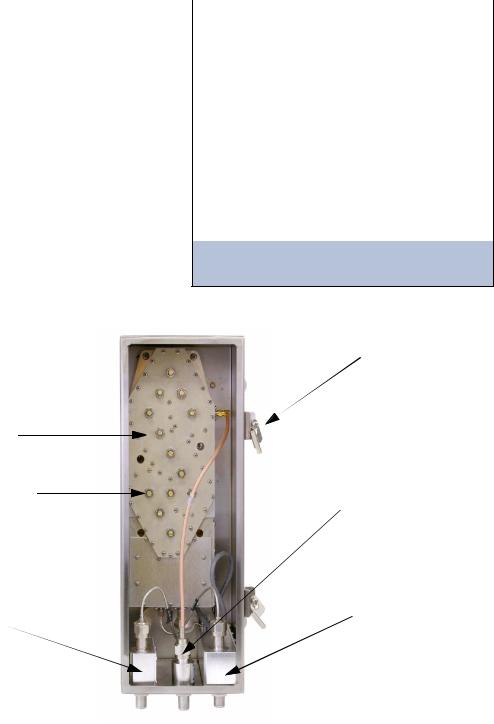
GENERAL DESCRIPTION
Your TXRX Systems Inc. Tower Top Amplifier System provides the highest degree of reliability available in a Tower Top Amplifier (TTA). The system uses quadrature-coupled amplifiers (also called balanced amplifiers) to create a redundant amplifier configuration in both the tower box and the receiver multicoupling unit (MCU). Each quadamplifier provides two simultaneously used, essentially parallel paths of amplification. Failure of one of these paths of amplification results in an overall gain reduction of only 6 dB.
The system also supplies automatic backup-ampli- fier switching in the tower top box. Fault detection circuitry continuously monitors the DC power operation of the primary quad-amplifier and automatically switches to the identical secondary quadamplifier if conditions indicate a primary malfunction. If the secondary quad-amplifier malfunctions, operation switches to whichever quad-amplifier is still providing some gain due to operation of one of its amplification paths. Fault detection circuitry also
Amplifier / Filter
Assembly
3-21548
Tuning Screw
DO NOT ADJUST
Surge
Suppressor 
8-21514
provides at-a-glance status reporting, with frontpanel LED’s and an LCD display. The system specifications for the tower top amplifier are listed in Table 1.
Parameter |
Specification |
|
|
Bandwidth |
792 - 824 MHz |
|
|
Noise Figure |
2.9 dB typ, 3.5 dB max |
|
|
3rd order IIP |
> 15.0 dBm |
|
|
TTA Net Gain |
Fully settable by |
|
electronic attenuator |
|
|
Rejection |
110 dB Min, 120 db Nom |
|
@776 and 851 MHz |
|
|
AC Current |
|
(model 429-83H-01-M) |
340 mA (typ) @120 VAC |
|
|
DC Current |
|
(model 429-83H-01-M-48) |
780 mA (typ) @ 48 VDC |
|
|
Table 1: System specifications.
13 dB TTA Net Gain and
maximum 6 dB transmission line loss assumed
Door
Clamp
Surge
Suppressor
8-21183
Surge
Suppressor
8-21549
Figure 1: Front view of the tower-top box (door removed for clarity).
TX RX Systems Inc. |
Manual 7-9439-6 |
09/03/09 |
Page 1 |

3-21453 |
8-21515 Power Supply (model 429-83H-01-M) |
3-21476 |
|
Front Panel Board |
3-21516 DC-DC Converter (model 429-83H-01-M-48) |
Front Ethernet Board |
|
(under shroud) |
|
|
(under shroud) |
|
|
||
3-21450 |
|
|
|
Distribution Amp |
|
|
|
3-21496  Rear Panel
Board
3-18173 |
3-18171 |
3-18171 |
4-Way Divider |
8-Way Divider |
8-Way Divider |
Figure 2A: Top view of the Multicoupling Unit (MCU). Model 429-83H-01-M shown.
LAN Port |
Status LED’s |
Contrast |
Up |
Cancel |
|||
Adjust |
Button |
Button |
|||||
|
|||||||
|
|
|
|||||
|
|
|
|||||
|
|
|
|
|
|
|
|
|
|
|
|
|
|
|
|
|
|
|
|
|
|
|
|
Amplifier Select |
Display |
Down |
Enter |
Test |
Buttons |
|
Button |
Button |
Port |
Figure 2B: Front view of the MCU. Model 429-83H-01-M shown.
Ground |
|
To additional 8-way dividers |
||
|
|
|
|
|
|
Test |
Transmission |
on optional expansion deck. |
|
|
Terminate when unused. |
|||
|
cable |
cable |
||
|
|
|||
|
|
|
|
|
|
|
|
|
|
CAT-5 |
|
|
|
|
|
|
|
|
|
||
Cable |
|
Alarm |
|||
Terminals |
|||||
here |
|||||
|
|
|
|
||
|
|
|
|
|
|
AC or DC Cord
(model dependent)
To station receivers |
To station receivers |
Unused ports do not |
Unused ports do not |
|
|
require termination |
require termination |
|
Figure 2C: Back view of the MCU. Model 429-83H-01-M shown.
TX RX Systems Inc. |
Manual 7-9439-6 |
09/03/09 |
Page 2 |
The quad-amplifier in the tower top box amplifies the weak received signal before the signal enters a long and lossy transmission line, thus preventing the line loss from degrading the signal-to-noise ratio. The quadrature amplifiers have a separate power circuit for each half of the amplifier which provides component redundancy as well as unsurpassed IM performance. Microprocessor controlled fault detection circuitry in the tower top box provides continuous monitoring and switching of each quad amplifier while sending operational data to the base unit front panel for at-a-glance status reporting and form-C contact switching for alarm integration. Included in the tower top box is a pre-
Electrical Specifications
Frequency Range |
792 to 824 MHz |
|
|
Net Gain |
23 dB |
|
|
Noise Figure (typ /max) |
2.7 / 3.0 dB |
|
|
Backup Amplifier Switching |
Solid State RF Switch |
|
|
Integrated Test Port |
45 dB |
Isolation |
|
|
|
Preselector Type |
7-pole TEM Bandpass |
|
with cross-couplings |
Loss |
<0.8 dB |
Rejection |
>60 dB @ 776 and 851 MHz |
|
|
LNA Type |
2-stage Quadrature |
|
integrated into filter |
Gain |
26 dB |
Noise Figure |
1.2 dB |
3rd Order Input IP |
18 dBm |
|
|
Impedance |
50 Ohms |
|
|
Antenna Port VSWR |
2 : 1 |
|
|
Power Requirements |
12 VDC @ 1.25 A |
|
|
Lightning Protection |
Impulse Suppressor on all |
|
external connectors |
|
|
Operating Temp Range |
-30°C to +60°C |
|
|
|
|
Mechanical Specifications |
|
|
|
Enclosure |
Modified NEMA 4x: |
|
Stainless steel |
|
weather resistant |
|
|
Connectors |
N -female |
|
|
Dimensions (HWD) |
18” x 6” x 6” |
not including mounting tabs |
(457 x 152 x 152 mm) |
and connectors |
|
|
|
Net Weight |
20 lbs (9.1 kg) |
|
|
Table 2: Tower box specifications. Values are typical unless noted otherwise.
selector filter, amplifier “A” and amplifier “B,” switching circuitry, control board and PolyPhaser surge suppressors (see Figure 1). The specifications for the tower box are listed in Table 2.
The ground-mounted MCU shown in Figures 2A through 2C is intended for 19-inch rack mounting. It houses amplifier and signal distribution assemblies, alarm indicators, a power supply or DC-DC
Electrical Specifications
Frequency Range |
792 to 824 MHz |
|
|
Multicoupler Net Gain |
+1 dB typ; 0 dB min |
|
|
Distribution Amp Type |
Quad-Coupled dual stage |
Gain |
23 dB |
Noise Figure |
4 dB |
1 dB compression point |
27 dBm |
3rd Order Output IP |
46 dBm |
|
|
Number of Outputs |
16 or 32 |
Split Loss |
18 dB |
|
|
Impedance |
50 Ohms |
|
|
VSWR |
<2 : 1 |
|
|
Connectors |
|
to TTA |
N - Female |
to BTS |
BNC - Female |
Test Port input |
BNC - Female |
|
|
TTA NET GAIN |
0 to 15.5 dB |
electronic attenuator |
in 0.5 dB steps |
|
|
DISTRIBUTION |
0 to 3 db |
electronic attenuator |
in 0.5 dB steps |
|
|
Alarm / Warning Contacts |
Two Form-C Contacts |
|
Nominal 2A @ 30 VDC |
|
or 0.5A @125 VAC |
|
|
I/O |
Ethernet |
|
|
Power Requirements |
|
Model 429-83H-01-M |
90 - 240 Vac @ 50/60 Hz |
Model 429-83H-01-M-48 |
-48VDC |
|
|
Operating Temp Range |
0°C to + 50°C |
|
|
|
|
Mechanical Specifications |
|
|
|
Enclosure |
Standard EIA 19” Rack Mount |
|
|
Dimensions (HWD) |
1 RU x 19” x 14” |
|
(38 x 483 x 356 mm) |
|
|
Net Weight |
10.5 lbs (4.8 kg) |
|
|
Table 3: Multicoupling Unit specifications. Values are typical unless noted otherwise.
TX RX Systems Inc. |
Manual 7-9439-6 |
09/03/09 |
Page 3 |

converter, and a display panel to provide visual feedback on the system’s operating status. The specifications for the MCU are listed in Table 3. Also included in the system is a webpage user interface for controlling and monitoring of amplifier currents, alarms, and attenuators. The webpage user interface is accessed through the front panel LAN connector. Refer to Appendix A for instructions on accessing this feature.
UNPACKING
Each major component of the TTA system is individually packaged and shipped via motor freight or UPS. It is important to report any visible damage to the carrier immediately. It is the customer's responsibility to file damage claims with the carrier within a short period of time after delivery (1 to 5 days).
PRE-INSTALLATION CHECKOUT
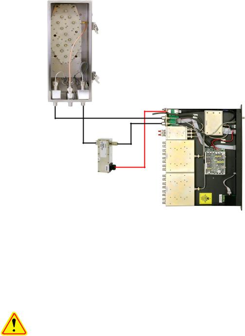
The following pre-installation tests should be performed after unpacking the system to verify nothing has loosened during transit. Additionally, the system should be made operational on the bench with all components at ground level to verify proper electrical performance. Figure 3 illustrates all of the cable connection points for both the tower top box and the MCU.
The tower top box should NOT be NOTE installed on the tower until all of the  pre-installation tests are successfully
completed.
Mechanical Inspection
Open the tower top box by loosening all the doorclamp locking screws and rotating the clamps to
Tower Top Box
To |
To |
|
Station Receivers |
Station Receivers |
|
Test |
|
|
Port Trans |
|
|
To |
|
|
120 |
MCU |
|
VAC |
||
|
||
Main |
|
CAT-5e Cable
Lightning Arrester |
Test |
|
|
Main |
Port |
|
|
Transmission |
|
TX RX part no.8-21550 |
|
|
||
Test |
|
|
|
|
|
|
|
|
|
|
|
|
|
|
|
Main |
|
|
|
|
|
|
|
|
|
|
Antenna |
||
Figure 3: Cable connections for system components. Model 429-83H-01-M shown.
TX RX Systems Inc. |
Manual 7-9439-6 |
09/03/09 |
Page 4 |
Tower Top Box
Test Ant |
Main |
Front
Panel
Test
Port
CAT-5e |
|
Cable |
|
Lightning Arrester |
|
TX RX part no. 8-21550 |
MCU |
Figure 4: Initial power-up test.
release the door. Make sure that all of the connectors are tight. In addition, it is advisable to check the tightness of the hold-down screws for the various assemblies to insure nothing loosened during shipment. Likewise, check all of the cable connections on the MCU to insure they are all properly mated to their associated plugs.
CAUTION: The wide band filter in the tower top box is factory tuned and must not be field adjusted. Field tuning of this filter is not required. Do not adjust the tuning slugs of the amplifier/filter assembly.
Initial Power-Up Test
To perform the initial power-up test the system should be temporarily interconnected at ground level using short cables. Figure 4 shows the tem-
porary equipment hookup for initial power-up testing.
Once the equipment is temporarily interconnected then power is applied to the system by plugging the MCU’s AC cord into a suitable AC outlet (model 429-83H-01-M) or connecting the DC power cable to a suitable -48 VDC supply (model 429-83H-01- M-48). The following start-up sequence occurs.
1)At turn-on, the three front panel status LED’s will all glow a steady red while the display panel shows a row of solid boxes on the top display line. This will last for about 10 seconds while the systems micro-controllers boot-up.
2)During the next 5 seconds the base unit (MCU) will establish communications with the tower box. The front panel status LED’s will occasionally flash green. The display panel will present the message “Connecting to Tower Controller” and then will briefly flash the MCU’s current software version. See Figure 5.
TX RX Systems Inc. |
Manual 7-9439-6 |
09/03/09 |
Page 5 |

Figure 5: MCU software version is displayed briefly during the boot-up sequence.
3)After the power-up sequencing is complete the screen should show the default display as shown in Figure 6. The status LED for each active amplifier will glow a steady green and the status LED for the inactive (stand-by) LNA will be dark.
Figure 6: Default display.
The tower top amplifier system is software directed so control of the system is accomplished via user interface with the front panel using the display screen and the four menu selection buttons. A flow chart showing all of the possible user menu selections is shown in Figure 7.
Bench Testing
The purpose of the bench test is to verify that all of the system components are working correctly and to measure the systems sensitivity before climbing the tower to mount the tower top box. One station receiver is selected and the test is performed at this frequency. Short temporary cables are used to interconnect all components. A SINAD meter is used for the test (or a bit error rate meter if required) along with a signal generator.
1)The stand-alone receiver sensitivity is measured and recorded first. Record the value in
Table 4.
2)Connect the equipment as shown in Figure 8. Be sure that the signal generator is setup for a 3 KHz deviation with a 1000 Hz tone (analog) or proper pattern for BER testing.
Test Performed |
Result |
|
|
Stand Alone |
|
Receiver |
|
Sensitivity |
dBm |
|
|
* Bench Test |
|
Static |
|
Sensitivity |
dBm |
|
|
Model Number |
|
(Tower Top Box) |
|
|
|
Serial Number |
|
(Tower Top Box) |
|
|
|
Table 4: Bench Test Results.
* Default “TTA NET GAIN“ Attenuation (3.0 dB) * Default “DISTRIBUTION” Attenuation (1.0 dB)
3)Measure and record the systems bench test static sensitivity in table 4. The sensitivity value will vary depending on the amount of internal programmable attenuation selected via software interface. The bench test measurement should be taken with the default values selected for “TTA NET GAIN” attenuation (3.0 dB) and “DISTRIBUTION” attenuation (1.0 dB). These are the factory default settings that are programmed into your system when you first turn it on.
4)Select the other tower top amplifier and check that the bench test static sensitivity value remains nearly the same. This will insure that both amplifiers in the tower top box are functioning properly. To select an alternate towertop amplifier press the associated amplifier select button on the front panel, the status LED will begin to flash, then press the ENTER button to finalize the selection.
5)If the tower box door is opened during the installation it is important to re-tighten the doorclamp locking screws uniformly so that the door gasket seal is maintained. Tighten each clamp about half-way, then start back at the first clamp and fully tighten each one in the same order. Tighten with a hand tool only. Insure that the moisture vent holes at the bottom of the box are unobstructed.
TX RX Systems Inc. |
Manual 7-9439-6 |
09/03/09 |
Page 6 |

429-83H-01-M Menu System
429-83H-01-M
TX RX SYSTEMS INC
LNA X ACTIVE
A CURRENT XXXmA
B CURRENT XXXmA
BASE CURRENT
XXXX mA
TEST CABLE
CONNECTED
NOT CONNECTED
TTA TEMPERATURE
+/- XX DEGREES C
BASE V X.XX
TOWER V X.XX
INITIALIZE
ENTER TO RESTART
TEST
ENTER TO SELECT
ATTENUATORS
ENTER TO SELECT
DEFAULT |
|
|
|
|
|
KEY |
|
|
|
|
|
|
|
|
|
|
|
|
|
|
|
|
|
|
|
|
|
|
|
||||||||||
DISPLAY |
|
|
|
|
|
|
|
|
|
|
|
|
|
|
|
|
|
|
|
|
|
|
|
|
|
|
|
|
|
|
|
|
|
|
|||||
|
|
|
|
|
|
|
|
|
|
|
|
|
|
|
|
|
|
|
|
|
|
|
|
|
|
|
|
|
|
|
|
|
|
||||||
|
|
|
|
|
|
|
|
|
|
|
|
|
|
|
|
|
|
|
|
|
|
|
|
|
|
|
|
|
|
|
|
|
|||||||
|
|
|
|
|
|
|
C |
|
PRESS CANCEL KEY |
|
|
|
|
|
|
|
|
|
|
|
|
|
|
|
|
|
|
|
|
|
|
|
|||||||
|
|
|
|
|
|
|
|
|
|
|
|
|
|
|
|
|
|
|
|
|
|
|
|
|
|
|
|
|
|||||||||||
|
|
|
|
|
|
|
E |
|
PRESS ENTER KEY |
|
|
|
|
|
|
|
|
|
|
|
|
|
|
|
|
|
|
|
|
|
|
|
|||||||
|
|
|
|
|
|
|
|
|
|
|
|
|
|
|
|
|
|
|
|
|
|
|
|
|
|
|
|
|
|
||||||||||
|
|
|
|
|
|
|
|
|
|
|
|
|
|
|
|
SET LNA A ACTIVE |
|
|
|
|
|||||||||||||||||||
|
|
|
|
|
|
|
|
|
|
|
|
|
|
|
|
|
|
|
|
|
|
|
|
|
|
|
|
|
|
|
|
|
|||||||
|
|
|
|
|
|
|
|
|
PRESS UP-ARROW KEY |
|
|
|
|
|
|
|
ENTER TO CONFIRM |
C |
|
|
|||||||||||||||||||
|
|
|
|
|
|
|
|
|
|
|
|
|
|
|
|
|
|||||||||||||||||||||||
|
|
|
|
|
|
|
|
|
|
|
|
|
|
|
|
|
|
|
|
|
|
|
|
|
|
|
|
|
|
|
|
|
|||||||
|
|
|
|
|
|
|
|
|
PRESS DOWN-ARROW KEY |
|
|
|
|
|
|
|
|
|
|
|
|
|
|
|
|
|
|
||||||||||||
|
|
|
|
|
|
|
|
|
|
|
|
|
|
|
|
|
|
|
|
|
|
|
|
|
|||||||||||||||
|
|
|
|
|
|
|
|
|
PRESS EITHER ARROW KEY |
|
|
|
|
|
|
|
|
|
|
|
|
|
|
|
|
|
|
||||||||||||
|
|
|
|
|
|
|
|
|
|
|
|
|
|
SET LNA B ACTIVE |
|
|
|
|
|||||||||||||||||||||
|
|
|
|
|
|
|
|
|
|
|
|
|
|
|
|
|
|
|
|
|
|
|
|
|
|
|
|
|
|
|
|
|
|||||||
|
|
|
|
|
|
|
|
|
YELLOW INDICATES |
|
|
|
|
|
|
|
|
|
|
|
|
ENTER TO CONFIRM |
C |
|
|
||||||||||||||
|
|
|
|
|
|
|
|
|
|
|
|
|
|
|
|
|
|
|
|
|
|
|
|||||||||||||||||
|
|
|
|
|
|
|
|
|
|
|
|
|
|
|
|
|
|
|
|
|
|
|
|
|
|||||||||||||||
|
|
|
|
|
|
|
|
|
RECORDABLE VALUE |
|
|
|
|
|
|
|
|
|
|
|
|
|
|
|
|
||||||||||||||
|
|
|
|
|
|
|
|
|
|
|
|
|
|
|
|
|
|
|
|
|
|
|
|
|
|
|
|
|
|
|
|
||||||||
|
|
|
|
|
|
|
|
|
|
|
|
|
|
|
|
|
|
|
|
|
|
|
|
|
|
|
|
|
|
|
|
|
|
|
|
|
|
|
|
|
|
|
|
|
|
|
|
|
|
|
|
|
|
|
|
|
|
|
|
|
|
|
|
|
|
|
|
|
|
|
|
|
|
|
|
|
|
|
|
|
|
|
|
|
|
|
|
|
|
|
|
|
|
|
|
|
|
|
|
|
|
|
|
|
|
|
|
|
TERMINATE LNA A |
|
|
|
|
||||||
|
|
|
|
|
|
|
AS AN EASY REFERENCE |
|
|
|
|
|
|
ENTER TO CONFIRM |
C |
|
|
||||||||||||||||||||||
|
|
|
|
|
|
|
|
|
|
|
|
|
|
|
|||||||||||||||||||||||||
|
|
|
|
|
|
|
|
|
|
|
|
|
|
|
|
|
|||||||||||||||||||||||
|
|
|
|
|
|
|
RECORD VALUES HERE |
|
|
|
|
|
|
|
|
|
|
||||||||||||||||||||||
|
|
|
|
|
|
|
|
|
|
|
|
|
|
|
|
|
|
|
|
|
|
|
|
||||||||||||||||
|
|
|
|
|
|
|
|
|
|
|
|
|
|
|
|
|
|
|
|
|
|||||||||||||||||||
|
|
|
|
|
|
|
|
|
|
|
|
|
|
|
|
|
|
|
|
|
|
|
|
|
|
|
|
|
|
|
|
|
|
|
|
|
|
|
|
|
|
|
|
TTA NET GAIN |
|
|
|
|
|
|
|
|
|
|
|
|
|
|
|
|
|
|
|
|
|
|
|
|
|
|
|
|
|
||||||
|
|
|
|
|
|
|
|
|
|
|
|
|
|
|
|
|
|
|
|
|
|
TERMINATE LNA B |
|
|
|
|
|||||||||||||
|
|
|
|
|
|
|
|
|
|
|
|
|
|
|
|
|
|
|
|
|
|
|
|
|
|
|
|
|
|
|
|
|
|||||||
|
|
|
|
DISTRIBUTION |
|
|
|
|
|
|
|
|
|
|
|
|
|
|
|
|
|
|
ENTER TO CONFIRM |
C |
|
|
|||||||||||||
|
|
|
|
|
|
|
|
|
|
|
|
|
|
|
|
|
|
|
|
|
|
|
|
||||||||||||||||
|
|
|
|
|
|
|
|
|
|
|
|
|
|
|
|
|
|
|
|
|
|
|
|
|
|
||||||||||||||
|
|
|
|
MAIN LINE LOSS |
|
|
|
|
|
|
|
|
|
|
|
|
|
|
|
|
|
|
|
|
|
|
|
|
|
|
|
|
|
||||||
|
|
|
|
|
|
|
|
|
|
|
|
|
|
|
|
|
|
|
|
|
|
|
|
|
|
|
|
|
|
|
|
|
|||||||
|
|
|
|
|
|
|
|
|
|
|
|
|
|
|
|
|
|
|
|
|
|
|
|
|
|
|
|
|
|
UNTERM LNA A |
|
|
|
|
|||||
|
|
|
|
TEST LINE LOSS |
|
|
|
|
|
|
|
|
|
|
|
|
|
|
|
|
|
|
ENTER TO CONFIRM |
C |
|
|
|||||||||||||
|
|
|
|
|
|
|
|
|
|
|
|
|
|
|
|
|
|
|
|
|
|
|
|
||||||||||||||||
|
|
|
|
|
|
|
|
|
|
|
|
|
|
|
|
|
|
|
|
|
|
|
|
|
|
|
|
|
|
|
|
|
|||||||
|
|
|
|
STATIC W/LOAD |
|
|
|
|
|
|
|
|
|
|
|
|
|
|
|
|
|
|
|
|
|
|
|
|
|
|
|
|
|
||||||
|
|
|
|
|
|
|
|
|
|
|
|
|
|
|
|
|
|
|
|
|
|
|
|
|
|
|
|
|
|
|
|
|
|||||||
|
|
|
|
|
|
|
|
|
|
|
|
|
|
|
|
|
|
|
|
|
|
|
|
|
|
|
|
|
|
|
|
|
|
|
|
|
|
|
|
|
|
|
|
REFERENCE W/ANT |
|
|
|
|
|
|
|
|
|
|
|
|
|
UNTERM LNA B |
|
|
|
|
|||||||||||||||||
|
|
|
|
|
|
|
|
|
|
|
|
|
|
|
|
|
|
|
|
|
|
|
C |
|
|
|
|||||||||||||
|
|
|
|
|
|
|
|
|
|
|
|
|
|
|
|
|
|
|
|
|
|
|
|
|
|
|
|
|
ENTER TO CONFIRM |
|
|
||||||||
|
|
|
|
|
|
|
|
|
|
|
|
|
|
|
|
|
|
|
|
|
|
|
|
|
|
|
|
|
|
|
|
|
|||||||
|
|
|
|
NOTE: |
|
|
|
|
|
|
|
|
|
|
|
|
|
|
|
|
|
|
|
|
|
|
|
|
|
||||||||||
|
|
|
|
|
|
|
|
|
|
|
|
|
|
|
|
|
|
|
|
|
|
|
|
|
|
|
|
|
|
|
|
|
|
|
|
||||
|
|
|
|
|
|
|
|
|
|
|
|
|
|
|
|
|
|
|
|
|
|
|
|
|
|
|
|
|
|
|
|
|
|
|
|
||||
|
|
|
|
After pressing the ENTER Button the MCU |
|
|
|
|
|
|
|
|
|
|
|
|
|
|
|
|
|
||||||||||||||||||
|
|
|
|
|
|
|
|
|
|
|
|
|
|
|
|
|
|
|
|
|
|||||||||||||||||||
|
|
|
|
will re-boot, then return to the Default Display. |
|
|
|
|
|
|
|
|
|
|
|
|
|
Return to |
|||||||||||||||||||||
E |
|
|
|
|
|
|
|
|
|
|
|
|
|
|
|
|
|
|
|
|
|
|
|
|
|
|
|
|
|
|
|
|
Default |
||||||
|
|
|
|
|
|
|
|
|
|
|
|
|
|
|
|
|
|
|
|
|
|
|
|
|
|
|
|
|
|
|
|
||||||||
|
|
|
|
|
|
|
|
|
|
|
|
|
|
|
|
|
|
|
|
|
|
|
|
|
|
|
|
|
|
|
|
|
|
|
|
||||
|
|
|
|
|
|
|
|
|
|
|
|
|
|
|
|
|
|
|
|
|
|
|
|
|
|
|
|
|
|
|
|
|
|
|
|
Display |
|||
|
|
|
|
|
|
|
|
|
|
|
|
|
|
|
|
|
|
|
|
|
|
|
|
|
|
|
|
|
|
|
|
|
|
|
|
||||
|
|
|
|
|
|
|
|
|
|
|
|
|
|
|
|
|
|
|
|
|
|
|
|
|
|
|
|
|
|
|
|
|
|
|
|
|
|
|
|
|
|
|
|
|
|
|
|
|
|
|
|
|
|
|
|
|
|
|
|
|
|
|
|
|
|
|
|
|
|
|
|
|
|
|
|
|
|
|
|
|
|
|
|
|
|
|
|
|
|
|
Automatic Mode |
|
C |
|
|
|
|
|
|
|
|
|
|
|
|
|
|
|
|
|
|
|
|||||||
E |
|
|
|
|
|
|
|
|
|
|
TTA NET GAIN |
|
E |
|
|
|
|
|
|
|
|
|
|
|
|
|
|
|
|
|
|
|
|
|
|
||||
|
|
|
|
|
|
|
|
|
|
|
|
|
|
|
|
|
|
|
|
|
|
|
|
|
|
|
|
|
|
|
|
|
|||||||
|
|
|
|
|
|
|
|
AUTO MODE |
|
|
|
|
|
|
|
|
|
|
|
|
|
|
|
|
|
|
|
|
|||||||||||
|
|
|
|
|
|
|
|
|
|
|
|
|
|
|
|
|
|
|
|
|
|
|
|
|
|
|
|
|
|
|
|
||||||||
|
|
|
|
|
|
|
|
|
|
|
|
|
|
|
|
|
|
|
|
|
|
|
|
|
|
|
|
|
|
|
|
|
|
|
|||||
|
|
|
|
|
|
|
|
|
|
|
|
|
|
|
|
|
|
|
|
|
|
|
|
|
|
|
|
|
|
|
|
|
|
|
|
|
|
|
|
|
|
|
|
|
|
|
|
|
|
|
|
|
|
|
|
|
|
|
|
|
|
|
|
|
|
|
|
|
|
|
|
|
|
|
|
|
|
|
|
|
|
|
|
|
|
|
|
|
|
|
Manual Mode |
|
C |
|
|
|
|
|
|
|
|
|
|
|
|
|
|
|
|
|
C |
|
|
|
|||||
|
|
|
TTA NET GAIN |
|
|
|
TTA NET GAIN |
|
|
|
|
|
|
|
DISTRIBUTION |
|
|
|
DISTRIBUTION |
|
|
|
|
||||||||||||||||
|
|
|
E |
|
|
E |
|
|
|
|
|
|
E |
|
|
|
|
|
|||||||||||||||||||||
E |
ENTER TO ADJUST |
|
X.X dB |
|
|
|
|
|
ENTER TO ADJUST |
|
|
X.X dB |
E |
|
|
|
|||||||||||||||||||||||
|
|
|
|
|
|
|
|
|
|
||||||||||||||||||||||||||||||
|
|
|
|
|
|
|
|
|
|
|
|
|
|
|
|
||||||||||||||||||||||||
|
|
|
NOTE: Use |
|
|
|
arrow to adjust |
|
|
|
|
|
|
NOTE: Use |
|
|
|
|
arrow to adjust |
|
|||||||||||||||||||
|
|
|
|
|
|
|
|
|
|
|
|
|
|
|
|
|
|
|
|
|
|
|
|
|
|
|
|
|
|
|
|
|
|
|
|
|
|
|
|
FEEDLINE DATA |
|
|
|
|
|
|
|
|
|
C |
|
|
|
|
|
|
|
|
|
|
C |
|
|
|
MAIN LINE LOSS |
|
MAIN LINE LOSS |
|
|
TEST LINE LOSS |
|
TEST LINE LOSS |
|
||||||||||||||
|
|
|
|
|
|
|
|
|
|
||||||||||||||
ENTER TO SELECT |
E |
ENTER TO ADJUST |
E |
X.X dB |
E |
|
|
ENTER TO ADJUST |
E |
XX.X dB |
E |
|
|||||||||||
|
|
|
|
|
|
|
|
|
|
|
|
|
|
|
|
|
|
||||||
|
|
|
|
NOTE: Use |
|
|
|
arrow to adjust |
|
|
NOTE: Use |
|
|
|
arrow to adjust |
||||||||
|
|
|
|
|
|
|
|
|
|
|
|
|
|
|
|
|
|
|
|
|
|
|
|
|
|
|
|
|
|
|
|
|
|
|
|
|
|
|
|
|
|
|
|
|
|
|
|
SENSITIVITY |
|
|
|
|
|
|
|
|
|
C |
|
|
|
|
|
|
|
|
|
|
C |
|
|
E |
STATIC W/LOAD |
E |
STATIC W/LOAD |
|
|
REFERENCE W/ANT |
E |
REFERENCE W/ANT |
|
||||||||||||||
|
|
||||||||||||||||||||||
ENTER TO SELECT |
ENTER TO ADJUST |
-XX.X dB |
E |
|
|
ENTER TO ADJUST |
-XX.X dB |
E |
|
||||||||||||||
|
|
|
|
|
|
|
|
|
|
|
|
|
|
|
|
|
|
||||||
|
|
|
|
NOTE: Use |
|
|
|
arrow to adjust |
|
|
NOTE: Use |
|
|
|
arrow to adjust |
||||||||
|
|
|
|
|
|
|
|
|
|
|
|
|
|
|
|
|
|
|
|
|
|
|
|
Figure 7: 429-83H-01-M menu selections.
TX RX Systems Inc. |
Manual 7-9439-6 |
09/03/09 |
Page 7 |
 Loading...