

Page 1

Y
OU'RE HEARD, LOUD AND CLEAR.
Installation and Operation Manual for
T-Pass® Transmit Multicouplers
73-67-11 Series and
73-67-25/25 (High Power) Series
Manual Part Number
7-9120
8625 Industrial Parkway, Angola, NY 14006 Tel: 716-549-4700 Fax: 716-549-4772 sales@birdrf.com www.bird-technologies.com
Page 2

Warranty
This warranty applies for five years from shipping date.
TX RX Systems Inc. warrants its products to be free from defect in material and workmanship at the time of shipment.
Our obligation under warranty is limited to replacement or repair, at our option, of any such products that shall have
been defective at the time of manufacture. TX RX Systems Inc. reserves the right to replace with merchandise of
equal performance although not identical in every way to that originally sold. TX RX Systems Inc. is not liable for dam-
age caused by lightning or other natural disasters. No product will be accepted for repair or replacement without our
prior written approval. The purchaser must prepay all shipping charges on returned products. TX RX Systems Inc.
shall in no event be liable for consequential damages, installation costs or expense of any nature resulting from the
purchase or use of products, whether or not they are used in accordance with instructions. This warranty is in lieu of all
other warranties, either expressed or implied, including any implied warranty or merchantability of fitness. No representative is authorized to assume for TX RX Systems Inc. any other liability or warranty than set forth above in connection with our products or services.
TERMS AND CONDITIONS OF SALE
PRICES AND TERMS:
Prices are FOB seller’s plant in Angola, NY domestic packaging only, and are subject to change without notice. Federal, State and local sales or excise taxes are not included in prices. When Net 30 terms are applicable, payment is
due within 30 days of invoice date. All orders are subject to a $100.00 net minimum.
QUOTATIONS:
Only written quotations are valid.
ACCEPTANCE OF ORDERS:
Acceptance of orders is valid only when so acknowledged in writing by the seller.
SHIPPING:
Unless otherwise agreed at the time the order is placed, seller reserves the right to make partial shipments for which
payment shall be made in accordance with seller’s stated terms. Shipments are made with transportation charges collect unless otherwise specified by the buyer. Seller’s best judgement will be used in routing, except that buyer’s routing
is used where practicable. The seller is not responsible for selection of most economical or timeliest routing.
CLAIMS:
All claims for damage or loss in transit must be made promptly by the buyer against the carrier. All claims for shortages
must be made within 30 days after date of shipment of material from the seller’s plant.
SPECIFICATION CHANGES OR MODIFICATIONS:
All designs and specifications of seller’s products are subject to change without notice provided the changes or modifications do not affect performance.
RETURN MATERIAL:
Product or material may be returned for credit only after written authorization from the seller, as to which seller shall
have sole discretion. In the event of such authorization, credit given shall not exceed 80 percent of the original purchase. In no case will Seller authorize return of material more than 90 days after shipment from Seller’s plant. Credit
for returned material is issued by the Seller only to the original purchaser.
ORDER CANCELLATION OR ALTERATION:
Cancellation or alteration of acknowledged orders by the buyer will be accepted only on terms that protect the seller
against loss.
NON WARRANTY REPAIRS AND RETURN WORK:
Consult seller’s plant for pricing. Buyer must prepay all transportation charges to seller’s plant. Standard shipping policy set forth above shall apply with respect to return shipment from TX RX Systems Inc. to buyer.
DISCLAIMER
Product part numbering in photographs and drawings is accurate at time of printing. Part number labels on TX RX
products supersede part numbers given within this manual. Information is subject to change without notice.
Bird Technologies Group TX RX Systems Inc.
Page 3
Manual Part Number 7-9120
Copyright © 2010 TX RX Systems, Inc.
First Printing: January 1994
Version Number Version Date
1 04/01/94
2 08/02/94
3 03/27/96
4 11/30/06
5 07/26/10
Symbols Commonly Used
WARNING
CAUTION or ATTENTION
High Voltage
Heavy Lifting
ESD Electrostatic Discharge
Hot Surface
Electrical Shock Hazard
NOTE
Important Information
Bird Technologies Group TX RX Systems Inc.
Page 4

Changes to this Manual
We have made every effort to ensure this manual is accurate. If you discover any
errors, or if you have suggestions for improving this manual, please send your
comments to our Angola, New York facility to the attention of the Technical Publications
Department. This manual may be periodically updated. When inquiring about updates to
this manual refer to the manual part number and revision number on the revision page
following the front cover.
Contact Information
Sales Support at 716-217-3113
Customer Service at 716-217-3144
Technical Publications at 716-549-4700 extension 5019
Bird Technologies Group TX RX Systems Inc.
Page 5

Table of Contents
General Description ........................................................................................... 1
Unpacking ............................................................................................................ 4
Installation Overview........................................................................................... 5
RF Cables and Connectors ................................................................................. 5
Intermodulation Considerations........................................................................... 5
General Installation Procedure ............................................................................ 6
Transmitter Combiner Checkout........................................................................ 7
Required Equipment ............................................................................................ 7
Procedure .......................................................................................................... 7
Measurement Accuracy..................................................................................... 7
General Tuning Information ............................................................................... 7
Tuning Specifics .................................................................................................. 8
Fine Cavity Tuning............................................................................................. 8
Procedure ........................................................................................................ 8
Cavity Tuning Tip............................................................................................. 9
Coarse Cavity Tuning ........................................................................................ 9
Procedure ...................................................................................................... 10
Retuning System to all new Frequencies .......................................................... 10
Combiner Expansion .........................................................................................11
Typical Expansion Channel Installation ............................................................. 11
Peg Rack Procedure (6.625” and 10” Cavities) ............................................... 11
Relay Rack Procedure (10” Cavities) .............................................................. 12
Relay Rack Procedure (6.625” Cavities) ......................................................... 13
Setting Cavity Insertion Loss ............................................................................. 14
Cavity Loss Setting Procedure 1 ....................................................................... 15
Required Test Equipment................................................................................ 15
Procedure for T-Pass Loop ............................................................................. 16
Procedure for BandPass Loop ........................................................................ 17
Cavity Loss Setting Procedure 2 ....................................................................... 18
Required Test Equipment................................................................................ 18
Procedure for T-Pass Loop ............................................................................. 18
Procedure for BandPass Loop ........................................................................ 20
Maintenance ....................................................................................................... 21
Isolators.............................................................................................................. 21
Table of Contents Manual 7-9120-5 07/26/10
Page 6

Figures and Tables
Figure 1: Block diagram of typical system ............................................................ 1
Figure 2: Noise suppression graph for 6.625” cavities .......................................... 2
Figure 3: Noise suppression graph for 10” cavities ............................................... 3
Figure 4: Typical Peg rack model .......................................................................... 4
Figure 5: Typical 19” Relay rack model ................................................................. 4
Figure 6: Typical combiner installation .................................................................. 5
Figure 7: Measuring T-Pass channel performance ............................................... 6
Figure 8: T-Pass cavity fine tuning ........................................................................ 8
Figure 9: T-Pass cavity tuning controls .................................................................9
Figure 10: Coarse tuning a T-Pass cavity ........................................................... 10
Figure 11: Peg rack mounting details .................................................................. 12
Figure 12: Relay rack mounting details ............................................................... 13
Figure 13: Top view of T-Pass cavity .................................................................. 14
Figure 14: Setting loop adjustment reference...................................................... 16
Figure 15: Setting T-Pass loop using step attenuators........................................ 17
Figure 16: Setting BandPass loop using step attenuators................................... 18
Figure 17: Setting T-Pass loop insertion loss ...................................................... 19
Figure 18: Setting Bandpass loop insertion loss .................................................20
Table 1: General specifications 6.625” cavity systems.......................................... 2
Table 2: General specifications for 10” cavity systems ......................................... 3
Table 3: Cavity insertion loss reference loop settings ......................................... 15
Appendix A
UHF Isolators (Compact style)
General Description .......................................................................................... 22
Installation.......................................................................................................... 22
Verifying Isolator Functionality ........................................................................ 22
Recommended Test Equipment ...................................................................... 22
Measuring Reverse Isolation (S12) ................................................................... 22
Measuring Insertion loss (S21) .......................................................................... 23
Figure A1: Verifying Reverse Isolation ...............................................................23
Figure A2: Verifying Insertion Loss .................................................................... 23
Figure A3: Typical Reverse Isolation Waveform ................................................ 24
Figure A4: Typical Insertion Loss Waveform...................................................... 24
Table A1: Specifications .................................................................................... 25
Table of Contents Manual 7-9120-5 07/26/10
Page 7
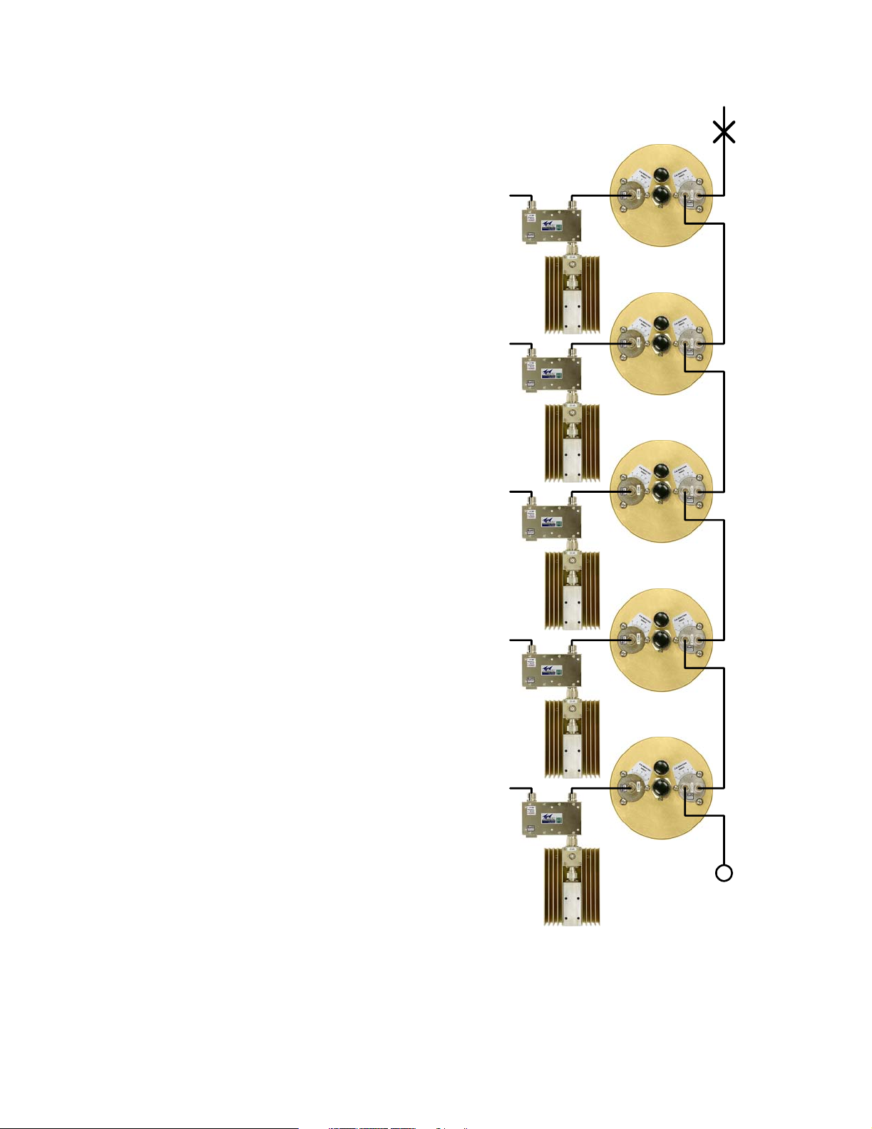
GENERAL DESCRIPTION
T
T
T
T
T
The model 73-67-11/25-XX-NN Series T-Pass
Transmit Combiners are designed to connect multiple transmitters to a common antenna. They use
three-port bandpass filters (called T-Pass cavities)
and ferrite isolators to provide low channel insertion loss, high isolation between transmitters, high
antenna-to-transmitter isolation, high intermodulation suppression, and excellent transmitter noise
suppression. T-Pass transmit combiners are
broadband and easily adaptable to the most difficult duplex system design requirements.
Transmitter Combiner (T-Pass)
X5
The block diagram of a typical transmit combiner is
shown in Figure 1. The T-Pass filter passes one
X4
narrow band of frequencies and attenuates all others with increasing attenuation above and below
the pass frequency. The T-Pass filter has a “dualport” output loop plate which allows the filter to be
easily connected to other T-Pass filters. Connections between the filters are made with a “thru-line”
cable that behaves like a low loss 50 Ohm transmission line. The thru-line cables are individually
optimized to their own channel frequency. No com-
X3
promises are necessary to accommodate other
channel frequencies. Each channel can therefore
be anywhere in a very broad frequency range.
An isolator is added at the input to each T-pass
channel to increase channel isolation. The ferrite
isolators will isolate the transmitter from unwanted
signals that enter the system via the antenna. The
X2
transmitter sees an excellent impedance match on
its output, because the isolator absorbs reflected
power that would otherwise enter the transmitters
output stage. This improves the stability, spectral
purity and long-term reliability of the transmitter.
The model 73-67-11/25-XX-NN Series T-Pass
transmit combiners are available with either 6.625”
or 10” cavities. TX combiners constructed with
X1
6.625” cavities are ideal for operation at channel
separations of 115 KHz or more, with 110 to 150
Watt transmitters. These models are suitable for
19” relay rack mounting or TX RX peg rack mounting. TX combiners constructed with high perfor-
S
mance 10” diameter cavities, which have higher
selectivity and power handling capabilities, allow
operation at 75 KHz minimum separation with 125
to 150 Watt transmitters. In addition, High power
10” diameter models are also available which contain 250 Watt dual isolators with 100 or 250 Watt
loads.
TX RX Systems Inc. Manual 7-9120-5 07/26/10 Page 1
Figure 1: Block diagram of a typical TX T-Pass
combiner. Typical five channel system shown as
an example.
Page 8
Frequency Range (MHz) 406 - 512 MHz
Cavity Type and Diameter 3/4 wave, 6.625” (168 mm)
Maximum Continuous Transmit Power 150 Watts
Isolator Load Power (Continuous) 73-67-11-2B-nn: 5W/25W [Note 3] ; 73-67-11-2D-nn: 5W/100W
Minimum TX-TX Separation at Cavity Loss 215 KHz @ -1.5 dB ; 115 KHz @ -2.5 dB
Typical TX-TX Isolation at Minimum Separation (dB) 80 dB
Typical Antenna - TX Isolation (dB) 70 dB
Typical TX Noise Suppression depends on cavity loss
Nominal Impedance (Ohms) 50
Maximum Input Return Loss (VSWR) -20 dB (1.22:1)
Temperature Range (°C) -30 to +60
Connectors, Input and Antenna N
Mounting Peg Rack ®
Mounting Options
Maximum Channels / Rack 15 [Note 4]
Dimensions 65.25” x 24” x 36” (H x W x D) [Note 6] ; (1659 x 610 x 914 mm)
Weight - Basic - Single Channel [lb (Kg)] 73-67-11-2B-nn: 36 (16.3) ; 73-67-11-2D-nn: 37 (16.7)
Weight - Expansion Channel Assembly [lb (Kg)] 73-67-11-2B-nn: 15 (6.8) ; 73-67-11-2D-nn: 16 (7.2)
Note 1: -nn in model number represents the number of channels.
Note 3: Models available with 5W/60W loads. same specifications as 25W and 100W models, except load power.
Note 4: -MC option reduces maximum number of channels to ten 10-inch or twelve 6.625-inch channels per rack.
Note 5: -LR systems are tuned and tested on customer frequencies, then disassembled for shipping.
Note 6: Rack depth with cavity tuning rods at maximum frequency. Rod travel is approximately 5.1” (130 mm).
Note 2: These specifications are applicable to 406 - 512 MHz models.
MC: 19” rackmount adapter plates, 17.5” high
LR: System supplied without Peg Rack ® [Notes 4,5]
Tab l e 1 : General specifications for 6.625” cavity system.
73-67-11-Series Systems
0
-5
-10
-15
-20
6.625" Diameter 3/4-Wave, Fo = 460 MHz
-25
-30
Attenuation (dB)
-35
IL = 1.0 dB
IL = 1.5 dB
IL = 2.0 dB
-40
IL = 2.5 dB
IL = 3.0 dB
-45
-50
0.01 0.1 1
10
Offset from Fo (MHz)
Figure 2: Typical transmitter noise suppression using 6.625” cavities.
TX RX Systems Inc. Manual 7-9120-5 07/26/10 Page 2
Page 9
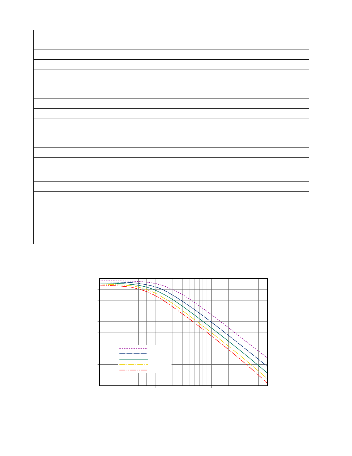
Frequency Range (MHz) 406 - 512 MHz
Cavity Type and Diameter 3/4-wave, 10” (254 mm)
Maximum Continuous Transmit Power 150 Watt
Isolator Load Power (Continuous) 5W/25W [Note 3]
Minimum TX-TX Separation at Cavity Loss 150 KHz @ -1.5 dB ; 75 KHz @ -2.5 dB
Typical TX-TX Isolation at Minimum Separation (dB) 80 dB
Typical Antenna - TX Isolation (dB) 70 dB
Typical TX Noise Suppression Depends on cavity loss
Nominal Impedance (Ohms) 50
Maximum Input Return Loss (VSWR) -20 dB (1.22 : 1)
Temperature Range (°C) -30 to +60
Connectors, Input and Antenna N
Mounting Peg Rack ®
Mounting Options
Maximum Channels / Rack 12 [Note 4]
Dimensions 79.5” x 24” x 36” (H x W x D) [Note 6] ; (2019 x 610 x 914 mm)
Weight - Basic Single-Channel [lb (Kg)] 14 (18.6)
MC: 19” rackmount adapter plates, 17.5 “ high
LR: System supplied without Peg Rack ® [Notes 4,5]
Weight - Expansion Channel Assembly [lb (Kg)] 19 (8.6)
Note 1: -nn in model number represents the number of channels.
Note 3: Models available with 5W/60W loads. same specifications as 25W and 100W models, except load power.
Note 4: -MC option reduces maximum number of channels to ten 10-inch or twelve 6.625-inch channels per rack.
Note 5: -LR systems are tuned and tested on customer frequencies, then disassembled for shipping.
Note 6: Rack depth with cavity tuning rods at maximum frequency. Rod travel is approximately 5.1” (130 mm).
Note 2: These specifications are applicable to 406 - 512 MHz models.
Table 2 : General specifications for 10” cavity systems.
73-67-25-Series Systems
0
-5
-10
-15
-20
-25
-30
Attenuation (dB)
-35
-40
-45
10" Diameter 3/4-Wave, Fo = 460 MHz
IL = 1.0 dB
IL = 1.5 dB
IL = 2.0 dB
IL = 2.5 dB
IL = 3.0 dB
-50
0.01 0.1 1
10
Offset from Fo (MHz)
Figure 3: Typical transmitter noise suppression using 10” cavities.
TX RX Systems Inc. Manual 7-9120-5 07/26/10 Page 3
Page 10
The TX combiners can be expanded one channel
at a time with factory-tuned, easy-to-install expansion channel assemblies. Expansion is usually
accomplished without modifications to the existing
system, and usually amounts to nothing more than
placing a new channel assembly, or several, on top
of the existing system. New channel frequencies
can be above, below, or between existing channel
frequencies.
The number of channels in the combiner is indicated by the last two digits of the model number in
place of the NN designation. All of the information
for both installation and expansion is included in
this manual. The combiner is easy to install and
has been factory tuned in most cases so that no
adjustments are necessary. The specifications for
the 73-67-11/25-XX-NN family of T-Pass combiners are listed in Tables 1 and 2 for the 6.625” and
10” cavities respectively. The curves shown in Fig-
ures 2 and 3 show the typical transmit noise suppression for the 6.625” and 10” cavity systems
respectively. Noise suppression depends on the
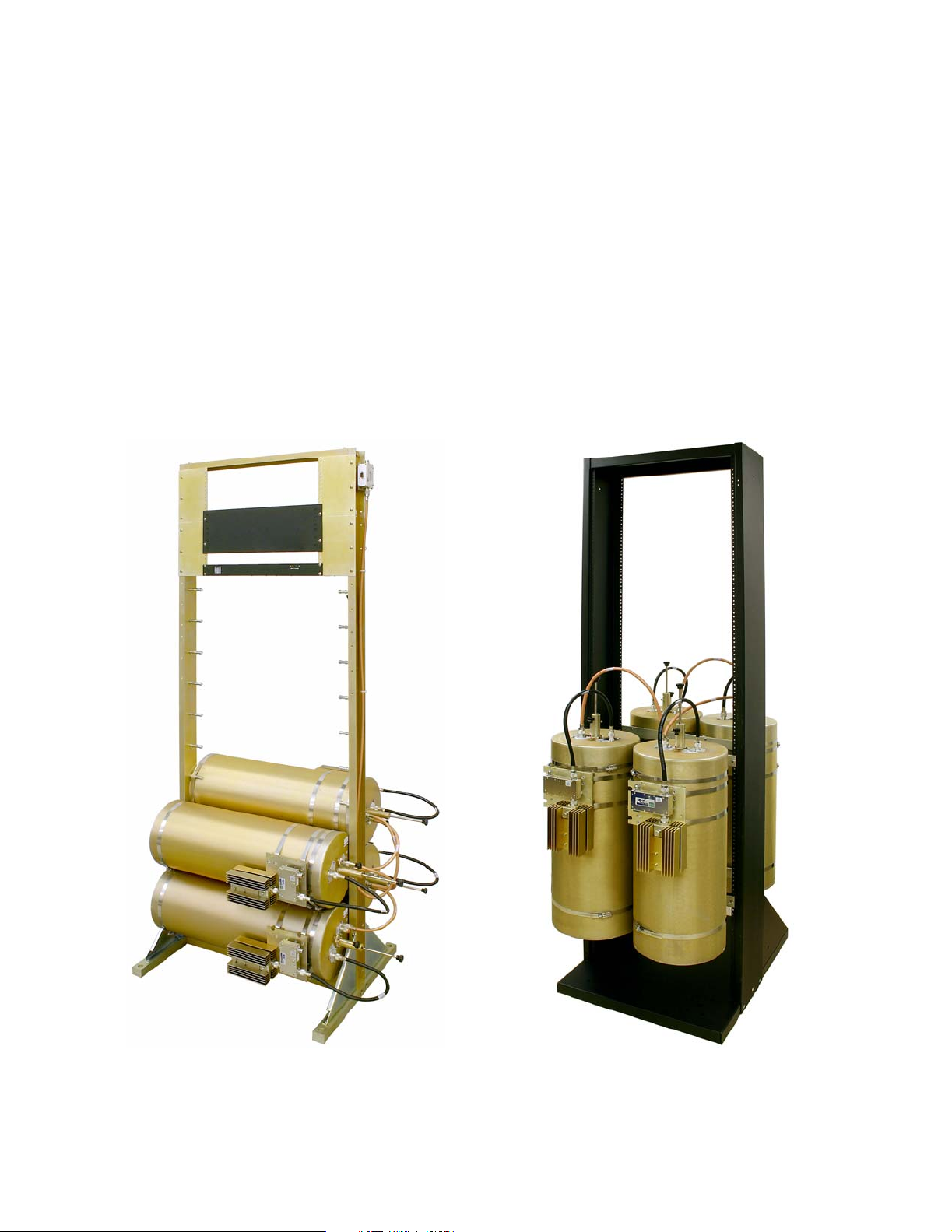
cavity’s loss setting. Figure 4 shows a typical Peg
rack model and Figure 5 shows a typical 19” rack
mount model.
UNPACKING
It is important to visually inspect the system components for any shipping damages as soon as possible after taking delivery. It is the customers
responsibility to file any necessary damage claims
with the carrier.
Figure 4: Example of typical Peg-rack model
using 10” cavities.
TX RX Systems Inc. Manual 7-9120-5 07/26/10 Page 4
Figure 5: Example of typical Relay-rack model
using 10” cavities.
Page 11

The transmit combiner is a very rugged device and
is well packed for damage-free shipping to any
place in the world. However, a high impact during
shipping can have a detrimental affect. A damaged
shipping container is a sure sign of rough handling.
The most easily damaged parts of the combiner
are the tuning rods. These rods are marked where
they exit from the locking nut with a dab of red varnish or other color/type of paint. If this seal appears
to be broken it may indicate that the system has
been detuned in transit.
INSTALLATION OVERVIEW
The combiner should be located in a dry and level
area, indoors. It is best if all transmitters are as
equal in distance as possible from the combiner so
that cable losses are the same for all channels.
Figure 6 shows a suggested orientation for the
equipment. Two points are important. First, a work
area space should be left as illustrated so that the
tuning controls are easy to access. This will facilitate tuning when channel frequencies are
changed. Secondly, space is needed when adding
expansion channels. If there is a lack of space to
access the side of the combiner, then plan to allow
the rack to be moved into the indicated work area
to facilitate adding channels. This will require some
slack in the cables that connect to the station transmitters. Each transmitter connects to its respective
channel through an ‘N style’ female connector on
the isolator. We recommend using a high quality
double shielded or semi flexible cable.
This system is designed for use with separate
transmit and receive antennas. For best operation,
the transmit and receive antennas should be separated vertically by 20 feet with little or no horizontal
offset between antennas. Lesser separations can
be used but with an increased risk of harmful interference between radio systems. In most cases, it
will be desirable to mount the receive antenna
higher than the transmit antenna to maximize the
talk-back range of low power portable radios.
RF Cables and Connectors
All connections to and from the combiner system
should be made with double-shielded or semi-rigid
heliax cable. High quality 'N' connectors that use
either silver or gold plated contacts should be
used.
Intermodulation Considerations
Following the previously mentioned antenna spacing recommendations will go a long way toward
minimizing or eliminating intermodulation (IM)
interference. IM is the result of a frequency mixing
process that occurs when two or more RF signals
are present simultaneously in the same circuitry
where nonlinearities occur. Product frequencies
generated have frequencies that are determined by
relatively simple mathematical relationships such
as F(im) = 2F1-F2 and are normally determined by
doing a computer intermodulation analysis for the
antenna site. These products can be generated in
a corroded tower joint, metal-roofing, transmitter
final amplifier or the receiver front-end.
T-Pass
Transmitter
Combiner
Radio
Cabinet
TX RX Systems Inc. Manual 7-9120-5 07/26/10 Page 5
Radio
Cabinet
Work
Area
Figure 6: Typical combiner installation.
Radio
Cabinet
Radio
Cabinet
Page 12

Both cavity filters and ferrite isolators isolate the
transmitters connected to the combiner from oneanother thus reducing intermodulation interference.
However in all transmitter combiners, intermodulation products are reduced in strength but never
completely eliminated. They have to be reduced by
an amount to meet the federal Communications
Commission,
43 + 10 Log(Power Out)
rule for spurious output reduction. Because of the limitations
imposed by the tension and friction joints in connectors, IM products will be down 100 to 120 dB
below carrier so they are still strong enough to
cause problems if they fall on a near-by receiver
frequency.
Transmitter
To avoid transmitter generated IM problems, do
not put two channels on the same combiner that
your IM software predicts will cause interference by
generating either 3rd or 5th order IM products.
Having at least two transmitter combiners allows
maximum flexibility in dealing with transmitter generated IM.
General Installation Procedure
1) Install the peg rack or relay rack in the radio
equipment room.
2) Connect the transmitters and the transmitting
antenna to the appropriate connectors on the
cavities.
Wattmeter 2
T-Pass
Cavity Filter
50 Ohm
Load
Transmitter
Wattmeter 1
UG57
Male-Male
Transmitter
Single
or Dual
Section
Isolators
Single
or Dual
Section
Isolators
Single
or Dual
Section
Isolators
Channel 3
Channel 2
Channel 1
UG27 Elbow Connector
& UG57 Male-Male
Adaptor
This T-Pass Loop
requires a 3-1268
short circuit
connector
Figure 7: Equipment hookup for measuring T-Pass channel performance.
TX RX Systems Inc. Manual 7-9120-5 07/26/10 Page 6
Page 13

3) Verify proper operation of each channel by
measuring the power output for each individual
channel.
TRANSMITTER COMBINER CHECKOUT
It is recommended that the performance of the
transmitter combiner be checked initially and data
recorded for future reference. This is done by measuring the input and output power of each channel
and recording the data. Figure 7 shows the equipment hook up.
Required Equipment
If a power monitoring system is not installed along
with the combiner, two Bird Model 43 thruline wattmeters or equivalent can be used. They should be
equipped with elements for the frequency band of
interest and rated for the expected transmitter
power output. The use of two wattmeters eliminates errors that can occur from changing cable
lengths. The measurements should only be done
one channel at a time because most wattmeters
cannot accurately measure the total power of two
or more transmitters simultaneously. A pocket calculator with Log functions makes for easy calculation of power loss in dB using this measured data.
PROCEDURE
Start with channel 1 and proceed to the next higher
channels. The two wattmeters should be connected to the equipment as shown in figure 7. Note
that the use of the elbow and/or male-male connectors allows the shortest connections and negligible hook up loss. Longer cable lengths will tend
to increase measurement error.
It is important that the same wattmeters and wattmeter elements be used in the same position
throughout the tests. The serial numbers of the
wattmeters should be recorded for future reference. Wattmeter elements may not have serial
numbers so they need to be labeled or otherwise
keyed to a specific wattmeter to assure repeatability of the measurements.
MEASUREMENT ACCURACY
The Bird thruline wattmeter has a measurement
accuracy of +/- 5% of full scale. When using a 100
watt element in this meter, the measurement error
can be as great as + or - 5 watts.
As an example of the actual dB loss readings that
might be produced using the wattmeter method,
consider a T-Pass channel that has a factory mea-
sured loss of 3.0 dB. We would expect that a 100
watt transmitter would produce 50 watts out of this
channel but the actual wattmeter reading for the
input power could measure as low as 95 watts to
as high as 105 watts. The measured output power
could run from 45 to 55 watts. It is possible that the
output reading may be 5 watts low while the input
reading is 5 watts high or just the opposite. These
two extremes would yield the following dB loss values:
For a Power Out (PO) of 45 watts and a Power
Input (PI) of 105 watts:
Loss (dB) = 10 Log10 (45/105)
Loss (dB) = -3.7
For a PO of 55 watts and PI of 95 watts:
Loss (dB) = 10 Log10 (55/95)
Loss (dB) = -2.4
So the calculated loss for this channel can run from
-2.4 to -3.7dB and be acceptable considering the
measurement error factor. The actual error could
be much greater if a 250 watt element was
used; the measured values could vary by as much
as +/- 12.5 watts so using a wattmeter element with
the smallest possible rating is important for accuracy. Use of between series adapters or UHF type
connectors for making connections to the wattmeters, device under test or loads could make this
error even worse due to the additional impedance
mismatch that these connectors can cause.
GENERAL TUNING INFORMATION
T-Pass transmitter combiners are pre-tuned at the
factory and usually require no adjustment. T-Pass
expansion channels are also pretuned but may
require fine tuning after being installed in an existing system. Channels that are close in frequency
(adjacent channels in the multicoupler) to the
expansion channel may also benefit from fine tuning due to the slight interaction that occurs with the
new channel. The procedures that follow may be
used at any time to verify that any or all channels
are properly tuned or to correct any misalignments.
It is interesting to note that T-Pass filters, bandpass
filters and cavity filters in general can act as impedance transformers as well as filters. It is for this
reason that many field service personnel claim that
they can always tune a filter or duplexer better than
the factory. What isn't generally realized is that
their tuning efforts are usually producing better
impedance matching between transmitter and
antenna which can be improved by the transform-
TX RX Systems Inc. Manual 7-9120-5 07/26/10 Page 7
Page 14

ing action of filters. Since the filters are usually
r
s
r
s
tuned using laboratory grade 50 ohm loads, the
tuning adjustment that produces this improved
match will be slightly different than the factory
adjustment. While this tuning may produce slightly
greater power output readings, it will rarely produce any discernible change in system performance and may detune any notching circuitry
contained in the cavities.
It is our recommendation that channel tuning only
be attempted under the previously mentioned conditions or when it is suspected that the combiner
has been tampered with or subjected to extreme
shock in shipping or installation. This condition is
indicated when the channel loss is in excess of that
expected from actual measurement of power input
and output.
Tuning Specifics
Tuning of the combiner consists of tuning the individual T-Pass channels. T-Pass channel tuning
involves cavity filter tuning. The isolators are
broad band and do not require adjustments.
The procedures for tuning cavities follows.
FINE CAVITY TUNING
Figure 8 shows hookups which are suitable for fine
tuning any channel under power while installed in
the combiner. The term fine tuning here refers to
cavities that have already been tuned to frequency
and may only require adjustment of the fine tuning
control (+/- 50 KHz). The transmitter is used as a
signal source and the cavity is adjusted for minimum reflected power.
Procedure
With the transmitter keyed, the cavity fine tuning
control is adjusted (pushed in or out) to obtain a
minimum meter reading. See Figure 9 for a detail
of the cavity tuning controls. If a minimum meter
reading is obtained with the fine tuning rod fully in
or completely out, do the following:
1) Set the fine tuning rod so that about 1/2 of its
length is inserted into the cavity.
2) Loosen the coarse tuning rod locking screw (5/
32”/4mm Allen/Hex-key wrench required) and
move the rod in or out slightly to obtain minimum meter reading. Small movements of the
coarse tuning rod are facilitated by tapping the
rod with the handle end of a screw driver while
gently pushing or pulling the main tuning rod.
Tighten the coarse tuning locking screw.
3) Adjust the fine tuning control for a minimum
meter reading.
Fine
Tuning
Two Single Section
or One Dual Isolators
Transmitter
Input
50 Ohm
Termination
Figure 8: Using a wattmeter for T-Pass cavity fine tuning.
Output
Coarse
Tuning
Wattmeter
Output
Section
Termination
T-Pass
Cavity Filter
To Othe
Channel
To Othe
Channel
TX RX Systems Inc. Manual 7-9120-5 07/26/10 Page 8
Page 15

Coarse Tuning Rod
Fine Tuning Rod
Coarse Tuning Lock
10-32 Cap Screw
Cavity Resonator
Input/Output Port
Loop Plate
Hold Down Screws
Loop Plate Assembly
Calibration Index
Figure 9: T-Pass cavity tuning controls details.
4) Tighten the fine tuning locking mechanism.
CAVITY TUNING TIP
When tuning a cavity that has been in service for
some time it is not unusual to find the main tuning
rod hard to move in or out. This occurs because TX
RX uses techniques borrowed from microwave
technology to provide large area contact surfaces
on our tuning plungers. These silver plated surfaces actually form a pressure weld that maintains
excellent conductivity. This pressure weld develops over time and must be broken to move the
main tuning rod. This is easily accomplished by
gently tapping the tuning rod with a plastic screwdriver handle or small hammer so that it moves into
the cavity. The weld will be broken with no damage
to the cavity.
When adjusting the coarse tuning rod, it is easy to
put the cavity far off resonance and cause most of
the transmitter power to be reflected back into the
isolator output section load. This load should be
capable of dissipating this power or damage could
result. If in doubt about the loads capability, follow
the coarse tuning procedure outlined below. It is
based on the use of a tracking generator which
avoids the need to consider power levels.
Input/Output Port
Loop Plate Assembly
Calibration Mark
Calibration Index
Fine Tuning Lock
Knurled Thumb Nut
COARSE CAVITY TUNING
When a T-Pass cavity frequency has to be
changed by over 100 KHz, adjustment of the main
tuning rod is required. Large frequency changes
are more easily observed when using a tracking
generator and a return loss bridge to give a swept
display of the return loss curve. The return loss
curve is a very precise indicator of T-Pass cavity
tuning. The test equipment hookup for doing this is
illustrated in Figure 10 and uses the following
equipment or its equivalent;
1) Spectrum Analyzer that covers the frequencies
of interest such as the Bird Technologies “Signal Hawk ™”.
2) Signal generator capable of producing the frequencies of interest.
3) Eagle Return Loss Bridge (35 dB directivity).
Model RLB150N3A.
4) Double shielded coaxial cable test leads
(RG142 B\U or RG223/U).
5) 50 Ohm load with at least -35 dB return loss
(1.10:1 VSWR).
6) 3-1268 short circuit connector.
TX RX Systems Inc. Manual 7-9120-5 07/26/10 Page 9
Page 16

Spectrum Analyzer
Bird SignalHawk
Signal Generator
RLB - 150 Bridge
LOAD
PROCEDURE
1) Set the spectrum analyzer for the desired center frequency (display center) and vertical scale
of 10 dB/div. Set the signal generator for the
desired center frequency.
2) Connect the return loss bridge to the spectrum
analyzer and signal generator as shown in figure 10 but do not connect it to the cavity. Leave
the test port (called the load port) on the bridge
open.
3) Set up a 0 dB return loss reference display on
the spectrum analyzer. Then connect the return
loss bridge.
4) Loosen the fine tuning rod locking nut and set
the fine tuning rod so that 1/2 its length is
inserted into the cavity.
5) Loosen the main tuning rod locking screw and
move the main tuning rod in or out to obtain
maximum return loss at the desired frequency.
Small movements of the main tuning rod are
facilitated by tapping the rod with the handle
end of a screw driver while gently pushing or
pulling the main tuning rod.
6) Lock the Main and Fine tuning rods and reconnect the cavity into the system. Use the previously outlined fine tuning procedure to verify
proper tuning under power.
Retuning System To All New Frequencies
50 Ohm Load
T-Pass
Cavity Filter
When retuning the combiner to all new frequencies
perform the following procedure in a step-by-step
fashion;
1) Determine new thruline cable lengths for the
new channels and the specific stacking order in
the rack. TX RX Systems Sales engineers will
assist by making the calculations using their
design software. Due to variations in coaxial
cable characteristics and assembly techniques,
factory supplied cables are recommended.
2) Use the coarse tuning procedure to tune each
3-1268
Short Circuit
Connector
cavity channel to the new transmitter frequencies.
3) Connect the channels according to the new
thru-line cable chart.
Figure 10: Coarse tuning a T-Pass cavity.
TX RX Systems Inc. Manual 7-9120-5 07/26/10 Page 10
Page 17

4) Fine tune each channel using the fine tuning
procedure starting with channel 1 and proceeding to the next higher channel. After tuning all
channels, repeat this step a second time to verify that their is no more channel interaction.
(1) Cavity and isolator mounting hardware.
(1) T-Pass thru-line cable.
(1) T-Pass thruline chart.
5) Verify channel losses if desired using the
checkout procedure outlined previously.
Combiner Expansion
Expansion channels for your combiner may be
ordered directly from TX RX Systems or its authorized representative. If you wish, a TX RX Systems
engineer will help you select the right model and
any required options.
The expansion channel and options are shipped
with mounting instructions and a new T-Pass
Thruline cable sheet which shows the exact mounting location of the new channel in the existing system. In most cases, this channel will be added
directly to the next topmost position in the rack and
the antenna connection will then move to this cavity. A new thruline cable will connect this channel to
the existing cavities.
The system engineer may also advise that the cavity insertion loss on some of the existing channels
needs to be changed in order to accommodate a
new channel. This can be necessary when the new
channel is much closer in frequency separation to
existing channels than was previously encountered. This usually means increasing the cavity
loss for all close spaced channels which provides
the increased selectivity required. Cavity insertion
loss values are shown on the T-Pass Thruline
cable sheet.
Typical Expansion Channel installation
The following text is a procedure for adding expansion channel components to a typical T-Pass
Transmit Combiner system. Please keep in mind
that if instructions are shipped with the expansion
components they would supersede these procedures.
Typical Parts Included: (Quantity and Description)
(1) T-Pass Cavity Assembly.
(1) Dual or single isolator with load(s).
PEG RACK PROCEDURE
(6.625” AND 10” CAVITIES)
1) Determine the location of the Expansion Channel in the rack by consulting the new
THRULINE cable chart.
2) Mount the cavity in the peg rack using two (2)
stainless band clamps, refer to Figure 11.
3) Rotate the cavity body so that the connectors
are oriented the same as those on the other
cavities and that no cavity-end cap screws are
preventing a flush fit with a mounting peg.
4) Tighten the cavity mounting clamps.
5) Attach the isolator mounting plate to the cavity
using two (2) band clamps. Clamp screws
should be positioned as shown in figure 11. Do
not tighten the clamps.
6) Rotate the isolator mounting bracket so that the
isolator is in the vertical plane as illustrated,
forming a smooth line in relation to the other
channels in the rack.
7) Due to the limited space, tightening may require
the use of a 5/16" open end wrench. Tighten
both clamps securely.
8) Connect the black isolator-to-cavity cable using
a pair of cable pliers to tighten-up the connectors.
9) Connect the new channel to the combiner using
the proper length T-Pass Thruline cable. Use a
pair of cable pliers to tighten these connections.
The required length thruline cable and
NOTE
new cabling chart has either been factory supplied or is to be determined
and fabricated by the customer as
determined at the time of order. Use
T-Pass thruline design sheets supplied by the factory.
(1) Isolator to cavity interconnect cable.
10) If necessary, reset the cavity insertion loss of
adjacent channels as noted on the Thru-line
TX RX Systems Inc. Manual 7-9120-5 07/26/10 Page 11
Page 18

Figure 11: Peg-rack mounting details.
cable sheet. Follow the procedure outlined
below under Setting Cavity Insertion Loss.
11) Fine tune the T-Pass cavity of the expansion
channel according to the fine tuning procedure
outlined earlier.
RELAY RACK PROCEDURE
(10” CAVITIES)
Because of their width, 10” cavities
NOTE
are mounted in relay racks with a vertical orientation as shown in Figure
12.
1) Install the expansion cavities to the rack above
existing channels using four mounting screws.
Make sure you leave sufficient space between
the upper and lower cavity groups so that the
tuning rods and interconnect cables do not
interfere.
2) Connect the black isolator-to-cavity cable using
a pair of cable pliers to tighten-up the connectors.
3) Connect the new channel to the combiner
using the proper length T-Pass Thruline cable.
Use a pair of cable pliers to tighten these connections.
The required length thruline cable and
NOTE
new cabling chart has either been factory supplied or is to be determined
and fabricated by the customer as
determined at the time of order. Use
T-Pass thruline design sheets supplied by the factory.
4) If necessary, reset the cavity insertion loss of
adjacent channels as noted on the Thru-line
cable sheet. Follow the procedure outlined
below under Setting Cavity Insertion Loss
.
TX RX Systems Inc. Manual 7-9120-5 07/26/10 Page 12
Page 19

Screw
Screw
Screw
Screw
Figure 12: Relay rack mounting details. Ten-inch cavities shown as an example.
5) Fine tune the T-Pass cavity of the expansion
channel according to the fine tuning procedure
outlined earlier.
RELAY RACK PROCEDURE
(6.625” CAVITIES)
Because of their width, 6.625” cavities
NOTE
are mounted on relay racks in a hori-
1) Determine the location of the expansion channel in the rack by consulting the new
THRULINE cable chart.
2) If necessary install an empty cavity deck in the
rack using 4 Phillips screws. If there is room on
an already existing cavity deck then skip this
step of the procedure.
zontal orientation on cavity deck
plates.
3) Mount the cavity on the deck by laying the cavity onto the “V shaped” cavity bracket.
TX RX Systems Inc. Manual 7-9120-5 07/26/10 Page 13
Page 20

4) Rotate the cavity body so that the connectors
are oriented the same as those on the other
cavities in the system. Secure the new cavity to
the brackets using (2) stainless band clamps.
5) Tighten the cavity mounting band clamps.
6) Connect the black isolator-to-cavity cable using
a pair of cable pliers to tighten-up the connectors.
7) Connect the new channel to the combiner
using the proper length T-Pass Thruline cable.
Use a pair of cable pliers to tighten these connections.
The required length thruline cable and
NOTE
new cabling chart has either been factory supplied or is to be determined
and fabricated by the customer as
determined at the time of order. Use
T-Pass thruline design sheets supplied by the factory.
8) If necessary, reset the cavity insertion loss of
adjacent channels as noted on the Thru-line
cable sheet. Follow the procedure outlined
below under Setting Cavity Insertion Loss
.
9) Fine tune the T-Pass cavity of the expansion
channel according to the fine tuning procedure
outlined earlier.
Setting Cavity Insertion Loss
It is sometimes necessary to reset the insertion
loss of a T-Pass cavity filter in order to change its
selectivity. Increasing the loss will increase the
cavity selectivity which may be necessary to
accommodate more closely spaced channels.
observed across the tee. The depth of the rejection
notch is directly related to the loop's coefficient of
coupling.
The first procedure uses precision rotary attenuators, a signal generator and a RF millivolt meter to
provide very accurate results. The actual loss setting obtained when this procedure is carefully followed will be within one tenth of a dB of the desired
value and the return loss will be 20 dB (1.25:1) or
better.
The second procedure uses a spectrum analyzer
and a signal generator and produces slightly less
accurate results. When this procedure is carefully
followed, the loss settings will be within two tenths
of a dB of the desired value and the return loss will
usually be -15 dB (1.5:1 VSWR) or better. The
advantage of this procedure is that it is much faster
to do, does not require precision attenuators and
will yield acceptable results in most cases.
Table 3 is a reference chart for setting T-Pass cavity loss with either procedure. The chart shows the
desired cavity loss settings and the reference setting for both the T-Pass and bandpass loop assembly. The reference notch depth for a given loss is
that which can be observed across a tee connector
connected to either loop assembly.
Calibration
Mark
Loop Locking
Screws (6 places)
Changing the loss is accomplished by rotating the
coupling loops to change the coefficient of coupling. Both loops are normally adjusted for a given
insertion loss setting. Most T-Pass cavities have a
calibration index label beside both loops that gives
a relative indication of their settings, see Figure
13. In actual practice, these marks are not accurate
enough for setting different loss values consistently.
Two procedures are offered for setting the cavity
Bandpass
Loop
T-Pass
Loop
loss. Both procedures take advantage of the fact
that when a tee connector is placed on a single
Figure 13: Top view of T-Pass cavity.
bandpass or T-Pass loop, a rejection notch can be
TX RX Systems Inc. Manual 7-9120-5 07/26/10 Page 14
Page 21

Cavity Loss (dB) Coupling Loop Type TXRX Part # Reference Notch Depth
1.0
1.5
2.0
2.5
3.0
T-Pass 3-3724 -9.2
Bandpass 2-0675 -12
T-Pass 3-3724 -7.4
Bandpass 2-0675 -10.2
T-Pass 3-3724 -5.6
Bandpass 2-0675 -8.8
T-Pass 3-3724 -4.4
Bandpass 2-0675 -8.0
T-Pass 3-3724 -3.6
Bandpass 2-0675 -7.2
Table 3: Cavity insertion loss reference loop settings.
Cavity Loss Setting Procedure 1
This procedure uses precision rotary attenuators, a
signal generator and an RF millivolt meter.
REQUIRED TEST EQUIPMENT
1) Signal generator capable of producing a CW
signal level of at least -10 dBm with variable
output level capability at the frequency of interest.
2) An RF voltmeter with a 0.001 V (-50 dBm)
scale and a 50 ohm input adapter. Helper
Instruments RF millivolter used for this example.
3) Rotary Attenuators, 1@ 0-1 dB in 0.1 dB increments. 1@ 0-10 dB in 1.0 dB increments. 1@
0-70 dB in 10 dB increments. JFW Industries
model 50BR-017.
4) Two 10 dB fixed attenuator pads with BNC
connectors. JFW Industries model 50F-010.
5) UG-914/U, BNC(F) to BNC(F) union.
TX RX Systems' part # 8-5805.
6) UG-28A/U, N(F), N(F), N(F) tee.
7) UG-57B/U, N(M)-N(M) coupling.
8) Two, UG-201A/U BNC(F)-N(M) adapter.
TX RX Systems' part # 8-5814.
9) 50 ohm coaxial cable test leads with BNC male
connectors (high quality cable).
A spectrum analyzer may be used in place of the
RF voltmeter. However, the personnel doing the
work should fully understand the procedure and
understand the use of the analyzer for this application.
We have found it convenient to use test cables with
BNC connectors. They allow for more convenient
connection to test equipment and to small attenua-
TX RX Systems Inc. Manual 7-9120-5 07/26/10 Page 15
Page 22

Modulated
Signal Source RF Voltmeter
2
0 0 000 0 00
All cables are 50 Ohm
ZERO
SET
coaxial. Double shielded
cables preferred.
1
4567
3
50 Ohm Adaptor
3
8
9
10
ZERO
SET
UG914/U
0.1 dB/Div. 1.0 dB/Div. 10 dB/Div.
Female-Female
Connector
10 dB Attenuator Pads
Figure 14: Setting loop adjustment reference level.
tor pads. UG-201 BNC to N adapters are used
when connections to N connectors are needed.
PROCEDURE FOR T-PASS LOOP
1) Set the signal generator at the desired frequency (within 1 MHz of operating frequency)
and an output level of approximately -10 dBm.
Set the rotary attenuators for the Reference
Notch Depth Value shown in table 3 for the
desired insertion loss.
2) Connect the test leads together through the
female union, as shown in Figure 14, and
adjust the range switch and the zero set on the
voltmeter for a convenient reference level (
level of 2 on the 0 to 3 scale for example
) on the
meter. The generator output level may also be
adjusted slightly if necessary.
3) Remove the bandpass loop from the cavity and
reinsert it, connector end first, back into the cavity and tighten all 3 screws securely. See Fig-
ure 15.
4) Set all three attenuators for 0 dB but leave them
in the circuit.
5) Connect a UG-28A/U Tee connector and UG57B/U coupling to the T-Pass loop as shown in
figure 15. Then connect the test leads as
Rotary Attenuators
Set to Loop Reference Settings
shown. Make sure to install the 3-1268 short circuit connector from the top of the T-Pass rack.
6) Loosen the main tuning rod locking screw and
slowly slide the tuning rod in or out to obtain a
dip (minimum voltage) in the meter reading
which indicates cavity resonance. Use the fine
tuning control to maximize the dip (the fine tuning rod should not be full in or out which would
indicate that slight adjustment of the main tuning rod is necessary). Note the meter reading.
7) If the meter reading is greater or less than the
reference level from step 2, the T-Pass loop
A
rotation will have to be adjusted. If the meter
reading is greater than the reference level, the
loop will have to be rotated so that the calibration mark on the loop points to a slightly higher
number on the calibration index label. Conversely, if the meter reading is less than the reference, the loop will have to be rotated so that
the index mark points to a slightly lower number
on the calibration index. Loosen the three loop
locking screws and rotate the loop so that the
index mark is moved to the next higher or lower
calibration tag number as needed and tighten
the 3 locking screws. Note that tight screws are
necessary for accuracy.
TX RX Systems Inc. Manual 7-9120-5 07/26/10 Page 16
Page 23

Modulated
Signal Source RF Voltmeter
Short Circuit Connector
3-1268 from top of rack
10 dB Pad 10 dB Pad
Figure 15: Setting the T-Pass loop using step attenuators.
UG-28A/U
UG-57B/U
T-Pass
Loop
50 Ohm Adaptor
0.1 dB/Div. 1.0 dB/Div. 10 dB/Div.
Rotary Attenuators
Set to Loop Reference Settings
Bandpass Loop turned upside down
with connector inserted into cavity.
Loop visible and screws tight.
8) Repeat steps 6 and 7 until the minimum meter
reading is equal to the reference level from step
2. Rotation of loops will change the cavity frequency slightly.
9) The Bandpass loop should be reinstalled with
the connector facing upward and the ground
point circle oriented toward the center of the
cavity as shown in Figure 16.
10) Remove the short circuit connector from the T-
Pass loop.
PROCEDURE FOR BANDPASS LOOP
1) Maintain the previous signal generator settings
and set the rotary attenuators for the proper setting as shown in table 3 for the Bandpass Loop.
2) Connect the test leads together through the
female union and adjust the range switch and
the zero set on the voltmeter for a reference
level (
A level of 2 on the 0 to 3 scale is conve-
nient
) on the meter. See figure 14. The generator output level may also be adjusted slightly if
convenient.
3) Set all three attenuators for 0 dB but leave them
in the circuit.
4) Connect a UG-107 Tee and the UG-57B/U to
the Bandpass loop as shown on figure 16. Then
connect the test leads as shown. Make sure the
short circuit connector has been removed from
the T-Pass loop.
5) Loosen the main tuning rod locking screw and
slowly slide tuning rod in or out to obtain a dip
(minimum voltage) in the meter reading which
indicates cavity resonance. Use the fine tuning
control to maximize the dip (the fine tuning rod
should not be full in or out which would indicate
that slight adjustment of the main tuning is necessary). Note the meter reading.
6) If the meter reading is greater or less than the
reference level from step 2, the bandpass loop
rotation will have to be adjusted. If the meter
reading is greater than the reference level, the
loop will have to be rotated so that the calibration mark on the loop, points to a slightly higher
number on the calibration index label. Conversely, if the meter reading is less than the ref
erence, the loop will have to be rotated so that
TX RX Systems Inc. Manual 7-9120-5 07/26/10 Page 17
Page 24

Modulated
Signal Source RF Voltmeter
UG-28A/U
UG-57B/U
Bandpass
Loop
50 Ohm Adaptor
10 dB Pad 10 dB Pad
Figure 16: Setting the bandpass loop using step attenuators.
the index mark points to a slightly lower number
on the calibration index. Loosen the three loop
locking screws and rotate the loop so that the
index mark is moved to the next higher or lower
calibration tag number as needed and tighten
the 3 locking screws. Note that tight screws are
necessary for accuracy.
7) Repeat steps 5 and 6 until the minimum meter
reading is equal to the reference level from step
2. Rotation of loops will change the cavity frequency slightly.
0.1 dB/Div. 1.0 dB/Div. 10 dB/Div.
Rotary Attenuators
Set to Loop Reference Settings
Small Circle on Bandpass Loop indicates
ground end of loop and should be
oriented as shown.
Previously calibrated T-Pass Loop 3-1268
short circuit removed.
3) UG-914/U, BNC(F) to BNC(F) union.
TX RX Systems' part # 8-5805.
4) UG-28A/U, N(F), N(F), N(F) tee.
5) UG-57B/U, N(M)-N(M) coupling.
6) Two, UG-201A/U BNC(F)-N(M) adapter.
TX RX Systems' part # 8-5814.
7) 50 ohm coaxial cable test leads with BNC male
connectors (high quality cable).
8) Make sure that all the loop locking screws are
tight. The cavity loops are now set and the cavity should now be tuned to the desired frequency.
We have found it convenient to use test cables with
BNC connectors. They allow for a more convenient
connection to test equipment and small attenuator
pads. UG-201 BNC to N adapters are used when
connections to N connectors are needed.
Cavity Loss Setting Procedure 2
This procedure uses a spectrum analyzer and signal generator.
PROCEDURE FOR T-PASS LOOP
1) Remove the screws that hold in the bandpass
loop assembly; remove the assembly; invert it
REQUIRED TEST EQUIPMENT
1) Spectrum Analyzer and a signal generator.
and place it back into the cavity (see Figure
17). The coupling loop will be visible. Install and
tighten the three locking screws.
2) Two 10 dB fixed attenuator pads with BNC
connectors. JFW Industries model 50F-010.
TX RX Systems Inc. Manual 7-9120-5 07/26/10 Page 18
Page 25

UG-28A/U
n
UG-57B/U
T-Pass
Loop
Connector 3-1268
Spectrum Analyzer
Bird SignalHawk
Signal Generator
10 dB Pad10 dB Pad
Short Circuit
from top of rack
Bandpass Loop
turned upside dow
with connector
inserted into cavity.
Loop visible and
screws tight.
Figure 17: Setting a T-Pass loop for specific cavity insertion loss.
2) Connect the test leads to the spectrum analyzer; turn it on and let it warm up for at least 30
minutes.
3) Connect the 10 dB attenuator pads to the test
leads. They will remain connected for all subsequent measurements.
4) Note the Reference Notch Depth value for the
T-Pass loop assembly to be adjusted from table
3.
5) Set the spectrum analyzer for the frequency of
the channel of interest (within 1 MHz of actual
operating frequency).
6) If the Reference Notch Depth is 8 dB or less
then set the display for a vertical range of 2dB/
div otherwise set it for 10dB/div.
7) Temporarily connect the test leads from the
spectrum analyzer together through a UG-914
BNC union to set the zero reference.
8) Connect a UG-28 tee and a UG-57 coupling to
the T-Pass loop as shown in figure 17.
9) Connect the test leads from the spectrum analyzer to the tee connector as shown in figure 17.
10) Adjust the cavities main tuning rod so that a
rejection notch appears in the center of the display.
11) Loosen the three loop locking screws and
rotate the loop to obtain the reference notch
depth from step 4. Tighten the T-Pass loop
locking screws only. Note that the tightness of
the locking screws affects the depth of the
rejection notch slightly. It is usually necessary
to rotate the loop for a notch depth that is
TX RX Systems Inc. Manual 7-9120-5 07/26/10 Page 19
Page 26

slightly less than the reference. The Notch
.
d
depth will tend to increase slightly as all three
locking screws are tightened.
5) If the Reference Notch Depth is 8 dB or less
then set the display for a vertical range of 2dB/
div otherwise set it for 10dB/div.
12) Remove the bandpass loop and place it back
into the cavity with the connector-end up.
PROCEDURE FOR BANDPASS LOOP
1) The Bandpass loop should be installed with the
connector up and the ground point circle oriented toward the center of the cavity as shown
in Figure 18.
2) Connect the test leads, with 10 dB pads
attached, to the spectrum analyzer; turn it on
and let it warm up for at least 30 minutes if this
has not been done.
3) Note the Reference Notch Depth value for the
Bandpass loop assembly to be adjusted from
table 3.
4) Set The spectrum analyzer for the frequency of
the channel of interest (within 5 MHz of actual
operating frequency).
UG-28A/U
6) Temporarily connect the test leads from the
spectrum analyzer together through a UG-914
BNC union to set the zero reference. Make sure
to use the 10 dB pads which should remain on
the test cables for all measurements.
7) Connect a UG-28 tee and a UG-57 coupling to
the bandpass loop as shown in figure 18.
8) Connect the test leads from the spectrum analyzer to the tee connector as shown in figure 18.
9) Adjust the cavities main tuning rod so that a
rejection notch appears in the center of the display.
10) Loosen the three loop locking screws and
rotate the loop assembly to obtain the reference notch depth from step 3. Note that the
tightness of the locking screws affects the
depth of the rejection notch slightly, it is usually
Signal Generator
UG-57B/U
Bandpass
Loop
Spectrum Analyzer
Bird SignalHawk
Figure 18: Setting a bandpass loop for specific cavity insertion loss.
10 dB Pad 10 dB Pad
Small Circle on
Bandpass Loop
indicates ground
end of loop and
should be oriente
as shown.
Previously calibrated
T-Pass Loop 3-1268
short circuit removed
TX RX Systems Inc. Manual 7-9120-5 07/26/10 Page 20
Page 27

necessary to rotate the loop for a notch depth
that is slightly less than the reference. The
Notch depth will tend to increase slightly as all
three locking screws are tightened.
11) Tighten all loop locking screws. The cavity loss
is now set. The cavity will have to be tuned to
its operating frequency following the procedures outlined earlier in this manual.
MAINTENANCE
Because T-Pass transmit combiners are composed of passive components, they will continue to
operate without any maintenance for years and
there is no recommended maintenance period.
However, we do feel that it is wise to check combiner performance by measuring channel loss periodically and this may be done at any convenient
time along with other radio system maintenance.
ISOLATORS
Isolators perform two important functions. Their primary function is to keep unwanted RF frequencies
out of the transmitter so that intermodulation products cannot be generated. Isolators have a sub-
stantial amount of reverse isolation. They also
ensure that the transmitter never sees any significant reflected power so it will always operate with
maximum stability at full-power output. Isolators
prevent energy from getting into the transmitters
output by dumping any RF energy entering the output of the isolator into a dummy load. The model
73-67-11/25-XX-NN series of T-pass transmit combiners will use either single section or dual section
isolators at the input to each T-pass channel.
Single-section isolators have one load port. A properly sized load capable of dissipating the maximum
expected reflected power that might be encountered should be used. Dual section isolators have
two load ports, one for each section. Although
loads of equal power rating may be used for both
ports, it is customary to use an output load capable
of dissipating the maximum expected reflected
power that might be encountered. A small load (5
watts) is usually factory installed on the first section
of the isolator where high reflected power is not a
factor. Refer to Appendix A for a further discussion of isolators.
TX RX Systems Inc. Manual 7-9120-5 07/26/10 Page 21
Page 28

Appendix A
UHF Isolators (Compact Style)
GENERAL DESCRIPTION
Isolators perform two important functions. Their primary function is to keep other RF frequencies out
of the transmitter so that intermodulation products
cannot be generated. Isolators have a substantial
amount of reverse isolation. They also insure that
the transmitter never sees any significant reflected
power so it will always operate with maximum stability at full-power output. Isolators prevent energy
from getting into the transmitters output stage by
dumping reflected RF energy entering the output of
the isolator into a dummy load.
The UHF (compact style) isolators available from
TXRX Systems are broad-band and do not require
tuning. The isolators are available as either single
section or dual section models. Dual section models consist of two single sections mounted in the
same case with a load permanently attached to the
load port of the first section. Ta b l e A 1 lists the UHF
isolators available from TX RX Systems along with
their performance specifications.
INSTALLATION
The isolators can be mounted on most types of
surfaces but should not be physically located
where they will be exposed to moisture or very high
humidity. TXRX Systems isolators are well
shielded magnetically and may be mounted on
steel cabinets or panels.
The isolators can get quite hot
during operation. This can occur
when an antenna system component fails causing high reflected
power which is then dissipated by
the isolator load. These loads can
get hot enough to burn skin so
use caution when servicing these
systems.
VERIFYING ISOLATOR FUNCTIONALITY
If you suspect there may be a problem with an isolator you can verify the functionality of the device
by measuring its reverse isolation and insertion
loss. It is important to electrically remove the isolator from the system before testing. This is easily
accomplished by disconnecting the input and output cables.
WARNING: Do not make or break
cable connections to the isolator
while the circuit is under transmit
power. Shut down the transmitter
before servicing.
RECOMMENDED TEST EQUIPMENT
The following equipment or it’s equivalent is recommended when verifying isolator functionality.
1) Spectrum Analyzer. Bird Technologies Signal
Hawk.
2) A pair of double shielded coaxial cable test
leads (RG142 B/U or RG223/U).
3) 50 Ohm load with at least -35 dB return loss
(1.10 : 1) VSWR.
Measuring Reverse Isolation (S12)
The reverse isolation of your isolator can be verified by performing the following procedure in a
step-by-step fashion.
1) Make sure the transmitter associated with the
isolator is turned off.
2) Disconnect the input and output cable to the
isolator.
3) Connect a spectrum analyzer and tracking generator to the input and output ports of the isolator respectively, as shown in Figure A1.
4) Make sure that a 50 Ohm load is connected to
the load port of the isolator. If you are testing
the isolator on the bench make sure you connect a load. If you are testing the isolator while it
is still mounted on the system rack/cabinet
leave the existing load connected.
TX RX Systems Inc. Manual 7-9120-5 07/26/10 Page 22
Page 29

5) Inject a test signal (-10 dBm) from the tracking
generator into the output port of the isolator.
The test signal should sweep across the operating bandwidth of the isolator.
Measuring Insertion Loss (S21)
The insertion loss of your isolator can be verified
by performing the following procedure in a step-bystep fashion.
6) Compare your displayed waveform against the
example shown in Figure A3 as well as the
specification listed in table A1.
Spectrum Analyzer
Bird SignalHawk
Tracking Generator
1) Make sure the transmitter associated with the
isolator is turned off.
Spectrum Analyzer
Bird SignalHawk
Tracking Generator
50 Ω Load
Figure A1: Verifying Reverse Isolation.
TX RX Systems Inc. Manual 7-9120-5 07/26/10 Page 23
Figure A2: Verifying Insertion Loss.
50 Ω Load
Page 30

2) Disconnect the input and output cable to the
isolator.
3) Connect a tracking generator and spectrum
analyzer to the input and output ports of the isolator respectively, as shown in Figure A2.
4) Make sure that a 50 Ohm load is connected to
the load port of the isolator. If you are testing
the isolator on the bench make sure you connect a load. If you are testing the isolator while it
is still mounted on the system rack/cabinet
leave the existing load connected.
5) Inject a test signal into the input of the isolator
from the tracking generator which will sweep
across the operating bandwidth of the isolator.
The strength of the test signal should be -10
dBm.
6) Compare your displayed waveform against the
example shown in Figure A4 and the specification listed in table A1.
Figure A3: Typical reverse isolation waveform.
Figure A4: Typical insertion loss waveform.
TX RX Systems Inc. Manual 7-9120-5 07/26/10 Page 24
Page 31

TXRX
Systems
Part #
3-8195P 295 - 400 18 0.60
3-23018P 390 - 420 25 0.25
3-23269P 380 - 400 25 0.25
3-8191P 406 - 430 25 0.35
3-22401P 430 - 450 25 0.35
3-8192P 450 - 470 25 0.35
3-8193P 470 - 490 25 0.35
3-8194P 490 - 512 25 0.35
3-8195-1P 510 - 530 25 0.35
3-8195PA 295 - 400 18 0.50
3-8191PA 406 - 430 25 0.25
3-22401PA 430 - 450 25 0.25
3-8192PA 450 - 470 25 0.25
3-8193PA 470 - 490 25 0.25
3-8194PA 490 - 512 25 0.25
3-8195-1PA 510 - 530 25 0.25
3-8195PB 295 - 400 18 0.60
3-8191PB 406 - 430 25 0.35
3-22401PB 430 - 450 25 0.35
3-8192PB 450 - 470 25 0.35
3-8193PB 470 - 490 25 0.35
3-8194PB 490 - 512 25 0.35
3-8195-1PB 510 - 530 25 0.35
3-20721P 300 - 350 46 0.44
3-10010P 350 - 400 46 0.44
3-23425P 380 - 400 50 0.44
3-8196P 406 - 430 50 0.44
3-8201P 430 - 450 50 0.44
3-8197P 450 - 470 50 0.44
3-8198P 470 - 490 50 0.44
3-8199P 490 - 512 50 0.44
3-8200P 512 - 530 50 0.44
Freq
Range
(MHz)
Isolation
(dB) (min)
Insertion
Loss
(dB) (max)
TXRX
Systems
Part #
3-20721PL 300 - 350 23 0.22
3-10010PL 350 - 400 23 0.22
3-23425PL 380 - 400 25 0.22
3-8196PL 406 - 430 25 0.22
3-8201PL 430 - 450 25 0.22
3-8197PL 450 - 470 25 0.22
3-8198PL 470 - 490 25 0.22
3-8199PL 490 - 512 25 0.22
3-8200PL 512 - 530 25 0.22
3-20721PLA 300 - 350 23 0.22
3-10010PLA 350 - 400 23 0.22
3-8196PLA 406 - 430 25 0.22
3-8201PLA 430 - 450 25 0.22
3-8197PLA 450 - 470 25 0.22
3-8198PLA 470 - 490 25 0.22
3-8199PLA 490 - 512 25 0.22
3-8200PLA 512 - 530 25 0.22
3-20721PLB 300 - 350 23 0.22
3-10010PLB 350 - 400 23 0.22
3-8196PLB 406 - 430 25 0.22
3-8201PLB 430 - 450 25 0.22
3-8197PLB 450 - 470 25 0.22
3-8198PLB 470 - 490 25 0.22
3-8199PLB 490 - 512 25 0.22
3-8200PLB 512 - 530 25 0.22
3-20721PLC 300 - 350 46 0.44
3-10010PLC 350 - 400 46 0.44
3-8196PLC 406 - 430 50 0.44
3-8201PLC 430 - 450 50 0.44
3-8197PLC 450 - 470 50 0.44
3-8198PLC 470 - 490 50 0.44
3-8199PLC 490 - 512 50 0.44
Freq
Range
(MHz)
Isolation
(dB) (min)
Insertion
Loss
(dB) (max)
3-8200PLC 512 - 530 50 0.44
Tabl e A 1: Specification for UHF Isolators (Compact Style).
TX RX Systems Inc. Manual 7-9120-5 07/26/10 Page 25
Page 32

TX RX Systems Inc. Manual 7-9120-5 07/26/10 Page 26
8625 Industrial Parkway, Angola, NY 14006 Tel: 716-549-4700 Fax: 716-549-4772 sales@birdrf.com www.bird-technologies.com
 Loading...