

Page 1

YOU'RE HEARD, LOUD AND CLEAR.
Installation Instructions for
SBII 800 MHz Filter Conversion Kit
Part# 89-89A-05041-3/5/10/15/18/10-18/15-18
Manual Part Number
7-9424
8625 Industrial Parkway, Angola, NY 14006 Tel: 716-549-4700 Fax: 716-549-4772 sales@birdrf.com www.bird-technologies.com
Page 2

Warranty
This warranty applies for one year from shipping date.
TX RX Systems Inc. warrants its products to be free from defe ct in material and w orkmanship at the time of sh ipmen t.
Our obligation under warranty is li mited to replacement or repa ir, at our option, of any such products that shall have
been defective at the ti me of manu fact ure. TX RX Systems Inc. reserves the right to replace with merchandise of
equal performance althou gh not i dentic al in e very way to that originally sold. TX RX Systems Inc. is not liable for dam-
age caused by lightning or other natural disasters. No product will be accepted for repair or replacement without our
prior written appr oval. The purc haser must prep ay all s hipping c harges o n ret ur ned p roducts. TX RX Systems Inc.
shall in no event be liable for consequential damages, installa tio n costs or expense of a ny nature r esulting f rom the
purchase or use of products , whet her or not the y are used in ac cordan ce wi th instruction s . This w arran ty is in li eu of all
other warranties, either expressed or implied, inclu ding any implied war ranty or merc hantability of fitness. No representative is authorized to assume for TX RX Systems Inc. any other liability or warranty than set forth above in connection with our products or services.
TERMS AND CONDITIONS OF SALE
PRICES AND TERMS:
Prices are FOB seller’s plant in Angola, NY domestic packaging only, and are subject to change without notice. Federal, State and local sales or excise taxes are not included in prices. When Net 30 terms are applicable, payment is
due within 30 days of invoice date. All orders are subject to a $100.00 net minimum.
QUOTATIONS:
Only written quotations are valid.
ACCEPTANCE OF ORDERS:
Acceptance of orders is valid only when so acknowledged in writing by the seller.
SHIPPING:
Unless otherwise agreed at the time the order is placed, seller reserves the right to make partial shipments for which
payment shall be made in accordance with seller’s stated terms. Shipments are made with transportation charges collect unless otherwise specified by the buyer. Seller’s best judgement will be used in routing, except that buyer’s routing
is used where practicable. The seller is not responsible for selection of most economical or timeliest routing.
CLAIMS:
All claims for damage or loss in transit must be made promptly by the buyer against the carrier. All claims for shortages
must be made within 30 days after date of shipment of material from the seller’s plant.
SPECIFICATION CHANGES OR MODIFICATIONS:
All designs and specifications of seller’s products are subject to change without notice provided the changes or modifications do not affect performance.
RETURN MATERIAL:
Product or material may be returned for credit only after written authorization from the seller, as to which seller shall
have sole discretion. In the event of such authorization, credit given shall not exceed 80 percent of the original purchase. In no case will Seller authorize return of material more than 90 days after shipment from Seller’s plant. Credit
for returned material is issued by the Seller only to the original purchaser.
ORDER CANCELLATION OR ALTERATION:
Cancellation or alteration of acknowledged orders by the buyer will be accepted only on terms that protect the seller
against loss.
NON WARRANTY REPAIRS AND RETURN WORK:
Consult seller’s plant for pricing. Buyer must prepay all transportation charges to seller’s plant. Standard shipping policy set forth above shall apply with respect to return shipment from TX RX Systems Inc. to buyer.
DISCLAIMER
Product part numbering in photographs and drawings is accurate at time of printing. Part number labels on TX RX
products supersede part numbers given within this manual. Information is subject to change without notice.
Bird Technologies Group TX RX Systems Inc.
Page 3
Manual Part Number 7-9424
Copyright © 2006 TX RX Systems, Inc.
First Printing: July 2006
Version Number Version Date
1 07/24/06
Symbols Commonly Used
WARNING
CAUTION or ATTENTION
High Voltage
Use Safety Glasses
ESD Elecrostatic Discharge
Hot Surface
Electrical Shock Hazard
NOTE
Important Information
Bird Technologies Group TX RX Systems Inc.
Page 4

Page 5

Table of Contents
Section 1
General Description ........................................................................................... 1
Types of 800 MHz SBII Re-banding kits.............................................................. 1
Procedure for Non-18 MHz Systems ................................................................... 1
Procedure for 18 MHz Systems........................................................................... 3
Figures
Figure 1: Simplified block diagram of the Non-18 MHz SBII system ................... 1
Figure 2: Simplified block diagram of the18 Mhz SBII system ............................. 2
Drawings
3-20397 Assembly and Cabling Diagram for model 61-89A-50-A03-XX............. 4
3-20398 Assembly and Cabling Diagram for model 61-89A-50-B03-XX............. 5
3-20399 Assembly and Cabling Diagram for model 61-89A-50-C03-XX ............ 6
3-20400 Assembly and Cabling Diagram for model 61-89A-50-A05-XX............. 7
3-20401 Assembly and Cabling Diagram for model 61-89A-50-B05-XX............. 8
3-20402 Assembly and Cabling Diagram for model 61-89A-50-C05-XX ............ 9
3-20403 Assembly and Cabling Diagram for model 61-89A-50-A10-XX........... 10
3-20404 Assembly and Cabling Diagram for model 61-89A-50-B10-XX........... 11
3-20405 Assembly and Cabling Diagram for model 61-89A-50-C10-XX .......... 12
3-20406 Assembly and Cabling Diagram for model 61-89A-50-A15-XX........... 13
3-20407 Assembly and Cabling Diagram for model 61-89A-50-B15-XX........... 14
3-20408 Assembly and Cabling Diagram for model 61-89A-50-C15-XX .......... 15
3-19982 Assembly and Cabling Diagram for model 61-89A-50-A18-XX........... 16
3-20395 Assembly and Cabling Diagram for model 61-89A-50-B18-XX........... 17
3-20396 Assembly and Cabling Diagram for model 61-89A-50-C18-XX .......... 18
1-20225 Mount Panel Layout for SBII ............................................................... 19
Table of Contents Manual 7-9424-1 07/24/06
Page 6

Page 7

GENERAL DESCRIPTION
These instructions are for rebanding 800 Mhz Signal Booster II systems in the field. Caution should
be taken not to drop the filters or sharply bump the
tuning rods located on the top of the filters, doing
so could result in de-tuning of the filters. The conversion process consists of replacing the original
filters with new ones, adding a signal sampler if
required, replacing the Tee-connector as well as
several critical length cables. If there are any questions or concerns regarding the installation of this
rebanding kit, please contact the customer service
department at (716) 549-4700 extension 5044.
Types of 800 MHz SB II Re-banding kits
There are two types of rebanding kits available for
the 800 MHz SB II system. Which type of kit you
use will depend on whether your unit originally
shipped from the factory with 18 MHz bandwidth
duplexer assemblies (called 18 MHz systems) or
with either 3/5/10/15 MHz bandwidth preselectors
(called Non-18 MHz systems). The correct type of
rebanding kit to use for your particular SB II system
will be determined by the TXRX Sales Department
at the time you place your order for the re-banding
kit.
Procedure for Non-18 MHz Systems
Re-banding kits for systems that originally left the
factory as Non-18 MHz systems will consist of
replacement filters which have the new desired
bandwidth, new tee-connectors, and several criti-
cal length cables. The filters are pre-tuned at the
factory so the position of the tuning rods should not
be changed. The conversion process consists of
simply replacing the old filters, tee-connectors and
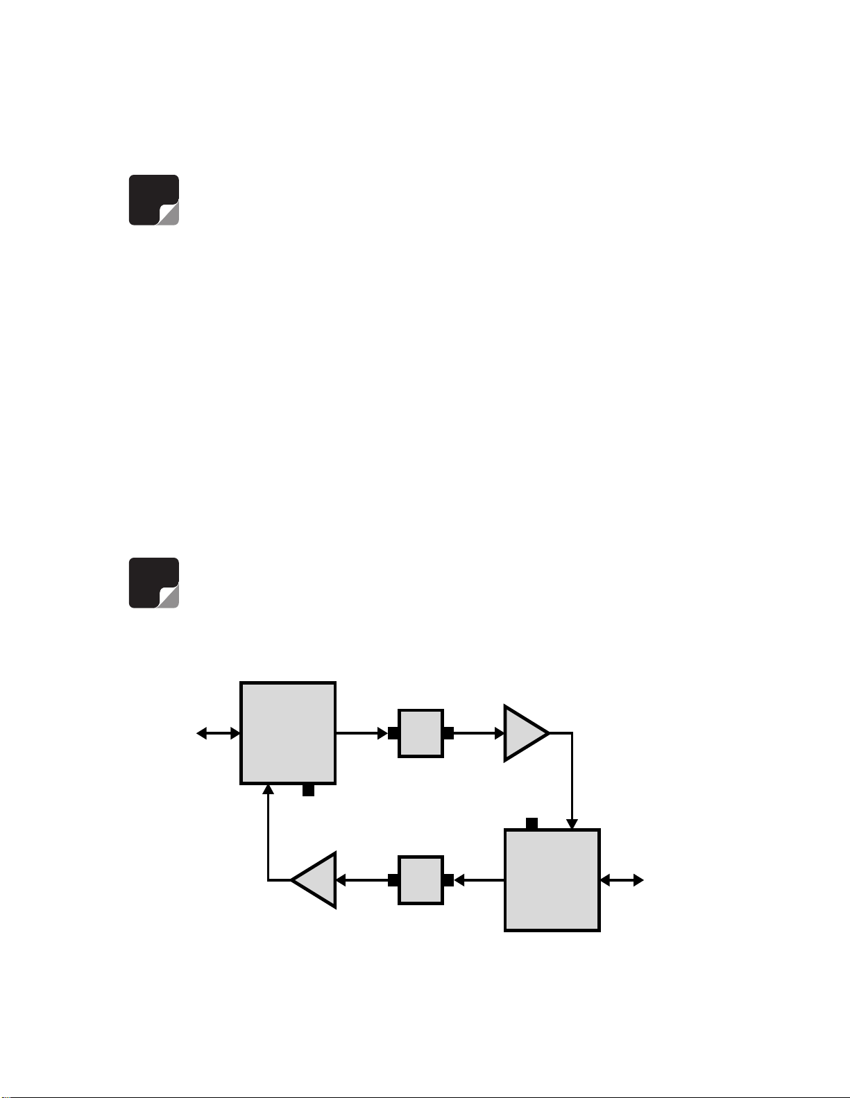
cables with the new ones. A simplified block diagram for a Non-18 MHz SB II system is shown in
Figure 1. The parts to be swapped out are indicated.
All work should be performed by a qualified electronics technician familiar with the communications
system. Refer to the system drawings at the back
of this manual as a guide to the correct placement
of assemblies and cables. Follow the instructions
listed below in a step-by-step fashion.
1) Open the signal booster enclosure and turn
OFF the AC power. Disconnect or turn OFF any
battery back-up DC input.
2) Disconnect three cables from the two filters on
the right side of the cabinet. Disconnect the
cables at the filter. Two of cables run to a teeconnector and one of the cables runs to the
card cage.
3) Disconnect the signal sampler from the filter.
The right side filters should be ready for
removal at this point.
4) Disconnect three cables from the two filters on
the left side of the cabinet. Disconnect the
Signal
To
Cabinet
Connector
Sampler
Filter Filter
Replace Filters,
Cables and Tees
Filter Filter
Test
Por t
Amp
Circulator
Circulator
Amp
Test
Por t
Signal
Sampler
Replace Filters,
Cables and Tees
Figure 1: Simplified block diagram of the Non-18 MHz SB II system.
TXRX Systems Inc. Manual 7-9424-1 07/24/06 Page 1
To
Cabinet
Connector
Page 8
cables at the filter. Two of cables run to a teeconnector and one of the cables runs to the
card cage.
7) Install the replacement filters in reverse order
making sure that the mounting plates are firmly
attached to the cabinet.
Rebanding 3 MHz systems. SB II
NOTE
filter is mounted horizontally at the top of the
cabinet. If you are rebanding a 3 MHz system to
a higher bandwidth system then the extra filter
will be removed permanently. Disconnect and
discard the cable between the left side preselector and the extra filter.
5) Disconnect the signal sampler from the left side
filter. The two left side filters should be ready for
removal at this point.
6) Remove the screws which hold the filter mounting plates to the cabinet mounting panel and
remove the filter assemblies from the cabinet.
Use care when removing the filters so as not to
damage any of the cables that are dangling in
the cabinet.
NOTE
systems with an original 3 MHz
bandwidth use an extra filter in
series with the preselector on the
left side of the cabinet. This extra
Rebanding 3 MHz systems. The
extra filter should be removed from
the cabinet first to provide additional room to maneuver the
remaining filters out of the cabinet.
8) Reconnect three cables to the two filters on the
right side of the cabinet. Reconnect the cables
at the filter. Two of the cables run to a tee-connector and one of the cables runs to the card
cage.
9) Reconnect the signal sampler to the right side
filter.
10) Reconnect three cables to the two filters on the
left side of the cabinet. Reconnect the cables
at the filter. Two of the cables run to a tee-connector and one of the cables runs to the card
cage.
11) Reconnect the signal sampler to the left side
filter.
12) Verify that all filters and cables have been rein-
stalled properly, the booster should look
exactly as it did before installing the rebanding
kit.
13) Energize the booster and verify correct opera-
tion.
Circulator
Amp
To
Cabinet
Duplexer
Connector
Signal
Signal
Sampler
Sampler
To
Duplexer
Cabinet
Connector
Amp
Figure 2: Simplified block diagram of the 18 MHZ SB II system.
TXRX Systems Inc. Manual 7-9424-1 07/24/06 Page 2
Circulator
Page 9

Procedure for 18 MHz Systems
Re-banding kits for systems that originally left the
factory as 18 MHz systems will consist of replacement filters which have the new desired bandwidth,
new tee-connectors, several critical length cables,
as well as a signal sampler. The filters are pretuned at the factory so the position of the tuning
rods should not be changed. The conversion process consists of simply replacing the old filters
(duplexer assemblies) with new filters, adding teeconnectors, cables, and signal samplers. In addition, the circulators will be attached to the cabinet
mounting plate instead of the duplexer assemblies.
A simplified block diagram for a 18 MHz SB II system is shown in Figure 2. Note that the original
duplexer assembly has the tee-connector, critical
length cables, and signal sampler built-in. The rebanding kit includes these parts as individual
assemblies.
All work should be performed by a qualified electronics technician familiar with the communications
system. Refer to the system drawings at the back
of this manual as a guide to the correct placement
of assemblies and cables. Follow the instructions
listed below in a step-by-step fashion.
7) Install the tee-connectors and associated
cables to the bottom connectors on the right
and left side filters. Refer to the appropriate system drawing in the rear of this manual to make
sure you have the correct cables going to the
correct ports. These are length sensitive cables
so it is important to connect them correctly.
Install the 2 thru-hole connectors at the bottom
of the cabinet.
8) Attach the card cage to the right and left filters
with the supplied cables.
9) Attach the signal samplers to the filters as
shown in the drawing.
10) Install the two circulators on the cabinet mount-
ing plate as shown in the drawing.
11) Install cables from the circulators to the power
amps and from the circulators to the signal
samplers.
12) Verify that all filters and cables have been
installed properly. The booster should now
look like the system drawing.
1) Open the signal booster enclosure and turn
OFF the AC power. Disconnect or turn OFF any
battery back-up DC input.
2) Disconnect and discard the 3 cables connected
to the right and left side duplexer assembly.
Including the thru-hole connectors at the bottom
of the cabinet.
3) Disconnect and discard the remaining cable
connected to the right and left side circulators.
4) Remove the mounting screws for the right and
left side duplexer assemblies and remove them,
with the attached circulators from the cabinet.
Use care when removing the duplexer assemblies so as not to damage any of the cables that
are still in the cabinet.
5) Remove the circulators from the duplexer
assemblies, they will be re-used.
6) Install the right and left side replacement filters
(two on each side) making sure that the mounting plates are firmly attached to the cabinet.
13) Energize the booster and verify correct operation.
TXRX Systems Inc. Manual 7-9424-1 07/24/06 Page 3
Page 10

TXRX Systems Inc. Manual 7-9424-1 07/24/06 Page 4
Page 11

TXRX Systems Inc. Manual 7-9424-1 07/24/06 Page 5
Page 12

TXRX Systems Inc. Manual 7-9424-1 07/24/06 Page 6
Page 13

TXRX Systems Inc. Manual 7-9424-1 07/24/06 Page 7
Page 14

TXRX Systems Inc. Manual 7-9424-1 07/24/06 Page 8
Page 15

TXRX Systems Inc. Manual 7-9424-1 07/24/06 Page 9
Page 16

TXRX Systems Inc. Manual 7-9424-1 07/24/06 Page 10
Page 17

TXRX Systems Inc. Manual 7-9424-1 07/24/06 Page 11
Page 18

2 - PLACES, EA. MTD.
WITH (2) 8 - 32 x 5/8"
#8 WASHER No. 8-20393
AND (2) #8 SPLIT
WASHERS No. 8-20394
HANDLE No. 8-20358
B.H.M.S. No. 8-6757, (2)
#8 SPLIT
WASHER
Output
3-20543
Input
4 - 40 x 1/4" P.H.M.S.
PRESELECTOR No. 3-12975,
MTD. TO MT. BRACKET
PART No. 1-20382 WITH (3)
No. 8-7370 & THEN MTD. TO
3-20544
WITH (14) 6 - 32 x 1/2"
POWER AMP ASS'Y.
PART No. 3-20028, MTD.
PANEL WITH (4) 6 - 32 x 3/8"
B.H.M.S. PART No. 8-6001
B.H.M.S. No. 8-6727 &
(14) #6 SPLIT WASHERS
PART No. 8-6750
PRESELECTOR No. 3-12975,
MTD. TO MT. BRACKET
RF IN
3-19961
RF IN
4 - 40 x 1/4" P.H.M.S.
PART No. 1-20381 WITH (3)
No. 8-7370 & THEN MTD. TO
PANEL WITH (5) 6 - 32 x 3/8"
B.H.M.S. PART No. 8-6001
CARD CAGE SUB- ASS'Y.
PART No. 3-21182, MTD.
3-19960
PART No. 3-19576
MID LEVEL AMP
RF OUT
STATUS
PART No. 3-20208
RF OUT
STATUS
ATTENUATOR
DOWNLINK OLC
INC.
SYSTEMS
TX RX
ANGOLA, N. Y. 14006
8625 INDUSTRIAL PARKWAY
WITH (14) 6 - 32 x 3/8"
P.H.M.S. No. 8-18492 &
(14) #6 SPLIT WASHER
PART No. 8-6750
*SEE DETAIL 'D' ON
PAGE 2
3-20036
UPLINK OLC
KC
SM
KAS
5-24-05
3-21-06
11-28-05
SCALE: 1" = 2"
#23099
#A23172
#A23257
Change No.
A
B
C
Rev. Date Initiator
A MEMBER OF BIRD TECHNOLOGIES GROUP
TEE CONNECTOR
PART No. 8-5855
3-0489
on Page 2
See Detail 'E'
.XX ± .01
.XXX ± .005
.XXXX ± .0005
TOLERANCES, UNLESS
OTHERWISE SPECIFIED
2 - PLACES
POWER JUNCTION BOX
PART No. 3-20197, MTD.
3-7310
ANGLES ± 1°
FILLETS .005 − .040
PLATING OR COATING.
80 FINISH ALL OVER.
DIMENSIONS APPLY AFTER
BREAK ALL EDGES .005 MIN.
ALL DIMENSIONS ARE IN INCHES.
ALL PARTS TO BE FREE OF BURRS.
WITH (2) 10 - 32 x 3/8"
*SEE DETAIL 'E' ON
PAGE 2
P.H.M.S. No. 8-6369 &
(2) #10 SPLIT WASHER
PART No. 8-6163
3-15515
AC In
5-24-05
5-24-05
BCW
BCW
Engineered By:
Designed By:
5-24-05
5-25-05
BW
KAS
Detailed By:
Drawn By:
SUPPLIED WITH
HARDWARE
ON PAGE 2.
*SEE DETAIL ' C'
UpLink In
HOLE COVER
EMI/RFI FILTER
PART No. 8-20847, MTD.
DIAGRAM FOR
SIGNAL BOOSTER II
ASSEMBLY & CABLING
Title:
Checked By:
ENCLOSURE.
DownLin k Out
ENCLOSURE
SUPPLIED WITH
2 - PLACES
WITH (2) 8 - 32 x 3/8"
T.H.M.S. No. 8-18254 &
(2) 8 - 32 KEPNUTS
PART No. 8-6017
*SEE DE TAIL ' F' ON
C
Rev.
(Page 1 of 2)
3-20405
61-89A-50-C10-(XX)
Drawing No.
SEE 6-20 405 FOR SPECIFICATION S
PAGE 2
ARE SUPPLIED WITH ENC.
MOUNT PANEL No. 1-20225
MTD. WITH (8) FULLY
THREADED 10 - 32 x 7/16"
FLAT HEAD S.H.C.S.
(TX RX No. 8-20449) WHICH
TO PANEL WITH (3) 4 - 40 x 5/16"
800-900 MHz ISOLATOR No. 8-20113
2 - PLACES, EA. MTD. TO BRACKET
No. 1-20086 WITH (2) m2 x.4X 6mm
P.H.M.S. No. 8-20210 & THEN MTD.
P.H.M.S. No. 8-6154
ENCLOSURE
PART No. 1-20164 (-G1)
(PAINTED STEEL)
PART No. 1-20372 (-G2)
(STAINLESS STEEL)
3-20578
PART No. 3-19804
FACEPLATE ASS'Y.
PART No. 3-20208
3-20544
Output
Input
2 - PLACES
SAMPLER ASS'Y.
PART No. 3-3060
RF IN
RF IN
ATTENUATOR
RF OUT
3-19961
PART No. 3-19576
RF OUT
MID LEVEL AMP
STATUS
DL PA
STATUS
12v UL PA
24v
3-20578
3-19960
Red & Blac k Wires
Blk
Red
Cancel
3-20035
Enter
STRAIN RELIEF
3-20037
No. 8-20111
Brown
N
Orange
Green
Brown
Blue
Yellow
White
3-0489
3-20034
3-7310
3-20869
Blue
3-20868
CAPACITIVE FILTER
PART No. 3-20989, MTD.
WITH (1) 4 - 40 x 1/4"
B.H.M.S. No. 8-7438
PAGE 2
*SEE DETAIL 'A' ON
2-POSITION TERMINAL
WITH (1) 4 - 40 x 3/4"
STRIP No. 8-19999, MTD.
Black
Red
Grn/Ylw
+SFG+V -V -S L
6-POSITION TERMINAL
P.H.M.S. No. 8-6721
STRIP No. 8-20000, MTD.
WITH (3) 4 - 40 x 3/4"
P.H.M.S. No. 8-6721
FLAT WASHER
PART No. 1-2743
2 - PLACES
3-15515
3-20543
MTD. TO MT. BRACKET
4 - 40 x 1/4" P.H.M.S.
No. 8-7370 & THEN MTD. TO
PRESELECTOR No. 3-12975,
PART No. 1-20381 WITH (3)
POWER AMP ASS'Y.
B.H.M.S. PART No. 8-6001
PANEL WITH (5) 6 - 32 x 3/8"
PART No. 3-19787, MTD.
WITH (14) 6 - 32 x 1/2"
B.H.M.S. No. 8-6727 &
(14) #6 SPLIT WASHERS
PART No. 8-6750
PRESELECTOR No. 3-12975,
MTD. TO MT. BRACKET
PART No. 1-20382 WITH (3)
4 - 40 x 1/4" P.H.M.S.
No. 8-7370 & THEN MTD. TO
PANEL WITH (4) 6 - 32 x 3/8"
B.H.M.S. PART No. 8-6001
4-WAY BACKED MT.
WITH WIRE TIE
PART No. 8-6322
PART No. 8-6112
POWER SUPPLY MODULE
PART No. 8-20667, MTD. TO
MT. BRACKET No. 1-20673
WITH (3) M4 x 8mm P.H.M.S.
No. 8-18530 & THEN MTD. TO
PANEL WITH (2) 6 - 32 x 3/8"
P.H.M.S. No. 8-18492 & (2)
#6 SPLIT WASHERS No. 8-6750
GROUNDING STRAP No. 8-20120
' ON PAGE 2
USING H ARDWARE SUPPL IED
*SEE DETAIL 'B
STUD ON ENCLOSURE & DOOR
WITH ENCLOSURE
TO BE ATTACHED TO GROUND
DownLin k In
2 - PLACES
LOCKWASHER
PART No. 8-6791
UpLink Out
TXRX Systems Inc. Manual 7-9424-1 07/24/06 Page 12
Page 19

TXRX Systems Inc. Manual 7-9424-1 07/24/06 Page 13
Page 20

TXRX Systems Inc. Manual 7-9424-1 07/24/06 Page 14
Page 21

TXRX Systems Inc. Manual 7-9424-1 07/24/06 Page 15
Page 22

TXRX Systems Inc. Manual 7-9424-1 07/24/06 Page 16
Page 23

TXRX Systems Inc. Manual 7-9424-1 07/24/06 Page 17
Page 24

TXRX Systems Inc. Manual 7-9424-1 07/24/06 Page 18
Page 25

TXRX Systems Inc. Manual 7-9424-1 07/24/06 Page 19
Page 26
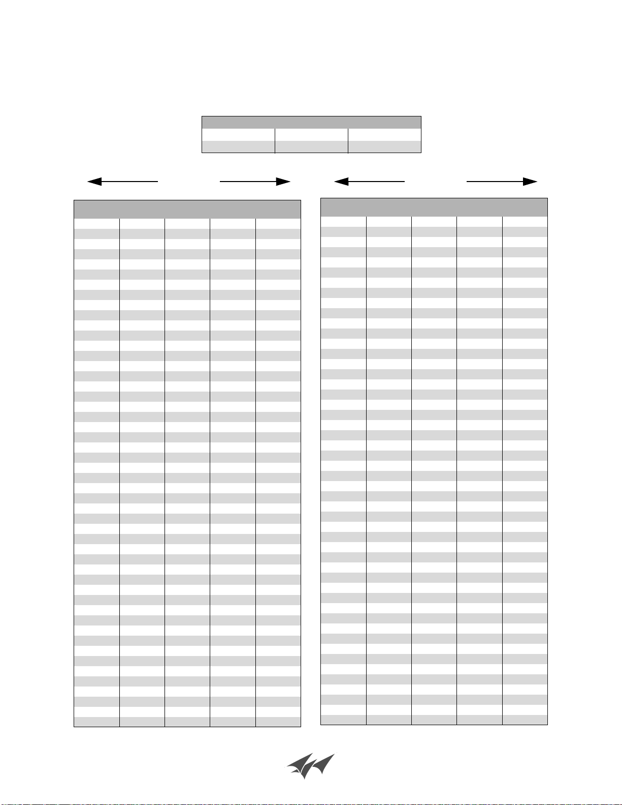
Power Ratio and Voltage Ratio to Decibel
Conversion Chart
Loss or Gain Power Ratio Voltage Ratio
+9.1 dB 8.128 2.851
-9.1 dB 0.123 0.351
- dB +- dB +
Voltage
Ratio
1 1 0 1 1
0.989 0.977 0.1 1.012 1.023
0.977 0.955 0.2 1.023 1.047
0.966 0.933 0.3 1.035 1.072
0.955 0.912 0.4 1.047 1.096
0.944 0.891 0.5 1.059 1.122
0.933 0.871 0.6 1.072 1.148
0.923 0.851 0.7 1.084 1.175
0.912 0.832 0.8 1.096 1.202
0.902 0.813 0.9 1.109 1.23
0.891 0.794 1 1.122 1.259
0.881 0.776 1.1 1.135 1.288
0.871 0.759 1.2 1.148 1.318
0.861 0.741 1.3 1.161 1.349
0.851 0.724 1.4 1.175 1.38
0.841 0.708 1.5 1.189 1.413
0.832 0.692 1.6 1.202 1.445
0.822 0.676 1.7 1.216 1.479
0.813 0.661 1.8 1.23 1.514
0.804 0.646 1.9 1.245 1.549
0.794 0.631 2 1.259 1.585
0.785 0.617 2.1 1.274 1.622
0.776 0.603 2.2 1.288 1.66
0.767 0.589 2.3 1.303 1.698
0.759 0.575 2.4 1.318 1.738
0.75 0.562 2.5 1.334 1.778
0.741 0.55 2.6 1.349 1.82
0.733 0.537 2.7 1.365 1.862
0.724 0.525 2.8 1.38 1.905
0.716 0.513 2.9 1.396 1.95
0.708 0.501 3 1.413 1.995
0.7 0.49 3.1 1.429 2.042
0.692 0.479 3.2 1.445 2.089
0.684 0.468 3.3 1.462 2.138
0.676 0.457 3.4 1.479 2.188
0.668 0.447 3.5 1.496 2.239
0.661 0.437 3.6 1.514 2.291
0.653 0.427 3.7 1.531 2.344
0.646 0.417 3.8 1.549 2.399
0.638 0.407 3.9 1.567 2.455
0.631 0.398 4 1.585 2.512
0.624 0.389 4.1 1.603 2.57
0.617 0.38 4.2 1.622 2.63
0.61 0.372 4.3 1.641 2.692
0.603 0.363 4.4 1.66 2.754
0.596 0.355 4.5 1.679 2.818
0.589 0.347 4.6 1.698 2.884
0.582 0.339 4.7 1.718 2.951
0.575 0.331 4.8 1.738 3.02
0.569 0.324 4.9 1.758 3.09
Power
Ratio
dB
Voltage
Ratio
Power
Ratio
Voltage
Ratio
0.562 0.316 5 1.778 3.162
0.556 0.309 5.1 1.799 3.236
0.55 0.302 5.2 1.82 3.311
0.543 0.295 5.3 1.841 3.388
0.537 0.288 5.4 1.862 3.467
0.531 0.282 5.5 1.884 3.548
0.525 0.275 5.6 1.905 3.631
0.519 0.269 5.7 1.928 3.715
0.513 0.263 5.8 1.95 3.802
0.507 0.257 5.9 1.972 3.89
0.501 0.251 6 1.995 3.981
0.496 0.246 6.1 2.018 4.074
0.49 0.24 6.2 2.042 4.169
0.484 0.234 6.3 2.065 4.266
0.479 0.229 6.4 2.089 4.365
0.473 0.224 6.5 2.113 4.467
0.468 0.219 6.6 2.138 4.571
0.462 0.214 6.7 2.163 4.677
0.457 0.209 6.8 2.188 4.786
0.452 0.204 6.9 2.213 4.898
0.447 0.2 7 2.239 5.012
0.442 0.195 7.1 2.265 5.129
0.437 0.191 7.2 2.291 5.248
0.432 0.186 7.3 2.317 5.37
0.427 0.182 7.4 2.344 5.495
0.422 0.178 7.5 2.371 5.623
0.417 0.174 7.6 2.399 5.754
0.412 0.17 7.7 2.427 5.888
0.407 0.166 7.8 2.455 6.026
0.403 0.162 7.9 2.483 6.166
0.398 0.159 8 2.512 6.31
0.394 0.155 8.1 2.541 6.457
0.389 0.151 8.2 2.57 6.607
0.385 0.148 8.3 2.6 6.761
0.38 0.145 8.4 2.63 6.918
0.376 0.141 8.5 2.661 7.079
0.372 0.138 8.6 2.692 7.244
0.367 0.135 8.7 2.723 7.413
0.363 0.132 8.8 2.754 7.586
0.359 0.129 8.9 2.786 7.762
0.355 0.126 9 2.818 7.943
0.351 0.123 9.1 2.851 8.128
0.347 0.12 9.2 2.884 8.318
0.343 0.118 9.3 2.917 8.511
0.339 0.115 9.4 2.951 8.71
0.335 0.112 9.5 2.985 8.913
0.331 0.11 9.6 3.02 9.12
0.327 0.107 9.7 3.055 9.333
0.324 0.105 9.8 3.09 9.55
0.32 0.102 9.9 3.126 9.772
Power
Ratio
dB
Voltage
Ratio
Power
Ratio
Bird Technologies Group TX RX Systems Inc.
Page 27

Return Loss vs. VSWR
Watts to dBm
Return Loss VSWR
30 1.06
25 1.11
20 1.20
19 1.25
18 1.28
17 1.33
16 1.37
15 1.43
14 1.50
13 1.57
12 1.67
11 1.78
10 1.92
9 2.10
Watts dBm
300 54.8
250 54.0
200 53.0
150 51.8
100 50.0
75 48.8
50 47.0
25 44.0
20 43.0
15 41.8
10 40.0
5 37.0
4 36.0
3 34.8
2 33.0
1 30.0
dBm = 10log P/1mW
Where P = power (Watt)
Insertion Loss
Input Power (Watts)
50 75 100 125 150 200 250 300
3 25 38 50 63 75 100 125 150
2.5 28 42 56 70 84 112 141 169
2 32 47 63 79 95 126 158 189
1.5 35 53 71 88 106 142 177 212
1 40 60 79 99 119 159 199 238
Insertion Loss
.5 45 67 89 111 134 178 223 267
Output Power (Watts)
Free Space Loss
Distance (miles)
.25 .50 .75 1 2 5 10 15
150 68 74 78 80 86 94 100 104
220 71 77 81 83 89 97 103 107
460 78 84 87 90 96 104 110 113
860 83 89 93 95 101 109 115 119
940 84 90 94 96 102 110 116 120
Frequency (MHz)
1920 90 96 100 102 108 116 122 126
Free Space Loss (dB)
Free space loss = 36.6 + 20log D + 20log F
Where D = distance in miles and F = frequency in MHz
Bird Technologies Group TX RX Systems Inc.
Page 28

8625 Industrial Parkway, Angola, NY 14006 Tel: 716-549-4700 Fax: 716-549-4772 sales@birdrf.com www.bird-technologies.com
 Loading...