

Page 1
Part No
.
YOU'RE HEARD, LOUD AND CLEAR.
Installation and Operation Manual
for the Two-Way Signal Booster System
Model Number 61-89A-50-XXX-XX
Copyright © 2005 TX RX Systems Inc.
First Printing: March 2004
7-9362-2
Version Number Version Date
1 03/30/04
1.2 04/15/04
2 10/19/05
8625 Industrial Parkway, Angola, NY 14006 Tel: 716-549-4700 Fax: 716-549-4772 sales@birdrf.com www.bird-technologies.com
Page 2
Warranty
This warranty applies for one year from shipping date.
TX RX Systems Inc. warrants its products to be free from defect in material and workman-
ship at the time of shipment. Our obligation under warranty is limited to replacement or
repair, at our option, of any such products that shall have been defective at the time of
manufacture.
TX RX Systems Inc. reserves the right to replace with merchandise of equal performance
although not identical in every way to that originally sold.
TX RX Systems Inc. is not liable for damage caused by lightning or other natural disasters.
No product will be accepted for repair or replacement without our prior written approval.
The purchaser must prepay all shipping charges on returned products. TX RX Systems
Inc. shall in no event be liable for consequential damages, installation costs or expense of
any nature resulting from the purchase or use of products, whether or not they are used in
accordance with instructions. This warranty is in lieu of all other warranties, either expressed or implied, including any implied warranty or merchantability of fitness. No representative is authorized to assume for TX RX Systems Inc. any other liability or warranty
than set forth above in connection with our products or services.
Terms and Conditions of Sale
Symbols
Commonly Used
WARNING
CAUTION or
ATTENTION
High Voltage
PRICES AND TERMS: Prices are FOB seller’s plant in Angola, NY domestic packaging
only, and are subject to change without notice. Federal, State and local sales or excise
taxes are not included in prices. When Net 30 terms are applicable, payment is due
within 30 days of invoice date. All orders are subject to a $100.00 net minimum.
QUOTATIONS: Only written quotations are valid.
ACCEPTANCE OF ORDERS: Acceptance of orders is valid only when so acknowledged
in writing by the seller.
SHIPPING: Unless otherwise agreed at the time the order is placed, seller reserves the
right to make partial shipments for which payment shall be made in accordance with
seller’s stated terms. Shipments are made with transportation charges collect unless
otherwise specified by the buyer. Seller’s best judgement will be used in routing, except
that buyer’s routing is used where practicable. The seller is not responsible for selection
of most economical or timeliest routing.
CLAIMS: All claims for damage or loss in transit must be made promptly by the buyer
against the carrier. All claims for shortages must be made within 30 days after date of
shipment of material from the seller’s plant.
SPECIFICATION CHANGES OR MODIFICATIONS: All designs and specifications of
seller’s products are subject to change without notice provided the changes or modifications do not affect performance.
RETURN MATERIAL: Product or material may be returned for credit only after written
authorization from the seller, as to which seller shall have sole discretion. In the event
of such authorization, credit given shall not exceed 80 percent of the original purchase.
In no case will Seller authorize return of material more than 90 days after shipment from
Seller’s plant. Credit for returned material is issued by the Seller only to the original
purchaser.
ORDER CANCELLATION OR ALTERATION: Cancellation or alteration of acknowledged
orders by the buyer will be accepted only on terms that protect the seller against loss.
NON WARRANTY REPAIRS AND RETURN WORK: Consult seller’s plant for pricing.
Buyer must prepay all transportation charges to seller’s plant. Standard shipping policy
set forth above shall apply with respect to return shipment from TX RX Systems Inc. to
buyer.
NOTE
Use Safety
Glasses
ESD
Electrostatic
Discharge
Hot Surface
Electrical Shock
Hazard
Important
Information
Disclaimer
Product part numbering in photographs and drawings is accurate at time of printing.
Part number labels on TX RX products supercede part numbers given within this manual.
Information is subject to change without notice.
Page 3
WARNING
For Class A Unintentional Radiators
WARNING
This equipment has been tested and found to comply with the limits for a Class A digital device, pursuant to
part 15 of the FCC rules. These limits are designed to provide reasonable protection against harmful interference when the equipment is operated in a commercial environment. This equipment generates, uses,
and can radiate radio frequency energy and, if not installed and used in accordance with the instruction
manual, may cause harmful interference to radio communications. Operation of this equipment in a residential area is likely to cause harmful interference in which case the user will be required to correct the
interference at his own expense.
Changes or modifications not expressly approved by TX
RX System Inc. could void the user’s authority to operate
the equipment.
This device complies with Part 15 of the FCC Rules. Operation is subject to the
following two conditions: (1) this device may not cause harmful interference and
(2) this device must accept any interference received, including interference
that may cause undesired operation.
To satisfy FCC RF exposure requirements for mobile transmitting devices, a separation distance of 1.0 Meters or more
should be maintained between the UPLINK antenna of this
device and persons during device operation. To satisfy FCC
RF exposure requirements for mobile transmitting devices, a
separation distance of 0.2 Meters or more should be maintained between the DOWNLINK antenna of this device and
persons during device operation. To ensure compliance,
operations at closer than these distances is not recommended.
The antenna used for this transmitter must not be co-located
in conjunction with any other antenna or transmitter.
Page 4

Antenna System Installation
The antenna or signal distribution system consists of two branches. An uplink
branch typically uses an outdoor mounted, unidirectional gain antenna such
as a yagi and a downlink signal radiating system consisting of a network of
zero-gain whip antennas or lengths of radiating cable usually mounted inside
of the structure.
Even though the antenna system may not be supplied or installed by TX RX
Systems. The following points need to be observed because both the safety
of the user and proper system performance depend on them.
1) Antenna system installation should only be performed by qualified technical personnel.
2) The following instructions for your safety describe antenna installation
guidelines based on FCC Maximum RF Exposure Compliance requirements.
3) The uplink antenna is usually mounted outside and exchanges signals
with the repeater base station or donor site. It is typically mounted permanently-attached to the building wall or roof. The gain of this antenna should
NOT exceed 10 dB. Only qualified personnel should have access to the
antenna and under normal operating conditions, no one should be able to
touch or approach it within 1 meter (40 inches).
4) The downlink or in-building signal distribution system is connected to the
downlink booster port using coaxial cable. The distribution system may
use radiating coaxial cable or a network 1/4 wave whip antennas whose
gain does not exceed 0 dB for any radiator. These antennas should be
installed so that the user cannot approach any closer than 0.2 meters (8
inches) from the antenna.
Page 5

Table of Contents
General Description .............................................................................................. 1
Unpacking .......................................................................................................1
Installation .......................................................................................................1
Location .......................................................................................................1
Mounting .......................................................................................................2
Connections .......................................................................................................4
AC Line .......................................................................................................4
Backup DC Power.................................................................................................. 4
Alarm Terminals (Form-C Contacts) ...................................................................... 4
RF Connections ..................................................................................................... 5
Pre-RF Connection Tests......................................................................................5
Test Equipment ...................................................................................................... 5
Antenna Isolation ................................................................................................... 5
Procedure for Measuring Antenna Isolation .......................................................... 5
Increase isolation or decrease gain?..................................................................... 6
Normal Operation .................................................................................................. 6
LED Status Indicators ............................................................................................ 7
Front Panel LED’s ................................................................................................ 7
Module LED’s ...................................................................................................... 7
OLC Light Bars .................................................................................................... 7
Front Panel Controls & the LCD Display................................................................7
LCD Screen ....................................................................................................... 7
Configuration Settings ........................................................................................... 9
Restore Original Configuration ........................................................................... 9
Calibrate Currents .............................................................................................. 9
Set Gain .......................................................................................................9
Set Output Level ................................................................................................. 9
Change Gain Configuration ................................................................................9
Detailed Status Screens ........................................................................................ 10
Amplifiers .......................................................................................................10
Power Supply...................................................................................................... 10
OLC .......................................................................................................10
OLC Datalog ....................................................................................................... 10
Alarms .......................................................................................................10
LED Indicators ....................................................................................................... 10
Form-C contacts .................................................................................................... 11
Performance Survey..............................................................................................11
Maintenance and Repair ....................................................................................... 12
Power Amplifier Replacement................................................................................ 14
Module Replacement.............................................................................................14
Display/User Interface Replacement .....................................................................15
Power Supply Replacement................................................................................... 16
Duplexer / Filter Replacement ...............................................................................16
Card Cage Replacement ....................................................................................... 16
Recommended Spares .......................................................................................... 16
Table of Contents
Manual 7-9362-2 10/19/05
Page 6

Figures and Tables
Figure 1 Cabinet mounting hole layout 2
Figure 2 Front internal cabinet view 3
Figure 3 AC power entry 4
Figure 4 Measuring antenna isolation 6
Figure 5 Boot-up display 6
Figure 6 Operational status display 7
Figure 7 Menu System 8
Figure 8 Measuring Booster Gain 11
Figure 9 Performance Survey 12
Figure 10 Removing the Power Amplifier (1 of 3) 13
Figure 11 Removing the Power Amplifier (2 of 3) 13
Figure 12 Removing the Power Amplifier (3 of 3) 14
Figure 13 Disconnecting Display/User Interface 15
Table 1 Model Number Designations 1
Specifications 17
Block Diagram High Gain (1 of 4) 18
Block Diagram Med Gain (2 of 4) 19
Block Diagram Low Gain (3 of 4) 20
Block Diagram (4 of 4) 21
Celsius to Fahrenheit Conversions 22
Table of Contents
Manual 7-9362-2 10/19/05
Page 7
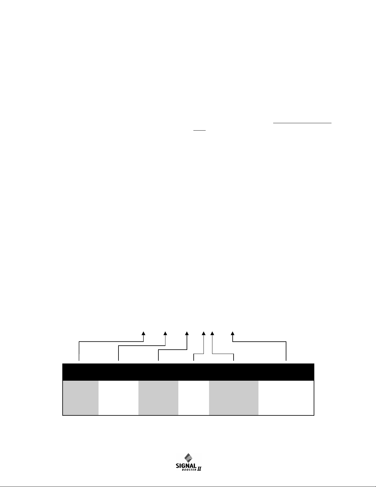
GENERAL DESCRIPTION
61 - 89A - 50 - A18 - G1
(Example)
FAMILY FREQUENCY
BAND
MODEL COARSE
GAIN
BANDWIDTH ENCLOSURE
TYPE
60 =
61 =
612 =
1 Way
2 Way
2 Way
w/Fiber
Interface
89A = 806 - 824
851 - 869
50 = Signal
Booster II
A =
B =
C =
80 dB
60 dB
45 dB
18 = 18 MHz
15 = 15 MHz
10 = 10 MHz
05 = 5 MHz
03 = 3 MHz (NPSPAC)
G1 =
G2 =
RM =
Painted, Nema4
Stainless, Nema4X
Rack Mount
Table 1: Model number designations. Model 61-89A-50-A18-G1 shown as example.
*
*
Note: Gain of 80 dB model set to 50 dB at factory. Please measure antenna isolation before resetting.
GAI
GAIN
Signal boosters extend radio coverage into areas
where abrupt propagation losses prevent reliable
communication. No frequency translation (conversion) occurs with this device. Signal Booster II (SB
II) is a broadband, bi-directional signal booster
available in a variety of configurations as shown in
Table 1. The product model number is used to
describe each configuration available. This manual
details the installation and operation of the 61-89A50-XXX-XX series of boosters.
The system can be ordered in one of three maximum gain configurations including Full Gain (+80
dB gain max), Medium Gain (+60 dB gain max),
and Low Gain (+45 dB max gain). The maximum
gain of the system is determined by the exact type
of cards plugged into the low and mid level slots as
shown in the block diagrams at the back of this
manual. The maximum gain of the uplink or downlink branch is adjustable and can be setup independently. In addition, the gain of each branch can
be reduced up to 30 dB in 0.5 dB increments via
software interface.
The bandwidth of the system is determined by the
passband of the input/output filtering. The filters
passband is determined by its physical construction so must be determined at the time of order. As
shown in table 1 the system may be ordered in any
of five different bandwidths including 18, 15, 10, 5,
and 3 MHz.
Three cabinet styles are available. The G1 suffix
denotes a NEMA-4 style cabinet which is suitable
for indoor or outdoor use. The G2 suffix denotes a
stainless steel NEMA-4X style cabinet suitable for
corrosive environments such as salt air and the RM
suffix a rack mount version which is intended for
indoor mounting only.
UNPACKING
It is important to report any visible damage to the
carrier immediately. It is the customer's responsibility to file damage claims with the carrier within a
short period of time after delivery (1 to 5 days).
Care should be taken when removing the unit from
the packing box to avoid damage to external heatsink fins. Use caution because the heatsink fins
can have somewhat sharp corners. Signal Booster
II (SB II) weighs about 85 lbs. so use enough people when lifting the unit.
INSTALLATION
The following sections discuss general considerations for installing the booster. All work should be
performed by qualified personal in accordance with
local codes.
Location
The layout of the signal distribution system will be
the prime factor in determining the mounting location of Signal Booster II. However, safety and serviceability are also key considerations. The unit
should be located where it cannot be tampered
with by the general public, yet is easily accessible
to service personnel. Also consider the weight of
Manual 7-9362-2 Page 1TX RX Systems Inc. 10/19/05
Page 8
the unit and the possibility for injur y if the unit
MOUNTING TA BS
DOOR
CLAMPS
0.438" DIA.
(12mm)
0.438" DIA.
(12mm)
SIDE VIEW
18"
(457mm)
25.25"
(641mm)
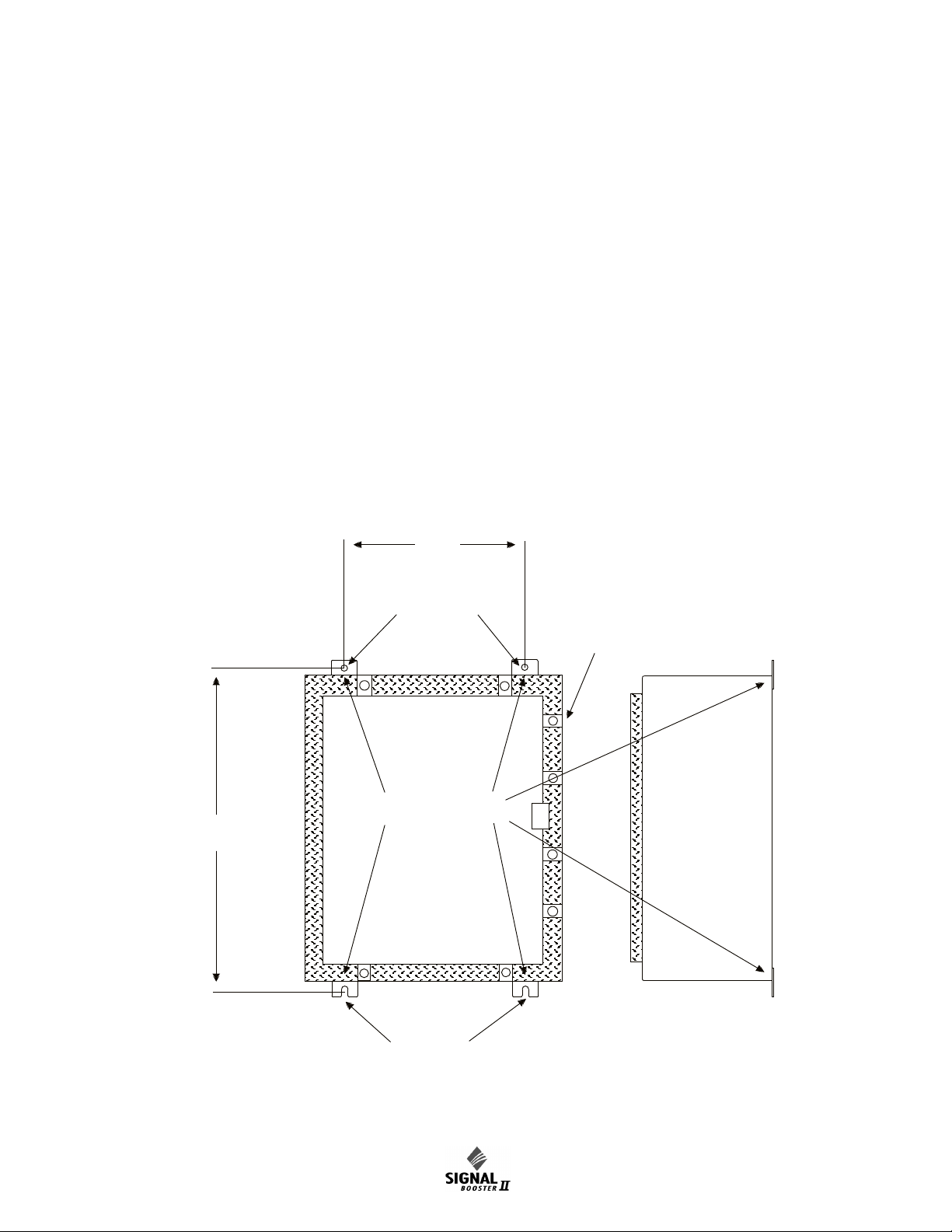
Figure 1: SB II cabinet mounting hole layout.
should become detached from its mounting surfaces for any reason.
Although signal boosters can operate for years
without being attended to, the unit will need to be
accessed by service personnel with troubleshooting equipment, such as digital multimeters and
spectrum analyzer or a laptop computer from time
to time. The location of the power source will also
have a bearing on the mounting location. SB II
uses external heat sinks and needs to be mounted
where there can be an unobstructed air flow over
the heat sinks fins. The SB II cabinet will stay warm
during normal operation so in the interest of equipme nt lon gevity, avoid locatio ns tha t carr y ho t
exhaust air or are continually hot.
Mounting
Figure 1 shows mounting hole dimensions and
layout for the cabinet. Mount the cabinet using 3/8”
(10 mm) diameter steel bolts (not supplied). We
recommend flat washers on both ends and a lock
washer under the nut. Nut and bolt mounting is
preferred to the use of lag bolts. Use backer blocks
where necessary to spread the force over a larger
surface area. In areas of known seismic activity,
additional devices such as tether lines may be necessary.
Because TX RX Systems, Inc. cannot anticipate all
the possible mounting locations and struc ture
types where these devices will be located, we recommend consulting local building inspectors, engineering consultants or architects for advice on how
to properly mount objects of this type, size and
weight in your particular situation.
Manual 7-9362-2 Page 2TX RX Systems Inc. 10/19/05
Page 9

Power Supply
AC Power
Switch
Battery
Backup
Switch
Form-C
Contacts
Connect Backup
Battery here
Uplink
Power
Duplexer
Downlink Power
Amplifier
Duplexer
Menu
Select
Buttons
Uplink M/L Card
(for Full Gain Model)
Uplink M/L Card
(for Mid Gain Model)
Uplink Low Gain Card
(for Low Gain Model)
Uplink L/L Card
(for Full Gain Model)
Attenuator Card
(for Mid Gain Model)
Attenuator Card
(for Low Gain Model)
Uplink
Power
Distribution
Downlink M/L Card
(for Full Gain Model)
Downlink M/L Card
(for Mid Gain Model)
Downlink Low Gain Card
(for Low Gain System)
Downlink L/L Card
(for Full Gain Model)
Attenuator Card
(for Mid Gain Model)
Attenuator Card
(for Low Gain Model)
Downlink
Power
Distribution
Controller
Downlink In
Uplink Out
to Donor
Antenna
Uplink Out
Downlink In
to In-building
Distribution
AC Power
Entry
Comm-Card
(Optional)
Spare
(unused slot)
OLC Light
Bars
Status LEDs
Isolator
Test Port
Isolator
Test Port
Figure 2: Front view of SB II. Model 61-89A-50-A18-G1 two-way signal booster shown as an example.
Manual 7-9362-2 Page 3TX RX Systems Inc. 10/19/05
Page 10
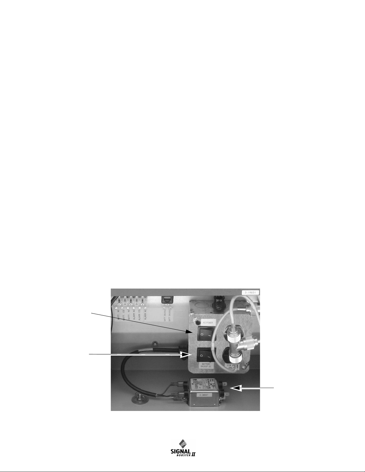
It is the customer’s responsibility to make sure
Figure 3: Wiring of AC line entry.
Connect
incoming AC
here
AC Power
Switch
Battery
Backup
Switch
these devices are mounted safely and in compliance with local building codes.
CONNECTIONS
All cabling connections to the booster should be
made and checked for correctness prior to powering up the system.
AC Line
Signal Booster II is designed to be hard-wired to
110 single phase AC lines at 50 - 60 Hz (see Fig-
ures 2 and 3). An AC line filter is provided for this
purpose. There is a hole provided in the cabinet
bottom-wall for bringing in the AC line. Fasten
quick connect plugs to the incoming AC line, then
connect the ground wire, neutral wire, and hot wire
to the respective pins on the top of the AC line filter. Refer to the photo shown in Figure 3 below.
The output of the AC line filter is wired into the
switch box which also contains a dual convenience
outlet for running test equipment. Use conduit for
running the wiring into SB II and #14 gauge or
larger conductors.
Backup DC Power
SB II may be run on a DC power source that can
supply 24 to 27 volts DC at 2.5 amps. Screw terminals are provided for this purpose (see figure 2).
This line should be equipped with a fast-acting 3
Amp fuse. Use #16 or #18 gauge wire for this connection.
The power system in SB II automatically switches
to this backup DC input when the AC supply fails
for any reason including a power outage or intentional disconnection.
It is not necessary that this connection be made for
normal operation on the AC line.
Alarm Terminals (Form-C contacts)
Two sets of contacts are provided to monitor the
gen e ral operat i n g c ondition of SB II and are
intended for connection to a supervisory system.
See figure 2.
One set changes state when the AC power supply
shuts down for any reason and the unit switches to
operation on the backup DC power system.
The other set of contacts changes state when any
of a number of fault conditions arises within the
electronics such as current drain outside of the
expected operating range in some module.
A six-terminal strip is provided for the interface and
uses screw terminals for ease of connection. Route
the alarm wires through one of the access holes in
the bottom of the box, strip about 3/16” of insulation from each end, loosen the screw terminal,
insert and retighten. Use #20 or #22 gauge insulated wire.
Manual 7-9362-2 Page 4TX RX Systems Inc. 10/19/05
Page 11

Use of these terminals is optional. SB II also has a
NOTE
number of status LEDs built-in to individual modules to indicate a fault condition.
RF Connections
N(F) bulkhead connectors are provided on the bottom of the cabinet for connection to the signal distribution system. Be sure that the correct branch of
the distribution system is connected to its corresponding Uplink/Downlink connector or the system
will not work properly. Using high-quality connectors with gold center pin s is a dvised. Flexible
jumper cables made of high-quality coax are also
acceptable for connecting to rigid cable sections.
CAUTION: The maximum RF input
power level for the SBII is -15 dBm.
Stronger input signals will cause the
unit to exceed it’s IM specifications.
Input signals stronger than 0 dBm
will physically damage the unit.
Antenna Isolation
Just like the feedback squeal that can occur when
the microphone and speaker get too close to each
other in a public address system, a signal booster
can start to self oscillate. This can occur when the
is olation b etween th e inp ut antenn a or signal
source and the output distribution system does not
exceed the signal boosters gain by at least 15 dB.
Oscillation will reduce the effectiveness of the system and may possibly damage the power amplifier
stages.
In general, if one or both antenna ports are connected to sections of radiating coaxial cable (lossy
cable) the isolation will be more than adequate
because of the high coupling loss values that are
encountered with this type of cable. When a network of antennas are used for the input and output,
this problem is much more likely. Isolation values
are relatively easy to measure with a spectrum
analyzer and signal generator.
PRE-RF CONNECTION TESTS
Antenna isolation between the uplink and downlink
branches should be measured before connecting
the signal booster to the antenna system. This step
is necessary to insure that no conditions exist that
could possibly damage the signal booster and
should not be skipped for even the most thoroughly
designed system.
Note: The 80 dB gain models are factory preset to 50 dB gain and should
only be reset to a higher value after
determining the safe maximum gain
based on antenna isolation
Test Equipment
The following equipment is required in order to perform the pre-installation measurements.
1) Signal generator for the frequencies of interest
capable of a 0 dBm output level. Modulation is
not necessary.
2) Spectrum analyzer that covers the frequencies
of interest and is capable of observing signal
levels down to -100 dBm or better.
3) Double shielded coaxial test cables made from
RG142, RG55 or RG223 coaxial cable.
Procedure for Measuring Antenna Isolation
1) Set the signal generator for a 0 dBm output
level at the center frequency of one of the signal
boosters passbands (815 or 860 MHz)
2) Set the spectrum analyzer for the same center
frequency and a sweep width equal to or just
slightly greater than the passband (18 MHz)
chosen in step one.
3) Connect the test leads of the signal generator
and the spectrum analyzer together using a
female barrel connector, see Figure 4. Observe
the signal on the analyzer and adjust the input
attenuator of the spectrum analyzer for a signal
level that just reaches the 0 dBm level at the top
of the graticule.
4) Referring to figure 4, connect the generator test
lead to one side of the signal distribution system
(external antenna) and the spectrum analyzer
lead to the other (internal distribution system)
and observe the signal level. The difference
between this observed level and 0 dBm is the
isolation between the sections. If the signal is
too weak to observe, the spectrum analyzer's
bandwidth may have to be narrowed and its
input attenuation reduced. Record the isolation
value. The isolation value measured should
exceed the signal booster’s gain figure by at
least 15 dB.
Manual 7-9362-2 Page 5TX RX Systems Inc. 10/19/05
Page 12

It is wise to repeat the procedure listed above for
INTERNAL
SIGNAL DISTRIBUTION
SYSTEM
SPECTRUM
ANALYZER
EXTERNAL
ANTENNA
SIGNAL
GENERATOR
ZERO LOSS
REFERENCE
ISOLATION (dB)
Figure 4: Typical test equipment interconnection for measuring antenna isolation.
Figure 5: Software version is displayed briefly
during the boot-up sequence.
measuring antenna isolation with the signal generator set to frequencies at the passbands edges in
order to see if the isolation is remaining relatively
constant over the complete width of the passband.
determined in step 1. A detailed explanation of
how to negotiate the menu system is given on
page 8.
3) Repeat step 2 for the downlink path.
Repeat the isolation measurements at the other
passband in bi-directional systems and use the
lesser of the two values to determine the maximum
gain setting.
Increase Isolation or decrease gain?
Modification of the signal distribution system is
required to increase isolation between the up and
downlink path. This will require significant changes
that may or may not be practical from a cost or
logistical standpoint. Gain reduction may be the
only alternative but this is easy to achieve with Signal Booster II. Gain for both the uplink and downlink path can be set from 50 to 80 dB. Here are the
steps to follow.
1) Subtract 15 dB from the measured isolation
between uplink and downlink branches of the
antenna/signal distribution system. This is the
maximum usable gain level for both the uplink
and downlink path.
2) Accessing the user menu through the front
panel, set the gain of the uplink path to the level
NORMAL OPERATION
Power is applied to the signal booster by turning on
the AC power switch located on the junction box
inside the cabinet, refer to figure 2. The following
startup sequence occurs.
1) At turn-on, the four status LEDs on the front
panel glow red for about 5 seconds as the result
of entering a self-check mode.
Manual 7-9362-2 Page 6TX RX Systems Inc. 10/19/05
Page 13

2) The two green OLC light bars will be fully lit
WARNING
Figure 6: Normal Operational LCD Display.
along their length for approximately 5 seconds.
12V: Green indicates the 12 volt DC power system
is operating properly.
3) The LCD display shows the firmware revision
screen for about 5 seconds (see Figure 5).
4) After the self check is complete, the four status
lights should turn green and the light bars
should be dark unless a signal is activating OLC
action in either the uplink or downlink.
If the OLC light-bar segments on both the Uplink
and Downlink display light-up and pulse on and off
every 1 to 3 seconds simultaneously, SHUT OFF
THE POWER IMMEDIATELY! The booster may
be oscillating. Disconnect the uplink and downlink
antenna connections and measure the isolation
between the two branches to insure there is sufficient isolation. Reset the booster gain as needed.
5) The LCD display should appear similar to Fig-
ure 6 after the self check is complete.
LED Status indicators
The SB II front panel has 4 status LEDs that glow
green or red to indicate the general health of 4 sub-
UL PA: Gre en indicates that the uplink power
amplifier is drawing current within the expected
operating range and at a safe temperature.
DL PA: Green indicates that the downlink power
amplifier is drawing current within the expected
operating range and at a safe temperature.
Module LEDS;
Mid-Level, Low-Level, Low Gain Module: Green
indicates current or device temperature within the
expected operating range. Orange indicates current or temperature slightly out of the expected
range but the overall booster operation may still
appear normal. Red indicates a large departure
from normal current or device temperature and
booster operation is likely to be affected. See page
9 for more details about alarm operation.
Attenuator Module: Green only indicating DC
power is applied to the card.
OLC LIGHT BARS
Ideally, there should be little or no light bar activity.
Each light bar segment represents an average 3
dB of OLC gain reduction. OLC (output level control) is meant to reduce gain for transient episodes
of very strong signals. However, when OLC is
active, gain is reduced for all signals being processed by that booster branch and that reduction
may compromise communications for weaker signals in the booster’s passband.
systems from a DC perspective. Additionally, the
plug-in, Low-Level and Mid-Level amplifier cards
have tri-color (green-orange-red) status LEDs visible when the cabinet door is open.
FRONT PANEL LEDS:
24V: Green indicates the 24 volt DC Power system
is operating properly.
If more than 2 or 3 light-bar segments are lit up
more than occasionally, it is advised that the gain
of that branch be reduced. See the SET GAIN
paragraph on page 9 for details.
Front Panel Controls & the LCD Display
SB II is software directed so control of the system
is accomplished via user interface with the control
panel using the LCD display screen and the menu
select buttons, see figure 2. A flow chart showing
all of the possible user menu selections is shown in
Figure 7.
LCD Screen
Once the boot-up sequence is completed (after
several seconds) the LCD screen will switch to the
main status display as shown in figure 6. This is the
normal display for the signal booster. The system
Manual 7-9362-2 Page 7TX RX Systems Inc. 10/19/05
Page 14

GAIN
## dB
## dB
OUT LVL
## dBm
## dBm
UL:
DL:
SBII Status OK
Calibrate Currents
Set Gain
Set Output Level
Change Gain Config
Restore Orig Config
Uplink Low Level Amp
Uplink Mid Level Amp
Uplink Power Amp
Downlink Low Amp
Downlink Mid Amp
Downlink Power Amp
Power Supply
Current OLC Status
OLC Historical Info
OLC Historical Info
Avg
# dB
# %
Day
# dB
# %
UL
Current OLC Status
Uplink
# dB
# %
Downlink
# dB
# %
Name of Amp
Current # Temp #
Amp Status Message
Power Supply Status
24v ### 12v ###
Set Desired Gain
Uplink
## dB
Downlink
## dB
Done
Save Changes?
Yes No
Uplink
## dBm
Downlink
## dBm
Done
Set Output Levels
UL >
DL >
_ _ _ _ Gain ## dB
_ _ _ _ Gain ## dB
Done
Change Gain Config
Are you sure
you want to restore
the Factory Presets?
Yes No
Press Enter to
Calibrate Currents
Calibrating . . .
Done Calibrating
Press Enter to Save
Press ENTER key
KEY
61-89A-50 USER MENU 1 (8-20460A)
Press Item Select arrow key
E
E
E
E
E
E
E
E
E
E
E
E
E
E
E
E
E
E
Detailed Status
Configuration
NOTE:
Press ENTER
to see Downlink
NOTE:
Button press required
to exit this display
NOTE:
Pressing CANCEL always returns
you to the previous menu without
saving changes
NOTE:
If no button is pressed within
2 minutes, system returns to
Main Status Display Screen
NOTE:
This menu screen will also give you
the option to place an amplifier into
Bypass or take one out of Bypass.
Figure 7: Signal Booster II Menu System.
Manual 7-9362-2 Page 8TX RX Systems Inc. 10/19/05
Page 15

will return to this display from any other display if
NOTE
NOTE
none of the menu interface buttons are pressed
within 2 minutes. The exception is the OLC status
display which does require a button press to exit.
The main status d isplay shows the uplink and
downlink gain in dB as well as the uplink and downlink output level in dBm.
The last line of the main status display gives a
summary status message for the entire signal
booster. In this example “Status OK” is being displayed. Pressing the “ENTER” button will move
you from the main status display into the menu
selections and will permit interaction with the system. There are two main functions available within
the software menus including configuration settings and detailed status displays.
Configuration Settings
In most cases, the factory default settings are the
optimum values for adjustable parameters. The
most common setting to be changed by the system’s technician is the gain setting. This is normally
done to compensate for varying values of antenna
isolation as outlined earlier in this manual or to
reduce excessive OLC action resulting from excessive gain.
Please thoroughly study this section before making
any adjustments to the configuration values. Each
configured item is discussed in detail.
Note: Changes to configuration settings do not take affect until the Main
Sta t us s creen is re-e n abled. T h is
occurs automatically after 2 minutes
without button input or manually by
pressing the Enter/Done/Cancel buttons to return
to the status screen.
RESTORE ORIG CONFIG
This command will restore all configured settings to
their original factory default values. SB II ships
from the factory preset to the lowest gain possible.
CALIBRATE CURRENTS
Use this command when replacing an RF amplifier.
This function automatically calibrates the current
alarm “trip” point of each amplifier in the system.
Due to manufacturing tolerances there are small
differen ces in current d raw between a mplifier
assemblies. This software function matches the
alarm sensing circuit to the respective amplifier
assembly and should be repeated whenever an
amplifier assembly is replaced.
SET GAIN
This function allows the user to electronically set
the gain of the booster in 0.5 dB increments over a
range of 30 dB. Gain can be adjusted independently for both the uplink and downlink channels
but in most cases both uplink and downlink should
be set to the same gain value.
Know your antenna isolation before making this
adjustment. We recommend that you temporarily
disconnect both the uplink and downlink antennas
when setting the gain to avoid the possibility of
causing the unit to oscillate. After changing the setting, power the unit down, reconnect the antennas
and power-up the booster.
Note: A reduction in system gain will
also result in an equal reduction in the
OLC dynamic range, refer to the section titled “OLC” on page 10.
SET OUTPUT LEVEL
Allows the output power for the uplink and downlink
channels to be independently adjusted in.5 dB
increments up to +31 dBm. Note that the OLC circuitry will maintain the systems output level at the
values you have selected in this menu.
Use this function ONLY if your system is causing
some form of interference to another radio system.
You can only reduce the booster’s output power
with this command.
CHANGE GAIN CONFIGURATION
Insures proper gain readings when changing basic
booster gain by changing the type of plug-in card
assemblies.
Use of this menu is ONLY needed when converting
your stock SB II to a different gain level by changing the low level, mid-level plug-in amplifier card or
the addition of an attenuator card. It actually is a
change to the characteristics of another model.
Don’t confuse this with simple amplifier bypassing
to reduce gain. Uplink and down link can be set
independently. Choices for gain are Full, Mid or
Low and the Enter key toggles the gain setting.
The corresponding gain level is displayed. Select
Manual 7-9362-2 Page 9TX RX Systems Inc. 10/19/05
Page 16

Done using the a rrow keys and press en ter to
NOTE
NOTE
NOTE
return to the menu. Use the Cancel button to return
to the Status Display.
briefly lit. Constant light bar activity means the
booster gain needs to be reduced for optimum performance.
Detailed Status Screens
These items allow a detailed examination of system components including; all amplifiers (current
draw and temperature), the power supply (voltage
level), and the OLC function (present status and
historical archive). Each item is discussed below in
detail.
AMPLIFIERS
A separate status screen is available for each
am plifi er in th e syste m. When a n amplifier i s
selected this function will display the present current draw of that amp as well as its present operating temperature in degrees Celsius. In addition, a
status message will indicate if the amplifier is connected and whether the amplifier is bypassed or
not bypassed. This menu selection also provides
the option of placing an amplifier in bypass or taking an amplifier out of bypass.
The current draw will be blank if an amplifier is not
connected, wil l display BYP if the am plif ier is
bypassed, and will display ATTEN if an attenuator
card is being used in place of the amplifier card.
The power amplifier currents will nor-
mally fluctuate up to 850 ma when sig-
nals are present.
POWER SUPPLY
This function displays the real time power supply
voltages for both 24 volt and 12 volt supplies.
OLC
This screen shows the amount of attenuation presently being used by the OLC for both the uplink
and downlink channels. In addition, the percentage
of OLC presently being used is also shown.
The amount of OLC currently being
used in either the uplink or downlink
channels is also indicated by LED bar
graph displays located on the display
panel. Each segment represents 2 to
4 dB of attenuation depending on the gain setting
of the booster. The OLC bars should only be active
occasionally and no more than 3 or 4 segments
Th e s y st e m ha s 6 0 dB of O L C
dy n a m i c ra n g e . Ho w e v e r , th e
dynamic range of the OLC is reduced
when t h e u s e r selec t a ble gain i s
re duced. T he reduc tion wil l be an
equal amount. For instance, if the user selectable
gain is reduced by 20 dB then the OLC dynamic
range will also be reduced by 20 dB.
OLC DATALOG
This screen displays an OLC Datalog which is the
OLC data over the past 100 days for both uplink
and downlink branches of the system. This is a rolling 100 day log with day 101 overlapping day 1
and so forth. Day zero represents the current day
while day one represents yesterday and so on. The
logged data is stored in non-volatile memory and
will not be erased when the unit is powered down.
The average OLC attenuation used when the OLC
was active is given both for individual days and
over the entire past 100 days. The percentage of
time the OLC was active is also given for both individual d ays and over th e past 1 00 days. This
archived information will permit the creation of a
user signal profile to facilitate optimum system configuration and performance.
This archive feature will allow you to see if the gain
of the unit is set too high or if there are transient
episodes of strong signals perhaps desensing
other channels being amplified by the booster.
Alarms
The system continuously monitors the current draw
and operating temperature of each amplifier as
well as the voltage level of the +12 and +24 VDC
supplies. If any of these parameters exceed normal
operating levels by a factory preset percentage the
system enters an alarm condition. Notification of an
alarm condition is provided by LED indicators and
Form-C contacts available via the alarm terminal
screws.
LED INDICATORS
There are LED indicators for each amplifier in the
system as well as the +12 and +24 VDC power
supply voltages. The LED indicators for the low,
mid, and low gain amplifiers are located on the
Manual 7-9362-2 Page 10TX RX Systems Inc. 10/19/05
Page 17

individual plug-in module. These are tri-color LED’s
Signal
Generator
Zero
Reference
Spectrum
Analyzer
Gain
Sample
Sample
T
est Po
rt
Test Port
Figure 8: Measuring signal booster gain.
wit h green re p resent i ng NORMAL ope ration ,
orange representing a WARNING condition, and
red indicating a FAU LT. A war ning condition
occurs when the current draw of the amplifier
exceeds nominal by +/- 20%. Fault conditions
occur when the current draw exceeds +/- 30% or
the amplifiers operating temperature exceeds 80°
Celsius. The LED for the attenuator card is green
only and indicates DC power applied to the card.
The LED indicators for the power amplifiers are
located on t he display panel next to t he menu
select buttons and are dual color LED’s. Green
represents NORMAL operation while red indicates
a FAULT condition. Fault conditions occur when
the current draw exceeds 900 ma or falls below
200 ma. Also, whenever the amplifiers operating
temperature exceed s 95° Celsius. The power
amplifiers do not have a warning state.
The power supply LED indicators are located on
display panel next to the menu selection buttons
and are also dual color. Green representing normal
operation and red a fault condition. A fault condition for the +24 VDC supply occurs whenever the
volta ge pot enti al drops below +1 6 VDC (3 0%
below nominal). Likewise, a fault for the +12 VDC
supply occurs when the potential is below +8 VDC
(30% below nominal).
FORM-C CONTACTS
Form-C contacts are available inside the cabinet
next to the power supply assembly, see figure 2.
These screw terminals are intended for connection
to the customers supervisory alarm or data acquisition system. One set of terminals supplies notification of any alarm condition occurring and the
second set of contacts indicate the system is operating on battery backup power.
PERFORMANCE SURVEY
It is a good idea to document the performance of
the system after installation so that a reference
exists for future comparisons. This information can
make troubleshooting an interference problem or
investigation of a complaint about system performance much easier. If there are coverage problems with a system, this survey will usually reveal
them allowing corrective measures to be taken
before the system is put into routine use. The fol-
Manual 7-9362-2 Page 11TX RX Systems Inc. 10/19/05
Page 18

lowing is an outline of how to do such a survey.
To Donor
Signal
Signal Distribution System
Spectrum
Analyzer
10 dB Pad
S
ampl
e
S
ampl
e
Test Port
Test Port
Figure 9: Methodology for doing a performance survey of the signal distribution system.
Because the nature of each installation can be
quite different, only a broad outline is given.
1) Measure the gain of the signal booster being
careful not to exceed the maximum input level.
The recommended maximum RF Input power
for the SBII is -15 dBm. Stronger input signals
will cause the unit to exceed its maximum IM
specifications. Input signals which are stronger
than 0 dBm will physically damage the unit. Fig-
ure 8 shows this being done using a signal generator and spectrum analyzer. Record the
measured values for each passband. We recommend that a 50 ohm load be connected to
the unused RF port on the bottom of the cabinet
during the gain test.
2) The spectrum analyzer is connected to the -30
dB signal sampler port following the final output
amp. This port will allow the observation of the
amplifier output at a considerably reduced output level. This decoupling value (-30 dB) needs
to be added to any measured signal value in
order to arrive at the actual signal level.
3) With a spectrum analyzer connected to the sig-
nal sampler port (see Figure 9), have personnel with handheld radios move to several
predetermined points and key their radios.
Record the level of these signals as observed
on the analyzer and also record the location of
the person transmitting. In this way, a map of
the systems performance can be generated.
4) For signals coming from a fixed antenna or station, record the level of all the desired incoming
signals for future reference.
MAINTENANCE AND REPAIR
Signal boosters manufactured by TX RX Systems,
Inc. can perform for years with little maintenance
and repair. However, if the amplifiers are subjected
to excessively high signal levels, power surges or
lightning strikes, failures may occur. The following
procedures may be followed for detecting a malfunctioning unit or as part of a periodic maintenance program.
1) The heatsink area should be cleared of dust
and debris.
Manual 7-9362-2 Page 12TX RX Systems Inc. 10/19/05
Page 19

Figure 10: Remove 14 mounting screws to detach amplifier assembly from cabinet.
Remove Screws
Remove Screws
Remove
Screws
Remove
Screws
Figure 11: Slide amplifier towards bottom of cabinet to remove upper cable.
2) Inspect the unit to see that the two power supply LED DC indicators are lit (remove any dust
or debris that may obscure the LEDs). This will
verify that DC power is flowing properly. Check
all hardware for tightness.
3) Compare system performance to initial performance levels measured when the system was
first installed. The lack of signal can be traced
to a malfunctioning amplifier by progressive signal monitoring from the output (far end) to the
input end of the system noting the area where
the signal returns to normal level. The next
amplifier toward the output end of the system
will probably be the one that failed.
or
Measure the gain at any convenient frequency
in the working frequency band to verify that the
performance is still within specifications.
Manual 7-9362-2 Page 13TX RX Systems Inc. 10/19/05
Page 20

squeeze the top and bottom of the connector
NOTE
NOTE
Figure 12: Slide amplifier towards top of cabinet to
remove lower cables.
together to release a hold down tab. When
properly squeezed the grey cable will disconnect easily from the amplifier. Refer to Figure
12.
4) To replace the amplifier assembly repeat steps
1 through 3 in reverse order. When replacing
the RF cables do not overtighten the SMA connectors. They should be tightened just slightly
more than hand tight or to the specification of 7
in/lbs. The replacement amplifier comes with an
attached gasket which must press up against
the outside of the cabinet firmly and squarely in
order to provide a correct moisture seal.
Module Replacement
The SB II modules are field replaceable. Follow the
steps listed below in sequential order. The required
tools are a #1 Phillips screwdriver. Two thum b
screws hold each module into place.
Power Amplifier Replacement
The SB II power amplifiers are field replaceable.
Follow the steps listed below in sequential order.
The required tools are a #1 Phillips screwdriver
and a 5/16” open-ended wrench.
Note: Power to the SB II cabinet must
be t u rn e d O F F d u r ing the power
amplifier replacement process.
1) Remove the Phillips screws which hold the
amplifier into place, refer to Figure 10. The nuts
holding the screws are pressed into the cabinet
and will remain in place when the screws are
removed.
2) Slide the amplifier towards the bottom of the
cabinet as far as it will go. This will allow the top
RF connector to clear the opening. Tilt the top
of the amplifier outwards and remove the top
RF cable at the SMA connector using the 5/16”
wrench. See Figure 11.
3) Slide the amplifier assembly towards the top of
the cabinet as far as it will go. This will allow the
bottom RF connector and grey control cable to
clear the opening. Tilt the bottom of the amplifier outwards and remove the bottom RF cable
at the SMA connector and the grey control
cable. To remove the grey cable from the
socket on the amplifier it is necessary to
Note: Power to the SB II cabinet must
be t u r n ed OFF dur ing t he module
replacement process except for the
amplifier modules which are “HOT”
switchable.
1) Loosen the two thumb screws which hold the
module into place. Phillips screws are incorporated into the thumbscrews and they made
need to be loosened first.
2) Grasping the two loosened thumb screws pull
the module straight out of the card cage.
3) To install the replacement module place the
module into the guide-rails of the slot and press
down firmly into place. Each type of module is
keyed uniquely to fit in only one slot within the
card cage. Once the card is seated into place
properly tighten the thumb screws.
The SB II low level and mid level amplifier stages
are field replaceable by simply removing the module and plugging in a replacement. These modules
are HOT switchable meaning they can be swapped
without powering down the system. RF cables
attached to the modules must be removed (5/16”
wrench) prior to swapping the modules and must
be re-attached after the new module is in place.
when replacing the RF cables do not overtighten
Manual 7-9362-2 Page 14TX RX Systems Inc. 10/19/05
Page 21

the SMA connectors. They should be tightened just
NOTE
NOTE
Figure 13: Disconnecting the display/user interface assembly from the card cage.
Disconnect
ribbon cable
here
slightly more than hand tight or to the specification
of 7 in/lbs.
Modules can be swapped between the uplink and
downlink branches for troubleshooting purposes. If
a problem exists in one branch and the problem
moves to the ot her b ranch when mo dules ar e
swapped around this indicates a defective module.
Note: After an amplifier m odule is
replaced use the Calibrate Currents
software function to properly set the
amplifiers alarm trip point, see page 9.
Due to slight differences in component
tolerances the trip point must be reset for any new
amplifier assemblies introduced into the system.
Display/User Interface Assembly Replacement
The SB II Display/User Interface assembly is field
re p laceable. Follow t h e steps lis ted belo w in
sequential order. No tools are required.
Note: Power to the SB II cabinet must
be turned OFF during the display/user
interface replacement process.
1) Loosen the two thumb-nuts which hold the display/user interface assembly to the card cage.
2) Gently tilt only the top of the assembly up from
the card cage. Keep the bottom of the assembly
in place. The bottom mounting plate (part of the
card cage) has an overhang on it to support the
display/user interface board. If the assembly is
lifted straight out the overhang it could possibly
damage the interface circuit board.
3) With the display/user interface board standing
up straight gently move it upwards while lifting it
out about an inch or two. This should allow the
overhang to clear the interface circuit board
without damage.
Manual 7-9362-2 Page 15TX RX Systems Inc. 10/19/05
Page 22

4) Remove the ribbon cable that connects the dis-
NOTE
NOTE
play/user interface assembly to the card cage,
see Figure 13.
5) To replace the display/user interface assembly
repeat steps 1 through 4 in reverse order.
Card Cage Replacement
To replace the card cage follow the steps listed
below in sequential order. The required tools are a
#1 Phillips screwdriver with an extended shaft to
reach down far enough into the unit to loosen the
mounting screws.
Power Supply Replacement
The SB II power supply assembly is field replaceable. Follow the steps listed below in sequential
order. The required tools are a #1 Phillips screwdriver.
1) Turn off AC power at the junction box.
2) Disconnect the 3 conductor cable that brings
AC power to the supply from the junction box.
3) Disconnect the red and black leads from the
power supply that connect to the card cage.
4) Remove the Phillips screws that hold the power
supply mount bracket to the back plate and
remove the assembly from the cabinet.
5) Reverse steps 4 through 2 to install the replacement power supply.
Duplexer / Filter Replacement
The filter assemblies are field replaceable. Follow
the steps listed below in sequential order. The
required tools are a #1 Phillips screwdriver with an
extended shaft to reach down far enough into the
unit to loosen the mounting screws.
Note: Power to the SB II cabinet must
be t u r n e d O F F d ur i n g t he fi l t e r
replacement process.
Note: Power to the SB II cabinet must
be turned OFF during the card cage
replacement process.
1) Disconnect the display/user interface assembly.
2) Disconnect 4 cables at the backplane of the
card cage which are assessable with the display/user interface board out of the way.
3) Remove the row of Phillips screws which hold
the card cage to the back plate. There is a row
of screws at the top and bottom of the cage.
4) To install a replacement cage perform steps 3
through 1 in reverse order.
RECOMMENDED SPARES
It is recommended that one spare of each of the
following assemblies be kept on hand for emergency repair purposes; Power Supply 8-19938,
Uplink Power Amplifier 3-19787, Downlink Power
Amplifier 3-20028, Mid Level Amplifier Card 319576, Low Level Amplifier Card 3-19575, Low
Gain Amplifier Card 3-20294, Attenuator Card 320208, Power Distribution Card 3-19833, Controller Card 3-19832, and the Display/User Interface
Assembly 3-19831.
1) All RF cables attached to the assembly must be
removed (5/16” wrench).
2) Remove the Phillips screws that hold the
assembly mount brackets to the back plate and
remove the assembly from the cabinet.
3) Reverse steps 2 and 1 to install the replacement filter. When replacing the RF cables do
not overtighten the SMA connectors. They
should be tightened just slightly more than hand
tight or to the specification of 7 in/lbs.
Manual 7-9362-2 Page 16TX RX Systems Inc. 10/19/05
Page 23

Low Gain Model Mid Gain Model High Gain Model
Maximum Gain: +45 dB +60 dB +80 dB
Gain Adjustment:
Programmable attenuation,
0-30 dB, 0.5 dB steps
Programmable attenuation,
0-30 dB, 0.5 dB steps
Programmable attenuation,
0-60 dB, 0.5 dB steps
3rd Order Output Intercept Point:
+55 dBm minimum,
with no attenuation
+55 dBm minimum,
with no attenuation
+55dBm minimum,
with no attenuation
RF Sampler: PA Output sampler ports PA Output sampler ports PA Output sampler ports
Noise Figure (without attenuation): 6.5 dB maximum 6.5 dB maximum 3.5 dB maximum,
Operating Temperature Range: -30°C to +50° C -30°C to +50° C -30°C to +50° C
Nominal Impedance: 50 ohms, <1.5:1 VSWR 50 ohms, <1.5:1 VSWR 50 ohms, <1.5:1 VSWR
Input/Output Connectors: N female N female N female
RF Sampler Connectors: BNC female BNC female BNC female
AC Power Input: 100-240 VAC; 50-60 Hz 100-240 VAC; 50-60 Hz 100-240 VAC; 50-60 Hz
DC Input Voltage: +24 to +27 VDC +24 to +27 VDC +24 to +27 VDC
Unit Power Consumption (AC/DC): <100 VA <100 VA <100 VA
Housing:
NEMA 4, NEMA 4X
Rack Mount
NEMA 4, NEMA 4X
Rack Mount
NEMA 4, NEMA 4X
Rack Mount
Nominal Size: 24" x 24" x 8" 24" x 24" x 8" 24" x 24" x 8”
Net Weight: < 85 lbs. < 85 lbs. < 85 lbs.
Manual 7-9362-2 Page 17TX RX Systems Inc. 10/19/05
Page 24

Driver PA
DET
Temp
Sense
+5
5 Volt
Regulator
Analog
Temp Out
Analog
OLC Out
To Display
Panel LED
RF Bypass
OLC
Relay
Control
+5
VDC
+5 VDC
from
Current
Monitor
Controller
(Bypass)
I C from Controller
2
+12 VDC from Backplane
+12 VDC from Current Monitor
+24 VDC Current Monitor
Amp Amp
OLC &
Temp
Sense
RF Bypass
OLC
Relay
Control
+5
VDC
+5 VDC
from
Current
Monitor
Controller
(Bypass)
I C from Controller
2
Amp Amp
OLC
& Temp
Sense
RF Bypass
OLC
Relay
Control
+5
VDC
+5 VDC
from
Current
Monitor
Controller
(Bypass)
I C from Controller
2
+12 VDC from
Current Monitor
+12 VDC from
Current Monitor
Amp Amp
OLC
& Temp
Sense
RF Bypass
OLC
Relay
Control
+5
VDC
+5 VDC
from
Current
Monitor
Controller
(Bypass)
I C from Controller
2
+12 VDC from Current Monitor
Amp Amp
OLC &
Temp
Sense
DL3
UL3
DL1
UL1
DL2
UL2
Test Port
Test Port
Low Level
Amplifier Card
Mid Level
Amplifier Card
Mid Level
Amplifier Card
Low Level
Amplifier Card
Power
Amplifier
Assembly
DriverPA
DET
Temp
Sense
+5
5 Volt
Regulator
Analog
Temp Out
Analog
OLC Out
+12 VDC from Backplane
+24 VDC Current Monitor
Power
Amplifier Assy
To Display
Panel LED
High Gain Model Block Diagram (Part 1 of 2)
Sample
Sample
Duplexer
Assembly
3-19575
3-19787
3-19576
3-19576
3-20028
3-19575
Duplexer
Assembly
Manual 7-9362-2 Page 18TX RX Systems Inc. 10/19/05
Page 25

Driver PA
DET
Temp
Sense
+5
5 Volt
Regulator
Analog
Temp Out
Analog
OLC Out
To Display
Panel LED
RF Bypass
OLC
Relay
Control
+5
VDC
+5 VDC
from
Current
Monitor
Controller
(Bypass)
I C from Controller
2
+12 VDC from Backplane
+12 VDC from Current Monitor
+24 VDC Current Monitor
Amp Amp
OLC &
T
emp
Sense
RF Bypass
OLC
+5
VDC
+5 VDC
from
Current
Monitor
I C from Controller
2
OLC
RF Bypass
OLC
Relay
Control
+5
VDC
+5 VDC
from
Current
Monitor
Controller
(Bypass)
I C from Controller
2
+12 VDC from
Current Monitor
Amp Amp
OL
C
& Temp
Sense
RF Bypass
OLC
+5
VDC
+5 VDC
from
Current
Monitor
I C from Controller
2
OLC
DL3
UL3
DL1
UL1
DL2
UL2
Test Port
Test Port
Mid Level
Amplifier Card Attenuator Card
Attenuator Card
Mid Level
Amplifier Card
Power
Amplifier
Assembly
DriverPA
DET
Temp
Sense
+5
5 Volt
Regulator
Analog
Temp Out
Analog
OLC Out
+12 VDC from Backplane
+24 VDC Current Monitor
Power
Amplifier Assy
To Display
Panel LED
Mid Gain Model Block Diagram (Part 1 of 2)
Sample
Sample
3-19576
3-19787
3-20208
3-20208
3-20028
3-19576
Duplexer
Assembly
Duplexer
Assembly
Manual 7-9362-2 Page 19TX RX Systems Inc. 10/19/05
Page 26

Driver PA
DET
Temp
Sense
+5
5 Volt
Regulator
Analog
Temp Out
Analog
OLC Out
To Display
Panel LED
RF Bypass
OLC
Relay
Control
+5
VDC
+5 VDC
from
Current
Monitor
Controller
(Bypass)
I C from Controller
2
+12 VDC from Backplane
+12 VDC from Current Monitor
+24 VDC Current Monitor
Amp
OLC & Temp
Sense
RF Bypass
OLC
+5
VDC
+5 VDC
from
Current
Monitor
I C from Controller
2
O
LC
RF Bypass
OLC
Relay
Control
+5
VDC
+5 VDC
from
Current
Monitor
Controller
(Bypass)
I C from Controller
2
+12 VDC from
Current Monitor
Amp
OLC
&
Te
mp
Sense
RF Bypass
OLC
+5
VDC
+5 VDC
from
Current
Monitor
I C from Controller
2
OLC
DL3
UL3
DL1
UL1
DL2
UL2
Test Port
Test Port
Low Gain
Amplifier Card Attenuator Card
Attenuator Card
Low Gain
Amplifier Card
Power
Amplifier
Assembly
DriverPA
DET
Temp
Sense
+5
5 Volt
Regulator
Analog
Temp Out
Analog
OLC Out
+12 VDC from Backplane
+24 VDC Current Monitor
Power
Amplifier Assy
To Display
Panel LED
Low Gain Model Block Diagram (Part 1 of 2)
Sample
Sample
3-20294
3-19787
3-20208
3-20208
3-20028
3-20294
Duplexer
Assembly
Duplexer
Assembly
Manual 7-9362-2 Page 20TX RX Systems Inc. 10/19/05
Page 27

High, Mid, and Low Gain Model Block Diagram (Part 2 of 2)
Communications
Card
TCPIP
RS232
+5 V +5 V
+5 V
DL3 UL3 DL1 UL1 DL2 UL2
OLC
Temp
OLC
OLC/Temp
Temp
Bypass
OLC/Temp
Bypass
OLC/Temp
Bypass
OLC/Temp
Bypass
PS
110/240 VAC
24/27 VDC
+24
VDC
10 Base T
RS232
Operations
Alarm
Backup
Power
ON
+24 UL3
+12 UL1
+5 UL2
+12 UL2
+5 UL1
+24 DL3
+12 DL1
+12 DL2
+5 DL2
+5 DL1
Converter
Converter
+12
+12
+5
UL
Power
Distribution
Card
3-19833
DL
Power
Distribution
Card
3-19833
Backplane
Controller Card
NO
CommonNCNO
Common
NC
Display and User Interface
3-19832
3-19831
3-19940Junction Box 3-19833
3-19833
A/C
On-Off
Switch
A/C
Duplex
Outlet
Battery
Backup
On-Off
Switch
SYSTEMS
INC.
Enter Cancel
24v 12v UL PA DL PA
UPLINK OLC
DOWNLINK OLC
Manual 7-9362-2 Page 21TX RX Systems Inc. 10/19/05
Page 28

CELCIUS FARENHEIT
105 221.0
104 219.2
103 217.4
102 215.6
101 213.8
100 212.0
99 210.2
98 208.4
97 206.6
96 204.8
95 203.0
94 201.2
93 199.4
92 197.6
91 195.8
90 194.0
89 192.2
88 190.4
87 188.6
86 186.8
85 185.0
84 183.2
83 181.4
82 179.6
81 177.8
80 176.0
79 174.2
78 172.4
77 170.6
76 168.8
75 167.0
74 165.2
73 163.4
72 161.6
71 159.8
70 158.0
69 156.2
68 154.4
67 152.6
66 150.8
65 149.0
64 147.2
63 145.4
62 143.6
61 141.8
60 140.0
59 138.2
58 136.4
57 134.6
56 132.8
55 131.0
54 129.2
53 127.4
52 125.6
51 123.8
50 122.0
49 120.2
48 118.4
47 116.6
46 114.8
45 113.0
44 111.2
43 109.4
42 107.6
41 105.8
40 104.0
39 102.2
38 100.4
37 98.6
36 96.8
35 95.0
34 93.2
33 91.4
32 89.6
31 87.8
30 86.0
29 84.2
28 82.4
CELCIUS FARENHEIT
27 80.6
26 78.8
25 77.0
24 75.2
23 73.4
22 71.6
21 69.8
20 68.0
19 66.2
18 64.4
17 62.6
16 60.8
15 59.0
14 57.2
13 55.4
12 53.6
11 51.8
10 50.0
9 48.2
846.4
7 44.6
642.8
5 41.0
439.2
3 37.4
235.6
1 33.8
032.0
-1 30.2
-2 28.4
-3 26.6
-4 24.8
-5 23.0
-6 21.2
-7 19.4
-8 17.6
-9 15.8
-10 14.0
-11 12.2
CELCIUS FARENHEIT
-12 10.4
-13 8.6
-14 6.8
-15 5.0
-16 3.2
-17 1.4
-18 -0.4
-19 -2.2
-20 -4.0
-21 -5.8
-22 -7.6
-23 -9.4
-24 -11.2
-25 -13.0
-26 -14.8
-27 -16.6
-28 -18.4
-29 -20.2
-30 -22.0
-31 -23.8
-32 -25.6
-33 -27.4
-34 -29.2
-35 -31.0
-36 -32.8
-37 -34.6
-38 -36.4
-39 -38.2
-40 -40.0
-41 -41.8
-42 -43.6
-43 -45.4
-44 -47.2
-45 -49.0
-46 -50.8
-47 -52.6
-48 -54.4
-49 -56.2
-50 -58.0
CELCIUS FARENHEIT
CELSIUS TO FAHRENHEIT CONVERSION TABLE
Manual 7-9362-2 Page 22TX RX Systems Inc. 10/19/05
Page 29

500
400
300
200
100
50
40
30
20
POWER FWD./REV.
VS
VSWR
V
S
W
R
1.1:1
1.15:1
1.2:1
10
FORWARD POWER (Watts)
5.0
4.0
3.0
2.0
1.0
0.5
40
20
10
8.0 6.0
4.0
2.0
REFLECTED POWER (Watts)
FOR OTHER POWER LEVELS
MULTIPLY BOTH SCALES
BY THE SAME MULTIPLIER
1.0 0.8
0.6
0.4
1.25:1
1.3:1
1.4:1
1.5:1
1.6:1
1.8:1
2.0:1
2.5:1
3.0:1
0.2
Bird Technologies Group TX RX Systems Inc.
Page 30

POWER IN/OUT
VS
INSERTION LOSS
The graph below offers a convenient means of determining the insertion loss of filters, duplexers,
multicouplers and related products. The graph on the back page will allow you to quickly determine
VSWR. It should be remembered that the field accuracy of wattmeter readings is subject to
considerable variance due to RF connector VSWR and basic wattmeter accuracy, particularly at low
end scale readings. However, allowing for these variances, these graphs should prove to be a useful
reference.
INSERTION LOSS (dB)
500
400
300
250
200
150
125
INPUT POWER (Watts)
100
7.0
6.5
6.0
5.5
5.0
4.5
4.0
3.5
3.0
2.5
2.0
1.5
1.0
.50
.25
75
50
50
75 100
125 150 200
250
300
400
500
OUTPUT POWER (Watts)
FOR LOWER POWER LEVELS
DIVIDE BOTH SCALES
BY 10 (5 TO 50 WATTS)
Bird Technologies Group TX RX Systems Inc.
Page 31

Bird Technologies Group TX RX Systems Inc.
Return Loss vs. VSWR
Return Loss VSWR
30 1.06
25 1.11
20 1.20
19 1.25
18 1.28
17 1.33
16 1.37
15 1.43
14 1.50
13 1.57
12 1.67
11 1.78
10 1.92
9 2.10
Watts to dBm
Watts dBm
300 54.8
250 54.0
200 53.0
150 51.8
100 50.0
75 48.8
50 47.0
25 44.0
20 43.0
15 41.8
10 40.0
5 37.0
4 36.0
3 34.8
2 33.0
1 30.0
dBm = 10log P/1mW
Where P = power (Watt)
Insertion Loss
Input Power (Watts)
50 75 100 125 150 200 250 300
3 25 38 50 63 75 100 125 150
2.5 28 42 56 70 84 112 141 169
2 32 47 63 79 95 126 158 189
1.5 35 53 71 88 106 142 177 212
1 40 60 79 99 119 159 199 238
.5 45 67 89 111 134 178 223 267
Output Power (Watts)
Insertion Loss
Free Space Loss
Distance (miles)
.25 .50 .75 1 2 5 10 15
150 68 74 78 80 86 94 100 104
220 71 77 81 83 89 97 103 107
460 78 84 87 90 96 104 110 113
860 83 89 93 95 101 109 115 119
940 84 90 94 96 102 110 116 120
1920 90 96 100 102 108 116 122 126
Free Space Loss (dB)
Free space loss = 36.6 + 20log D + 20log F
Where D = distance in miles and F = frequency in MHz
Frequency (MHz)
Page 32

8625 Industrial Parkway, Angola, NY 14006 Tel: 716-549-4700 Fax: 716-549-4772 sales@birdrf.com www.bird-technologies.com
 Loading...