

Bird Technologies 61-89A-50 Datasheet
TX RX Systems Brand
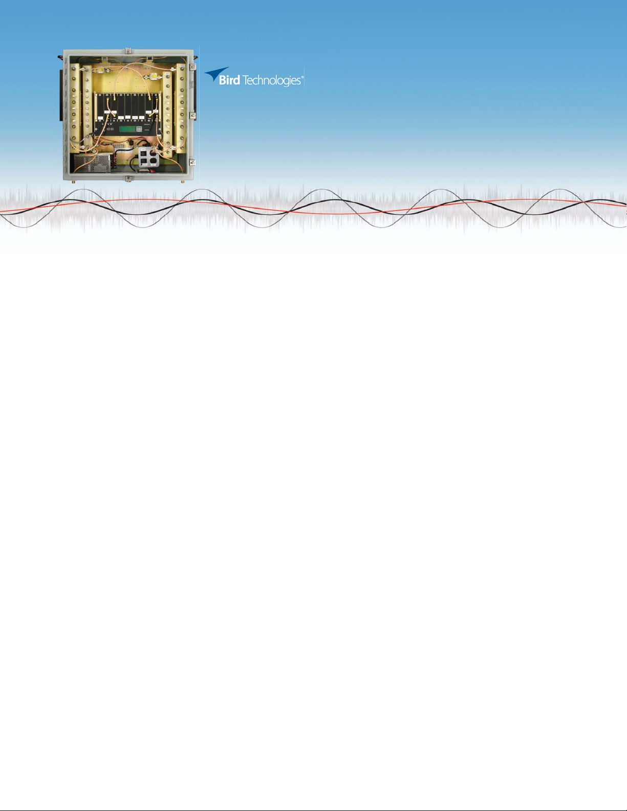
Signal Booster II
700, 800, 900 MHz Series
Mission Critical Reliability for In-building Coverage . . .
The Bird® Signal Booster II provides Public Safety grade reliability and coverage in disadvantaged RF locations for First Responders,
Public Safety/Governmental agencies and Private System Users. Reliable RF coverage is gained in basements, parking garages,
correctional facilities, courthouses, hospitals, malls and schools. Other challenging environments covered by the Signal
Booster II product include subways and rapid transit systems, airports, stadiums/arenas, high-rise buildings and large private
enterprise facilities and campuses.
Whether you are on the front line and depend on a reliable communication system or you are the systems integrator responsible
for implementing a dependable system, this new compact design facilitates installation and system optimization for rock
solid operation via a simple man-machine interface. Imbedded features for ease of initial setup include decoupled test
points for signal level detection, menu driven gain setting, front panel LED monitors for amplifier and power status, and an
at-a-glance LED bar graph to indicate relative level of Output Level Control (OLC). Additionally, this product offers a unique
on-board OLC DataLog feature that archives a User Signal Prole to facilitate optimum system conguration and performance.
Output Level Control (OLC) Circuit Monitors and Controls RF Output
Power
} Maintains maximum required output power while preventing damage
and excessive emissions per FCC requirements
} Easy-to-read LED bar graph
} Unique OLC DataLog feature facilitates system maintenance and optimization
Decoupled RF Test Points For Simplied Service
} Allow fast system measurements in both uplink and downlink directions
} Monitor signals for performance optimization
} Integrated design facilitates non-intrusive measurements
Secure, Non-Vented NEMA Enclosure Suitable for Extreme Indoor
and Outdoor Environments
Simple setup is achieved Via an Integral, Intuitive Web Browser
User Interface
} No Tools Required
Optional Features Available
} Comm Card II for remote communications and control
} Fiber optic link interface*
} Redundant PA conguration*
} -48 VDC input*
} Automatic Voice / Pager Dialer
DC Backup Interface Accepts +24 to +27 VDC and optional -48 VDC
*Contact Factory for these models
Microprocessor Controlled Fault Monitoring and Alarming
Ensures Reliable Operation and Flexible Conguration
} Control system continuously monitors parameters including voltage,
current, temperature and OLC activity
} LEDs on each module quickly annunciate source of fault
} Simple, back-lit liquid crystal display (LCD) and switch control
} Fault triggers annunciation on panel, alarm contact closure and
internal recording of failed subsystem
Card Cage Modularity
} Easy “slide-in” replacement process
} Facilitates ease of service and system conguration
High Performance Bandpass Filters
} Congured to customer requirements and addresses many
specications requiring custom passbands
} Standard models available with a variety of passbands*
Programmable Gain Setting
} Ease of initial conguration via front panel
} When used in conjunction with OLC DataLog, simplies post
installation adjustments
Three Major Gain Ranges Available
} Low:+ 45 dB, Medium:+ 60 dB, High:+ 80 dB
Signal Booster II
700, 800, 900 MHz Series
SPECIFICATIONS
Frequency Range See chart below
Passbands See chart below
Minimum Gain (dB)*
(depending on model)
Gain Adjustment Programmable attenuation,
3rd Order Output
Intercept Point
Maximum Input Level 0 dBm
RF Sampler PA Output sampler ports
Operating Temperature Rang -30°C to +50° C
Nominal impedance 50 ohms, <1.5:1 VSWR
Input/Output connectors N female
RF Sampler Connectors BNC female
AC Power Input 100-240 VAC; 50-60 Hz
DC Input Voltage +24 to +27 VDC
Housing** Painted Steel NEMA 4: Stainless
Nominal size 24” x 24” x 8”
Net Weight < 85 lbs.
+45 dB
+60 dB
+80 dB
0-30 dB, 0.5 dB steps
+55 dBm minimum,
with no attenuation
-48 VDC optional
Steel NEMA 4X: 19 inch Rack Mount
Maximum Output Power
764-806 MHz
806-869 MHz
896-941 MHz
Noise Figure (without attenuations)
764-806 MHz
806-869 MHz
896-941 MHz
Propagation Delay
764-806 MHz
806-869 MHz
896-941 MHz
Unit Power Consumption (AC/DC)
764-806 MHz
806-869 MHz
896-941 MHz
FCC Certication****
764-806 MHz
806-869 MHz
896-941 MHz
Industry Canada Certication****
764-806 MHz
806-869 MHz
896-941 MHz
+33 dBm (single carrier)
+30 dBm (single carrier)
+35 dBm (single carrier)
6.5 dB max for Low Gain (In-Line) &
Medium Gain
3.5 dB max for High Gain (Head-End)
6.5 dB max for Low Gain (In-Line)
3.5 dB max for Medium Gain &
High Gain (Head-End)
6.5 dB max for Low Gain (In-Line) &
Medium Gain
3.5 dB max for High Gain (Head-End)
<0.5 μs
<1 μs
<1.5 μs
<150 VA
<100 VA
<150 VA
EZZ5PI618350
EZZ5PI031202
EZZ5PI618850
1940A-PI618350
1940A-PI031202
1940A-PI618850
700, 800, 900 MHz SERIES SIGNAL BOOSTER II MODEL MATRIX
Model Number Frequency Range Passbands
61-83B-50-X12-XX 764-806 MHz 12 MHz BW (764-776 MHz DL / 794-806 MHz UL)
61-89A-50-X03-XX 806-869 MHz NPSPAC 3 MHz BW (Customer dened)***
61-89A-50-X05-XX 806-869 MHz 5 MHz BW (Customer dened)
61-89A-50-X06-XX 806-869 MHz 6 MHz BW (Customer dened)
61-89A-50-X10-XX 806-869 MHz 10 MHz BW (Customer dened)
61-88-50-X05-XX 896-941 MHz 5 MHz BW (896-901/ 935-940 MHz)
61-88-50-X06-XX 896-941 MHz 6 MHz BW (896-901/ 935-940 MHz)
* X = Gain A=80 dB, B=60 dB, C=45 dB
** XX = Housing Options G1: Painted Steel NEMA 4, G2: Stainless Steel NEMA 4X, RM: 19 inch Rack Mount (Frequencies MUST be provided with order).
Model Number Example 61-83B-50-A12-G1
*** NPSPAC downlink lter provides >38 dB of rejection ±1 MHz from the passband edge (either side).
**** Class B Type Booster. Type Acceptance under FCC Rules Part 90 and Industry Canada Certication Part RSS-131.
Please Contact Factory 716.549.4700 for non-standard congurations with custom frequency, windows and bandwidth.
30303 Aurora Rd. Solon, OH 44139 866.695.4569 www.bird-technologies.com
SignalBooster_SBIISeries-04072014
 Loading...