

Page 1
YOU'RE HEARD, LOUD AND CLEAR.
Installation and Operation Manual for
Automatic Voice/Pager Dialer Option
Model Number 6150-Page
Manual Part Number
7-9419-1
8625 Industrial Parkway, Angola, NY 14006 Tel: 716-549-4700 Fax: 716-549-4772 sales@birdrf.com www.bird-technologies.com
Page 2

Manual Part Number 7-9419
Copyright © 2006 TX RX Systems, Inc.
First Printing: May 2006
Version Number Version Date
1 05/19/06
Page 3
Warranty
This warranty applies for one year from shipping date.
TX RX Systems Inc. warrants its products to be free from defect in material and workman-
ship at the time of shipment. Our obligation under warranty is limited to replacement or
repair, at our option, of any such products that shall have been defective at the time of
manufacture.
TX RX Systems Inc. reserves the right to replace with merchandise of equal performance
although not identical in every way to that originally sold.
TX RX Systems Inc. is not liable for damage caused by lightning or other natural disasters.
No product will be accepted for repair or replacement without our prior written approval.
The purchaser must prepay all shipping charges on returned products. TX RX Systems
Inc. shall in no event be liable for consequential damages, installation costs or expense of
any nature resulting from the purchase or use of products, whether or not they are used in
accordance with instructions. This warranty is in lieu of all other warranties, either expressed or implied, including any implied warranty or merchantability of fitness. No representative is authorized to assume for TX RX Systems Inc. any other liability or warranty
than set forth above in connection with our products or services.
Terms and Conditions of Sale
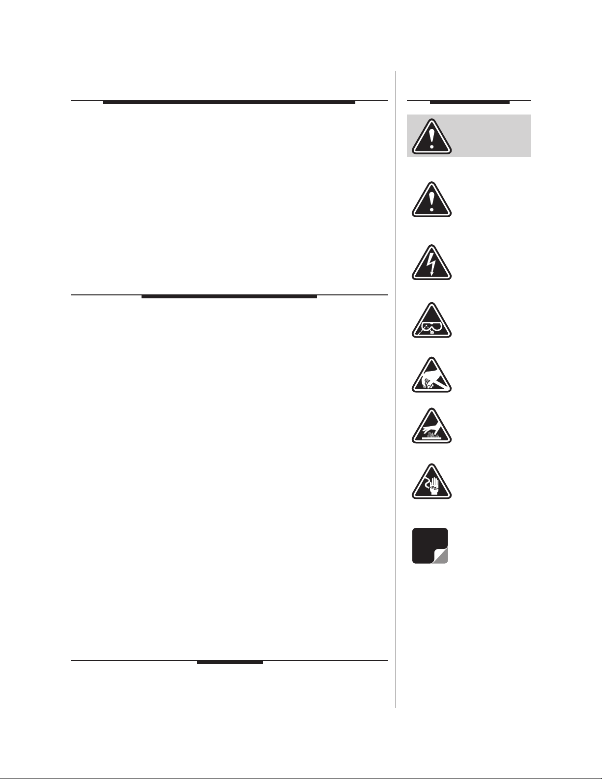
Symbols
Commonly Used
WARNING
CAUTION or
ATTENTION
High Voltage
PRICES AND TERMS: Prices are FOB seller’s plant in Angola, NY domestic packaging
only, and are subject to change without notice. Federal, State and local sales or excise
taxes are not included in prices. When Net 30 terms are applicable, payment is due
within 30 days of invoice date. All orders are subject to a $100.00 net minimum.
QUOTATIONS: Only written quotations are valid.
ACCEPTANCE OF ORDERS: Acceptance of orders is valid only when so acknowledged
in writing by the seller.
SHIPPING: Unless otherwise agreed at the time the order is placed, seller reserves the
right to make partial shipments for which payment shall be made in accordance with
seller’s stated terms. Shipments are made with transportation charges collect unless
otherwise specified by the buyer. Seller’s best judgement will be used in routing, except
that buyer’s routing is used where practicable. The seller is not responsible for selection
of most economical or timeliest routing.
CLAIMS: All claims for damage or loss in transit must be made promptly by the buyer
against the carrier. All claims for shortages must be made within 30 days after date of
shipment of material from the seller’s plant.
SPECIFICATION CHANGES OR MODIFICATIONS: All designs and specifications of
seller’s products are subject to change without notice provided the changes or modifications do not affect performance.
RETURN MATERIAL: Product or material may be returned for credit only after written
authorization from the seller, as to which seller shall have sole discretion. In the event
of such authorization, credit given shall not exceed 80 percent of the original purchase.
In no case will Seller authorize return of material more than 90 days after shipment from
Seller’s plant. Credit for returned material is issued by the Seller only to the original
purchaser.
ORDER CANCELLATION OR ALTERATION: Cancellation or alteration of acknowledged
orders by the buyer will be accepted only on terms that protect the seller against loss.
NON WARRANTY REPAIRS AND RETURN WORK: Consult seller’s plant for pricing.
Buyer must prepay all transportation charges to seller’s plant. Standard shipping policy
set forth above shall apply with respect to return shipment from TX RX Systems Inc. to
buyer.
NOTE
Use Safety
Glasses
ESD
Electrostatic
Discharge
Hot Surface
Electrical Shock
Hazard
Important
Information
Disclaimer
Product part numbering in photographs and drawings is accurate at time of printing.
Part number labels on TX RX products supercede part numbers given within this manual.
Information is subject to change without notice.
Page 4

GENERAL DESCRIPTION
Figure 1: Correct installation of the automatic voice/pager dialer model # 6150-Page.
The TX RX Systems automatic voice/pager dialer
model 6150-Page is an OEM product designed to
provide reliable emergency notification of an alarm
condition in the Signal Booster II. The automatic
dialer is installed inside the SB II cabinet and monitors the signal boosters alarm contacts.
When the booster indicates an alarm the voice/
pager dialer detects the condition and will initiate
notification calls to as many as 8 standard telephones, cellular phones, voice and/or numeric pagers. When activated, the dialer instantly begins
calling the notification numbers in sequence. The
notification messages are delivered 1 to 3 times in
a row in accordance with a pre-selected number of
dialing attempts.
The voice/pager dialer is programmable via a keypad located on the front of the unit behind a slideaway panel. Interface to the SB II is through the
boosters dry-contact alarm terminal screws. An
OEM operating manual is included with the automatic dialer which covers programming of the unit
in detail. The OEM operating manual should be
consulted prior to use. The automatic voice/pager
dialer can be factory installed at the time the SB II
is ordered or it can be installed in the field as an
option.
FIELD INSTALLATION
The voice/pager dialer should be mounted to the
inside front door of the SB II cabinet as shown in
Figure 1. All work should be performed by a qualified electronics technician familiar with the signal
booster system. Follow the step-by-step instructions listed below to complete the installation.
1) Loosen the clamps and open the SB II door.
Use the mounting dimensions shown in Figure
2 when laying out the position of the dialer on
the door of the signal booster. Mark the position
of four mounting holes on the door of the
booster cabinet as shown in the drawing. Placing the dialer in the correct position on the door
is important to avoid unnecessary interference
with subassemblies inside the cabinet. Also
note that the interconnect cables for the dialer
are a fixed length and need to extend from the
TXRX Systems Inc. Manual 7-9419-1 05/19/06 Page 1
Page 5

C
L
.136 DIA. THRU
4 - PLACES
REQUIRED DRILLING LAYOUT FOR
MOUNTING AUTO DIALER TO SIGNAL BOOSTER
ENCLOSURE DOOR (INSIDE)
BOTTOM OF DOOR
-A- DIM (See Chart)
1.5001.500
2.250 2.250
700 MHz
800 MHz
900 MHz
8.75"
8.75"
8.75"
SBII MODEL -A- DIM
Figure 2: Template for installing the mounting plate to the cabinet door.
1
+
-
-
+
12VDC
AUX
OUT
1 C C2 4 CC3
IN
OUT
Red to +
Black to -
Red to 1
White to C
Black to 2
Green to C
Back View of Auto Dialer Without Mounting Assembly
Board Assembly in
Card Cage Sub-Assy
DC Cable Assy
4-Conductor Cable
Remove lower pre-etched
tab of back cover plate
Wires to
12VDC
Wires to
Channels 1 & 2
Channels
Tel
Figure 3: Connecting cables to the rear of the dialer unit.
TXRX Systems Inc. Manual 7-9419-1 05/19/06 Page 2
Page 6

rear of the dialer to the alarm terminal screws
Figure 4: Hold down brackets for the dialer unit.
Attach brackets with 4-40 x 3/16”
phillips head screws
R11
R12
Enter
24v 12v UL PA
Cancel
DL PA
DOWNLINK OLC
UPLINK OLC
SYSTEMS
INC.
DC CABLE ASS'Y.
FROM AUTO DIALER
CARD CAGE SUB-ASS'Y.
IN SIGNAL BOOSTER
PATH
FOR DC
CABLE
Pin #1
Black Wire
Figure 5: Connecting the DC cable to the card cage.
and the card cage within the booster cabinet.
3) Attach the mounting plate to the inside of the
door with four Phillips screws (4-40 x 3/16”).
2) Drill out four 0.136 inch diameter holes at the
positions you marked on the cabinet door.
4) Remove the cover plate from the rear of the
dialer unit to expose the terminal screws. Connect the wires from the 4 conductor cable to the
TXRX Systems Inc. Manual 7-9419-1 05/19/06 Page 3
Page 7

channel 1 and 2 terminal screws as shown in
NOTE
Figure 6: Disconnecting the display user interface assembly from the card cage.
Disconnect
ribbon cable
here
Figure 3.
5) Connect the wires from the DC cable to the 12
VDC “+” and “-” terminal screws at the rear of
the dialer unit. Attach the red wire to the “+” terminal and the black wire to the “-” terminal as
shown in figure 3.
cage and the 4 conductor cable is brought to
the alarm terminal screws.
8) Plug the DC cable into the connector inside of
the card cage as shown in Figure 5. In order to
gain access to the inside of the card cage the
display user interface assembly must be temporarily removed.
6) Remove the lower pre-etched tab on the back
of the cover plate so that the DC and 4 conductor cable exit the rear of the dialer without being
Power to the SB II cabinet must be
turned OFF during the removal of
the display user interface.
pinched. Attach the dialer unit to the mounting
plate using two hold down brackets as shown in
Figure 4.
A) Loosen the two thumb-nuts which hold the dis-
play user interface assembly to the card cage.
7) Attach the two cables from the dialer unit to the
door using self-stick wire clamps as shown in
figure 1. Make sure there is enough slack in the
cables so they do not pinch or stretch when the
door is opened and closed. Route the cables
through the SB II cabinet such that the DC
B) Gently tilt only the top of the assembly up from
the card cage. Keep the bottom of the assembly
in place. The bottom mounting plate (part of the
card cage) has an overhang on it to support the
display user interface board. If the assembly is
cable can enter the lower left corner of the card
TXRX Systems Inc. Manual 7-9419-1 05/19/06 Page 4
Page 8

lifted straight out the overhang could possibly
Figure 7: Connecting the 4 conductor cable to the SB II alarm terminal screws.
Batt. COM
Batt. NC
Batt. NO
Alarm NC
Alarm NO
Alarm COM
6-POSITION
TERMINAL
EXISTING WIRES
IN SIGNAL
4-CONDUCTOR
FROM AUTO DIALER
Red to Batt NO
White to Batt COM
Black to Alarm NO
Green to Alarm COM
damage the interface circuit board.
F) Replace the display user interface assembly by
following steps D through A in reverse order.
C) With the display user interface assembly stand-
ing up straight gently move it upwards while lifting it out an inch or two. This should allow the
overhang to clear the interface circuit board
without damage.
D) Remove the ribbon cable that connects the dis-
play user interface assembly to the card cage.
Refer to Figure 6.
E) With the display user interface assembly tem-
porarily moved out of the way, route the DC
cable from the dialer through the inside of the
card cage along the path shown by the dotted
line in figure 5.
9) Connect the four conductor cable from the
dialer to the alarm terminal screws inside of the
booster cabinet as shown in Figure 7.
10) Connect a telephone line to the “TEL IN” con-
nector on the top of the dialer unit. See figure
4.
11) This completes the installation of the automatic
voice/pager dialer. The unit must be programmed for proper operation. Refer to the
OEM operating manual for programming specifics.
TXRX Systems Inc. Manual 7-9419-1 05/19/06 Page 5
Page 9

NOTES
TXRX Systems Inc. Manual 7-9419-1 05/19/06 Page 6
Page 10

Celsius to Fahrenheit Conversion Table
CELCIUS FAHRENHEIT
105 221.0
104 219.2
103 217.4
102 215.6
101 213.8
100 212.0
99 210.2
98 208.4
97 206.6
96 204.8
95 203.0
94 201.2
93 199.4
92 197.6
91 195.8
90 194.0
89 192.2
88 190.4
87 188.6
86 186.8
85 185.0
84 183.2
83 181.4
82 179.6
81 177.8
80 176.0
79 174.2
78 172.4
77 170.6
76 168.8
75 167.0
74 165.2
73 163.4
72 161.6
71 159.8
70 158.0
69 156.2
68 154.4
67 152.6
CELCIUS FAHRENHEIT
66 150.8
65 149.0
64 147.2
63 145.4
62 143.6
61 141.8
60 140.0
59 138.2
58 136.4
57 134.6
56 132.8
55 131.0
54 129.2
53 127.4
52 125.6
51 123.8
50 122.0
49 120.2
48 118.4
47 116.6
46 114.8
45 113.0
44 111.2
43 109.4
42 107.6
41 105.8
40 104.0
39 102.2
38 100.4
37 98.6
36 96.8
35 95.0
34 93.2
33 91.4
32 89.6
31 87.8
30 86.0
29 84.2
28 82.4
CELCIUS FAHRENHEIT
27 80.6
26 78.8
25 77.0
24 75.2
23 73.4
22 71.6
21 69.8
20 68.0
19 66.2
18 64.4
17 62.6
16 60.8
15 59.0
14 57.2
13 55.4
12 53.6
11 51.8
10 50.0
9 48.2
8 46.4
7 44.6
6 42.8
5 41.0
4 39.2
3 37.4
2 35.6
1 33.8
0 32.0
-1 30.2
-2 28.4
-3 26.6
-4 24.8
-5 23.0
-6 21.2
-7 19.4
-8 17.6
-9 15.8
-10 14.0
-11 12.2
CELCIUS FAHRENHEIT
-12 10.4
-13 8.6
-14 6.8
-15 5.0
-16 3.2
-17 1.4
-18 -0.4
-19 -2.2
-20 -4.0
-21 -5.8
-22 -7.6
-23 -9.4
-24 -11.2
-25 -13.0
-26 -14.8
-27 -16.6
-28 -18.4
-29 -20.2
-30 -22.0
-31 -23.8
-32 -25.6
-33 -27.4
-34 -29.2
-35 -31.0
-36 -32.8
-37 -34.6
-38 -36.4
-39 -38.2
-40 -40.0
-41 -41.8
-42 -43.6
-43 -45.4
-44 -47.2
-45 -49.0
-46 -50.8
-47 -52.6
-48 -54.4
-49 -56.2
-50 -58.0
Bird Technologies Group TX RX Systems Inc.
Page 11

Return Loss vs. VSWR
Watts to dBm
Return Loss VSWR
30 1.06
25 1.11
20 1.20
19 1.25
18 1.28
17 1.33
16 1.37
15 1.43
14 1.50
13 1.57
12 1.67
11 1.78
10 1.92
9 2.10
Watts dBm
300 54.8
250 54.0
200 53.0
150 51.8
100 50.0
75 48.8
50 47.0
25 44.0
20 43.0
15 41.8
10 40.0
5 37.0
4 36.0
3 34.8
2 33.0
1 30.0
dBm = 10log P/1mW
Where P = power (Watt)
Insertion Loss
Input Power (Watts)
50 75 100 125 150 200 250 300
3 25 38 50 63 75 100 125 150
2.5 28 42 56 70 84 112 141 169
2 32 47 63 79 95 126 158 189
1.5 35 53 71 88 106 142 177 212
1 40 60 79 99 119 159 199 238
Insertion Loss
.5 45 67 89 111 134 178 223 267
Output Power (Watts)
Free Space Loss
Distance (miles)
.25 .50 .75 1 2 5 10 15
150 68 74 78 80 86 94 100 104
220 71 77 81 83 89 97 103 107
460 78 84 87 90 96 104 110 113
860 83 89 93 95 101 109 115 119
940 84 90 94 96 102 110 116 120
Frequency (MHz)
1920 90 96 100 102 108 116 122 126
Free Space Loss (dB)
Free space loss = 36.6 + 20log D + 20log F
Where D = distance in miles and F = frequency in MHz
Bird Technologies Group TX RX Systems Inc.
Page 12

8625 Industrial Parkway, Angola, NY 14006 Tel: 716-549-4700 Fax: 716-549-4772 sales@birdrf.com www.bird-technologies.com
 Loading...