

Page 1

Wideband Power Sensor
Models 5012D, 5016D,
5017D, 5018D and 5019D
OPERATING INSTRUCTIONS
©Copyright 2014 by Bird Electronic Corporation
Instruction Book Part Number 920-5012S Rev. J
Page 2

Safety Precautions
The following are general safety precautions that are not necessarily related to any specific part or procedure, and do not necessarily appear elsewhere in this publication. These precautions
must be thoroughly understood and apply to all phases of operation and maintenance.
WARNING
Keep Away From Live Circuits
Operating Personnel must at all times observe general safety
precautions. Do not replace components or make
adjustments to the inside of the test equipment with the
high voltage supply turned on. To avoid casualties, always
remove power.
WARNING
Shock Hazard
Do not attempt to remove the RF transmission line while
RF power is present.
WARNING
Do Not Service Or Adjust Alone
Under no circumstances should any person reach into an
enclosure for the purpose of service or adjustment of
equipment except in the presence of someone who is
capable of rendering aid.
i
Page 3

WARNING
Safety Earth Ground
An uniterruptible earth safety ground must be supplied from the
main power source to test instruments. Grounding one
conductor of a two conductor power cable is not sufficient
protection. Serious injury or death can occur if this grounding is
not properly supplied.
WARNING
Resuscitation
Personnel working with or near high voltages should be
familiar with modern methods of resuscitation.
Safety Symbols
WARNING
Warning notes call attention to a procedure, which if not
correctly performed, could result in personal injury.
CAUTION
Caution notes call attention to a procedure, which if not
correctly performed, could result in damage to the
instrument.
Note: Calls attention to supplemental information.
ii
Page 4

Warning Statements
The following safety warnings appear in the text where there
is danger to operating and maintenance personnel, and are
repeated here for emphasis.
WARNING
Never attempt to connect or disconnect RF equipment from
the transmission line while RF power is being applied.
Leaking RF energy is a potential health hazard.
On page 3.
WARNING
Do not interrupt the calibration.
On page 6
Caution Statements
The following equipment cautions appear in the text and are
repeated here for emphasis.
iii
Page 5

Safety Statements
USAGE
ANY USE OF THIS INSTRUMENT IN A MANNER NOT
SPECIFIED BY THE MANUFACTURER MAY IMPAIR
THE INSTRUMENT’S SAFETY PROTECTION.
USO
EL USO DE ESTE INSTRUMENTO DE MANERA
NO ESPECIFICADA POR EL FABRICANTE, PUEDE
ANULAR LA PROTECCIÓN DE SEGURIDAD DEL
INSTRUMENTO.
BENUTZUNG
WIRD DAS GERÄT AUF ANDERE WEISE
VERWENDET ALS VOM HERSTELLER
BESCHRIEBEN, KANN DIE GERÄTESICHERHEIT
BEEINTRÄCHTIGT WERDEN.
UTILISATION
TOUTE UTILISATION DE CET INSTRUMENT QUI
N’EST PAS EXPLICITEMENT PRÉVUE PAR LE
FABRICANT PEUT ENDOMMAGER LE DISPOSITIF
DE PROTECTION DE L’INSTRUMENT.
IMPIEGO
QUALORA QUESTO STRUMENTO VENISSE
UTILIZZATO IN MODO DIVERSO DA COME
SPECIFICATO DAL PRODUTTORE LA PROZIONE
DI SICUREZZA POTREBBE VENIRNE
COMPROMESSA.
iv
Page 6

SERVICE
SERVICING INSTRUCTIONS ARE FOR USE BY
SERVICE - TRAINED PERSONNEL ONLY. TO AVOID
DANGEROUS ELECTRIC SHOCK, DO NOT PERFORM
ANY SERVICING UNLESS QUALIFIED TO DO SO.
SERVICIO
LAS INSTRUCCIONES DE SERVICIO SON PARA
USO EXCLUSIVO DEL PERSONAL DE SERVICIO
CAPACITADO. PARA EVITAR EL PELIGRO DE
DESCARGAS ELÉCTRICAS, NO REALICE NINGÚN
SERVICIO A MENOS QUE ESTÉ CAPACITADO
PARA HACERIO.
WARTUNG
ANWEISUNGEN FÜR DIE WARTUNG DES
GERÄTES GELTEN NUR FÜR GESCHULTES
FACHPERSONAL. ZUR VERMEIDUNG
GEFÄHRLICHE, ELEKTRISCHE SCHOCKS, SIND
WARTUNGSARBEITEN AUSSCHLIEßLICH VON
QUALIFIZIERTEM SERVICEPERSONAL
DURCHZUFÜHREN.
ENTRENTIEN
L’EMPLOI DES INSTRUCTIONS D’ENTRETIEN
DOIT ÊTRE RÉSERVÉ AU PERSONNEL FORMÉ
AUX OPÉRATIONS D’ENTRETIEN. POUR
PRÉVENIR UN CHOC ÉLECTRIQUE DANGEREUX,
NE PAS EFFECTUER D’ENTRETIEN SI L’ON N’A
PAS ÉTÉ QUALIFIÉ POUR CE FAIRE.
v
Page 7

ASSISTENZA TECNICA
LE ISTRUZIONI RELATIVE ALL’ASSISTENZA
SONO PREVISTE ESCLUSIVAMENTE PER IL
PERSONALE OPPORTUNAMENTE ADDESTRATO.
PER EVITARE PERICOLOSE SCOSSE ELETTRICHE
NON EFFETTUARRE ALCUNA RIPARAZIONE A
MENO CHE QUALIFICATI A FARLA.
vi
Page 8

About This Manual
This manual covers the operating and maintenance instructions for the following models:
5012D 5016D 5017D
5018D 5019D
Changes to this Manual
We have made every effort to ensure this manual is accurate.
If you discover any errors, or if you have suggestions for
improving this manual, please send your comments to our
Solon, Ohio factory. This manual may be periodically updated.
When inquiring about updates to this manual refer to the part
number and revision on the title page.
Literature Contents
Chapter Layout
Introduction — Describes the features of the Wideband
Power Sensor and Element Types.
Installation — Describes how to connection and install the
Wideband Power Sensor into the system that is being monitored.
Operation — Describes how to run and maintain the Wide-
band Power Sensor.
Specifications - Describes the basic information, settings,
and ranges of the Wideband Power Sensor
vii
Page 9

Table of Contents
Safety Precautions . . . . . . . . . . . . . . . . . . . . . . . . . . . . i
Safety Symbols . . . . . . . . . . . . . . . . . . . . . . . . . . . . . . . . . . . ii
Warning Statements . . . . . . . . . . . . . . . . . . . . . . . . . . . . . . iii
Caution Statements . . . . . . . . . . . . . . . . . . . . . . . . . . . . . . . iii
Safety Statements . . . . . . . . . . . . . . . . . . . . . . . . . . . . . . . . iv
About This Manual . . . . . . . . . . . . . . . . . . . . . . . . . . . vii
Changes to this Manual . . . . . . . . . . . . . . . . . . . . . . . . . . . vii
Literature Contents . . . . . . . . . . . . . . . . . . . . . . . . . . . . . . vii
Chapter Layout . . . . . . . . . . . . . . . . . . . . . . . . . . . . . . vii
Chapter 1 Introduction . . . . . . . . . . . . . . . . . . . . . . . . 1
Description . . . . . . . . . . . . . . . . . . . . . . . . . . . . . . . . . . . . . . 1
Chapter 2 Installation . . . . . . . . . . . . . . . . . . . . . . . . . 3
Connections . . . . . . . . . . . . . . . . . . . . . . . . . . . . . . . . . . . . . 3
Chapter 3 Operation . . . . . . . . . . . . . . . . . . . . . . . . . . 5
Zeroing Sensor . . . . . . . . . . . . . . . . . . . . . . . . . . . . . . . . . . . 5
5000-EX . . . . . . . . . . . . . . . . . . . . . . . . . . . . . . . . . . . . . 5
5000-XT . . . . . . . . . . . . . . . . . . . . . . . . . . . . . . . . . . . . . 6
Function Descriptions . . . . . . . . . . . . . . . . . . . . . . . . . . . . . 7
Average Power . . . . . . . . . . . . . . . . . . . . . . . . . . . . . . . . 7
VSWR . . . . . . . . . . . . . . . . . . . . . . . . . . . . . . . . . . . . . . . 8
Rho . . . . . . . . . . . . . . . . . . . . . . . . . . . . . . . . . . . . . . . . 8
VSWR . . . . . . . . . . . . . . . . . . . . . . . . . . . . . . . . . . . . . . 8
Return Loss (dB) . . . . . . . . . . . . . . . . . . . . . . . . . . . . . 8
viii
Page 10

Video Filter . . . . . . . . . . . . . . . . . . . . . . . . . . . . . . . . . . . 9
Peak Envelope Power . . . . . . . . . . . . . . . . . . . . . . . . . 10
Burst Average Power . . . . . . . . . . . . . . . . . . . . . . . . . . 11
Crest Factor . . . . . . . . . . . . . . . . . . . . . . . . . . . . . . . . . 12
Complementary Cumulative
Distribution Function (CCDF) . . . . . . . . . . . . . . . . . . . 13
Low Repetition Rate Waveforms . . . . . . . . . . . . . . . . 14
Chapter 4 Specifcations . . . . . . . . . . . . . . . . . . . . . . 17
5012D Specifications . . . . . . . . . . . . . . . . . . . . . . . . . . . . . 17
Sensor Characteristics . . . . . . . . . . . . . . . . . . . . . . . . . 17
Average Power . . . . . . . . . . . . . . . . . . . . . . . . . . . . . . . 18
Match Measurement . . . . . . . . . . . . . . . . . . . . . . . . . 18
Peak Envelope Power . . . . . . . . . . . . . . . . . . . . . . . . . 19
Burst Average Power . . . . . . . . . . . . . . . . . . . . . . . . . . 19
Crest Factor . . . . . . . . . . . . . . . . . . . . . . . . . . . . . . . . . 20
Complementary Cumulative
Distribution Function (CCDF) . . . . . . . . . . . . . . . . . . . 20
Physical and Environmental Specifications . . . . . . . . 20
5016D Specifications . . . . . . . . . . . . . . . . . . . . . . . . . . . . . 23
Sensor Characteristics . . . . . . . . . . . . . . . . . . . . . . . . . 23
Average Power . . . . . . . . . . . . . . . . . . . . . . . . . . . . . . . 24
Match Measurement . . . . . . . . . . . . . . . . . . . . . . . . . 24
Peak Envelope Power . . . . . . . . . . . . . . . . . . . . . . . . . 25
Burst Average Power . . . . . . . . . . . . . . . . . . . . . . . . . . 26
Crest Factor . . . . . . . . . . . . . . . . . . . . . . . . . . . . . . . . . 26
Complementary Cumulative
Distribution Function (CCDF) . . . . . . . . . . . . . . . . . . . 26
Physical and Environmental Specifications . . . . . . . . 27
5017D Specifications . . . . . . . . . . . . . . . . . . . . . . . . . . . . . 29
Sensor Characteristics . . . . . . . . . . . . . . . . . . . . . . . . . 29
ix
Page 11

Average Power . . . . . . . . . . . . . . . . . . . . . . . . . . . . . . . 30
Match Measurement . . . . . . . . . . . . . . . . . . . . . . . . . 30
Peak Envelope Power . . . . . . . . . . . . . . . . . . . . . . . . . 31
Burst Average Power . . . . . . . . . . . . . . . . . . . . . . . . . . 32
Crest Factor . . . . . . . . . . . . . . . . . . . . . . . . . . . . . . . . . 32
Complementary Cumulative
Distribution Function (CCDF) . . . . . . . . . . . . . . . . . . . 32
Physical and Environmental Specifications . . . . . . . . 33
5018D Specifications . . . . . . . . . . . . . . . . . . . . . . . . . . . . . 35
Sensor Characteristics . . . . . . . . . . . . . . . . . . . . . . . . . 35
Average Power . . . . . . . . . . . . . . . . . . . . . . . . . . . . . . . 36
Match Measurement . . . . . . . . . . . . . . . . . . . . . . . . . 36
Peak Envelope Power . . . . . . . . . . . . . . . . . . . . . . . . . 37
Burst Average Power . . . . . . . . . . . . . . . . . . . . . . . . . . 38
Crest Factor . . . . . . . . . . . . . . . . . . . . . . . . . . . . . . . . . 38
Complementary Cumulative
Distribution Function (CCDF) . . . . . . . . . . . . . . . . . . . 39
Physical and Environmental Specifications . . . . . . . . 39
5019D Specifications . . . . . . . . . . . . . . . . . . . . . . . . . . . . . 41
Sensor Characteristics . . . . . . . . . . . . . . . . . . . . . . . . . 41
Average Power . . . . . . . . . . . . . . . . . . . . . . . . . . . . . . . 42
Match Measurement . . . . . . . . . . . . . . . . . . . . . . . . . 42
Peak Envelope Power . . . . . . . . . . . . . . . . . . . . . . . . . 43
Burst Average Power . . . . . . . . . . . . . . . . . . . . . . . . . . 44
Crest Factor . . . . . . . . . . . . . . . . . . . . . . . . . . . . . . . . . 44
Complementary Cumulative
Distribution Function (CCDF) . . . . . . . . . . . . . . . . . . . 44
Physical and Environmental Specifications . . . . . . . . 45
Limited Warranty . . . . . . . . . . . . . . . . . . . . . . . . . . . . 47
x
Page 12

xi
Page 13

Chapter 1 Introduction
Description
The Bird 5012D, 5016D, 5017D, 5018D, and 5019D Wideband
Power Sensor (WPS) is a Thruline sensor that can measure
average, peak, or burst power, VSWR, crest factor, and Complementary Cumulative Distribution Function (CCDF). It can be
used with the Bird 5000-EX and 5000-XT Digital Power Meters
(DPM), Site Analyzer, SignalHawk and the Bird Virtual Power
Meter Software (VPM).
Note: Firmware upgrades extending the WPS’s
capabilities may be periodically released. For the
latest firmware upgrade, contact Bird Customer
Service at (440) 248-1200 or visit our website at
http://www.bird-technologies.com
1
Page 14

2
Page 15
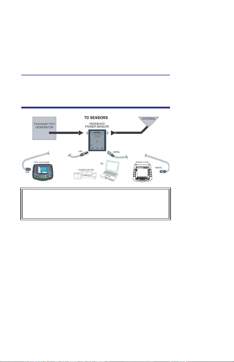
Chapter 2 Installation
Connections
Note: VPM1
5012D
5016D
5017D
5018D
5019D
ONLY for Serial
Connections.
5012A
USB Only
USB & Serial
Serial Only
WARNING
Never attempt to connect or disconnect RF equipment from
the transmission line while RF power is being applied.
Leaking RF energy is a potential health hazard.
To connect the WPS to the Digital Power Meter, use the serial
cable provided. Connect the male end of the cable to the DPM
and the female end to the WPS. A separate power supply for
the WPS is not required when using a DPM.
Note: Connect the WPS to the RF line so that the
arrow on the sensor points towards the load.
There are two ways to connect the WPS to a PC running the
Virtual Power Meter Software:
3
Page 16

FOR USE WITH OLDER VPM1 SOFTWARE ONLY: To
connect using the serial port, first connect a 12V DC
power supply to the WPS. Once the STATUS LED turns
on and begins blinking, use the serial cable provided
and connect the female end of the cable to the computer and the male end to the WPS. The WPS must be
powered up before connecting to the PC.
FOR USE WITH EITHER VPM1 OR VPM2 SOFTWARE:
To connect using the USB port, connect the USB cable
to the computer and to the WPS. A separate power
supply is not required when using the USB port.
Note: When using the optional serial to USB
adapter, connect the WPS serial port to the
adapter’s serial port, and the adapter’s USB
connector to the PC.
4
Page 17

Chapter 3 Operation
Zeroing Sensor
5000-EX
Over time, the sensor’s “zero value” (reading with no applied RF
power) can drift due to environmental factors (temperature,
humidity, etc.) This can make the readings performed by this sensor less accurate by the drift value. If the drift would be a significant
error, re zero the sensor.
1. Ensure the sensor has reached a stable operating temperature.
2. Ensure no RF power is applied to the sensor.
3. Press “Zero” to begin Calibration.
Note: Calibration will take about 40 seconds. Do
not interrupt the calibration! A bar on the screen
will display calibration progress.
4. Do one of the following:
If the calibration is successful, “Cal Pass” or “Calibra-
tion
Complete” will be displayed.
a. Press any key to return to normal operation.
5
Page 18

If calibration fails, “Cal Fail” will be displayed.
a. Press a key to return to normal operation,
b. Ensure that the WPS is properly connected, and the
RF is off.
c. Rezero. Go back to Step 3.
5000-XT
1. Make sure the sensor has reached a stable operating
temperature.
2. Make sure no RF power is applied to the sensor.
3. Press and hold “0” for two seconds to begin zero calibration.
WARNING
Do not interrupt the calibration.
Note: “Zero/Cal” will be displayed and calibration
will begin.
Note: Zeroing the sensor takes 60 seconds. The
bar graph will display calibration progress.
Note: When complete, “PASS” should be displayed.
4. Press Enter to return to normal operation when zeroing is
complete.
Note: If “FAIL” is displayed, make sure no RF power
is applied to the sensor and perform the procedure
again.
6
Page 19

Function Descriptions
Figure 1 Average and Peak Envelope Power -
Square Wave Signal
Average Power
Average power is a measure of the equivalent “heating”
power of a signal, as measured with a calorimeter. It measures the total RF power in the system, and does not depend
on number of carriers or modulation scheme. The WPS is a
broadband sensor that measures power across its entire frequency range. Its diodes operate in their ‘square law’ region
so that the detector output is directly proportional to the
average power, without any additional error correction.
Average power is the most important measurement of any
transmission system since the average power is normally specified on the operating license. It is also valuable as a maintenance tool, showing overall system health, and for calibration.
7
Page 20

VSWR
VSWR measures the relation between forward and reflected
average power. The Bird Wideband Power Sensor calculates
the VSWR from the Forward and Reflected Average Power
measurements. Rho and Return Loss are also the same measurement, but in different units:
Rho
Rho PRPF=
VSWR
VSWR
1 +
------------=
1 –
Return Loss (dB)
ReturnLoss dB10 PRPFlog=
The health of the feedline and antenna systems can be monitored using VSWR measurement under full power operating
conditions. High VSWR is an indicator of feed line damage,
overtightened cable or feed line clamps, or antenna changes/
damage due to weather conditions, icing, or structural damage to the tower.
8
Page 21

Video Filter
Figure 2 Video Filter Settings, 300 kHz Signal
Except for average power and VSWR measurements, all WPS
measurements rely on a variable video filter to improve accuracy. This filter can be set to either 4.5 kHz, 400 kHz, or full
bandwidth. It should be as narrow as possible while still being
larger than the demodulated signal bandwidth (video bandwidth). Narrowing the filter limits the noise contribution
caused by interfering signals. Listed below are some common
modulation schemes and the appropriate video filter.
Video Filter Modulation Type
4.5 kHz CW Burst (Burst width > 150 μs), Voice Band
AM, FM, Phase Modulation, Tetra
400 kHz CW Burst (b.w. > 3 μs), GSM, 50 kHz AM,
DQPSK
Full
Bandwidth
CW Burst (b.w. > 200 ns), CDMA, WCDMA,
DQPSK, DAB/DVB-T
9
Page 22

Peak Envelope Power
Peak power measurements detect amplitude changes as a signal modulates the carrier envelope. The WPS operates in an
asynchronous cycle: 300 ms of waveform sampling followed by
a 50 ms reset period. The peak power is then displayed and the
cycle repeats. The display therefore updates about three times
per second.
Transmitter overdrive can be detected with peak measurements. Common problems are overshoot at the beginning of
burst packets, amplitude modulation, and excessive transients. These damage system components with excessive peak
power and also cause data degradation, increasing the Bit
Error Rate. For TDMA applications, Peak and Burst Power
measurements are used to detect overshoot in single
timeslots. Other timeslots must be turned off for this test.
10
Page 23

Burst Average Power
Figure 3 Burst Average Power
Burst width (BW) is the duration of a pulse. Period (P) is the
time from the start of one pulse to the start of the next pulse.
Duty cycle (D) is the percentage of time that the transmitter is
on. To calculate the duty cycle simply divide the burst width by
the period (D = BW / P). Low duty cycles mean that the burst
width is much less than the period; a large amount of dead
time surrounds each burst. For low duty cycles, the burst average power will be much larger than the average power.
After peak power is measured, a threshold of ½ the peak is
set. The sampled power crosses that threshold at the beginning and end of each burst. The time between crossings is
used to calculate the duty cycle. Burst Average Power is calculated by dividing the Average Power by the Duty Cycle.
Burst power measurements provide accurate, stable measurements in bursting applications such as TDMA and radar.
Accurately measuring the output signal strength is essential
for optimizing radar coverage patterns. Actual transmitted
power in a single timeslot can be deter-mined in TDMA. The
other timeslots must be off during this test.
11
Page 24

Crest Factor
Figure 4 Crest Factor - 10 dB CDMA Signal - 100 W
Peak - 10 W Ave
Crest factor (CF) is the ratio of the peak and average powers, in
dB. The WPS calculates the Crest Factor from the Forward Peak
and Average Power measurements.
Crest factor is becoming one of the most important measurements as communication systems move into the digital age. For
CDMA and similar modulation types the CF may reach 10 dB. If
the crest factor is too large, the transmitter will not be able to
handle the peak powers and amplitude distortion will occur.
Crest factor can also detect overdrive and overshoot problems.
Knowing the CF allows end-users to more accurately set base
station power and lower operating costs.
12
Page 25

Complementary Cumulative Distribution Function (CCDF)
Figure 5 CCDF - 100 W Signal - 80 W Threshold -
20% CCDF
CCDF measures the amount of time the power is above a
threshold. Equivalently, it is the probability that any single
measurement will be above the threshold. The WPS samples
the power over a 300 ms window and compares it to a userspecified threshold, in Watts. The time above the threshold
relative to the total time is the CCDF.
CCDF measurements are most useful for pseudo-random signals, such as WCDMA, where a high CCDF means that the transmitter is being overdriven. CCDF can also detect amplitude
distortion within an envelope caused by unwanted modulating
signals. In TDMA systems, CCDF indicates the health of power
amplifier stages and their ability to sustain rated power over an
appropriate timeframe. As a trouble-shooting aid, CCDF allows
tracking of trends such as amplifier overdrive (which can cause
dropped calls and high bit error rates).
13
Page 26

Low Repetition Rate Waveforms
Many of today's channel access methods involve the use of
low repetition frequency time division-multiple access
(TDMA) techniques. Examples of these relatively new TDMA
formats include Digital Mobile Radio(DMR), and TETRA systems. The DMR format uses an approach where two discrete
time slots provide access to a single 25 kHz communication
channel, providing the equivalent of 12.S kHz channel bandwidth for the system. The modulation techniques used within
these systems vary, from relatively benign forms of frequency
shift keying, to more complex quadrature formats such as
Quadrature Phase Shift Keying (QPSK).When measuring the
power output of transmitters using the DMR format, the base
station transmitters will normally transmit with both time
slots active, even if there is no traffic on one of the time slots.
Under these conditions, it is a simple matter to measure the
average power of this continuous waveform. When measuring
the output power of subscriber units however, normal operation is to use only one time slot, approximately 30 ms in duration, followed by approximately 30 ms at zero power in the
interval where the other time slot would normally be located.
The remaining waveform resembles a 30 ms burst, occurring
at a 17 Hz repetition rate. Since the measurement of average
power under this condition would result in an unstable reading, the correct measurement would be that of burst average
power. When making this measurement, the sensor will measure the duty cycle of the signal, as well as the average power,
and compute the burst average power of the waveform based
upon these parameters.
14
Page 27

Figure 6 Low Rep Waveform
15
Page 28

16
Page 29

Chapter 4 Specifcations
5012D Specifications
Sensor Characteristics
Frequency Range 350 MHz to 4 GHz
RF Power Range 0.15 W to 150 W average, 4W to 400
W peak
Maximum Power See Figure 8 on page 19.
Impedance, Nominal 50 ohms
Insertion Loss, Max:
0.35 – 1 GHz
1 – 4 GHz
Input VSWR, Max:
0.35 – 2.5 GHz
2.5 – 4 GHz
Directivity, Min:
0.35 – 3 GHz
3 – 4 GHz
RF Connectors N Female
Interface:
DPM
PC Serial Port
PC USB Port
0.05 dB
0.1 dB
1.05
1.10
30 dB
28 dB
Male DB-9, EIA-232, 9600 Baud, no
parity, 8 data bits, 1 stop bit
Female DB-9, EIA-232, 9600 Baud,
no parity, 8 data bits, 1 stop bit
USB 1.1 interface
17
Page 30

Power Supply:
DPM
USB Port
DC Connector
From host instrument via cable
Less than one low-power USB load
7 – 18 Vdc, < 100 mA
Data Logging In VPM Software
Average Power
RF Power Range 0.15 – 150 W
Peak/Average Ratio, Max 12 dB
Measurement Uncert. ± (4% of reading ± 0.05 W)
a. Above 35 °C or below 15 °C add 3%
Match Measurement
a
Measurement Range:
Return Loss
)
Rho (
VSWR
0 to 23 dB
0.07 to 0.999
1.15 to 99.9
Forward Power, Min .5 W
Measurement Uncert. See Figure 7 on page 18.
Figure 7 Match Measure Uncertainty
4
2
0
-2
Uncertainty(dB)
-4
-6
Return Loss
Above
3GHz+
Above
-25 -20 -15 -10 -5 0
3GHzBelow
3GHz+
18
4
2
0
-5 0
-2
Uncertainty(dB)
-4
-6
Page 31

Peak Envelope Power
RF Power Range 4.0 – 400 W
Measurement Uncert.:
burst width > 200 μs
1 μs < b.w
. < 200 μs
burst width < 1 μs
burst width < 0.5 μs
± (7% of reading + 0.2 W)
± (10% of reading + 0.4 W)
± (15% of reading + 0.4 W)
± (20% of reading + 0.4 W)
a
b
Minimum Pulse Width: 400 ns
a. Max. power depends on frequency and system VSWR.
See Figure 8 on page 19.
b. Above 35 °C or below 15 °C add 3%
For D < 0.1 add 0.1 W
For period > 0.1s add (1.5% + 0.15 W)
Figure 8 Max. Peak Power
10000
1000
Power (Watts)
100
0.1 1 10
Frequency (GHz)
VSWR=1
VSWR=1.5
VSWR=3
Burst Average Power
Power Range 2 W to 150 W average
Burst Width 1 μs – 5 ms
Repetition Rate, Min 5 Hz (with 12 dB peak / average ratio)
Duty Cycle (D)** 0.02 to 1 (D = Burst Width / Period)
b
b
b
19
Page 32

Measurement Uncert. ± (6% of reading + 50/D mW)
a. Above 35 °C or below 15 °C add 3%
** Duty Cycle and CCDF read out dependent on display
method.
a
Crest Factor
RF Power Range 0.15 to 150 W average, 4 W
minimum peak
Measurement Uncert. Linear sum of peak and average
power uncertainty
Complementary Cumulative Distribution Function (CCDF)
Measurement Range* 0.1 to 100%
Measurement Uncert. ± 2%
Threshold Level Range 2 to 400 W peak
Level Set Accuracy As peak power uncert. + 2%
* Duty Cycle and CCDF read out dependent on display
method.
Physical and Environmental Specifications
Temp, Operating –10 to +50 °C (+14 to +122 °F)
Temp, Storage –40 to +80 °C (–40 to +176 °F)
Mechanical Shock
ibration
and V
Humidity, Max 95% (non-condensing)
MIL-PRF-28800F class 3
20
Page 33

Altitude, Max 15,000 ft. (4,500 m)
Dimensions,
Nominal
Weight, Max 1.2 lb. (0.55 kg)
EMC EMC Directive (2004/108/EC)
4.75” x 4.6” x 1.3” (121 x 117 x 33 mm)
European Standard: EN 61326—
Electrical Equipment for measurement,
control and laboratory use; EMC
Requirements
Test Spec (for radiated immunity): EN
61000-4-3—Testing and measurement
techniques - 10V/meter
21
Page 34

22
Page 35

5016D Specifications
Sensor Characteristics
Frequency Range 350 MHz to 4 GHz
RF Power Range 25 mW – 25 W Average, 1W to 60 W
peak
Maximum Power See Figure 9 on page 24.
Impedance, Nominal 50 ohms
Insertion Loss, Max:
0.35 – 1 GHz
1 – 4 GHz
Input VSWR, Max:
0.35 – 2.5 GHz
2.5 – 4 GHz
Directivity, Min:
0.35 – 3 GHz
3 – 4 GHz
RF Connectors N Female
Interface:
DPM
PC Serial Port
PC USB Port
Power Supply:
DPM
USB Port
DC Connector
Data Logging In VPM software
0.05 dB
0.1 dB
1.05
1.10
30 dB
28 dB
Male DB-9, RS-232, 9600 Baud, no
, 8 data bits, 1 stop bit
parity
Female DB-9, EIA-232, 9600 Baud,
no parity
USB 1.1 interface
From host instrument via cable
less than one low-power USB load
7 – 18 Vdc, < 100 mA
, 8 data bits, 1 stop bit
23
Page 36

Average Power
RF Power Range 25 mW to 25 W
Peak/Average Ratio, Max 12 dB
Measurement Uncert. ± (4% of reading + 8 mW)
a. Above 35 °C or below 15 °C add 3%
Match Measurement
a
Measurement Range:
Return Loss
)
Rho (
VSWR
0 to 23 dB
007 to 0.999
1.15 to 99.9
Forward Power, Min 0.1 W
Measurement Uncert. See Figure 10 on page 25.
Figure 9 Match Measure Uncertainty
4
2
0
-2
Uncertainty(dB)
-4
-6
Return Loss
-25 -20 -15 -10 -5 0
24
Above
3GHz+
Above
3GHz-
Below
3GHz+
Page 37

Peak Envelope Power
RF Power Range 1.0 W – 60 W
Measurement Uncert.:
burst width > 200 μs
1 μs < b.w
. < 200 μs
burst width < 1 μs
burst width < 0.5 μs
± (7% of reading + 0.05 W)
± (10% of reading + 0.1 W)
± (15% of reading + 0.1 W)
± (20% of reading + 0.1 W)
a
Minimum Pulse Width: 400 ns
a. Max. power depends on frequency and system VSWR.
See Figure 10 on page 25.
b. Above 35 °C or below 15 °C add 3%
For D < 0.1 add 0.1 W
For period > 0.1s add (1.5% + 0.15 W)
Figure 10 Max. Peak Power
10000
1000
Power (Watts)
100
0.1 1 10
Freque ncy (GHz)
VSWR=1
VSWR=1.5
VSWR=3
b
b
b
b
25
Page 38

Burst Average Power
Power Range 1.0 W – 25 W average
Burst Width 1 μs – 5 ms
Repetition Rate, Min 5 Hz (with 12 dB peak/average ratio)
Duty Cycle (D)** 0.02 to 1 (D = Burst Width / Period)
Measurement Uncert. ± (6% of reading + 8/D W)
a. Above 35 °C or below 15 °C add 3%
** Duty Cycle and CCDF read out dependent on display
method.
a
Crest Factor
RF Power Range 25 mW to 25 W average
Measurement Uncert. Linear sum of peak and average
power uncertainty
Complementary Cumulative Distribution Function (CCDF)
Measurement Range* 0.1 – 100%
Measurement Uncert. ± 2%
Threshold Level Range 25 mW to 60 W
Level Set Accuracy As peak power uncert. + 2%
* Duty Cycle and CCDF read out dependent on display
method.
26
Page 39

Physical and Environmental Specifications
Temp, Operating –10 to +50 °C (+14 to +122 °F)
Temp, Storage –40 to +80 °C (–40 to +176 °F)
Mechanical Shock
ibration
and V
Humidity, Max 95% (non-condensing)
Altitude, Max 15,000 ft. (4,500 m)
Dimensions, Nominal 4.75” x 4.6” x 1.3” (121 x 117 x 33
Weight, Max 1.2 lb. (0.55 kg)
EMC EMC Directive (2004/108/EC)
MIL-PRF-28800F class 3
mm)
European Standard: EN 61326—
Electrical Equipment for measurement,
control and laboratory use; EMC
Requirements
Test Spec (for radiated immunity): EN
61000-4-3—T
techniques - 10V/meter
esting and measurement
27
Page 40

28
Page 41

5017D Specifications
Sensor Characteristics
Frequency Range 25 MHz to 1 GHz
RF Power Range 500 mW to 500 W average, 13.3W to
1300 W peak
Maximum Power See Figure 10 on page 25.
Impedance, Nominal 50 ohms
Insertion Loss, Max:
25 – 50 MHz
Input VSWR, Max:
25 – 1000 MHz 1.05
Directivity, Min:
25 – 50 MHz
51 – 1000 MHz
RF Connectors N Female
Interface:
DPM
PC Serial Port
PC USB Port
Power Supply:
DPM
USB Port
DC Connector
Data Logging In VPM software
0.05 dB
29 dB
30 dB
Male DB-9, RS-232, 9600 Baud, no
, 8 data bits, 1 stop bit
parity
Female DB-9, EIA-232, 9600 Baud,
no parity
USB 1.1 interface
From host instrument via cable
less than one low-power USB load
7 – 18 Vdc, < 100 mA
, 8 data bits, 1 stop bit
29
Page 42

Average Power
RF Power Range 500 mW – 500 W
Peak/Average Ratio, Max 12 dB
Measurement Uncert. ± (4% of reading + 166 mW)
a. Above 35 °C or below 15 °C add 3%
Match Measurement
a
Measurement Range:
Return Loss
)
Rho (
VSWR
0 to 23 dB
0.07 to 1.0
1.15 to 99.9
Forward Power, Min 0.05 W
Measurement Uncert. See Figure 11 on page 30.
Figure 11 Match Measure Uncertainty
4
2
0
-2
Uncertainty(dB)
-4
-6
Return Loss
30
-25 -20 -15 -10 -5 0
Page 43

Peak Envelope Power
RF Power Range 13.3 – 1300 W
Measurement Uncert.:
burst width > 200 μs
1 μs < b.w
. < 200 μs
burst width < 1 μs
burst width < 0.5 μs
± (7% of reading + 0.7 W)
± (10% of reading + 1.4 W)
± (15% of reading + 1.4 W)
± (20% of reading + 1.4 W)
a
Minimum Pulse Width: 400 ns
a. Max. power depends on frequency and system VSWR.
See Figure 12 on page 31.
b. Above 35 °C or below 15 °C add 3%
For D < 0.1 add 0.1 W
For period > 0.1s add (1.5% + 0.15 W)
Figure 12 Max. Peak Power
10000
1000
Power (Watts)
100
0.1 1 10
Freque ncy (GHz)
VSWR=1
VSWR=1.5
VSWR=3
b
b
b
b
31
Page 44

Burst Average Power
Power Range 13 – 500 W average
Burst Width 1 μs – 5 ms
Repetition Rate, Min 5 Hz (with 12 dB Peak/Avg ratio)
Duty Cycle (D)** 0.02 to 1 (D = Burst Width / Period)
Measurement Uncert. ± (6% of reading + 166/D mW)
a. Above 35 °C or below 15 °C add 3%
** Duty Cycle and CCDF read out dependent on display
method.
a
Crest Factor
RF Power Range 500 mW to 500 W average, 13.3W
minimum peak
Measurement
Uncert.
Linear sum of peak and average power
uncertainty
Complementary Cumulative Distribution Function (CCDF)
Measurement Range* 0.1 – 100%
Measurement Uncert. ± 2%
Threshold Level Range 13.0 W to 1300 W peak
Level Set Accuracy As peak power uncert. + 2%
* Duty Cycle and CCDF read out dependent on display
method.
32
Page 45

Physical and Environmental Specifications
Temp, Operating –10 to +50 °C (+14 to +122 °F)
Temp, Storage –40 to +80 °C (–40 to +176 °F)
Mechanical Shock
ibration
and V
Humidity, Max 95% (non-condensing)
Altitude, Max 15,000 ft. (4,500 m)
Dimensions, Nominal 4.75” x 4.6” x 1.3” (121 x 117 x 33 mm)
Weight, Max 1.2 lb. (0.55 kg)
EMC EMC Directive (2004/108/EC)
MIL-PRF-28800F class 3
European Standard: EN 61326—
Electrical Equipment for
measurement, control and laboratory
use; EMC Requirements
Test Spec (for radiated immunity): EN
61000-4-3—T
measurement techniques - 10V/meter
esting and
33
Page 46

34
Page 47

5018D Specifications
Sensor Characteristics
Frequency Range 150 MHz to 4.0 GHz
RF Power Range 100 mW to 25 W average,
60 W peak
Maximum Power See Figure 10 on page 25.
Impedance, Nominal 50 ohms
Insertion Loss, Max:
150 – 1000 MHz
1000 – 4000 MHz
Input VSWR, Max:
150 – 2500 MHz
2500 – 4000 MHz
Directivity, Min:
150 – 3000 MHz
3000 – 4000 MHz
RF Connectors N Female
Interface:
DPM
PC Serial Port
PC USB Port
0.05 dB from 0.15 to 1.0 GHz
0.01 dB from 1.0 to 4 GHz
1.05 from 0.15 to 2.5 GHz
1.10 dB from 2.5 to 4 GHz
30 dB
28 dB
Male DB-9, RS-232, 9600 Baud, no
parity, 8 data bits, 1 stop bit
Female DB-9, EIA-232, 9600 Baud,
no parity, 8 data bits, 1 stop bit
USB 1.1 interface
35
Page 48

Power Supply:
DPM
USB Port
DC Connector
Data Logging In VPM software
From host instrument via cable
less than one low-power USB load
7 – 18 Vdc, < 100 mA
Average Power
RF Power Range 25 mW – 25 W
Peak/Average Ratio, Max 12 dB
Measurement Uncert. ± (4% of reading + 0.008 mW)
a. Above 35 °C or below 15 °C add 3%
Match Measurement
a
Measurement Range:
Return Loss
)
Rho (
VSWR
Forward Power, Min 0.1 W
Measurement Uncert. See Figure 11 on page 30.
0 to 23 dB
0.07 to 1.0
1.15 to 99.9
36
Page 49

Figure 13 Match Measure Uncertainty
4
2
0
-2
Uncertainty(dB)
-4
-6
Return Loss
Peak Envelope Power
RF Power Range 4 – 60 W
Measurement Uncert.:
burst width > 200 μs
1 μs < b.w
. < 200 μs
burst width < 1 μs
burst width < 0.5 μs
± (7% of reading + 0.05 W)
± (10% of reading + 0.1 W)
± (15% of reading + 0.1 W)
± (20% of reading + 0.1 W)
Minimum Pulse Width: 400 ns
a. Max. power depends on frequency and system VSWR.
See Figure 12 on page 31.
b. Above 35 °C or below 15 °C add 3%
For D < 0.1 add 0.1 W
For period > 0.1s add (1.5% + 0.15 W)
a
-25 -20 -15 -10 -5 0
b
b
b
b
37
Page 50

Figure 14 Max. Peak Power
q
)
10000
1000
Power (Watts)
100
0.1 1 10
Fre
uency (GHz
VSWR=1
VSWR=1.5
VSWR=3
Burst Average Power
Power Range 25 mW – 25 W average
Burst Width 1 μs – 5 ms
Repetition Rate, Min 5 Hz (with 12 dB Peak/Avg ratio)
Duty Cycle (D)** 0.02 to 1 (D = Burst Width / Period)
Measurement Uncert. ± (6% of reading + 0.008/D W)
a
a. Above 35 °C or below 15 °C add 3%
** Duty Cycle and CCDF read out dependent on display
method.
Crest Factor
RF Power Range 25 mW to 25 W
Measurement Uncert. ± (6% of reading +0.008/D W)
a. Above 35 °C or below 15 °C add 3%
38
a
Page 51

Complementary Cumulative Distribution Function (CCDF)
Measurement Range* 0.1 – 100%
Measurement Uncert. ± 2%
Threshold Level Range 25 mW to 60 W
Level Set Accuracy As peak power uncert. + 2%
* Duty Cycle and CCDF read out dependent on display
method.
Physical and Environmental Specifications
Temp, Operating –10 to +50 °C (+14 to +122 °F)
Temp, Storage –40 to +80 °C (–40 to +176 °F)
Mechanical Shock
ibration
and V
Humidity, Max 95% (non-condensing)
Altitude, Max 15,000 ft. (4,500 m)
Dimensions, Nominal 4.75” x 4.6” x 1.3” (121 x 117 x 33 mm)
Weight, Max 1.2 lb. (0.55 kg)
EMC EMC Directive (2004/108/EC)
MIL-PRF-28800F class 3
European Standard: EN 61326—
Electrical Equipment for
measurement, control and laboratory
use; EMC Requirements
Test Spec (for radiated immunity): EN
61000-4-3—T
measurement techniques - 10V/meter
esting and
39
Page 52

40
Page 53

5019D Specifications
Sensor Characteristics
Frequency Range 25 MHz to 1.0 GHz
RF Power Range 100 mW to 100 W average,
2.6 to 260 W peak
Maximum Power See Figure 10 on page 25.
Impedance, Nominal 50 ohms
Insertion Loss, Max:
25 – 1000 MHz 0.05 dB
Input VSWR, Max:
25 – 1000 MHz 1.05
Directivity, Min:
25 – 100 MHz
100 – 1000 MHz
RF Connectors N Female
Interface:
DPM
PC Serial Port
PC USB Port
Power Supply:
DPM
USB Port
DC Connector
Data Logging In VPM software
28 dB
30 dB
Male DB-9, RS-232, 9600 Baud, no
, 8 data bits, 1 stop bit
parity
Female DB-9, EIA-232, 9600 Baud,
no parity
USB 1.1 interface
From host instrument via cable
less than one low-power USB load
7 – 18 Vdc, < 100 mA
, 8 data bits, 1 stop bit
41
Page 54

Average Power
RF Power Range 100 mW – 100 W
Peak/Average Ratio, Max 12 dB
Measurement Uncert. ± (4% of reading + 166 mW)
a. Above 35 °C or below 15 °C add 3%
Match Measurement
a
Measurement Range:
Return Loss
)
Rho (
VSWR
0 to 23 dB
0.07 to 1.0
1.15 to 99.9
Forward Power, Min 0.3 W
Measurement Uncert. See Figure 11 on page 30.
Figure 15 Match Measure Uncertainty
4
2
0
-2
Uncertainty(dB)
-4
-6
Return Loss
42
-25 -20 -15 -10 -5 0
Page 55

Peak Envelope Power
RF Power Range 2.6 – 260 W
Measurement Uncert.:
burst width > 200 μs
1 μs < b.w
. < 200 μs
burst width < 1 μs
burst width < 0.5 μs
± (7% of reading + 0.7 W)
± (10% of reading + 1.4 W)
± (15% of reading + 1.4 W)
± (20% of reading + 1.4 W)
a
Minimum Pulse Width: 400 ns
a. Max. power depends on frequency and system VSWR.
See Figure 12 on page 31.
b. Above 35 °C or below 15 °C add 3%
For D < 0.1 add 0.1 W
For period > 0.1s add (1.5% + 0.15 W)
Figure 16 Max. Peak Power
10000
1000
Power (Watts)
100
0.1 1 10
Freque ncy (GHz)
VSWR=1
VSWR=1.5
VSWR=3
b
b
b
b
43
Page 56

Burst Average Power
Power Range 2.6 – 100 W average
Burst Width 1 μs – 5 ms
Repetition Rate, Min 5 Hz (with 12 dB Peak/Avg ratio)
Duty Cycle (D)** 0.02 to 1 (D = Burst Width / Period)
Measurement Uncert. ± (6% of reading + 166/D mW)
a. Above 35 °C or below 15 °C add 3%
** Duty Cycle and CCDF read out dependent on display
method.
a
Crest Factor
RF Power Range 100 mW to 100 W average, 2.6 W
minimum peak
Measurement
Uncert.
Linear sum of peak and average power
uncertainty
Complementary Cumulative Distribution Function (CCDF)
Measurement Range* 0.1 – 100%
Measurement Uncert. ± 2%
Threshold Level Range 2.6 W to 260 W peak
Level Set Accuracy As peak power uncert. + 2%
* Duty Cycle and CCDF read out dependent on display
method.
44
Page 57

Physical and Environmental Specifications
Temp, Operating –10 to +50 °C (+14 to +122 °F)
Temp, Storage –40 to +80 °C (–40 to +176 °F)
Mechanical Shock
ibration
and V
Humidity, Max 95% (non-condensing)
Altitude, Max 15,000 ft. (4,500 m)
Dimensions, Nominal 4.75” x 4.6” x 1.3” (121 x 117 x 33 mm)
Weight, Max 1.2 lb. (0.55 kg)
EMC EMC Directive (2004/108/EC)
MIL-PRF-28800F class 3
European Standard: EN 61326—
Electrical Equipment for
measurement, control and laboratory
use; EMC Requirements
Test Spec (for radiated immunity): EN
61000-4-3—T
measurement techniques - 10V/meter
esting and
45
Page 58

46
Page 59

Limited Warranty
All products manufactured by Seller are warranted to be free from defects in
material and workmanship for a period of one (1) year, unless otherwise
specified, from date of shipment and to conform to applicable specifications,
drawings, blueprints and/or samples. Seller’s sole obligation under these
warranties shall be to issue credit, repair or replace any item or part thereof
which is proved to be other than as warranted; no allowance shall be made for
any labor charges of Buyer for replacement of parts, adjustment or repairs, or
any other work, unless such charges are authorized in advance by Seller.
If Seller’s products are claimed to be defective in material or workmanship or
not to conform to specifications, drawings, blueprints and/or samples, Seller
shall, upon prompt notice thereof, either examine the products where they are
located or issue shipping instructions for return to Seller (transportation charges
prepaid by Buyer). In the event any of our products are proved to be other than
as warranted, transportation costs (cheapest way) to and from Seller’s plant, will
be borne by Seller and reimbursement or credit will be made for amounts so
expended by Buyer. Every such claim for breach of these warranties shall be
deemed to be waived by Buyer unless made in writing within ten (10) days from
the date of discovery of the defect.
The above warranties shall not extend to any products or parts thereof which
have been subjected to any misuse or neglect, damaged by accident, rendered
defective by reason of improper installation or by the performance of repairs or
alterations outside of our plant, and shall not apply to any goods or parts thereof
furnished by Buyer or acquired from others at Buyer’s request and/or to Buyer’s
specifications. Routine (regularly required) calibration is not covered under this
limited warranty. In addition, Seller’s warranties do not extend to the failure of
tubes, transistors, fuses and batteries, or to other equipment and parts
manufactured by others except to the extent of the original manufacturer’s
warranty to Seller.
The obligations under the foregoing warranties are limited to the precise terms
thereof. These warranties provide exclusive remedies, expressly in lieu of all
other remedies including claims for special or consequential damages. SELLER
NEITHER MAKES NOR ASSUMES ANY OTHER WARRANTY WHATSOEVER,
WHETHER EXPRESS, STATUTORY, OR IMPLIED, INCLUDING WARRANTIES OF
MERCHANTABILITY AND FITNESS, AND NO PERSON IS AUTHORIZED TO ASSUME
FOR SELLER ANY OBLIGATION OR LIABILITY NOT STRICTLY IN ACCORDANCE
WITH THE FOREGOING.
47
 Loading...