

Page 1

DIGITAL POWER METER
MODEL 5000-XT
OPERATING INSTRUCTIONS
©Copyright 2012 by Bird Electronic Corporation
Instruction Book P/N 920-5000-XT Rev. E
Thruline is a Registered Trademark of
Bird Electronic Corporation
Windows 95 is a registered trademark
of the Microsoft Corporation
SeaLatch is a registered trademark of
Sealevel Systems, Inc.
Page 2

ii
Page 3

Safety Precautions
The following are general safety precautions that are not necessarily related to
any specific part or procedure, and do not necessarily appear elsewhere in this
publication. These precautions must be thoroughly understood and apply to all
phases of operation and maintenance.
WARNING
Keep Away From Live Circuits
Operating Personnel must at all times observe general safety precautions. Do
not replace components or make adjustments to the inside of the test
equipment with the high voltage supply turned on. To avoid casualties,
always remove power.
WARNING
Shock Hazard
Do not attempt to remove the RF transmission line while RF power is present.
WARNING
Do Not Service Or Adjust Alone
Under no circumstances should any person reach into an enclosure for the
purpose of service or adjustment of equipment except in the presence of
someone who is capable of rendering aid.
WARNING
Safety Earth Ground
An uniterruptible earth safety ground must be supplied from the main power
source to test instruments. Grounding one conductor of a two conductor
power cable is not sufficient protection. Serious injury or death can occur if
this grounding is not properly supplied.
WARNING
Resuscitation
Personnel working with or near high voltages should be familiar with modern
methods of resuscitation.
WARNING
Remove Power
Observe general safety precautions. Do not open the instrument with the
power on.
WARNING
Chemical Hazard
Dry cleaning solvents for cleaning parts may be potentially dangerous. Avoid
inhalation of fumes or prolonged contact with skin.
iii
Page 4
Safety Symbols
WARNING
Warning notes call attention to a procedure, which if not correctly
performed, could result in personal injury.
CAUTION
Caution notes call attention to a procedure, which if not correctly performed,
could result in damage to the instrument.
The caution symbol appears on the equipment indicating there is
important information in the instruction manual regarding that particular area
Note: Calls at ten tion to supplemen t al information.
Warning Statements
The following safety warnings appear in the text where there is danger to operating and maintenance personnel, and are repeated here for emphasis.
WARNING
Never attempt to connect or disconnect RF equipment from the transmission
line while RF power is being applied.
Leaking RF energy is a potential health hazard.
See page 7.
WARNING
RF voltage may be present in RF element socket. Keep element in socket
during operation.
See page 8 and 14.
WARNING
Do not interrupt the calibration.
See page 15.
WARNING
Disconnect from external power before any disassembly. The potential for
electric shock exists.
See page 47.
iv
Page 5

Caution Statements
The following equipment cautions appear in the text and are repeated here for
emphasis.
CAUTION
When connecting the TPS or the TPS-EF, only turn the connector nut. Damage
may occur if torque is applied to the sensor body.
See page 9.
CAUTION
Discharge all static potentials before connecting the TPS(-EF). Electrostatic
shock could damage the sensor.
See page 9.
CAUTION
Do not exceed 2 W average or 125 W peak power for 5 μs when using the TPS
or the TPS-EF. Doing so will render the sensor inoperative.
See page 10 and 14.
CAUTION
Do not use harsh or abrasive detergents for cleaning.
See page 45.
v
Page 6

Safety Statements
USAGE
ANY USE OF THIS INSTRUMENT IN A MANNER NOT
SPECIFIED BY THE MANUFACTURER MAY IMPAIR THE
INSTRUMENT’S SAFETY PROTECTION.
USO
EL USO DE ESTE INSTRUMENTO DE MANERA NO
ESPECIFICADA POR EL FABRICANTE, PUEDE ANULAR LA
PROTECCIÓN DE SEGURIDAD DEL INSTRUMENTO.
BENUTZUNG
WIRD DAS GERÄT AUF ANDERE WEISE VERWENDET ALS VOM
HERSTELLER BESCHRIEBEN, KANN DIE GERÄTESICHERHEIT
BEEINTRÄCHTIGT WERDEN.
UTILISATION
TOUTE UTILISATION DE CET INSTRUMENT QUI N’EST PAS
EXPLICITEMENT PRÉVUE PAR LE FABRICANT PEUT
ENDOMMAGER LE DISPOSITIF DE PROTECTION DE
L’INSTRUMENT.
IMPIEGO
QUALORA QUESTO STRUMENTO VENISSE UTILIZZATO IN
MODO DIVERSO DA COME SPECIFICATO DAL PRODUTTORE
LA PROZIONE DI SICUREZZA POTREBBE VENIRNE
COMPROMESSA.
vi
Page 7

SERVICE
SERVICING INSTRUCTIONS ARE FOR USE BY SERVICE TRAINED PERSONNEL ONLY. TO AVOID DANGEROUS
ELECTRIC SHOCK, DO NOT PERFORM ANY SERVICING
UNLESS QUALIFIED TO DO SO.
SERVICIO
LAS INSTRUCCIONES DE SERVICIO SON PARA USO
EXCLUSIVO DEL PERSONAL DE SERVICIO CAPACITADO. PARA
EVITAR EL PELIGRO DE DESCARGAS ELÉCTRICAS, NO
REALICE NINGÚN SERVICIO A MENOS QUE ESTÉ
CAPACITADO PARA HACERIO.
WARTUNG
ANWEISUNGEN FÜR DIE WARTUNG DES GERÄTES GELTEN
NUR FÜR GESCHULTES FACHPERSONAL. ZUR VERMEIDUNG
GEFÄHRLICHE, ELEKTRISCHE SCHOCKS, SIND
WARTUNGSARBEITEN AUSSCHLIEßLICH VON
QUALIFIZIERTEM SERVICEPERSONAL DURCHZUFÜHREN.
ENTRENTIEN
L’EMPLOI DES INSTRUCTIONS D’ENTRETIEN DOIT ÊTRE
RÉSERVÉ AU PERSONNEL FORMÉ AUX OPÉRATIONS
D’ENTRETIEN. POUR PRÉVENIR UN CHOC ÉLECTRIQUE
DANGEREUX, NE PAS EFFECTUER D’ENTRETIEN SI L’ON N’A
PAS ÉTÉ QUALIFIÉ POUR CE FAIRE.
ASSISTENZA TECNICA
LE ISTRUZIONI RELATIVE ALL’ASSISTENZA SONO PREVISTE
ESCLUSIVAMENTE PER IL PERSONALE OPPORTUNAMENTE
ADDESTRATO. PER EVITARE PERICOLOSE SCOSSE
ELETTRICHE NON EFFETTUARRE ALCUNA RIPARAZIONE A
MENO CHE QUALIFICATI A FARLA.
vii
Page 8

RF VOLTAGE MAY BE PRESENT IN RF ELEMENT SOCKET - KEEP
ELEMENT IN SOCKET DURING OPERATION.
DE LA TENSION H.F. PEAT ÊTRE PRÉSENTE DANS LA PRISE DE
L'ÉLÉMENT H.F. - CONSERVER L'ÉLÉMENT DANS LA PRISE LORS
DE L'EMPLOI.
HF-SPANNUNG KANN IN DER HF-ELEMENT-BUCHSE ANSTEHEN ELEMENT WÄHREND DES BETRIEBS EINGESTÖPSELT LASSEN.
PUEDE HABER VOLTAJE RF EN EL ENCHUFE DEL ELEMENTO RF MANTENGA EL ELEMENTO EN EL ENCHUFE DURANTE LA
OPERACION.
IL PORTAELEMENTO RF PUÒ PRESENTARE VOLTAGGIO RF TENERE L'ELEMENTO NELLA PRESA DURANTE IL
FUNZIONAMENTO.
viii
Page 9

About This Manual
This manual covers the operating and maintenance instructions for the following models:
5000-XT
Changes to this Manual
We have made every effort to ensure this manual is accurate. If you discover
any errors, or if you have suggestions for improving this manual, please send
your comments to our Solon, Ohio factory. This manual may be periodically
updated. When inquiring about updates to this manual refer to the part number
and revision on the title page.
Terminology
There are some unique terms used throughout this literature. They are defined
here to clarify any misunderstanding.
Hard Keys — A specific function which is indicated on the key. The key names
for hard keys are set in bold typeface, e.g. Press the ON key.
Chapter Layout
Introduction —Identifies the parts of the DPM, describes the functions of the
various keys, and explains the meaning of the indicators which may be displayed. Also lists the items supplied and optional equipment available.
Insallation —Gives directions for connecting the DPM, and discusses the vari-
ous power sources.
Operation —Explains how to make measurements with the DPM, and the spe-
cial functions used with specific sensors.
Software Interfaces —Explains software interfaces.
Maintenance —Lists routine maintenance tasks for the Digital Power Meter,
and troubleshooting tips for common problems. Specifications and battery
information are also included.
ix
Page 10

x
Page 11

Table of Contents
Safety Precautions . . . . . . . . . . . . . . . . . . . . . . . . . . . . . . . . . . . . . . . . iii
Safety Symbols . . . . . . . . . . . . . . . . . . . . . . . . . . . . . . . . . . . . . . . . . . . . . . . . . . iv
Warning Statements . . . . . . . . . . . . . . . . . . . . . . . . . . . . . . . . . . . . . . . . . . . . . iv
Caution Statements . . . . . . . . . . . . . . . . . . . . . . . . . . . . . . . . . . . . . . . . . . . . . . v
Safety Statements . . . . . . . . . . . . . . . . . . . . . . . . . . . . . . . . . . . . . . . . . . . . . . . vi
About This Manual . . . . . . . . . . . . . . . . . . . . . . . . . . . . . . . . . . . . . . . . ix
Changes to this Manual . . . . . . . . . . . . . . . . . . . . . . . . . . . . . . . . . . . . . . . . . . . ix
Terminology . . . . . . . . . . . . . . . . . . . . . . . . . . . . . . . . . . . . . . . . . . . . . . . . . . . . ix
Chapter Layout . . . . . . . . . . . . . . . . . . . . . . . . . . . . . . . . . . . . . . . . . . . . . . . . . ix
Chapter 1 . . . . . . . . . . . . . . . . . . . . . . . . . . . . . . . . . . . . . Introduction1
Items Supplied . . . . . . . . . . . . . . . . . . . . . . . . . . . . . . . . . . . . . . . . . . . . . . . . . . 1
Optional Equipment . . . . . . . . . . . . . . . . . . . . . . . . . . . . . . . . . . . . . . . . . . . . . 2
Directional Power Sensor (DPS) . . . . . . . . . . . . . . . . . . . . . . . . . . . . . . . . . 2
Terminating Power Sensors (TPS) . . . . . . . . . . . . . . . . . . . . . . . . . . . . . . . 2
Wideband Power Sensor (WPS) . . . . . . . . . . . . . . . . . . . . . . . . . . . . . . . . . 2
Attenuators & Accessories . . . . . . . . . . . . . . . . . . . . . . . . . . . . . . . . . . . . 2
Soft Carry Case (P/N 5A5000-1) . . . . . . . . . . . . . . . . . . . . . . . . . . . . . . . 2
Component Description . . . . . . . . . . . . . . . . . . . . . . . . . . . . . . . . . . . . . . . . . . 3
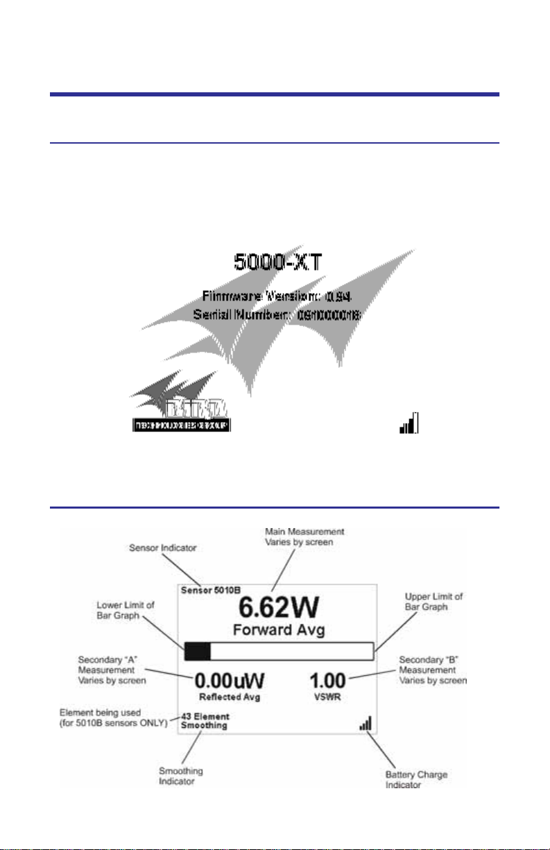
Display Description . . . . . . . . . . . . . . . . . . . . . . . . . . . . . . . . . . . . . . . . . . . . . . 4
Display Units . . . . . . . . . . . . . . . . . . . . . . . . . . . . . . . . . . . . . . . . . . . . . . . . 4
Battery Level Indicator . . . . . . . . . . . . . . . . . . . . . . . . . . . . . . . . . . . . . . . 4
Duty Cycle Indicator . . . . . . . . . . . . . . . . . . . . . . . . . . . . . . . . . . . . . . . . . 4
Analog Bar Graph . . . . . . . . . . . . . . . . . . . . . . . . . . . . . . . . . . . . . . . . . . . 4
Offset Indicator . . . . . . . . . . . . . . . . . . . . . . . . . . . . . . . . . . . . . . . . . . . . . 4
Power Indicator . . . . . . . . . . . . . . . . . . . . . . . . . . . . . . . . . . . . . . . . . . . . 4
5000-XT Initial User Interface . . . . . . . . . . . . . . . . . . . . . . . . . . . . . . . . . . . . . . 5
Startup Screen . . . . . . . . . . . . . . . . . . . . . . . . . . . . . . . . . . . . . . . . . . . . . . . 5
5000-XT Main Display Elements . . . . . . . . . . . . . . . . . . . . . . . . . . . . . . . . . 5
Chapter 2 . . . . . . . . . . . . . . . . . . . . . . . . . . . . . . . . . . . . . . Installation7
Power Supply . . . . . . . . . . . . . . . . . . . . . . . . . . . . . . . . . . . . . . . . . . . . . . . . . . . 7
AC Mains Adapter . . . . . . . . . . . . . . . . . . . . . . . . . . . . . . . . . . . . . . . . . . . . 7
Automobile Cigarette Lighter Adapter . . . . . . . . . . . . . . . . . . . . . . . . . . . 7
Connections . . . . . . . . . . . . . . . . . . . . . . . . . . . . . . . . . . . . . . . . . . . . . . . . . . . . 7
Resetting the 5000-XT . . . . . . . . . . . . . . . . . . . . . . . . . . . . . . . . . . . . . . . . . . . 10
Upgrading the Firmware . . . . . . . . . . . . . . . . . . . . . . . . . . . . . . . . . . . . . . . . . 10
xi
Page 12

Chapter 3 . . . . . . . . . . . . . . . . . . . . . . . . . . . . . . . . . . . . . . Operation13
Setting Up . . . . . . . . . . . . . . . . . . . . . . . . . . . . . . . . . . . . . . . . . . . . . . . . . . . . . 13
Shutting Down . . . . . . . . . . . . . . . . . . . . . . . . . . . . . . . . . . . . . . . . . . . . . . . . . 13
Performing a Screen Shot . . . . . . . . . . . . . . . . . . . . . . . . . . . . . . . . . . . . . . . . 13
Directional Power Sensor (DPS) . . . . . . . . . . . . . . . . . . . . . . . . . . . . . . . . . . . 14
Setting Scale . . . . . . . . . . . . . . . . . . . . . . . . . . . . . . . . . . . . . . . . . . . . . . . . 14
Terminating Power Sensor (TPS) . . . . . . . . . . . . . . . . . . . . . . . . . . . . . . . . . . 14
Zeroing Sensor . . . . . . . . . . . . . . . . . . . . . . . . . . . . . . . . . . . . . . . . . . . . . . 14
Wideband Power Sensor (WPS) . . . . . . . . . . . . . . . . . . . . . . . . . . . . . . . . . . . 15
Zeroing Sensor . . . . . . . . . . . . . . . . . . . . . . . . . . . . . . . . . . . . . . . . . . . . . . 15
Video Filter . . . . . . . . . . . . . . . . . . . . . . . . . . . . . . . . . . . . . . . . . . . . . . . . . 16
Average Mode . . . . . . . . . . . . . . . . . . . . . . . . . . . . . . . . . . . . . . . . . . . . . . 16
Peak Mode . . . . . . . . . . . . . . . . . . . . . . . . . . . . . . . . . . . . . . . . . . . . . . . . . 16
Burst Mode . . . . . . . . . . . . . . . . . . . . . . . . . . . . . . . . . . . . . . . . . . . . . . . . 16
Crest Factor Mode . . . . . . . . . . . . . . . . . . . . . . . . . . . . . . . . . . . . . . . . . . . 16
CCDF Mode . . . . . . . . . . . . . . . . . . . . . . . . . . . . . . . . . . . . . . . . . . . . . . . . 16
Chapter 4 . . . . . . . . . . . . . . . . . . . . . . . . . . . . . . Software Interfaces17
Wideband Power Sensor Attached . . . . . . . . . . . . . . . . . . . . . . . . . . . . . . . . 17
Forward Avg Interface . . . . . . . . . . . . . . . . . . . . . . . . . . . . . . . . . . . . . . . . 17
Reflected Avg Interface . . . . . . . . . . . . . . . . . . . . . . . . . . . . . . . . . . . . . . . 18
Match Interface . . . . . . . . . . . . . . . . . . . . . . . . . . . . . . . . . . . . . . . . . . . . . 19
Forward Peak Interface . . . . . . . . . . . . . . . . . . . . . . . . . . . . . . . . . . . . . . . 20
Forward Burst Interface . . . . . . . . . . . . . . . . . . . . . . . . . . . . . . . . . . . . . . 21
Crest Factor Interface . . . . . . . . . . . . . . . . . . . . . . . . . . . . . . . . . . . . . . . . 22
CCDF Interface . . . . . . . . . . . . . . . . . . . . . . . . . . . . . . . . . . . . . . . . . . . . . . 23
Main Menu Interface . . . . . . . . . . . . . . . . . . . . . . . . . . . . . . . . . . . . . . . . 24
Zero/Cal . . . . . . . . . . . . . . . . . . . . . . . . . . . . . . . . . . . . . . . . . . . . . . . . . . 24
Offset . . . . . . . . . . . . . . . . . . . . . . . . . . . . . . . . . . . . . . . . . . . . . . . . . . . . 24
Filter Menu . . . . . . . . . . . . . . . . . . . . . . . . . . . . . . . . . . . . . . . . . . . . . . . 24
CCDF Limit . . . . . . . . . . . . . . . . . . . . . . . . . . . . . . . . . . . . . . . . . . . . . . . . 24
Logging . . . . . . . . . . . . . . . . . . . . . . . . . . . . . . . . . . . . . . . . . . . . . . . . . . 25
Smoothing . . . . . . . . . . . . . . . . . . . . . . . . . . . . . . . . . . . . . . . . . . . . . . . . 25
Setup . . . . . . . . . . . . . . . . . . . . . . . . . . . . . . . . . . . . . . . . . . . . . . . . . . . . 25
Terminating Power Sensor Attached . . . . . . . . . . . . . . . . . . . . . . . . . . . . . . . 25
True Avg Power Interface . . . . . . . . . . . . . . . . . . . . . . . . . . . . . . . . . . . . . 25
Directional Power Sensor (Legacy) Attached . . . . . . . . . . . . . . . . . . . . . . . . 26
Forward Avg Interface . . . . . . . . . . . . . . . . . . . . . . . . . . . . . . . . . . . . . . . . 26
Reflected Avg Interface . . . . . . . . . . . . . . . . . . . . . . . . . . . . . . . . . . . . . . . 27
Match Interface . . . . . . . . . . . . . . . . . . . . . . . . . . . . . . . . . . . . . . . . . . . . . 28
Directional Power Sensor Attached . . . . . . . . . . . . . . . . . . . . . . . . . . . . . . . . 29
Forward Avg Interface . . . . . . . . . . . . . . . . . . . . . . . . . . . . . . . . . . . . . . . . 29
Reflected Avg Interface . . . . . . . . . . . . . . . . . . . . . . . . . . . . . . . . . . . . . . . 30
Match Interface . . . . . . . . . . . . . . . . . . . . . . . . . . . . . . . . . . . . . . . . . . . . . 31
xii
Page 13

Forward Peak Interface . . . . . . . . . . . . . . . . . . . . . . . . . . . . . . . . . . . . . . . 32
Forward Avg Peak Interface . . . . . . . . . . . . . . . . . . . . . . . . . . . . . . . . . . . 33
Main Menu Interface . . . . . . . . . . . . . . . . . . . . . . . . . . . . . . . . . . . . . . . . 34
Offset . . . . . . . . . . . . . . . . . . . . . . . . . . . . . . . . . . . . . . . . . . . . . . . . . . . . 34
Scale Menu . . . . . . . . . . . . . . . . . . . . . . . . . . . . . . . . . . . . . . . . . . . . . . . 34
Element Type . . . . . . . . . . . . . . . . . . . . . . . . . . . . . . . . . . . . . . . . . . . . . 34
Logging . . . . . . . . . . . . . . . . . . . . . . . . . . . . . . . . . . . . . . . . . . . . . . . . . . 35
Smoothing . . . . . . . . . . . . . . . . . . . . . . . . . . . . . . . . . . . . . . . . . . . . . . . . 35
Setup . . . . . . . . . . . . . . . . . . . . . . . . . . . . . . . . . . . . . . . . . . . . . . . . . . . . 35
TSTPM Sensor Attached . . . . . . . . . . . . . . . . . . . . . . . . . . . . . . . . . . . . . . . . . 35
TPS Calibration Standard Power Interface . . . . . . . . . . . . . . . . . . . . . . . 35
5000XT Main Menu, No Sensor Attached . . . . . . . . . . . . . . . . . . . . . . . . . . . 36
Log Files . . . . . . . . . . . . . . . . . . . . . . . . . . . . . . . . . . . . . . . . . . . . . . . . . . . 36
Smoothing Menu . . . . . . . . . . . . . . . . . . . . . . . . . . . . . . . . . . . . . . . . . . . . 36
Setup Menu . . . . . . . . . . . . . . . . . . . . . . . . . . . . . . . . . . . . . . . . . . . . . . . . 37
Date/Time . . . . . . . . . . . . . . . . . . . . . . . . . . . . . . . . . . . . . . . . . . . . . . . . 37
Language . . . . . . . . . . . . . . . . . . . . . . . . . . . . . . . . . . . . . . . . . . . . . . . . . 37
System Information . . . . . . . . . . . . . . . . . . . . . . . . . . . . . . . . . . . . . . . . 37
Backlight Timeout . . . . . . . . . . . . . . . . . . . . . . . . . . . . . . . . . . . . . . . . . . 37
LCD Timeout . . . . . . . . . . . . . . . . . . . . . . . . . . . . . . . . . . . . . . . . . . . . . . 38
Contrast . . . . . . . . . . . . . . . . . . . . . . . . . . . . . . . . . . . . . . . . . . . . . . . . . . 38
Update Firmware . . . . . . . . . . . . . . . . . . . . . . . . . . . . . . . . . . . . . . . . . . 38
Main Menu, Sensor Attached . . . . . . . . . . . . . . . . . . . . . . . . . . . . . . . . . . . . . 39
Offset . . . . . . . . . . . . . . . . . . . . . . . . . . . . . . . . . . . . . . . . . . . . . . . . . . . . . 39
Filter Menu . . . . . . . . . . . . . . . . . . . . . . . . . . . . . . . . . . . . . . . . . . . . . . . . . 39
CCDF Limit . . . . . . . . . . . . . . . . . . . . . . . . . . . . . . . . . . . . . . . . . . . . . . . . . 40
Log Files . . . . . . . . . . . . . . . . . . . . . . . . . . . . . . . . . . . . . . . . . . . . . . . . . . . 40
Smoothing . . . . . . . . . . . . . . . . . . . . . . . . . . . . . . . . . . . . . . . . . . . . . . . . . 40
Setup Menu . . . . . . . . . . . . . . . . . . . . . . . . . . . . . . . . . . . . . . . . . . . . . . . . 40
Language Selection Menu . . . . . . . . . . . . . . . . . . . . . . . . . . . . . . . . . . . . . . . . 41
Logging Menu . . . . . . . . . . . . . . . . . . . . . . . . . . . . . . . . . . . . . . . . . . . . . . . . . 42
Logging Date . . . . . . . . . . . . . . . . . . . . . . . . . . . . . . . . . . . . . . . . . . . . . . . 42
Logging Rate . . . . . . . . . . . . . . . . . . . . . . . . . . . . . . . . . . . . . . . . . . . . . . . . 42
Logging Duration . . . . . . . . . . . . . . . . . . . . . . . . . . . . . . . . . . . . . . . . . . . . 43
Logging Start . . . . . . . . . . . . . . . . . . . . . . . . . . . . . . . . . . . . . . . . . . . . . . . 43
Log Files . . . . . . . . . . . . . . . . . . . . . . . . . . . . . . . . . . . . . . . . . . . . . . . . . . . 43
Chapter 5 . . . . . . . . . . . . . . . . . . . . . . . . . . . . . . . . . . . . Maintenance45
Cleaning . . . . . . . . . . . . . . . . . . . . . . . . . . . . . . . . . . . . . . . . . . . . . . . . . . . . . . 45
Battery Maintenance . . . . . . . . . . . . . . . . . . . . . . . . . . . . . . . . . . . . . . . . . . . . 45
Charging Batteries . . . . . . . . . . . . . . . . . . . . . . . . . . . . . . . . . . . . . . . . . . . 45
Prolonging Battery Life . . . . . . . . . . . . . . . . . . . . . . . . . . . . . . . . . . . . . . . 45
xiii
Page 14

Conserving Battery Power . . . . . . . . . . . . . . . . . . . . . . . . . . . . . . . . . . . . 46
Conserving power during operation . . . . . . . . . . . . . . . . . . . . . . . . . . . 46
Storing a battery . . . . . . . . . . . . . . . . . . . . . . . . . . . . . . . . . . . . . . . . . . . 46
Managing Low-Battery Conditions . . . . . . . . . . . . . . . . . . . . . . . . . . . . . . 46
Identifying Low-Battery Conditions . . . . . . . . . . . . . . . . . . . . . . . . . . . 46
Resolving Low-Battery Conditions . . . . . . . . . . . . . . . . . . . . . . . . . . . . 46
Calibrating the Battery . . . . . . . . . . . . . . . . . . . . . . . . . . . . . . . . . . . . . . . 47
Battery Replacement . . . . . . . . . . . . . . . . . . . . . . . . . . . . . . . . . . . . . . . . . 47
Troubleshooting . . . . . . . . . . . . . . . . . . . . . . . . . . . . . . . . . . . . . . . . . . . . . . . . 49
Customer Service . . . . . . . . . . . . . . . . . . . . . . . . . . . . . . . . . . . . . . . . . . . . . . . 50
Parts List . . . . . . . . . . . . . . . . . . . . . . . . . . . . . . . . . . . . . . . . . . . . . . . . . . . . . . 51
Attenuators & Accessories . . . . . . . . . . . . . . . . . . . . . . . . . . . . . . . . . . . . 51
Specifications . . . . . . . . . . . . . . . . . . . . . . . . . . . . . . . . . . . . . . . . . . . . . . . . . . 52
Bird 5000-XT Digital Power Meter . . . . . . . . . . . . . . . . . . . . . . . . . . . . . . 52
General Specifications . . . . . . . . . . . . . . . . . . . . . . . . . . . . . . . . . . . . . . 52
Physical Specifications . . . . . . . . . . . . . . . . . . . . . . . . . . . . . . . . . . . . . . 53
Environmental Specifications . . . . . . . . . . . . . . . . . . . . . . . . . . . . . . . . 53
Bird 5010, 5010B, 5010T, & 5014 Directional Power Sensors . . . . . . . . 54
Bird 5011, 5015, 5011-EF and 5015-EF Terminating Sensors . . . . . . . . 56
Bird 5012B, 5016B, 5017B, 5018B, and 5019B
Wideband Power Sensors . . . . . . . . . . . . . . . . . . . . . . . . . . . . . . . . . . . . . 57
Sensor Characteristics . . . . . . . . . . . . . . . . . . . . . . . . . . . . . . . . . . . . . . 57
Average Power . . . . . . . . . . . . . . . . . . . . . . . . . . . . . . . . . . . . . . . . . . . . 58
Match Measurement . . . . . . . . . . . . . . . . . . . . . . . . . . . . . . . . . . . . . . . 58
Peak Envelope Power . . . . . . . . . . . . . . . . . . . . . . . . . . . . . . . . . . . . . . . 58
Match Measurement Uncertainty . . . . . . . . . . . . . . . . . . . . . . . . . . . . 59
Maximum Peak Power . . . . . . . . . . . . . . . . . . . . . . . . . . . . . . . . . . . . . . 60
Burst Average Power . . . . . . . . . . . . . . . . . . . . . . . . . . . . . . . . . . . . . . . 60
Crest Factor . . . . . . . . . . . . . . . . . . . . . . . . . . . . . . . . . . . . . . . . . . . . . . . 60
Complementatry Cumulative Distribution Function (CCDF) . . . . . . . . 61
Physical and Environmental Specifications . . . . . . . . . . . . . . . . . . . . . 61
ROHS . . . . . . . . . . . . . . . . . . . . . . . . . . . . . . . . . . . . . . . . . . . . . . . . . . . . . . . . . 61
Limited Warranty . . . . . . . . . . . . . . . . . . . . . . . . . . . . . . . . . . . . . . . . . 62
xiv
Page 15

Chapter 1 Introduction
Items Supplied
1. Bird Digital Power Meter (DPM)
2. Battery
Note: To install the battery see “Cust omer Service” on page 50 or
refer to the Quick Start Guide.
3. Power Supply
Note: Includes Brick, Cord, 3 In tl Adaptors, and cigare tt e adaptor
4. USB SeaLatch® Cable, 6’
5. DB9 Cable, 10’
6. Soft Case
7. Accessory Pack
8. Carabiner
9. Tri-Lingual Instruction Book on CD
10. Quick Start Guide
1
Page 16
Optional Equipment
Directional Power Sensor (DPS)
The Bird 5010B and 5014 Thruline® Sensors require
two 43 or APM/DPM elements. The DPS measures both
forward and reverse power, so VSWR and other match
measurements can be calculated and displayed.
Note: The 5010B replaces the Bird 5010. The 5010 was
only compatible with APM/DPM elements, and lacked peak-reading
capability. The 5000-XT will s till recogniz e the 5010.
Terminating Power Sensors (TPS)
The Bird 5011and 5015 series terminating power sensors do not require elements. The Bird 5011 and 5015
have a frequency range of 40 MHz – 4 GHz. The 5011EF and 5015-EF sensors have a frequency range of 40
MHz – 12 GHz.
Wideband Power Sensor (WPS)
The Bird 5012B, 5016B, 5017B, 5018B, and 5019B Thruline Sensors do not require elements. The WPS can measure average, peak, or burst power, VSWR, crest factor,
and Complementary Cumulative Distribution Function
(CCDF).
Attenuators & Accessories
A variety of attenuators and connectors for measuring
large powers with the TPS. For a complete list, see
page 51.
Soft Carry Case (P/N 5A5000-1)
Convenient and protective. Cutouts allow operation while in the case.
2
Page 17
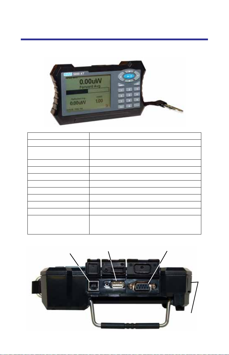
Component Description
Figure 1 Component Description
1. Period Key Input numeric values.
2. OK/Power Key Turns the DPM on or off.
3. +/- Key Toggles between positive and negative
numbers.
4. Log Key Brings up the Logging Menu.
5. Menu Key Brings up the Main Menu.
6. Arrow Keys Scrolls through menu items.
7. Numeric Keys Input numeric values.
8. USB Sensor Port Connection for power sensors.
9. COM Sensor Port Connection for power sensors.
10. USB Port Connection for computer.
11. LCD Display Backlit liquid crystal display.
12. External DC
Connector
Connect either the AC adapter or the cigarette
lighter adapter. External supplies power the
unit and charge the internal battery.
USB
Port
USB Sensor
Port
COM
Sensor Port
DC
Connector
3
Page 18
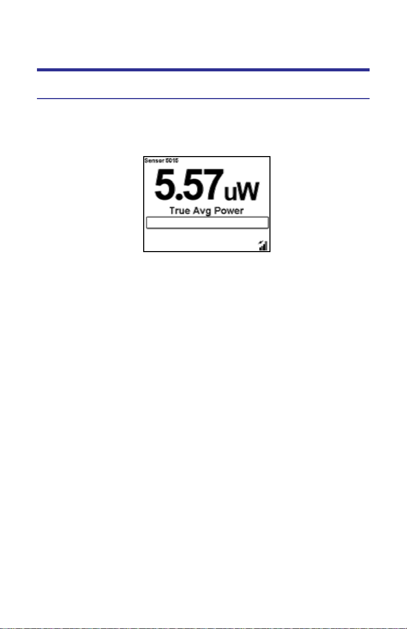
Display Description
Display Units
Shows the measurement mode and units for the display directly above.
Figure 2 Display
Battery Level Indicator
When the external adapter is connected, a lightening bolt icon will indicate the
battery is charging. The battery operates off of the external power supply unless
it is not present.
When using the internal batteries, the indicator is on continuously. When the
battery level indicator is blank, the battery needs to be recharged. If the unit is
logging when the battery becomes too low, a notification that logging is being
stopped will appear,
Duty Cycle Indicator
For burst power measurements, shows the signal’s duty cycle.
Analog Bar Graph
Displays the dynamic range of the sensor attached. Minimum and maximum
depend on sensor.
Offset Indicator
On when an offset is in use.
Power Indicator
If the power exceeds 100% of full scale, “Over” will be displayed.
The numbers in the main measurement will flash.
4
Page 19
5000-XT Initial User Interface
Startup Screen
Upon initial startup, when from complete shutdown, the splash screen will display for 5 seconds while the file system is being initialized, then it will display
the language selection screen.
Note: If this is the firs t st artup, the unit should ask f or the language
to be used.
5000-XT Main Display Elements
5
Page 20

6
Page 21

Chapter 2 Installation
Power Supply
The DPM uses a rechargeable Lithium Ion battery pack. Charge life is about 20
hours with the Bird WPS, 50 hours with other sensors.
The DPM can use an external power source. Using the DPM with the AC adapter
or the 12V cigarette lighter adapter will also charge the battery. Charging time
from full discharge is 5 hours using the AC adapter. When using the cigarette
lighter adapter, charge time will depend on the car battery charge. When the
external adapter is connected, a lightening bolt icon will indicate the battery is
charging. The battery operates off of the external power supply unless it is not
present.
AC Mains Adapter
1. Insert the adapter’s barrel connector into the DPM’s external DC connector
(See Figure 1 on page 3).
2. Insert the adapter plug into a wall receptacle.
Automobile Cigarette Lighter Adapter
1. Insert the adapter’s barrel connector into the DPM’s external DC connector.
2. Insert the adapter plug into a cigarette lighter jack.
Connections
WARNING
Never attempt to connect or disconnect RF equipment from the transmission
line while RF power is being applied.
Leaking RF energy is a potential health hazard.
Note: If the 5000-XT is connect ed to a PC when s tarting or res t arting
the PC, it may cause the boot process to lock up.
Disconnect the 5000-XT before starting or rest arting the PC.
7
Page 22
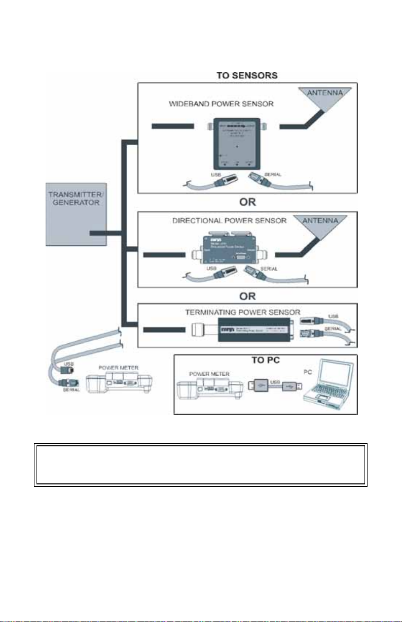
Figure 3 DPM Connections
Connecting the Directional Power Sensor (DPS)
WARNING
RF voltage may be present in RF element socket. Keep element in socket during
operation.
1. Do one of the following:
For Models 5010, 5010B, 5011, 5012, 5012A, 5012B, 5016, 5016B,
5017, 5017B, 5018, 5018B, 5019, and 5019B:
Connect the Bird DPS to the “Sensor” serial port on the DPM using the
sensor cable provided.
8
Page 23
For Models 5014:
Connect the Bird DPS to the “Sensor” USB port on the DPM using the
sensor cable provided.
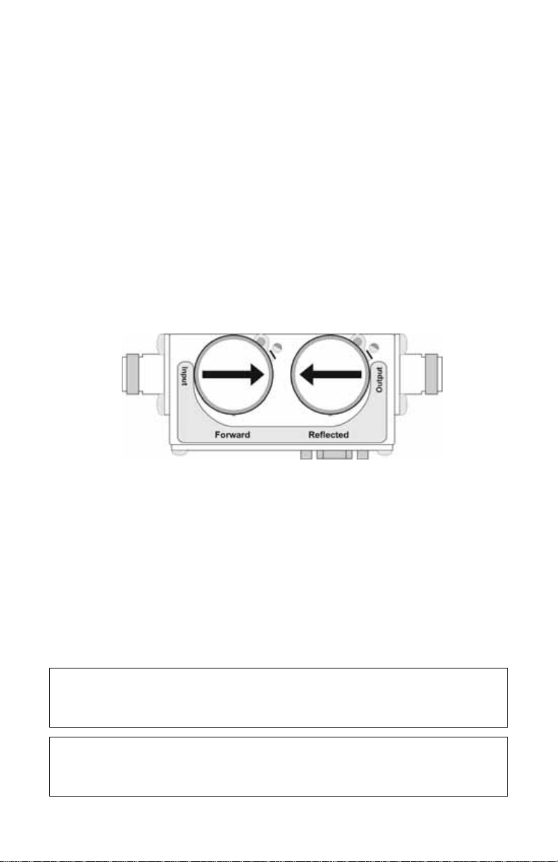
2. Connect the DPS to the RF line so that the arrow on the sensor points
towards the load.
Note: The arrow on the f orward element should poin t t owards the
load.
Note: The arrow on the reflect ed element should poin t t owards the
source.
Note: Both elements mus t be either APM/DPM or 43 types, do not
mix elements.
3. Set the power on the DPM to the forward element’s power rating.
Figure 4 DPS Element Orientation
Connecting the Wideband Power Sensor (WPS)
1. Do one of the following:
Connect the DPM port on the Bird WPS to the “Sensor” serial port on
the DPM using the sensor cable provided.
Connect the DPM port on the Bird WPS to the “Sensor” USB port on the
DPM using the sensor cable provided.
2. Connect the WPS to the RF line so that the arrow on the sensor points
towards the load.
Connecting the Terminating Power Sensor (TPS)
CAUTION
Discharge all static potentials before connecting the TPS(-EF). Electrostatic
shock could damage the sensor.
CAUTION
When connecting the TPS or the TPS-EF, only turn the connector nut. Damage
may occur if torque is applied to the sensor body.
9
Page 24

CAUTION
Do not exceed 2 W average or 125 W peak power for 5 μs when using the TPS
or the TPS-EF. Doing so will render the sensor inoperative.
Note: Connections are the same f or the Bird 5011 and 5011-EF.
1. Do one of the following:
Connect the DPM port on the Bird TPS to the “Sensor” serial port on
the DPM using the sensor cable provided.
Connect the DPM port on the Bird TPS to the “Sensor” USB port on the
DPM using the sensor cable provided.
Note: An att enuat or or directional coupler should be used with the
TPS in most applications.
Example - For an RF source with output between 0.1 and
50 W, use a 40 dB, 50 W attenuator.
2. Connect the TPS RF input to the source (using an attenuator, if appropriate).
Note: Only connect the TPS directly t o a sourc e if the RF power will
be less than 10 mW.
Resetting the 5000-XT
Pressing and holding down the 5 button for two seconds will reset the unit.
The unit will return to default settings and pop-up the language selection menu.
Upgrading the Firmware
Note: Bef ore performing this proc edure, sign on to the in ternet and
go to:
www.bird-technologies.c om/products/ software/5000-xt/
1. Power on the 5000-XT
2. Connect the USB from the 5000-XT to the PC and wait for the drive to appear.
Note: This could t ake 30 seconds
3. Create a folder named “FIRMWARE”.
Note: The f older name is case sensitive. If there is already a f older,
use the existing folder, but delete any firmware versions already in
that folder.
4. Place the updated firmware file into the folder.
Note: This file can be named an ything as long as the file extension is
.bin.
10
Page 25

5. Eject and disconnect the 5000-XT from the PC.
6. Press the Menu key.
7. Select Setup on the Main Menu.
8. Select Update Firmware on the Setup Menu. The Update Firmware file list
will display.
9. Select the newly downloaded firmware file from the list.
10. Select ACCEPT when asked “Update System Firmware?”
Note: The file will be checked. If file is corrupt, it will notify as such.
11. The following screens will be displayed:
a. “Loading” screen
b. “Erasing Flash” screen with a progress bar
c. “Writing Flash” screen with a progress bar.
d. “Update Success” screen.
12. Select OK when prompted after this message: “The system will now
power down.”.
11
Page 26

12
Page 27

Chapter 3 Operation
The Bird Digital Power Meter is very easy to operate. Once a sensor is connected, turn the DPM on and take a reading. Additional commands are available, depending on the sensor used.
Setting Up
1. Connect the sensor.
2. Turn on the DPM.
3. Set the measurement and measurement units.
Note: R ef er to the sections f ollo wing for ins tructions specific t o each
sensor .
4. Zero the sensor (WPS and TPS only).
5. Perform the following if the system loss is known or if using an attenuator:
a. Add the losses (in dB) of all components in the system.
Note: Use the loss at the measured frequency.
b. Press OFFSET and enter the total loss in dB.
Note: This will allow the user t o read the actual line power. The
DPM accepts offsets from –10 to 100 dB, depending on the sensor.
6. Turn on the RF source.
7. Take a reading.
Note: The analog bar graph will respond immediat ely to changes in
the RF power. The major and minor displays will respond after a delay
of 1 to 13 seconds, depending on the level of smoothing.
Shutting Down
Press and Hold the “OK” key for 2 seconds. This will put the unit into
Sleep mode. It will stop logging in this mode.
Press and hold the “OK” key until the “OK” key illuminates, approxi-
mately 8 seconds. Release the key after it illuminates. This will shut the
unit down completely.
Performing a Screen Shot
1. Press and hold <.> for two seconds will perform a screen shot of the current
screen on the DPM.
2. Select OK to confirm the screen shot.
Note: The image file name will be displayed.
13
Page 28

Directional Power Sensor (DPS)
WARNING
RF voltage may be present in RF element socket. Keep element in socket
during operation.
Setting Scale
Note: The Bird DPS uses Bird Plug-In Elemen ts. These are labeled
with a max power and a frequency range.
Note: The transmitt er frequency should be within the
element range.
Note: Forward and Reflected full scale power must be entered
manually.
1. Press Scale.
2. Select the power units (W, mW or kW) with up and down arrow keys.
3. Enter the maximum power of the element in the forward element socket
using the numeric keypad and <.> key.
Note: The element’s max power is listed on the element nameplate.
4. Press OK.
Terminating Power Sensor (TPS)
CAUTION
Do not exceed 2 W average or 125 W peak power for 5 μs when using the TPS
or the TPS-EF. Doing so will render the sensor inoperative.
Zeroing Sensor
Over time, the sensor’s “zero value” (reading with no applied RF power) can
drift due to environmental factors (temperature, humidity, etc.) This can make
the readings performed by this sensor less accurate by the drift value. If the drift
would be a significant error, re zero the sensor.
1. Ensure the sensor has been connected to the DPM.
2. Press and hold “0” for two seconds to begin zero calibration.
Note: “Z ero/Cal” will be displayed and calibration will begin.
14
Page 29

Note: Z eroing the sensor takes 60 sec onds. The bar graph will display
calibration progress.
Note: When comple te, “PASS” should be displayed.
3. Press Enter to return to normal operation when zeroing is complete.
Note: If “FAIL” is displayed, mak e sure no RF power is applied t o the
sensor and perform the procedure again.
TPS-EF
The Bird TPS-EF uses frequency correction factors to allow more accurate measurements. Look at the label on the side of the sensor and find the correction
factor for the frequency being measured. Add the correction factor to the other
attenuation or coupling factors and enter this as an offset.
Wideband Power Sensor (WPS)
A status LED on the front lights when the WPS is powered, and blinks when the
WPS is connected to the DPM.
Zeroing Sensor
Over time, the sensor’s “zero value” (reading with no applied RF power) can
drift due to environmental factors (temperature, humidity, etc.) This can make
the readings performed by this sensor less accurate by the drift value. If the drift
would be a significant error, re zero the sensor.
1. Make sure the sensor has reached a stable operating temperature.
2. Make sure no RF power is applied to the sensor.
3. Press and hold “0” for two seconds to begin zero calibration.
WARNING
Do not interrupt the calibration.
Note: “Z ero/Cal” will be displayed and calibration will begin.
Note: Z eroing the sensor takes 60 sec onds. The bar graph will display
calibration progress.
Note: When comple te, “PASS” should be displayed.
4. Press Enter to return to normal operation when zeroing is complete.
Note: c.If “FAIL” is displayed, make sure no RF power is applied to
the sensor and perform the procedure again.
15
Page 30

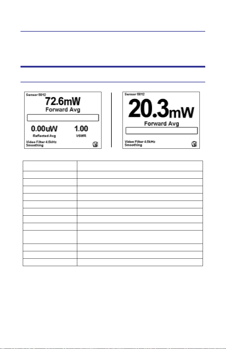
Video Filter
Except for average power and VSWR measurements, all measurements use a
variable video filter to improve accuracy. This filter can be set to either 4.5 kHz,
400 kHz, or Full bandwidth.
Note: It should be as narrow as possible while s till being larger than
the demodulated signal bandwidth (video bandwidth). Narrowing the
filter limits the noise contribution from interf ering signals.
Listed below are some common modulation schemes and the appropriate video filter.
Video Filter Modulation Type
4.5 kHz CW Burst (Burst width > 150 s), Voice Band
AM, FM, Phase Modulation, Tetra
400 kHz CW Burst (b.w. > 3 s), GSM, 50 kHz AM,
DQPSK (¼, symbol rate < 24 k/s)
Full Bandwidth CW Burst (b.w. > 200 ns), CDMA, WCDMA,
DQPSK (¼, symbol rate < 200 k/s), DAB/DVB-T
Average Mode
This mode displays the average forward and reflected power.
Note: In average mode, the VS WR or sys tem match can be displayed
instead of the reflected power.
Peak Mode
This mode displays the peak envelope power.
Burst Mode
This mode displays the average power in a burst. The burst’s duty cycle is measured by the DPM.
Crest Factor Mode
The crest factor is the ratio of the forward peak power and the forward average
power. It is measured in dB.
Note: There are no additional c ontrols in this mode.
CCDF Mode
The CCDF measures the percentage of time the power level is above a threshold. To set the power threshold:
1. Press menu.
2. Select CCDF Limit from the Main Menu.
3. Enter new value.
16
Page 31
Chapter 4 Software Interfaces
Wideband Power Sensor Attached
Forward Avg Interface
Small Display
\
Large Display
Key Button Action
Right Arrow Changes the Main Measurement to Reflected Avg
Left Arrow Changes the Main Measurement to the CCDF
Up Arrow Toggles Fwd Avg units from W to dBm
Down Arrow Toggles Fwd Avg units from W to dBm
OK Button Initiates Shutdown. See “Shutting Down” on page 13
Menu Button Goes to Main Menu
Log Button Goes to Logging submenu
+/- Toggles between “Small” and “Large” Display
. (2 Sec) Performs a screen shot. See “Performing a Screen
Shot” on page 13
0 (2 Sec) Zero/Cal Unit/Sensor
8 (2 Sec) Turn On/Off Smoothing
Menu & Log (2 sec) Language Selection Screen
Note: The main measuremen t is in the larger display located
above the graph bar. The two smaller, secondary measurements
are located below the graph bar. All of these measurements vary
depending on the main measurement displayed.
17
Page 32

Reflected Avg Interface
Small Display
Large Display
Key Button Action
Right Arrow Changes the Main Measurement to Match
Left Arrow Changes the Main Measurement to Forward Avg
Up Arrow Toggles Rfl Avg units from W to dBm
Down Arrow Toggles Rfl Avg units from W to dBm
OK Button Initiates Shutdown. See “Shutting Down” on
page 13
Menu Button Goes to Main Menu
Log Button Goes to Logging submenu
+/- Toggles between “Small” and “Large” Display
. (2 Sec) Performs a screen shot. See “Performing a Screen
Shot” on page 13
0 (2 Sec) Zero/Cal Unit/Sensor
8 (2 Sec) Turn On/Off Smoothing
Menu & Log (2 sec) Language Selection Screen
Note: The main measuremen t is in the larger display located
above the graph bar. The two smaller, secondary measurements
are located below the graph bar. All of these measurements vary
depending on the main measurement displayed.
18
Page 33

Match Interface
Small Display
Large Display
Key Button Action
Right Arrow Changes the Main Measurement to Forward Peak
Left Arrow Changes the Main Measurement to Reflected Avg
Up Arrow Switch Match (VSWR, Rtn Loss, Match Eff%)
Down Arrow Switch Fwd/Rfl Avg (W, dBm)
OK Button Initiates Shutdown. See “Shutting Down” on
page 13
Menu Button Goes to Main Menu
Log Button Goes to Logging submenu
+/- Toggles between “Small” and “Large” Display
. (2 Sec) Performs a screen shot. See “Performing a Screen
Shot” on page 13
0 (2 Sec) Zero/Cal Unit/Sensor
8 (2 Sec) Turn On/Off Smoothing (*for Fwd/Rfl Power)
Menu & Log (2 sec) Language Selection Screen
Note: The main measuremen t is in the larger display located
above the graph bar. The two smaller, secondary measurements
are located below the graph bar. All of these measurements vary
depending on the main measurement displayed.
19
Page 34

Forward Peak Interface
Small Display
Large Display
Key Button Action
Right Arrow Changes the Main Measurement to Forward Burst
Left Arrow Changes the Main Measurement to Match
Up Arrow Switch Fwd Peak (W, uW, mW, kW, dBm)
Down Arrow Switch Fwd Avg Power (W, uW, mW, kW, dBm
OK Button Initiates Shutdown. See “Shutting Down” on
page 13
Menu Button Goes to Main Menu
Log Button Goes to Logging submenu
+/- Toggles between “Small” and “Large” Display
. (2 Sec) Performs a screen shot. See “Performing a Screen
Shot” on page 13
0 (2 Sec) Zero/Cal Unit/Sensor
8 (2 Sec) Turn On/Off Smoothing (*for Fwd Avg)
Menu & Log (2 sec) Language Selection Screen
* - ‘This mode displays the peak envelope power.
Note: The main measuremen t is in the larger display located
above the graph bar. The two smaller, secondary measurements
are located below the graph bar. All of these measurements vary
depending on the main measurement displayed.
20
Page 35

Forward Burst Interface
Small Display Large Display
Key Button Action
Right Arrow Changes the Main Measurement to Crest Factor
Left Arrow Changes the Main Measurement to Forward Peak
Up Arrow Switch Burst Power (W, uW, mW, kW, dBm)
Down Arrow Switch Fwd Avg Power (W, uW, mW, kW, dBm)
OK Button Initiates Shutdown. See “Shutting Down” on
page 13
Menu Button Goes to Main Menu
Log Button Goes to Logging submenu
+/- Toggles between “Small” and “Large” Display
. (2 Sec) Performs a screen shot. See “Performing a Screen
Shot” on page 13
0 (2 Sec) Zero/Cal Unit/Sensor
8 (2 Sec) Turn On/Off Smoothing* (for Fwd Avg)
Menu & Log (2 sec) Language Selection Screen
* - Burs t mode displays the A verage po wer in a burst. The burs t’ s duty
cycle is measured burst width/period.
Note: The main measuremen t is in the larger display located
above the graph bar. The two smaller, secondary measurements
are located below the graph bar. All of these measurements vary
depending on the main measurement displayed.
21
Page 36

Crest Factor Interface
Small Display
Large Display
Key Button Action
Right Arrow Changes the Main Measurement to CCDF
Left Arrow Changes the Main Measurement to Forward Burst
Up Arrow Switch Fwd Ave (W, uW, mW, kW, dBm)
Down Arrow Switch Rfl Ave (W, uW, mW, kW, dBm)
OK Button Initiates Shutdown. See “Shutting Down” on
page 13
Menu Button Goes to Main Menu
Log Button Goes to Logging submenu
+/- Toggles between “Small” and “Large” Display
. (2 Sec) Performs a screen shot. See “Performing a Screen
Shot” on page 13
0 (2 Sec) Zero/Cal Unit/Sensor
8 (2 Sec) Turn On/Off Smoothing (*for Fwd Avg)
Menu & Log (2 sec) Language Selection Screen
* - Cres t Fact or is the ratio of the f orward peak power and the forward
Average power. It is measured in dB.
Note: The main measuremen t is in the larger display located
above the graph bar. The two smaller, secondary measurements
are located below the graph bar. All of these measurements vary
depending on the main measurement displayed.
22
Page 37

CCDF Interface
Small Display
Large Display
Key Button Action
Right Arrow Changes the Main Measurement to Forward Avg
Left Arrow Changes the Main Measurement to Crest Factor
Up Arrow Switch between Forward Peak/Forward Average
Down Arrow Switch Fwd Peak/Ave (W, uW, mW, kW, dBm)
OK Button Initiates Shutdown. See “Shutting Down” on
page 13
Menu Button Goes to Main Menu
Log Button Goes to Logging submenu
+/- Toggles between “Small” and “Large” Display
. (2 Sec) Performs a screen shot. See “Performing a Screen
Shot” on page 13
0 (2 Sec) Zero/Cal Unit/Sensor
8 (2 Sec) Turn On/Off Smoothing
Menu & Log (2 sec) Language Selection Screen
* - CCDF measures the percen t age of time the power level is abo ve a
threshold.
Note: The main measuremen t is in the larger display located
above the graph bar. The two smaller, secondary measurements
are located below the graph bar. All of these measurements vary
depending on the main measurement displayed.
23
Page 38

Main Menu Interface
Note: To reach this screen, press the Menu button.
Zero/Cal
Begins a zero calibration on the sensor.
Offset
Sets the Offset for the measurement.
Filter Menu
Sets the filter tolerance level.
CCDF Limit
Sets the CCDF limit.
24
Page 39

Logging
See “Log Files” on page 36.
Smoothing
See “Smoothing Menu” on page 36.
Setup
See “Setup Menu” on page 37.
Terminating Power Sensor Attached
Note: Includes the Ext ended Frequency versions.
True Avg Power Interface
Key Button Action
Right Arrow No effect
Left Arrow No effect
Up Arrow Toggles Fwd Avg units from W to dBm
Down Arrow Toggles Fwd Avg units from W to dBm
OK Button Initiates Shutdown. See “Shutting Down” on
page 13
Menu Button Goes to Main Menu
Log Button Goes to Logging submenu
0 (2 Sec) Zero/Cal Unit/Sensor
8 (2 Sec) Turn On/Off Smoothing
. (2 Sec) Performs a screen shot. See “Performing a Screen
Shot” on page 13
Menu & Log (2 sec) Language Selection Screen
25
Page 40

Directional Power Sensor (Legacy) Attached
Forward Avg Interface
Small Display
Large Display
Key Button Action
Right Arrow Changes the Main Measurement to Reflected Avg
Left Arrow Changes the Main Measurement to Match
Up Arrow Switch True Avg (W, uW, mW, kW, dBm)
Down Arrow Switch True Avg (W, uW, mW, kW, dBm)
OK Button Initiates Shutdown. See “Shutting Down” on
page 13
Menu Button Goes to Main Menu
Log Button Goes to Logging submenu
+/- Toggles between “Small” and “Large” Display
. (2 Sec) Performs a screen shot. See “Performing a Screen
Shot” on page 13
0 (2 Sec) No effect
8 (2 Sec) Turn On/Off Smoothing
Menu & Log (2 sec) Language Selection Screen
* - 5010 only supports APM/DPM Elemen ts – No Element Type Select on
Menu.
Note: The main measuremen t is in the larger display located
above the graph bar. The two smaller, secondary measurements
are located below the graph bar. All of these measurements vary
depending on the main measurement displayed.
26
Page 41

Reflected Avg Interface
Small Display
Large Display
Key Button Action
Right Arrow Changes the Main Measurement to Match
Left Arrow Changes the Main Measurement to Forward Avg.
Up Arrow Switch True Avg (W, uW, mW, kW, dBm)
Down Arrow Switch True Avg (W, uW, mW, kW, dBm)
OK Button Initiates Shutdown. See “Shutting Down” on
page 13.
Menu Button Goes to Main Menu.
Log Button Goes to Logging submenu.
+/- Toggles between “Small” and “Large” Display.
. (2 Sec) Performs a screen shot. See “Performing a Screen
Shot” on page 13.
0 (2 Sec) No effect
8 (2 Sec) Turn On/Off Smoothing
Menu & Log (2 sec) Language Selection Screen
* - 5010 only supports APM/DPM Elemen ts – No Element Type Select on
Menu.
Note: The main measuremen t is in the larger display located
above the graph bar. The two smaller, secondary measurements
are located below the graph bar. All of these measurements vary
depending on the main measurement displayed.
27
Page 42

Match Interface
Small Display
Large Display
Key Button Action
Right Arrow Goes to Forward Avg measurement
Left Arrow Goes to Reflected Avg measurement
Up Arrow Switch Match (VSWR, Rtn Loss, Match Eff%)
Down Arrow Switch Fwd/Rfl Avg (W, dBm)
OK Button Initiates Shutdown. See “Shutting Down” on
page 13
Menu Button Goes to Main Menu
Log Button Goes to Logging submenu
+/- Toggles between “Small” and “Large” Display
. (2 Sec) Performs a screen shot. See “Performing a Screen
Shot” on page 13
0 (2 Sec) No effect
8 (2 Sec) Turn On/Off Smoothing
Menu & Log (2 sec) Language Selection Screen
* - 5010 only supports APM/DPM Elemen ts – No Element Type Select on
Menu.
Note: The main measuremen t is in the larger display located
above the graph bar. The two smaller, secondary measurements
are located below the graph bar. All of these measurements vary
depending on the main measurement displayed.
28
Page 43

Directional Power Sensor Attached
Forward Avg Interface
Small Display
Large Display
Key Button Action
Right Arrow Changes the Main Measurement to Forward Avg Peak
Left Arrow Changes the Main Measurement to Reflected Avg
Up Arrow Switch True Avg (W, uW, mW, kW, dBm)
Down Arrow Switch True Avg (W, uW, mW, kW, dBm)
OK Button Initiates Shutdown. See “Shutting Down” on
page 13
Menu Button Goes to Main Menu
Log Button Goes to Logging submenu
+/- Toggles between “Small” and “Large” Display
. (2 Sec) Performs a screen shot. See “Performing a Screen
Shot” on page 13
0 (2 Sec) No effect
8 (2 Sec) Turn On/Off Smoothing
Menu & Log (2 sec) Language Selection Screen
Note: The main measuremen t is in the larger display located
above the graph bar. The two smaller, secondary measurements
are located below the graph bar. All of these measurements vary
depending on the main measurement displayed.
29
Page 44

Reflected Avg Interface
Small Display
Large Display
Key Button Action
Right Arrow Changes the Main Measurement to Forward Avg
Left Arrow Changes the Main Measurement to Match
Up Arrow Switch True Avg (W, uW, mW, kW, dBm)
Down Arrow Switch True Avg (W, uW, mW, kW, dBm)
OK Button Initiates Shutdown. See “Shutting Down” on
page 13
Menu Button Goes to Main Menu
Log Button Goes to Logging submenu.
+/- Toggles between “Small” and “Large” Display
. (2 Sec) Performs a screen shot. See “Performing a Screen
Shot” on page 13
0 (2 Sec) No effect
8 (2 Sec) Turn On/Off Smoothing
Menu & Log (2 sec) Language Selection Screen
Note: The main measuremen t is in the larger display located
above the graph bar. The two smaller, secondary measurements
are located below the graph bar. All of these measurements vary
depending on the main measurement displayed.
30
Page 45

Match Interface
Small Display
Large Display
Key Button Action
Right Arrow Changes the Main Measurement to Forward Peak
Left Arrow Changes the Main Measurement to Reflected Avg
Up Arrow Switch Match (VSWR, Rtn Loss, Match Eff%)
Down Arrow Switch Fwd/Rfl Avg (W, dBm)
OK Button Initiates Shutdown. See “Shutting Down” on
page 13
Menu Button Goes to Main Menu
Log Button Goes to Logging submenu
+/- Toggles between “Small” and “Large” Display
. (2 Sec) Performs a screen shot. See “Performing a Screen
Shot” on page 13
0 (2 Sec) No effect
8 (2 Sec) Turn On/Off Smoothing
Menu & Log (2 sec) Language Selection Screen
Note: The main measuremen t is in the larger display located
above the graph bar. The two smaller, secondary measurements
are located below the graph bar. All of these measurements vary
depending on the main measurement displayed.
31
Page 46

Forward Peak Interface
Key Button Action
Right Arrow Changes the Main Measurement to Forward Avg
Peak
Left Arrow Changes the Main Measurement to Match
Up Arrow Switch True Avg (W, uW, mW, kW, dBm)
Down Arrow Switch True Avg (W, uW, mW, kW, dBm)
OK Button Initiates Shutdown. See “Shutting Down” on
page 13
Menu Button Goes to Main Menu
Log Button Goes to Logging submenu
+/- Toggles between “Small” and “Large” Display
. (2 Sec) Performs a screen shot. See “Performing a Screen
Shot” on page 13
0 (2 Sec) No effect
8 (2 Sec) Turn On/Off Smoothing
Menu & Log (2 sec) Language Selection Screen
Note: The main measuremen t is in the larger display located
above the graph bar. The two smaller, secondary measurements
are located below the graph bar. All of these measurements vary
depending on the main measurement displayed.
32
Page 47

Forward Avg Peak Interface
Key Button Action
Right Arrow Changes the Main Measurement to Forward Avg
Left Arrow Changes the Main Measurement to Forward Peak
Up Arrow Switch True Avg (W, uW, mW, kW, dBm)
Down Arrow Switch True Avg (W, uW, mW, kW, dBm)
OK Button Initiates Shutdown. See “Shutting Down” on
page 13
Menu Button Goes to Main Menu
Log Button Goes to Logging submenu
+/- Toggles between “Small” and “Large” Display
. (2 Sec) Performs a screen shot. See “Performing a Screen
Shot” on page 13
0 (2 Sec) No effect
8 (2 Sec) Turn On/Off Smoothing
Menu & Log (2 sec) Language Selection Screen
Note: The main measuremen t is in the larger display located
above the graph bar. The two smaller, secondary measurements
are located below the graph bar. All of these measurements vary
depending on the main measurement displayed.
33
Page 48

Main Menu Interface
Note: To reach this screen, press the Menu button.
Offset
Sets the Offset for the measurement.
Scale Menu
Sets the scale.
Element Type
Toggle between 43 and APM/DPM Element types.
34
Page 49

Logging
See “Log Files” on page 36.
Smoothing
See “Smoothing Menu” on page 36.
Setup
See “Setup Menu” on page 37.
TSTPM Sensor Attached
TPS Calibration Standard Power Interface
Key Button Action
Right Arrow No effect
Left Arrow No effect
Up Arrow Switch True Avg (W, uW, mW, kW, dBm)
Down Arrow Switch True Avg (W, uW, mW, kW, dBm)
Ok Button Selects language and change all screens to reflect
the language selected
Menu Button Goes to Main Menu
Log Button Goes to Logging submenu
OK (2 Sec) Initiates Shutdown. See “Shutting Down” on
page 13
. (2 Sec) Performs a screen shot. See “Performing a Screen
Shot” on page 13
0 (2 Sec) Zero/Cal Unit/Sensor
8 (2 Sec) Turn On/Off Smoothing
Menu & Log (2 sec) Language Selection Screen
Note: The main measuremen t is in the larger display locat ed above
the graph bar . The two smaller, secondary measurements are located
below the graph bar. All of these measurements vary depending on
the main measurement displayed.
35
Page 50

5000XT Main Menu, No Sensor Attached
Key Button Action
Right Arrow No effect.
Left Arrow Return to Start Screen.
Up Arrow Up through menu
Down Arrow Down through menu
OK Button Select highlighted.
Menu Button No effect.
Log Button No effect.
. (2 Sec) Performs a screen shot. See “Performing a Screen Shot”
on page 13.
Ok (2 Sec) Initiates Shutdown. See “Shutting Down” on page 13.
Log Files
Lists the stored log files. Pressing the “OK” button will delete the selected file.
Logfiles are named using date/time YYYYMMDDHHMMSS.XML
Smoothing Menu
Sets smoothing feature.
36
Page 51

Setup Menu
Controls all the preferences of the DPM.
Date/Time
Sets the date and time.
The Up and Down arrows control the settings.
The “OK” button locks the settings.
Language
See “Language Selection Menu” on page 41.
System Information
Lists the information regarding firmware, serial number of the unit, as well as
battery and drive capacities.
Backlight Timeout
Sets the amount of time before the backlight shuts down.
The Up and Down arrows control the settings.
The “OK” button locks the settings.
37
Page 52
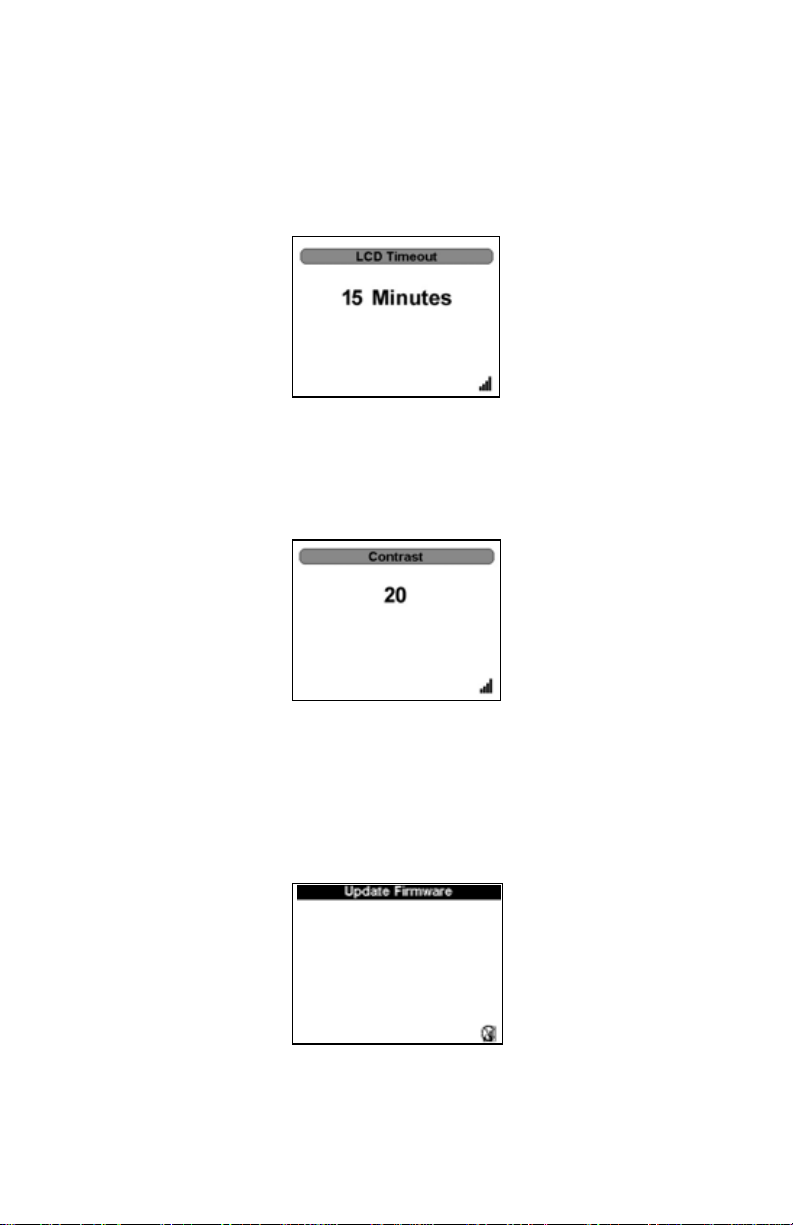
LCD Timeout
Sets the amount of time before the LCD shuts down.
The Up and Down arrows control the settings.
The “OK” button locks the settings.
Contrast
Sets the contrast of the display.
The Up and Down arrows control the settings.
The “OK” button locks the settings.
Update Firmware
Updates the firmware of the DPM.
Note: A connection t o a PC must be made bef ore updating can be
done. Disconnect from the PC, though, before file operations, such as
logging, are done. If logging when connected to a PC, the logging is
automatically stopped.
38
Page 53

Main Menu, Sensor Attached
Key Button Action
Right Arrow No effect.
Left Arrow Return to Start Screen.
Up Arrow Up through menu
Down Arrow Down through menu
OK Button Select highlighted.
Menu Button No effect.
Log Button No effect.
. (2 Sec) Performs a screen shot. See “Performing a Screen Shot”
on page 13.
Ok (2 Sec) Initiates Shutdown. See “Shutting Down” on page 13.
Offset
Sets offset.
Filter Menu
Controls the filter.
39
Page 54

CCDF Limit
Sets the CCDF Limit.
Log Files
Opens access to the log files.
Smoothing
Sets the Smoothing.
Setup Menu
Controls all the preferences of the DPM.
40
Page 55

Language Selection Menu
Note:
This screen appears
either when the unit is
turned on for the first
time or when the unit
has been reset (see
“Resetting the 5000-XT”
on page 10).
Key Button Action
Right Arrow No effect.
Left Arrow Return to Main Menu
Up Arrow Up through menu
Down Arrow Down through menu
Ok Button Select language and change all screens to reflect
the language selected
Menu Button No effect.
Log Button No effect.
. (2 Sec) Performs a screen shot. See “Performing a Screen
Shot” on page 13.
OK (2 Sec) Initiates Shutdown. See “Shutting Down” on
page 13.
41
Page 56

Logging Menu
Logging Date
Key Button Action
Right Arrow Cycles through onscreen fields
Left Arrow Cycles through onscreen fields
Up Arrow Adjusts Date and Time setting
Down Arrow Adjusts Date and Time setting
OK Button Confirms the setting and moves to the next screen.
Numeric Keypad Directly inputs date and time.
Logging Rate
Key Button Action
Right Arrow
Left Arrow
Up Arrow Cycles through onscreen fields
Down Arrow Cycles through onscreen fields
OK Button Confirms the setting and moves to the next screen.
Numeric Keypad
42
Page 57

Logging Duration
Key Button Action
Right Arrow
Left Arrow
Up Arrow Cycles through onscreen fields
Down Arrow Cycles through onscreen fields
OK Button Confirms the setting and moves to the next screen.
Numeric Keypad
Logging Start
Key Button Action
Right Arrow Cycles through onscreen fields
Left Arrow Cycles through onscreen fields
Up Arrow
Down Arrow
OK Button Confirms the setting and moves to the next screen.
Numeric Keypad
Note: The “OK” but t on will blink when logging.
Log Files
See “Log Files” on page 36.
43
Page 58

44
Page 59

Chapter 5 Maintenance
Cleaning
CAUTION
Do not use harsh or abrasive detergents for cleaning.
Clean the Bird Digital Power Meter and its display with a soft cloth dampened
with mild detergent and water only. Clean sensors with a dry cleaning solvent
that leaves no residue.
Battery Maintenance
Charging Batteries
Fully charged batteries provide about 20 hours of continuous operation with the
Bird WPS, 50 hours with other sensors. Charging time is typically 5 hours using the
AC adapter. The batteries charge whenever the DPM is connected to AC or DC
power sources, using either the AC Mains adapter or the automobile cigarette
lighter adapter. When the external adapter is connected, the battery level indicator will blink until the battery is fully charged. When using the internal batteries,
the indicator will be on continuously and the black bar will show the battery
change remaining. The unit will charge with its power turned either on or off.
Note: F or optimum bat tery lif e, only charge the batt eries after the
battery level indicator empties complet ely and begins to blink.
Prolonging Battery Life
To prolong battery life and optimize the accuracy of battery charge displays:
Charge the battery while the DPM is plugged into external power
through the AC adapter.
Charge it fully before turning on.
The battery charges whether the DPM is off or in use, but the battery
charges faster while the DPM is off.
Charging may be delayed if a battery is new, has been unused for 2
weeks or more, or is much warmer or cooler than room temperature.
45
Page 60

Conserving Battery Power
Conserving power during operation
Disconnect external devices that you are not using that are not plugged
into an external power source.
Stop, disable, or remove any sensors that you are not using.
If left alone, initiate Sleep mode or shut down completely.
Storing a battery
CAUTION
To prevent damage to a battery pack, do not expose it to high temperatures
for extended periods of time.
If the 5000-XT will be unused and unplugged from external power for
more than 2 weeks, remove the battery and store it separately.
To prolong the charge of a stored battery pack, place it in a cool, dry
place.
Calibrate a battery pack before using it if it has been stored for one
month or more.
Managing Low-Battery Conditions
The information in this section describes the alerts and system responses set at
the factory.
Identifying Low-Battery Conditions
The battery power indicator shows the battery power level is low.
Resolving Low-Battery Conditions
When External Power is Available - To resolve a low-battery condition
when external power is available, connect one of the following:
AC adapter
Optional expansion product
Optional power adapter
When a Charged Battery is Available - To resolve a low-battery condition
when a charged battery is available:
1. Shut down the 5000-XT. See “Shutting Down” on page 13.
2. Insert a charged battery pack.
3. Turn on the the 5000-XT.
46
Page 61

When No Power Source is Available - To resolve a low-battery condition
when no power source is available:
Initiate sleep mode. See “Shutting Down” on page 13.
Log trace (see “Logging Menu” on page 42)and turn off the 5000-XT
(see “Shutting Down” on page 13).
When the 5000-XT Cannot Restore from Sleep Mode - To resolve a low-
battery condition when the DPM lacks the power to restore from sleep mode:
1. Do one of the following:
Insert a charged battery (see “Battery Replacement” on page 47).
Plug the computer into an external power source (see “Charging Bat-
teries” on page 45).
2. Restore from hibernation by pressing the power button.
Calibrating the Battery
Note: E ven if a bat tery pack is heavily used, it should not be neces-
sary to calibrate it more than once a month.
Note: It is not necessary t o calibrat e a new bat tery pack.
Note: Calibrat e a battery pack under the f ollowing conditions:
When battery charge displays seem inaccurate
When there is a significant change in battery run time
When the battery has been unused for one month or more
1. Charge the battery. See “Charging Batteries” on page 45.
2. Discharge the battery fully through normal use.
3. Recharge the battery. See “Charging Batteries” on page 45.
Battery Replacement
The Lithium Ion (Li18S) batteries do not normally need to be replaced. If necessary, however, follow these instructions (see Figure 5).
WARNING
Disconnect from external power before any disassembly.
The potential for electric shock exists.
47
Page 62
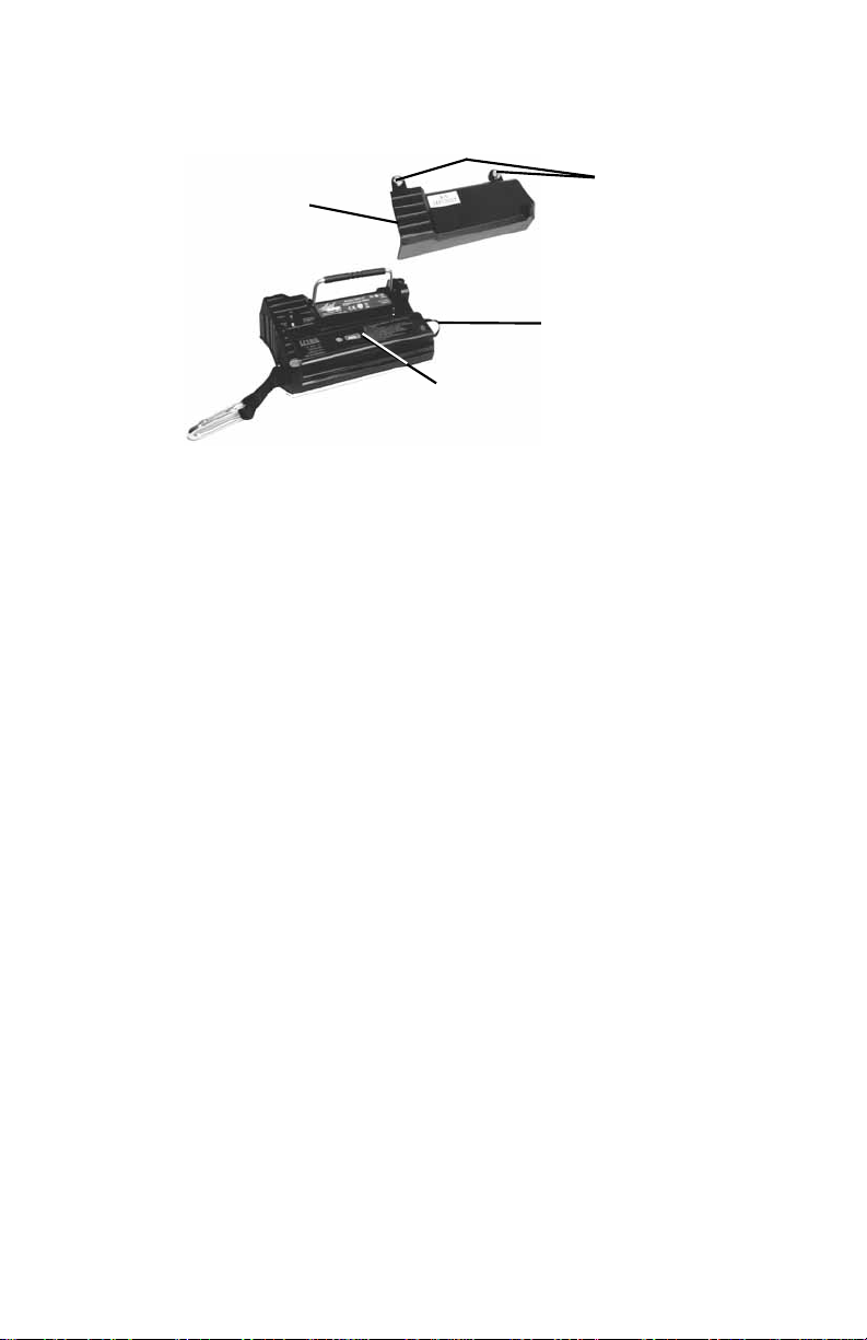
Figure 5 Back Cover Removal
Back
Cover
Battery
Strap
Battery
1. Lay the DPM, display side down, on a clean surface.
2. Remove the two mounting screws from the back cover.
3. Remove the back cover.
Note: Take care to not disconnect the bat tery c onnector.
4. Pull the battery strap and remove the old battery.
5. Install the new battery.
Note: Check the orien tation of the positive and negative t erminals.
6. Replace the back cover.
7. Secure the back cover with the mounting screws.
Mounting
Screws
48
Page 63

Troubleshooting
PROBLEM POSSIBLE CAUSE REMEDY
Nothing
shown on
display
Display shows
Start Screen
when sensor
is attached.
Display shows
dashes and
“Overrange”;
bar scale is full
WPS Status
LED is not on
Erratic power
readings
Unit is off Press and hold the OK key unitl
the key is illuminated blue.
Batteries are drained Use external power source (see
“Power Supply” on page 7)
Replace the batteries (see
“Customer Service” on page 50)
Sensor communication
has failed
Unit is overrange Use higher power elements (if
WPS not powered Check connection to DPM
Element contact out of
alignment (DPS)
Check connection to DPM.
Use a different cable.
Use a different sensor.
applicable), or reduce RF power.
Connect WPS to a power supply
using the AC adapter
Align the contact. It must be far
enough out to make good
contact with the element, but
must not restrict entry of the
element body.
PC locks when
booting with
the 5000-XT
connected.
Damaged element
(DPS)
Sensor has lost its zero
(TPS)
Sensor is damaged Replace sensor.
Incorrect BIOS settings
on PC.
Replace element.
Rezero sensor.
Disconnect the unit from the PC
then reboot.
49
Page 64

Customer Service
Any maintenance or service procedure beyond the scope of those in this chapter should be referred to a qualified service center.
If you need to return the unit for any reason, request an RMA through the Bird
Technologies website (link shown below). All instruments returned must be
shipped prepaid and to the attention of the RMA number.
Bird Service Center
30303 Aurora Road
Cleveland (Solon), Ohio 44139-2794
Fax: (440) 248-5426
E-mail: bsc@bird-technologies.com
For the location of the Sales Office nearest you, visit our website at:
http://www.bird-technologies.com
50
Page 65

Parts List
Part Name Part Number
Digital Power Meter 5000-XT
Battery, Installed 5A5001-1
Power Supply, Includes Brick, Cord, 3
Intl Adaptors 5A5002-1
Cigarette Lighter Adapter 5A2238-4
Directional Power Sensor 5010, 5010B & 5014
DPM Elements
See P/N 871-DPM-019-901,
the DPM Element Guide,
for a complete list of elements
Terminating Power Sensor
40 MHz – 4 GHz
40 MHz – 12 GHz
Wideband Power Sensor 5012, 5012A, 5012B,
Soft Carry Case 5A5000-1
Lanyard 5A5000-2
Carabiner 5A5000-3
Hard Carry Case 5000-035
PC Interface
Virtual Power Meter (WPS) VPM
Serial to USB Adapter DC-DB9-U
Instruction manual 920-5000-XT
Quick Start Guide 920-5000-XT-QSG
Attenuators & Accessories
Various
5011 & 5015
5011-EF & 5015-EF
5016, 5016B, 5017,
5017B, 5018, 5018B,
5019, & 5019B
N(F) – N(M) Attenuators (RF power range with TPS)
30 dB (10 mW – 10 W)
40 dB (100 mW – 50 W)
DC Block 5011A035–1
N(F) – N(M) Test Cable, 1.5 m TC–MNFN–1.5–G
N(F) – N(M) Armored, Phase Stable Test Cable
1.5 m
3.0 m
Calibration Data 5011–CALDATA
Recommended for attenuators, test cables, DC block,
and right angle adapter
8353A030–10
8353A040–50
TC–MNFN–1.5
TC–MNFN–3.0
Adapters
N(F) – N(F) 4240-500-1 N(F) – N(M)
Right Angle
N(F) –SMA(F) 4240-500-4 N(F) –SMA(M) 4240-500-5
N(F) – 7/16 DIN(F) PA-FNFE N(F) – 7/16 DIN(M) PA-FNME
4240-500-3
51
Page 66

Specifications
Bird 5000-XT Digital Power Meter
General Specifications
Display Monochrome VGA Display with backlight.
Indoor/Outdoor viewable
Backlight When in backlight mode (key has been selected) the unit
should be backlit when any key is pressed on the unit for
a system selectable (Off/15/30/60) seconds from the last
key pressed. The backlight timeout will be based on a
system setup menu option.
General Display Requirements:
Measurement Modes Determined by the sensor
Numerical 1 Channel numerical display (Fwd & Rfl simultaneously)
Units
Battery Condition
Trends
Compatible Sensors 5010 Directional Power Sensor, Legacy
5010B Directional Power Sensor, DB9
5010T Directional Power Sensor, TETRA
5011Terminating Power Sensor, 4 GHz, DB9
5011-EF Terminating Power Sensor, 12 GHz, DB9
5012 Wideband Power Sensor, Legacy
5012A Wideband Power Sensor, Legacy
5012B Wideband Power Sensor
5014 Directional Power Sensor, USB
5015 Terminating Power Sensor, 4 GHz, USB
5015-EF Terminating Power Sensor, 12 GHz, DB9
5016 Wideband Power Sensor, Legacy
5016B Wideband Power Sensor, Low Power
5017 Wideband Power Sensor, Legacy
5017B Wideband Power Sensor, Low Frequency
5018 Wideband Power Sensor, Legacy
5018B Wideband Power Sensor, High Frequency
5019 Wideband Power Sensor, Legacy
5019B Wideband Power Sensor, High Power
TSTPM Test Set
Primary Functions VSWR
Peak Power
True Average Power
Crest Factor
CCDF (Complimentary Cumulative Distributive
Function)
Burst Power
Data Logging
Sensor Detection Automatic
52
Page 67

Operating Power Internal Battery
AC Adapter/Charger
Internal Battery Rechargeable, field replaceable, Lithium Ion battery pack
Battery Life 20 hours continuos usage with WPS series sensors.
60 hours continuos usage with all other sensors.
AC Adapter/Charger 115/230 VAC, 50/60 Hz
Charge Indicator Icon on display
Upgradability Field firmware updateable via USB port.
Calibration Interval No calibration required
Languages English
Mandarin
Spanish
Physical Specifications
Housing PC/ABS housing and shock-
mounted hardware.
Keypad Single-piece integrated unit is
sealed to protect against water. Also
protects against impacts to display.
Dimensions 6.5” x 4” x 1.7”
(165 mm x 102 mm x 43 mm)
Interconnects / Interfaces:
Sensor DB9
USB 2.0 Sealatch Type A
PC USB 2.0 Sealatch Type B
Weight with Battery 1.4 lbs Max
Environmental Specifications
Temperature:
Operating
Storage
Altitude, Max. 4600m (15.091.9 ft.) above sea level
Humidity, Max. 95% non-condensing
Safety & EMC
Standards
0° to 50 °C (32° to 122°F)
(MIL-PRF-28800F, Class 3)
–20° to +50 °C (-4° to +122°F)
(MIL-PRF-28800F, Class 2)
(MIL-PRF-28800F, Class 2)
RoHS
CE
(Applicable standards include EMC
89/336/EEC, EMC EN 61326-1, 73/
23/EEC with amendment 93/68/EEC,
and EN 61010-1)
53
Page 68

Drop Tested 1 meter drop in most severe
position per EN 61010-1
Additional Transit Drop Per MIL-
STD-810F
Transit Drop 10 drops on corners and faces per
MIL-PRF-28800F, Class 2
Bench Handling 4 drops on each face per MIL-PRF-
28800F, Class 2
Vibration Random 10 to 500 Hz per MIL-PRF-
28800F, Class 2
Shock, Functional 30 G half-sine shock pulse per MIL-
PRF-28800F, Class 2
RoHS Compliance Components must meet European
RoHS Directive 2002/95/EC
Assembly does not need to be
RoHS compliant
CE Compliance 61326:1997 +A1:1998 and A2:2001
– EMC
61010-1:2001 – Safety
89/336/EEC – EMC
73/23/EEC and Amendment 93/68/
EEC - Low Voltage
Salt Exposure Salt fog tested for 48 hours, constantly
wetted with 5% salt solution at 35°C
per MIL-PRF-28800F, Class 2
Fungus Resistance 5 species for 28 days at 30°C and
95% humidity per MIL-PRF-28800F,
Class 2
Bird 5010, 5010B, 5010T, & 5014 Directional Power Sensors
Sensor Type Bird Thruline directional two-
Elements APM/DPM or 43 series elements.
Frequency Range
Average Power Measurement, APM/DPM Elements,
Forward or Reflected Direction
RF Power Range* 0.1 W to 1 kW
Uncertainty
†
Peak/Average
Ratio, Max
Average Power Measurement, 43 Elements, FWD or RFL
element line section.
Select two from the same series,
with RFL power 1/10 of FWD power
*
2 – 3600 MHz
± 5% of reading (95% c.l.)
10 dB
54
Page 69

RF Power Range* 0.1 W to 10 kW
Uncertainty
†
± 5% of full-scale power (95% c.l.)
Peak Power Measurement, 43 Elements, FWD only
Pulse Width, Min 2 – 25 MHz 15 s
25 – 100 MHz 1.5 s
> 100 MHz 800 ns
Rep. Rate, Min 15 pps
Duty Cycle, Min 1 x 10
Uncertainty
†
–4
± 8% of full-scale peak envelope
power (95% c.l.)
Match Measurement:
Measurement Range
Return Loss
ρ)
Rho (
VSWR
0 to 20 dB
0.1 to 1
1.22 to 99.99
Uncertainty Calculated from forward and
reflected uncertainty.
Twice the Avg Power Uncertainty
Settling Time, Max 2.5 seconds
Impedance, Nominal 50 ohms
Insertion Loss, Max 0.05 dB up to 1 GHz
Input VSWR, Max. 1.05:1 up to 1 GHz
Directivity, Typical* 30 dB
RF Connectors QC Type, N(F) normally supplied
Power Supply From host instrument via cable
Mechanical Shock
and Vibration
In accordance with MIL-T-28800D
Class 3
CE CE compliant. Refer to DOC for
specific standards.
Temp, Operating –10 to +50 °C (+14 to +122 °F)
Temp, Storage –40 to +75 °C (–40 to +167 °F)
Humidity, Max 95% (non-condensing)
Altitude, Max 3,000 m (10,000 ft.)
Dimensions, Nominal 2.5” x 5.0” x 2.0”
(59 x 127 x 51 mm)
Weight, Nominal 1.25 lb. (0.6 kg)
*. Exact value depends on element selected
†. Above 35 °C or below 15 °C add 2%
55
Page 70

Bird 5011, 5015, 5011-EF and 5015-EF Terminating Sensors
General Corrected terminated average power
Sensor Type Diode based terminated true average
power measurement
Frequency Range
5011
5011-EF
RF Power Range 10
Max Power
(Damage Level)
Peak/Average Ratio 12 dB max
Uncertainty
RF Connector
5011
5011-EF
Impedance, Nominal 50 ohms
Input VSWR:
5011
Typical
Maximum
5011-EF
Typical
Maximum
Power Supply From host instrument via cable
Temp, Operating –10 to +50 °C (14 to 122 °F)
Temp, Storage –40 to +80 °C (–40 to +176 °F)
Mechanical Shock IAW MIL-PRF-28800F class 3
Vibration IAW MIL-PRF-28800F class 3
Humidity, Max 95% (non-condensing)
Altitude, Max 4,500 m (15,000 ft.)
CE CE compliant
ROHSS ROHSS compliant
Dimensions, Nominal 6” long x 1.5” diameter
Weight, Max 0.75 lb. (0.35 kg)
Recommended
Calibration Interval
*. 5011: Above 40 °C, when making measurements at
*
frequencies between 40 and 100 MHz, add 1%. 5011EF: Above 40 °C or below 10 °C, add 1%.
40 MHz to 4 GHz
40 MHz to 12 GHz
mW to 10 mW
(–20 dBm to +10 dBm)
2 W avg.
125 W peak for 5 s
± (5% of reading ± 1 W) (95% c.l.)
(excluding mismatch uncertainty)
(with correction factors for -EF)
N Male
Precision N Male
1.03 (36.6 dB return loss)
1.20 (20.8 dB return loss)
1.05 (32.0 dB return loss)
1.25 (19.1 dB return loss)
12 Months
56
Page 71

Bird 5012B, 5016B, 5017B, 5018B, and 5019B Wideband Power
Sensors
Sensor Characteristics
Frequency Range
5012B
5016B
5017B
5018B
5019B
RF Power Range
5012B
5016B
5017B
5018B
5019B
Maximum Power See Figure 7 on page 60
Impedance, Nominal 50 ohms
Insertion Loss, Max
0.35 – 1 GHz
1 – 4 GHz
Input VSWR, Max
0.35 – 2.5 GHz
2.5 – 4 GHz
Directivity, Min
5012B
5016B
5017B
5018B
5019B
RF Connectors N Female
Interface:
DPM
PC Serial Port
PC USB Port
Power Supply:
DPM
USB Port
DC Connector
350 MHz - 4.0 GHz
350 MHz - 4.0 GHz
25 MHz - 1.0 GHz
150 MHz - 4.0 GHz
25 MHz -1.0 GHz
150 mW - 150 W Avg. 400 Watts Peak
25 mW - 25 W Avg. 60 Watts Peak
500 mW - 500 W Avg. 1300 Watts Peak
100 mW - 25 W Avg. 60 Watts Peak
100 mW - 100 W Avg. 260 Watts Peak
0.05 dB
0.1 dB
1.05:1
1.10:1
30 dB up to 3 GHz,
28 dB from 3 to 4 GHz
30 dB up to 3 GHz,
28 dB from 3 to 4 GHz
28 dB up to 100 MHz,
30 dB from 100 to 1000 MHz
30 dB up to 3 GHz,
28 dB from 3 to 4 GHz
28 dB up to 100 MHz,
30 dB from 100 to 1000 MHz
Male DB-9, EIA-232, 9600 baud, no
parity, 8 data bits, 1 stop bit
Fem. DB-9, EIA-232, 9600 baud, no
parity, 8 data bits, 1 stop bit
USB 1.1 interface
From host instrument via cable
less than one low-power USB load
7 – 18 VDC, < 100 mA
57
Page 72

Average Power
Peak/Average Ratio, Max 12 dB
Measurement Uncert.
5012B
5016B
5017B
5018B
5019B
*. Above 35 °C or below 15 °C add 3%
Match Measurement
Measurement Range
Return Loss
)
Rho (
VSWR
Forward Power, Min
5012B
5016B
5017B
5018B
5019B
Measurement Uncert. See Figure 6 on page 59
±4% of reading,
+ 0.05 Watts*
±4% of reading,
+ 0.008 Watts*
±4% of reading,
+ 0.17 Watts*
±4% of reading,
+ 0.008 Watts*
±4% of reading,
+ 0.04 Watts*
0 to 23 dB
0.07 to 1.0
1.15 to 99.9
0.5W
0.1 Watts
1.5 Watts
0.1 Watts
0.3 Watts
*
Peak Envelope Power
RF Power Range
5012B
5016B
5017B
5018B
5019B
58
4.0 - 400 Watts
1.0 - 60 Watts
13.5 - 1300 Watts
4 - 60 Watts
2.6 - 2600 Watts
*
Page 73

Measurement Uncert.
burst width > 200 s
1 s < b.w. < 200 s
0.5 s < burst width < 1 s
burst width < 0.5 s
*. Max. power depends on frequency and system
VSWR. See Figure 7 on page 60
Above 35 °C or below 15 °C add 3%
For D < 0.1 add 0.1 W
For period > 0.1s add (1.5% + 0.15 W)
Match Measurement Uncertainty
5012B ± 7% of reading, +0.20 W
5016B ± 7% of reading, + 0.05 W
5017B ± 7% of reading, + 0.70 W
5018B ± 7% of reading, + 0.05 W
5019B ± 7% of reading, +0.13 W
5012B ± 10% of reading, + 0.40 W
5016B ± 10% of reading, + 0.10 W
5017B ± 10% of reading, + 1.40 W
5018B ± 10% of reading, + 0.10 W
5019B ± 10% of reading, + 0.26 W
5012B ± 15% of reading, + 0.40 W
5016B ± 15% of reading, + 0.10 W
5017B ± 15% of reading, + 1.40 W
5018B ± 15% of reading, + 0.10 W
5019B ± 15% of reading, + 0.26 W
5012B ± 20% of reading, + 0.40 W
5016B ± 20% of reading, + 0.10 W
5017B ± 20% of reading, + 1.40 W
5018B ± 20% of reading, + 0.10 W
5019B ± 20% of reading, + 0.26 W
Figure 6 Match Measurement Uncertainty
59
Page 74

Maximum Peak Power
Figure 7 Max. Peak Power
Burst Average Power
RF Power Range
5012B
5016B
5017B
5018B
5019B
Burst Width 1 s – 50 ms
Repetition Rate, Min 15 Hz
Duty Cycle (D) 0.001 – 1
Measurement Uncert.
5012B
5016B
5017B
5018B
5019B
*. Above 35 °C or below 15 °C add 3%
2 W - 150 Watts Avg
1 W - 25 Watts Avg
13 W - 500 Watts Avg
1 W - 25 Watts Avg
2.6 W - 100 Watts Avg
D = Burst Width / Period
±6% of reading, +0.05/D Watts
±6% of reading, +0.008/D Watts
±6% of reading, +0.17/D Watts
±6% of reading, +0.008/D Watts
±6% of reading, +0.04/D Watts
*
Crest Factor
RF Power Range
60
5012B
5016B
5017B
5018B
5019B
150 mW - 150 Watts
25 mW - 25 Watts
500 mW - 500 Watts
100 mW - 25 Watts
100 mW - 100 Watts
Page 75

Measurement Uncert. Linear sum of peak and average
power uncertainty
Complementatry Cumulative Distribution Function (CCDF)
Measurement Range 0.1 – 100%
Measurement Uncert. ± 0.2%
Threshold Level Range
5012B
5016B
5017B
5018B
5019B
Level Set Accuracy As peak power uncert. + 2%
2 W - 400 Watts
0.25 W - 60 Watts
13 W - 1300 Watts
0.1 W - 25 Watts
2.6 W - 100 Watts
Physical and Environmental Specifications
Temp, Operating –10 to +50 °C (+14 to +122 °F)
Temp, Storage –40 to +80 °C (–40 to +176 °F)
Mechanical Shock and
Vibration
Humidity, Max 95% (non-condensing)
Altitude, Max 15,000 ft. (4,500 m)
Dimensions, Nominal 4.75” x 4.6” x 1.3”
Weight, Max 1.2 lb. (0.55 kg)
MIL-PRF-28800F class 3
(121 x 117 x 33 mm)
ROHS
Part
Name
Copper
Alloy
O: Indicates that this toxic or hazardous substance contained in all of the
homogeneous materials.
X: Indicates that this toxic or hazardous substance contained in at least one of
the homogeneous.
Toxic or hazardous Substances and Elements
Lead
(Pb)
Mercury
(Hg)
XOO O OO
Cadmium
(Cd)
Hexavalent
Chromium
(Cr(VI))
Polybrominated
biphenyls
(PBB)
Polybrominated
diphenyl
ethers
(PBDE)
61
Page 76

Bird Technologies
Limited Warranty
All products manufactured by Seller are warranted to be free from defects in material and
workmanship for a period of one year, unless otherwise specified, from date of shipment and to
conform to applicable specifications, drawings, blueprints and/or samples. Seller’s sole obligation
under these warranties shall be to issue credit, repair or replace any item or part thereof which is
proved to be other than as warranted; no allowance shall be made for any labor charges of Buyer for
replacement of parts, adjustment or repairs, or any other work, unless such charges are authorized in
advance by Seller.
If Seller’s products are claimed to be defective in material or workmanship or not to conform to
specifications, drawings, blueprints and/or samples, Seller shall, upon prompt notice thereof, either
examine the products where they are located or issue shipping instructions for return to Seller
(transportation charges prepaid by Buyer). In the event any of our products are proved to be other
than as warranted, transportation costs (cheapest way) to and from Seller’s plant, will be borne by
Seller and reimbursement or credit will be made for amounts so expended by Buyer. Every such
claim for breach of these warranties shall be deemed to be waived by Buyer unless made in writing
within ten days from the date of discovery of the defect.
The above warranties shall not extend to any products or parts thereof which have been subjected to
any misuse or neglect, damaged by accident, rendered defective by reason of improper installation
or by the performance of repairs or alterations outside of our plant, and shall not apply to any goods
or parts thereof furnished by Buyer or acquired from others at Buyer’s request and/or to Buyer’s
specifications. Routine (regularly required) calibration is not covered under this limited warranty. In
addition, Seller’s warranties do not extend to the failure of tubes, transistors, fuses and batteries, or
to other equipment and parts manufactured by others except to the extent of the original
manufacturer’s warranty to Seller.
The obligations under the foregoing warranties are limited to the precise terms thereof. These
warranties provide exclusive remedies, expressly in lieu of all other remedies including claims for
special or consequential damages. SELLER NEITHER MAKES NOR ASSUMES ANY OTHER WARRANTY
WHATSOEVER, WHETHER EXPRESS, STATUTORY, OR IMPLIED, INCLUDING WARRANTIES OF
MERCHANTABILITY AND FITNESS, AND NO PERSON IS AUTHORIZED TO ASSUME FOR SELLER ANY
OBLIGATION OR LIABILITY NOT STRICTLY IN ACCORDANCE WITH THE FOREGOING.
62
Page 77

63
Page 78

䈤᰾Җ
ᮠᆇ࣏⦷㺘
5000-XT ර
䘉ᱟ亴༷䈤᰾ҖDŽ㿴Ṭǃ䲀٬઼᮷ᆇ㜭䘋㹼ᴤ᭩ˈᚅн㹼䙊⸕DŽ↔䈤᰾Җ
ѝⲴؑ൘䈤᰾Җঠࡧᰦᐢቭ㜭⺞؍ᆼᮤDŽ Bird Electronic Corporation н
ሩ䈤᰾ҖѝⲴ䭉䈟䍏䍓DŽ
©2012 ᒤ Bird Technologies Group ⡸ᵳᡰᴹ
Thruline ᱟ Bird Electronic Corporation Ⲵ⌘୶ḷ
Windows 95 ᱟ Microsoft Corporation Ⲵ⌘୶ḷ
SeaLatch ᱟ Sealevel Systems, Inc. Ⲵ⌘୶ḷ
䈤᰾Җ P/N 920-5000-XT ؞䇒⡸ E
Page 79

鸟牌技术
ii
Page 80

安全预防措施
以下为一般安全预防措施,未必与任何特定零件或程序有关,亦未定出现在
此出版物的其它章节。在操作和维护的所有阶段,必须详细了解并严格遵守
此类预防措施。
警告
远离带电电路
无论何时,操作人员均必须严格遵守一般安全预防措施。打开高压电源
时,不得更换测试仪器内部部件或调整仪器。为避免造成人身伤害,请
一直断开电源。
警告
触电危险
存在射频功率时,不得拔出射频传输线。
警告
不得独自一人维护或调整设备
除非有具备协助能力的其他人员在场,否则,无论在何种情况下,任何
人均不得进入机罩内维护或调整设备。
警告
安全接地
必须通过主电源,为测试仪器提供不间断的安全接地。仅为双导体电力
电缆中的一个导体接地,并未能提供足够保护。如果未能正确进行接
地,可能导致严重伤害或死亡。
警告
急救措施
靠近或在高压电环境中工作的人员,必须熟悉现代急救措施。
警告
移除电源
遵守一般安全预防措施。电源开启时不得打开仪器。
警告
化学危害性
清洁零件所用的干洗溶剂可能存在潜在危害。避免吸入烟气或长期接触
皮肤。
iii
Page 81

鸟牌技术
安全标志
警告
警告提示用于提醒未正确执行时,可能导致人身伤害的操作程序。
注意
注意提示用于提醒未正确执行时,可能导致仪器损坏的操作程序。
设备上的注意标志,用于表示说明书中有与特定范围有关的重要
信息。
备注:
提醒注意补充信息。
警告声明
以下文字安全警告用于提醒可能存在危险的操作和维护人员,在此重复出
现表示强调。
警告
施加射频功率时,不得连接或断开传输线和射频设备的连接。
射频能源发生泄漏可能危害人体健康。
参阅第 7 页。
警告
射频元件插座中可能存在射频电压。操作时务必让元件留在插座中。
参阅第 8 页以及 14。
警告
不得中断校准程序。
参阅第 16 页。
拆卸仪器前必须断开外置电源。可能存在触电危险。
参阅第 51 页。
iv
警告
Page 82

注意声明
以下设备注意信息将以文字方式出现,并在此重复出现以进行强调。
注意
连接 TPS 或 TPS-EF 时,只能旋转连接器螺帽。如果将扭转力施加于
传感器主体,可能导致设备受损。
参阅第 9 页。
注意
连接 TPS(-EF) 之前,请去除所有静态电势。静电电击可能损坏
传感器。
参阅第 9 页。
注意
使用 TPS 或 TPS-EF 时,不得超过 2 瓦平均或 125 瓦峰值功率
(5 µs)。超过限值可能导致传感器无法正常工作。
参阅第 10 页以及 15。
参阅第 49 页。
注意
清洁设备时不得使用烈性或腐蚀性清洁剂。
v
Page 83

鸟牌技术
安全声明
使用
未能按照厂商指定的方式使用此仪器,可能降低仪器的安全保护性能。
USAGE
ANY USE OF THIS INSTRUMENT IN A MANNER NOT SPECIFIED BY THE MANUFACTURER MAY IMPAIR THE INSTRUMENT’S SAFETY PROTECTION.
USO
EL USO DE ESTE INSTRUMENTO DE MANERA NO
ESPECIFICADA POR EL FABRICANTE, PUEDE ANULAR LA
PROTECCIN DE SEGURIDAD DEL INSTRUMENTO.
BENUTZUNG
WIRD DAS GERÄT AUF ANDERE WEISE VERWENDET ALS VOM
HERSTELLER BESCHRIEBEN, KANN DIE GERÄTESICHERHEIT
BEEINTRÄCHTIGT WERDEN.
UTILISATION
TOUTE UTILISATION DE CET INSTRUMENT QUI NEST PAS
EXPLICITEMENT PRVUE PAR LE FABRICANT PEUT
ENDOMMAGER LE DISPOSITIF DE PROTECTION DE
LINSTRUMENT.
IMPIEGO
QUALORA QUESTO STRUMENTO VENISSE UTILIZZATO IN
MODO DIVERSO DA COME SPECIFICATO DAL PRODUTTORE
LA PROZIONE DI SICUREZZA POTREBBE VENIRNE
COMPROMESSA.
vi
Page 84

维护
维护说明仅适用于接受过维护培训的人员。为避免发生触电危险,获得许
可之前不得执行任何维护操作。
SERVICE
SERVICING INSTRUCTIONS ARE FOR USE BY SERVICE TRAINED PERSONNEL ONLY. TO AVOID DANGEROUS ELECTRIC SHOCK, DO NOT PERFORM ANY SERVICING UNLESS
QUALIFIED TO DO SO.
SERVICIO
LAS INSTRUCCIONES DE SERVICIO SON PARA USO
EXCLUSIVO DEL PERSONAL DE SERVICIO CAPACITADO. PARA
EVITAR EL PELIGRO DE DESCARGAS ELCTRICAS, NO REALICE
NING ò N SERVICIO A MENOS QUE EST CAPACITADO PARA
HACERIO.
WARTUNG
ANWEISUNGEN FR DIE WARTUNG DES GERÄTES GELTEN
NUR FR GESCHULTES FACHPERSONAL. ZUR VERMEIDUNG
GEFÄHRLICHE, ELEKTRISCHE SCHOCKS, SIND
WARTUNGSARBEITEN AUSSCHLIE § LICH VON
QUALIFIZIERTEM SERVICEPERSONAL DURCHZUFHREN.
ENTRENTIEN
LEMPLOI DES INSTRUCTIONS DENTRETIEN DOIT TRE RSERV
AU PERSONNEL FORM AUX OPRATIONS DENTRETIEN. POUR
PRVENIR UN CHOC LECTRIQUE DANGEREUX, NE PAS
EFFECTUER DENTRETIEN SI LON NA PAS T QUALIFI POUR CE
FAIRE.
ASSISTENZA TECNICA
LE ISTRUZIONI RELATIVE ALLASSISTENZA SONO PREVISTE
ESCLUSIVAMENTE PER IL PERSONALE OPPORTUNAMENTE
ADDESTRATO. PER EVITARE PERICOLOSE SCOSSE
ELETTRICHE NON EFFETTUARRE ALCUNA RIPARAZIONE A
MENO CHE QUALIFICATI A FARLA.
vii
Page 85

鸟牌技术
射频元件插座中可能存在射频电压 — 操作时请让元件留在插座中。
RF VOLTAGE MAY BE PRESENT IN RF ELEMENT SOCKET - KEEP
ELEMENT IN SOCKET DURING OPERATION.
DE LA TENSION H.F. PEAT TRE PRSENTE DANS LA PRISE DE
L'LMENT H.F. - CONSERVER L'LMENT DANS LA PRISE LORS DE
L'EMPLOI.
HF-SPANNUNG KANN IN DER HF-ELEMENT-BUCHSE ANSTEHEN ELEMENT WÄHREND DES BETRIEBS EINGEST…PSELT LASSEN.
PUEDE HABER VOL TAJE RF EN EL ENCHUFE DEL ELEMENTO RF MANTENGA EL ELEMENTO EN EL ENCHUFE DURANTE LA
OPERACION.
IL PORTAELEMENTO RF PU PRESENTARE VOLTAGGIO RF TENERE L'ELEMENTO NELLA PRESA DURANTE IL
FUNZIONAMENTO.
viii
Page 86

关于此说明书
此说明书含以下型号仪器的操作和维护说明:
5000-XT
此说明书的相关更改
我们已尽其所能确保此说明书的准确性。如果您发现任何错误,或者想要
对如何改进此说明书提出建议,请将您的意见写信寄至我们位于俄亥俄州
索伦市的工厂。此说明书可能定期进行更新。咨询与此说明书有关的更新
时,请参考标题页上的零件号和修订版。
术语
此说明书使用了若干专有词汇。为避免出现误解,本说明书将在此定义这
些词汇。
硬键 — 硬键的特定功能显示在按键上。硬键的键名使用粗体字,如
启
按键。
按下
开
章节编排
介绍 — 识别 DPM 零件,说明不同按键的功能,并解释可能出现的指示器
的含义。同时列出标配的部件及可供选购的设备。
安装 — 说明如何连接 DPM,并详细说明不同的功率源。
操作 — 说明如何使用 DPM 进行测量,以及特定传感器所使用的特殊功能。
软件界面 — 说明软件界面。
维护 — 列出数字功率表的日常维护工作,以及常见问题的故障检修技巧。
本说明书同时包括设备规格和电池信息。
ix
Page 87

鸟牌技术
x
Page 88

目录
安全预防措施 . . . . . . . . . . . . . . . . . . . . . . . . . . . . . . . . . . . . . . . . . . . . . iii
安全标志 . . . . . . . . . . . . . . . . . . . . . . . . . . . . . . . . . . . . . . . . . . . . . . iv
警告声明 . . . . . . . . . . . . . . . . . . . . . . . . . . . . . . . . . . . . . . . . . . . . . . iv
注意声明 . . . . . . . . . . . . . . . . . . . . . . . . . . . . . . . . . . . . . . . . . . . . . . . v
安全声明 . . . . . . . . . . . . . . . . . . . . . . . . . . . . . . . . . . . . . . . . . . . . . . vi
关于此说明书 . . . . . . . . . . . . . . . . . . . . . . . . . . . . . . . . . . . . . . . . . . . . . ix
此说明书的相关更改 . . . . . . . . . . . . . . . . . . . . . . . . . . . . . . . . . . . . . ix
术语 . . . . . . . . . . . . . . . . . . . . . . . . . . . . . . . . . . . . . . . . . . . . . . . . . . ix
章节编排 . . . . . . . . . . . . . . . . . . . . . . . . . . . . . . . . . . . . . . . . . . . . . . ix
介绍 . . . . . . . . . . . . . . . . . . . . . . . . . . . . . . . . . . . . . . . . . . . . . . . . . . . . . 1
标配部件 . . . . . . . . . . . . . . . . . . . . . . . . . . . . . . . . . . . . . . . . . . . . . . . 1
选购设备 . . . . . . . . . . . . . . . . . . . . . . . . . . . . . . . . . . . . . . . . . . . . . . . 2
定向功率传感器 (DPS) . . . . . . . . . . . . . . . . . . . . . . . . . . . . . . . . . . 2
终端式功率传感器 (TPS) . . . . . . . . . . . . . . . . . . . . . . . . . . . . . . . . 2
宽频功率传感器 (WPS) . . . . . . . . . . . . . . . . . . . . . . . . . . . . . . . . . 2
衰减器及配件 . . . . . . . . . . . . . . . . . . . . . . . . . . . . . . . . . . . . . . 2
便携软包 (P/N 5A5000-1) . . . . . . . . . . . . . . . . . . . . . . . . . . . . . 2
便携硬包 (P/N 5000-035) . . . . . . . . . . . . . . . . . . . . . . . . . . . . . 2
部件说明 . . . . . . . . . . . . . . . . . . . . . . . . . . . . . . . . . . . . . . . . . . . . . . . 3
显示屏说明 . . . . . . . . . . . . . . . . . . . . . . . . . . . . . . . . . . . . . . . . . . . . . 4
显示装置. . . . . . . . . . . . . . . . . . . . . . . . . . . . . . . . . . . . . . . . . . . . . 4
电池电量指示器. . . . . . . . . . . . . . . . . . . . . . . . . . . . . . . . . . . . . 4
负载循环指示器. . . . . . . . . . . . . . . . . . . . . . . . . . . . . . . . . . . . . 4
模拟条线图 . . . . . . . . . . . . . . . . . . . . . . . . . . . . . . . . . . . . . . . . 4
静差指示器 . . . . . . . . . . . . . . . . . . . . . . . . . . . . . . . . . . . . . . . . 4
功率指示器 . . . . . . . . . . . . . . . . . . . . . . . . . . . . . . . . . . . . . . . . 4
5000-XT 初始用户界面 . . . . . . . . . . . . . . . . . . . . . . . . . . . . . . . . . . . . 5
启动屏幕. . . . . . . . . . . . . . . . . . . . . . . . . . . . . . . . . . . . . . . . . . . . . 5
5000-XT 主显示屏元件 . . . . . . . . . . . . . . . . . . . . . . . . . . . . . . . . . 5
第 1 章 安装 . . . . . . . . . . . . . . . . . . . . . . . . . . . . . . . . . . . . . . . . . . . . . . 7
电源 . . . . . . . . . . . . . . . . . . . . . . . . . . . . . . . . . . . . . . . . . . . . . . . . . . . 7
AC 主适配器. . . . . . . . . . . . . . . . . . . . . . . . . . . . . . . . . . . . . . . . . . 7
汽车点烟器适配器 . . . . . . . . . . . . . . . . . . . . . . . . . . . . . . . . . . . . . 7
连接 . . . . . . . . . . . . . . . . . . . . . . . . . . . . . . . . . . . . . . . . . . . . . . . . . . . 7
重设 5000-XT . . . . . . . . . . . . . . . . . . . . . . . . . . . . . . . . . . . . . . . . . . 10
升级固件 . . . . . . . . . . . . . . . . . . . . . . . . . . . . . . . . . . . . . . . . . . . . . . 10
xi
Page 89

鸟牌技术
第 2 章 操作 . . . . . . . . . . . . . . . . . . . . . . . . . . . . . . . . . . . . . . . . . . . . . 13
安装 . . . . . . . . . . . . . . . . . . . . . . . . . . . . . . . . . . . . . . . . . . . . . . . . . . 13
关闭 . . . . . . . . . . . . . . . . . . . . . . . . . . . . . . . . . . . . . . . . . . . . . . . . . . 13
执行截屏操作. . . . . . . . . . . . . . . . . . . . . . . . . . . . . . . . . . . . . . . . . . . 13
定向功率传感器 (DPS) . . . . . . . . . . . . . . . . . . . . . . . . . . . . . . . . . . . 13
设定标度. . . . . . . . . . . . . . . . . . . . . . . . . . . . . . . . . . . . . . . . . . . . 14
终端式功率传感器 (TPS) . . . . . . . . . . . . . . . . . . . . . . . . . . . . . . . . . . 15
传感器零位校准 . . . . . . . . . . . . . . . . . . . . . . . . . . . . . . . . . . . . . . 15
宽频功率传感器 (WPS) . . . . . . . . . . . . . . . . . . . . . . . . . . . . . . . . . . . 16
传感器零位校准 . . . . . . . . . . . . . . . . . . . . . . . . . . . . . . . . . . . . . . 16
视频滤波器 . . . . . . . . . . . . . . . . . . . . . . . . . . . . . . . . . . . . . . . . . . 16
平均模式. . . . . . . . . . . . . . . . . . . . . . . . . . . . . . . . . . . . . . . . . . . . 17
峰值模式. . . . . . . . . . . . . . . . . . . . . . . . . . . . . . . . . . . . . . . . . . . . 17
突发模式. . . . . . . . . . . . . . . . . . . . . . . . . . . . . . . . . . . . . . . . . . . . 17
振幅因数模式 . . . . . . . . . . . . . . . . . . . . . . . . . . . . . . . . . . . . . . . . 17
CCDF 模式. . . . . . . . . . . . . . . . . . . . . . . . . . . . . . . . . . . . . . . . . . 17
第 3 章 软件界面. . . . . . . . . . . . . . . . . . . . . . . . . . . . . . . . . . . . . . . . . . 19
附接宽频功率传感器 . . . . . . . . . . . . . . . . . . . . . . . . . . . . . . . . . . . . . 19
正向平均值界面 . . . . . . . . . . . . . . . . . . . . . . . . . . . . . . . . . . . . . . 19
逆向平均值界面 . . . . . . . . . . . . . . . . . . . . . . . . . . . . . . . . . . . . . . 20
匹配界面. . . . . . . . . . . . . . . . . . . . . . . . . . . . . . . . . . . . . . . . . . . . 21
正向峰值界面 . . . . . . . . . . . . . . . . . . . . . . . . . . . . . . . . . . . . . . . . 22
正向突发界面 . . . . . . . . . . . . . . . . . . . . . . . . . . . . . . . . . . . . . . . . 23
振幅因数界面 . . . . . . . . . . . . . . . . . . . . . . . . . . . . . . . . . . . . . . . . 24
CCDF 界面. . . . . . . . . . . . . . . . . . . . . . . . . . . . . . . . . . . . . . . . . . 25
主菜单界面 . . . . . . . . . . . . . . . . . . . . . . . . . . . . . . . . . . . . . . . . . . 26
零位 / 校准. . . . . . . . . . . . . . . . . . . . . . . . . . . . . . . . . . . . . . . . 26
静差. . . . . . . . . . . . . . . . . . . . . . . . . . . . . . . . . . . . . . . . . . . . . 26
滤波器菜单 . . . . . . . . . . . . . . . . . . . . . . . . . . . . . . . . . . . . . . . 26
CCDF 限值 . . . . . . . . . . . . . . . . . . . . . . . . . . . . . . . . . . . . . . . 26
记录. . . . . . . . . . . . . . . . . . . . . . . . . . . . . . . . . . . . . . . . . . . . . 27
滤波. . . . . . . . . . . . . . . . . . . . . . . . . . . . . . . . . . . . . . . . . . . . . 27
设置. . . . . . . . . . . . . . . . . . . . . . . . . . . . . . . . . . . . . . . . . . . . . 27
附接终端式功率传感器 . . . . . . . . . . . . . . . . . . . . . . . . . . . . . . . . . . . 28
正平均功率界面 . . . . . . . . . . . . . . . . . . . . . . . . . . . . . . . . . . . . . . 28
附接定向功率传感器 (Legacy) . . . . . . . . . . . . . . . . . . . . . . . . . . . . . . 29
正向平均值界面 . . . . . . . . . . . . . . . . . . . . . . . . . . . . . . . . . . . . . . 29
逆向平均值界面 . . . . . . . . . . . . . . . . . . . . . . . . . . . . . . . . . . . . . . 30
匹配界面. . . . . . . . . . . . . . . . . . . . . . . . . . . . . . . . . . . . . . . . . . . . 31
附接正向功率传感器 . . . . . . . . . . . . . . . . . . . . . . . . . . . . . . . . . . . . . 32
正向平均值界面 . . . . . . . . . . . . . . . . . . . . . . . . . . . . . . . . . . . . . . 32
逆向平均值界面 . . . . . . . . . . . . . . . . . . . . . . . . . . . . . . . . . . . . . . 33
xii
Page 90

匹配界面. . . . . . . . . . . . . . . . . . . . . . . . . . . . . . . . . . . . . . . . . . . . 34
正向峰值界面 . . . . . . . . . . . . . . . . . . . . . . . . . . . . . . . . . . . . . . . . 35
正向平均峰值界面 . . . . . . . . . . . . . . . . . . . . . . . . . . . . . . . . . . . . 36
主菜单界面 . . . . . . . . . . . . . . . . . . . . . . . . . . . . . . . . . . . . . . . . . . 37
静差. . . . . . . . . . . . . . . . . . . . . . . . . . . . . . . . . . . . . . . . . . . . . 37
标度菜单 . . . . . . . . . . . . . . . . . . . . . . . . . . . . . . . . . . . . . . . . . 37
元件类型 . . . . . . . . . . . . . . . . . . . . . . . . . . . . . . . . . . . . . . . . . 37
记录. . . . . . . . . . . . . . . . . . . . . . . . . . . . . . . . . . . . . . . . . . . . . 38
滤波. . . . . . . . . . . . . . . . . . . . . . . . . . . . . . . . . . . . . . . . . . . . . 38
设置. . . . . . . . . . . . . . . . . . . . . . . . . . . . . . . . . . . . . . . . . . . . . 38
附接 TSTPM 传感器 . . . . . . . . . . . . . . . . . . . . . . . . . . . . . . . . . . . . . 39
TPS 校准标准功率界面 . . . . . . . . . . . . . . . . . . . . . . . . . . . . . . . . 39
5000XT 主菜单,未附接传感器 . . . . . . . . . . . . . . . . . . . . . . . . . . . . 40
日志文件. . . . . . . . . . . . . . . . . . . . . . . . . . . . . . . . . . . . . . . . . . . . 40
滤波菜单. . . . . . . . . . . . . . . . . . . . . . . . . . . . . . . . . . . . . . . . . . . . 40
设置菜单. . . . . . . . . . . . . . . . . . . . . . . . . . . . . . . . . . . . . . . . . . . . 41
日期 / 时间. . . . . . . . . . . . . . . . . . . . . . . . . . . . . . . . . . . . . . . . 41
语言. . . . . . . . . . . . . . . . . . . . . . . . . . . . . . . . . . . . . . . . . . . . . 41
系统信息 . . . . . . . . . . . . . . . . . . . . . . . . . . . . . . . . . . . . . . . . . 41
背光超时 . . . . . . . . . . . . . . . . . . . . . . . . . . . . . . . . . . . . . . . . . 41
LCD 超时 . . . . . . . . . . . . . . . . . . . . . . . . . . . . . . . . . . . . . . . . 42
对比度 . . . . . . . . . . . . . . . . . . . . . . . . . . . . . . . . . . . . . . . . . . . 42
更新固件 . . . . . . . . . . . . . . . . . . . . . . . . . . . . . . . . . . . . . . . . . 42
主菜单,附接传感器 . . . . . . . . . . . . . . . . . . . . . . . . . . . . . . . . . . . . . 43
静差 . . . . . . . . . . . . . . . . . . . . . . . . . . . . . . . . . . . . . . . . . . . . . . . 43
滤波器菜单 . . . . . . . . . . . . . . . . . . . . . . . . . . . . . . . . . . . . . . . . . . 43
CCDF 限值. . . . . . . . . . . . . . . . . . . . . . . . . . . . . . . . . . . . . . . . . . 44
日志文件. . . . . . . . . . . . . . . . . . . . . . . . . . . . . . . . . . . . . . . . . . . . 44
滤波 . . . . . . . . . . . . . . . . . . . . . . . . . . . . . . . . . . . . . . . . . . . . . . . 44
设置菜单. . . . . . . . . . . . . . . . . . . . . . . . . . . . . . . . . . . . . . . . . . . . 44
语言选择菜单. . . . . . . . . . . . . . . . . . . . . . . . . . . . . . . . . . . . . . . . . . . 45
记录菜单 . . . . . . . . . . . . . . . . . . . . . . . . . . . . . . . . . . . . . . . . . . . . . . 46
记录日期. . . . . . . . . . . . . . . . . . . . . . . . . . . . . . . . . . . . . . . . . . . . 46
记录比率. . . . . . . . . . . . . . . . . . . . . . . . . . . . . . . . . . . . . . . . . . . . 46
记录持续时间 . . . . . . . . . . . . . . . . . . . . . . . . . . . . . . . . . . . . . . . . 47
开始记录. . . . . . . . . . . . . . . . . . . . . . . . . . . . . . . . . . . . . . . . . . . . 47
日志文件. . . . . . . . . . . . . . . . . . . . . . . . . . . . . . . . . . . . . . . . . . . . 47
第 4 章 维护 . . . . . . . . . . . . . . . . . . . . . . . . . . . . . . . . . . . . . . . . . . . . . 49
清洁 . . . . . . . . . . . . . . . . . . . . . . . . . . . . . . . . . . . . . . . . . . . . . . . . . . 49
电池维护 . . . . . . . . . . . . . . . . . . . . . . . . . . . . . . . . . . . . . . . . . . . . . . 49
为电池充电 . . . . . . . . . . . . . . . . . . . . . . . . . . . . . . . . . . . . . . . . . . 49
延长电池寿命 . . . . . . . . . . . . . . . . . . . . . . . . . . . . . . . . . . . . . . . . 49
xiii
Page 91

鸟牌技术
节省电池电量 . . . . . . . . . . . . . . . . . . . . . . . . . . . . . . . . . . . . . . . . 49
运行时节省电量. . . . . . . . . . . . . . . . . . . . . . . . . . . . . . . . . . . . 49
存放电池 . . . . . . . . . . . . . . . . . . . . . . . . . . . . . . . . . . . . . . . . . 50
管理电池电量不足的情况 . . . . . . . . . . . . . . . . . . . . . . . . . . . . . . . 50
确定电池电量不足的情况 . . . . . . . . . . . . . . . . . . . . . . . . . . . . 50
解决电池电量不足的情况 . . . . . . . . . . . . . . . . . . . . . . . . . . . . 50
校准电池. . . . . . . . . . . . . . . . . . . . . . . . . . . . . . . . . . . . . . . . . . . . 51
更换电池. . . . . . . . . . . . . . . . . . . . . . . . . . . . . . . . . . . . . . . . . . . . 51
故障检修 . . . . . . . . . . . . . . . . . . . . . . . . . . . . . . . . . . . . . . . . . . . . . . 53
客户服务 . . . . . . . . . . . . . . . . . . . . . . . . . . . . . . . . . . . . . . . . . . . . . . 54
零件清单 . . . . . . . . . . . . . . . . . . . . . . . . . . . . . . . . . . . . . . . . . . . . . . 55
衰减器及配件 . . . . . . . . . . . . . . . . . . . . . . . . . . . . . . . . . . . . . . . . 55
规格 . . . . . . . . . . . . . . . . . . . . . . . . . . . . . . . . . . . . . . . . . . . . . . . . . . 56
鸟牌 5000-XT 数字功率表 . . . . . . . . . . . . . . . . . . . . . . . . . . . . . . 56
一般规格 . . . . . . . . . . . . . . . . . . . . . . . . . . . . . . . . . . . . . . . . . 56
实体规格 . . . . . . . . . . . . . . . . . . . . . . . . . . . . . . . . . . . . . . . . . 57
环境规格 . . . . . . . . . . . . . . . . . . . . . . . . . . . . . . . . . . . . . . . . . 57
鸟牌 5010、 5010B、 5010T,和 5014 正向功率传感器. . . . . . . 58
鸟牌 5011、 5015、 5011-EF 和 5015-EF 终端式传感器 . . . . . . 60
鸟牌 5012、 5012A、 5016,和 5017 宽频功率传感器 . . . . . . . . 61
传感器特性 . . . . . . . . . . . . . . . . . . . . . . . . . . . . . . . . . . . . . . . 61
平均功率 . . . . . . . . . . . . . . . . . . . . . . . . . . . . . . . . . . . . . . . . . 61
匹配测量 . . . . . . . . . . . . . . . . . . . . . . . . . . . . . . . . . . . . . . . . . 61
峰值包络功率 . . . . . . . . . . . . . . . . . . . . . . . . . . . . . . . . . . . . . 62
匹配测量偏差 . . . . . . . . . . . . . . . . . . . . . . . . . . . . . . . . . . . . . 62
最大峰值功率 . . . . . . . . . . . . . . . . . . . . . . . . . . . . . . . . . . . . . 62
突发平均功率 . . . . . . . . . . . . . . . . . . . . . . . . . . . . . . . . . . . . . 63
振幅因数 . . . . . . . . . . . . . . . . . . . . . . . . . . . . . . . . . . . . . . . . . 63
互补累计分布函数 (CCDF) . . . . . . . . . . . . . . . . . . . . . . . . . . . 63
实体和环境规格. . . . . . . . . . . . . . . . . . . . . . . . . . . . . . . . . . . . 63
有限保修 . . . . . . . . . . . . . . . . . . . . . . . . . . . . . . . . . . . . . . . . . . . . . . 64
xiv
Page 92

第1章
标配部件
1. 鸟牌数字功率表 (DPM)
2. 电池
速入门指南。
要安装电池
«ÎðŒ‘ƒµ⁄ 54 “Š…œµƒ°×
介绍
客户服务°±或参阅快
3. 电源
备注:
适配器。
4. USB SeaLatch® 线缆, 6’
5. DB9 线缆, 10’
6. 软包
7. 配件包
8. 挂环
9. 三种语言的说明书 (包含于 CD 光盘内)
10. 快速入门指南
包括砖式电源、电源线、3 个通用适配器,以及点烟器
1
Page 93

呏⡼ᢰᵟ
䘹䍝䇮༷
ᇊ࣏⦷Րᝏಘ (DPS)
呏⡼ 5010B ઼ 5014 Thruline
43 ᡆ APM/DPM ݳԦDŽ DPS ⍻䟿↓઼䘶࣏
⦷ˈഐ↔䇑㇇ᒦᱮ⽪ VSWR ઼ަᆳ䝽⍻䟿٬DŽ
༷⌘˖ 5010B ⭘Ҿᴯԓ呏⡼ 5010DŽ 5010 ެ
ᇩ APM/DPM ݳԦˈᒦфнާ༷ጠ٬䈫࣏㜭DŽ 5000-XT ӽሶ䇶
࡛ 5010DŽ
㓸ㄟᔿ࣏⦷Րᝏಘ (TPS)
呏⡼ 5011 ઼ 5015 ㌫ࡇ㓸ㄟᔿ࣏⦷Րᝏಘᰐ䴰䝽
༷ݳԦDŽ呏⡼ 5011 ઼ 5015 ާ༷ 40 MHz – 4 GHz
Ⲵ仁⦷㤳തDŽ 5011-EF ઼ 5015-EF Րᝏಘާ༷ 40
MHz – 12 GHz Ⲵ仁⦷㤳തDŽ
ᇭ仁࣏⦷Րᝏಘ (WPS)
呏⡼ 5012Bǃ 5016Bˈ 5017B, 5018B ઼ 5019B
Thruline Րᝏಘᰐ䴰䝽༷ݳԦDŽ WPS ⍻䟿ᒣ൷ǃ
ጠ٬ˈᡆケ࣏⦷ǃVSWRǃᥟᑵഐᮠˈ৺ӂ㺕㍟䇑
࠶ᐳ࠭ᮠ (CCDF)DŽ
®
Րᝏಘ䴰䝽༷єњ
㺠߿ಘ৺䝽Ԧ
⿽㺠߿ಘ઼䘎᧕ಘ⭘Ҿ䝽 TPS ⍻䟿བྷ࣏⦷DŽ䴰
ᆼᮤࡇ㺘ˈ䈧৲䰵 μ⁄55“ŠDŽ
ׯᩪ䖟 (P/N 5A5000-1)
ᯩׯᩪᑖˈᒦ؍ᣔԚಘDŽ䙊䗷䖟ᔰ㻵Ҿ䖟ⲴԚಘDŽ
2
Page 94

部件说明
图
1
部件说明
1. 周期键 输入数值。
2. 确定/电源键 打开或关闭 DPM。
3. +/- 键 在正负数字之间进行切换。
4. 记录键 调出记录菜单。
5. 菜单键 调出主菜单。
6. 箭头键 滚动浏览菜单项。
7. 数字键 输入数值。
8. USB 传感器端口 连接功率传感器。
9. COM 传感器端口 连接功率传感器。
10. USB 端口 连接电脑。
11. LCD 显示屏 背光液晶显示屏。
12. 外置 DC 连接器 连接 AC 电源适配器或点烟器适配器。 外置电
源可为设备供电,并为电池充电。
介绍
USB 端口
USB
传感器端口
COM 传感器端口
DC 连接器
3
Page 95

鸟牌技术
显示屏说明
显示装置
正上方的显示屏用于显示测量模式和单位。
图
2
显示屏
电池电量指示器
连接外置适配器时,闪电图标将亮起,表示电池正在进行充电。断开外置
电源时,电池开始工作。
使用内置电池时,指示器将持续亮起。当电池电量指示器消失时,应对电
池进行充电。如果设备进行记录时电池电量过低,将出现停止记录的提示。
负载循环指示器
用于突发功率测量,显示信号的负载循环。
模拟条线图
显示附接传感器的动态范围。最小和最大值取决于传感器。
静差指示器
使用静差时开启。
功率指示器
z 如果功率超出总标度的 100%,将显示 “超出”。
z 主量测值中的数字将开始闪烁。
4
Page 96

介绍
5000-XT 初始用户界面
启动屏幕
从完全关闭进入初始启动后,启动画面将显示 5 秒钟,同时文件系统开始
初始化,然后将显示语言选择屏幕。
备注:
如果这是首次启动,设备将询问用户需要使用的语言。
5000-XT 主显示屏元件
传感器显示器
图形条的下限
次量测值
在屏幕上变化
正被使用的组件
(只供 5010B 传感器 )
滤波器显示器
主量测值在屏幕上变化
棒形图的上限
次量测值
在屏幕旁
电量显示器
5
Page 97

鸟牌技术
6
Page 98

第2章
安装
电源
DPM 使用可充电锂离子电池包。电池充满电后,用于鸟牌 WPS 可使用约
20 小时,用于其它传感器则可以使用 50 小时。
DPM 可使用外置电源。使用 AC 电源适配器或 12 伏点烟器适配器也可为
DPM 的电池充电。使用 AC 电源适配器,从充分放电到充满电池需 5 小
时。使用点烟器适配器时,充电时间取决于汽车电池充电性能。连接外置适
配器时,闪电图标将亮起,表示电池正在进行充电。断开外置电源时,电
池开始工作。
AC 主适配器
1. 将适配器柱状连接器插入 DPM 的外置 DC 连接器(见第 3 页上的图 1 )。
2. 将适配器插头插入墙上插座中。
汽车点烟器适配器
1. 将适配器柱状连接器插入 DPM 的外置 DC 连接器。
2. 将适配器插头插入点烟器插孔。
连接
警告
施加射频功率时,不得连接或断开传输线和射频设备的连接。
射频能源发生泄漏可能危害人体健康。
备注:
致启动程序被锁定。
启动或重启电脑时,若将
启动或重启电脑之前,请断开
5000-XT
连接至电脑,可能导
5000-XT
连接。
7
Page 99

鸟牌技术
DPM
发射机/产波器
图
3
连接
功率表
到传感器
宽频功率传感器
接定向功率传感器
终端式功率传感器
功率表
天线
串行
天线
串行
串行
到电脑
串行
连接定向功率传感器 (DPS)
警告
射频元件插座中可能存在射频电压。操作时务必让元件留在插座中。
1. 请执行以下操作之一:
z 对于 5010、 5010B、 5011,和 5012 型号:
使用标配的传感器线缆,将鸟牌 DPS 连接至 DPM 上的 “传感
器”串行端口。
z 对于 5014 型号:
使用标配的传感器线缆,将鸟牌 DPS 连接至 DPM 上的 “传感
器” USB 端口。
8
Page 100

2. 将 DPS 连接至射频线,让传感器上的箭头指向负荷极。
备注:
备注:
备注:
正向元件上的箭头应指向负荷极。
逆向元件上的箭头应指向源极。
两个元件必须都是
APM/DPM 或 43
型,不得混用元件。
3. 按正向元件的额定功率设定 DPM 上的功率。
图
4
DPS
元件定位
输入
反射后正向
连接宽频功率传感器 (WPS)
1. 请执行以下操作之一:
z 使用标配的传感器线缆,将鸟牌 WPS 上的 DPM 端口连接至
DPM 上的 “传感器”串行端口。
z 使用标配的传感器线缆,将鸟牌 WPS 上的 DPM 端口连接至
DPM 上的 “传感器” USB 端口。
安装
输出
2. 将 WPS 连接至射频线,让传感器上的箭头指向负荷极。
连接终端式功率传感器 (DPS)
注意
连接 TPS(-EF) 之前,请去除所有静态电势。静电电击可能损坏传
感器。
注意
连接 TPS 或 TPS-EF 时,只能旋转连接器螺帽。如果将扭转力施加于
传感器主体,可能导致设备受损。
9
 Loading...