

Page 1

OPERATING INSTRUCTIONS
DIGITAL POWER METER
MODEL 5000
Page 2

Page 3

INSTRUCTION BOOK
DIGITAL POWER METER
MODEL 5000
AND POWER SENSORS
MODELS 5010, 5011,
AND 5011-EF
©Copyright 2003 by Bird Electronic Corporation
Instruction Book P/N 920-5000S Rev. E.
®
is a Registered Trademark of
Bird Electronic Corporation
of the Microsoft Corporation
Microsoft
THRULINE
®
and Windows® are registered trademarks
Page 4

I am not blank
Page 5

Safety Precautions
The following are general safety precautions that are
not necessarily related to any specific part or
procedure, and do not necessarily appear elsewhere in
this publication. These precautions must be
thoroughly understood and apply to all phases of
operation and maintenance.
Keep Away From Live Circuits
Operating personnel must at all times observe normal
safety regulations. Do not replace components or make
adjustments inside the equipment with high voltage
turned on. To avoid casualties, always remove power.
Shock Hazard
Do not attempt to remove the RF transmission line
while RF power is present. Radiated RF power is a
potential health hazard.
Do Not Service or Adjust Alone
Under no circumstances should any person reach into
an enclosure for the purpose of service or adjustment
of equipment except in the presence of someone who is
capable of rendering aid.
Chemical Hazard
Dry cleaning solvents for cleaning parts may be
potentially dangerous. Avoid inhalation of fumes or
prolonged contact with skin.
i
Page 6
Bird Model 5000 Digital Power Meter
Safety Earth Ground
An uninterruptible earth safety ground must be
supplied from the main power source to test
instruments. Grounding one conductor of a two
conductor power cable is not sufficient protection.
Serious injury or death can occur if this grounding is
not properly supplied.
Resuscitation
Personnel working with or near high voltages should
be familiar with modern methods of resuscitation.
Safety Symbols
WARNING
Warning notes call attention to a procedure which,
if not correctly performed, could result in
personal injury.
CAUTION
Caution notes call attention to a procedure which,
if not correctly performed, could result in damage to
the instrument.
The caution symbol appears on the
equipment indicating there is important
information in the instruction manual
regarding that particular area.
NOTE: Calls attention to supplemental
information
ii
Page 7

Warning Statements
The following safety warnings appear in the text
where there is danger to operating and maintenance
personnel, and are repeated here for emphasis.
WARNING
Never attempt to connect or disconnect RF
equipment from the transmission line while RF
power is being applied.
Leaking RF energy is a potential health hazard.
WARNING
Disconnect from external power before any
disassembly. The potential for electric shock exists.
Caution Statements
The following equipment cautions appear in the text
whenever the equipment is in danger of damage, and
are repeated here for emphasis.
CAUTION
When connecting the TPS, only turn the connector
nut. Damage may occur if torque is applied to the
sensor body.
CAUTION
Ground all instruments before connecting the TPS.
Electric shock could damage the sensor.
CAUTION
Use a Bird adapter only and do not use the adapter
with the batteries removed.
iii
Page 8

Bird Model 5000 Digital Power Meter
CAUTION
Do not exceed 2 W average or 125 W peak power for
5 µs when using the TPS or TPS-EF.
Doing so will render the sensor inoperative.
CAUTION
Harsh or abrasive detergents and some solvents
can damage the display unit and
information on the labels.
CAUTION
Always turn off the DPM before connecting or
disconnecting a sensor.
CAUTION
Replace only with Ni-MH rechargeable A batteries.
Nominal Voltage 1.2V; Capacity 2700mAhr.
Safety Statements
USAGE
ANY USE OF THIS INSTRUMENT IN A
MANNER NOT SPECIFIED BY THE
MANUFACTURER MAY IMPAIR THE
INSTRUMENT’S SAFETY PROTECTION.
USO
EL USO DE ESTE INSTRUMENTO DE MANERA
NO ESPECIFICADA POR EL FABRICANTE, PUEDE
ANULAR LA PROTECCIÓN DE SEGURIDAD DEL
INSTRUMENTO.
iv
Page 9

BENUTZUNG
WIRD DAS GERÄT AUF ANDERE WEISE
VERWENDET ALS VOM HERSTELLER
BESCHRIEBEN, KANN DIE GERÄTESICHERHEIT
BEEINTRÄCHTIGT WERDEN.
UTILISATION
TOUTE UTILISATION DE CET INSTRUMENT QUI
N’EST PAS EXPLICITEMENT PRÉVUE PAR LE
FABRICANT PEUT ENDOMMAGER LE
DISPOSITIF DE PROTECTION DE
L’INSTRUMENT.
IMPIEGO
QUALORA QUESTO STRUMENTO VENISSE
UTILIZZATO IN MODO DIVERSO DA COME
SPECIFICATO DAL PRODUTTORE LA PROZIONE
DI SICUREZZA POTREBBE VENIRNE
COMPROMESSA.
SERVICE
SERVICING INSTRUCTIONS ARE FOR
USE BY SERVICE - TRAINED
PERSONNEL ONLY. TO AVOID DANGEROUS
ELECTRIC SHOCK, DO NOT PERFORM ANY
SERVICING UNLESS QUALIFIED TO DO SO.
SERVICIO
LAS INSTRUCCIONES DE SERVICIO SON PARA
USO EXCLUSIVO DEL PERSONAL DE SERVICIO
CAPACITADO. PARA EVITAR EL PELIGRO DE
DESCARGAS ELÉCTRICAS, NO REALICE NINGÚN
SERVICIO A MENOS QUE ESTÉ CAPACITADO
PARA HACERIO.
v
Page 10

Bird Model 5000 Digital Power Meter
WARTUNG
ANWEISUNGEN FÜR DIE WARTUNG DES
GERÄTES GELTEN NUR FÜR GESCHULTES
FACHPERSONAL.
ZUR VERMEIDUNG GEFÄHRLICHE,
ELEKTRISCHE SCHOCKS, SIND
WARTUNGSARBEITEN AUSSCHLIEßLICH VON
QUALIFIZIERTEM SERVICEPERSONAL
DURCHZUFÜHREN.
ENTRENTIEN
L’EMPLOI DES INSTRUCTIONS D’ENTRETIEN
DOIT ÊTRE RÉSERVÉ AU PERSONNEL FORMÉ
AUX OPÉRATIONS D’ENTRETIEN. POUR
PRÉVENIR UN CHOC ÉLECTRIQUE DANGEREUX,
NE PAS EFFECTUER D’ENTRETIEN SI L’ON N’A
PAS ÉTÉ QUALIFIÉ POUR CE FAIRE.
RF VOLTAGE MAY BE PRESENT IN RF
ELEMENT SOCKET - KEEP ELEMENT IN
SOCKET DURING OPERATION.
DE LA TENSION H.F. PEAT ÊTRE PRÉSENTE
DANS LA PRISE DE L’ÉLÉMENT H.F. CONSERVER L’ÉLÉMENT DANS LA PRISE LORS
DE L’EMPLOI.
HF-SPANNUNG KANN IN DER HF-ELEMENTBUCHSE ANSTEHEN - ELEMENT WÄHREND DES
BETRIEBS EINGESTÖPSELT LASSEN.
PUEDE HABER VOLTAJE RF EN EL ENCHUFE
DEL ELEMENTO RF - MANTENGA EL ELEMENTO
EN EL ENCHUFE DURANTE LA OPERACION.
IL PORTAELEMENTO RF PUÒ PRESENTARE
VOLTAGGIO RF - TENERE L’ELEMENTO NELLA
PRESA DURANTE IL FUNZIONAMENTO.
vi
Page 11

About This Manual
This instruction manual guides users through the
operation and maintenance of the Bird 5000 Digital
Power Meter (DPM), as well as the Bird 5010
Directional Power Sensor (DPS) and Bird 5011 and
5011-EF Terminating Power Sensors (TPS).
Typography
There are two types of keys on the DPM. A hard key
has a specific function which is indicated on the key.
The key names for hard keys are set in bold typeface,
e.g. Press the ON key.
Speed keys, which appear under the display, have a
different label depending upon the function selected.
The names appear at the bottom of the display,
directly above the corresponding key. The key names
for speed keys are set in bold italic typeface, e.g. Press
the SCALE Key. In this manual, speed keys will also
be referred to by number, with speed key 1 being the
key on the left. Figure 2 on page 2 shows these speed
key numbers.
Chapter Layout
Introduction — Identifies the parts of the DPM,
describes the functions of the various keys, and
explains the meaning of the indicators which may be
displayed. Also lists the items supplied and optional
equipment available.
Installation — Gives directions for connecting the
DPM, and discusses the various power sources.
vii
Page 12

Bird Model 5000 Digital Power Meter
Operation — Explains how to make measurements
with the DPM, and the special functions used with
specific sensors.
Maintenance — Lists routine maintenance tasks for
the Digital Power Meter, and troubleshooting tips for
common problems. Specifications and battery
information are also included.
Changes to this Manual
We have made every effort to ensure this manual is
accurate at the time of publication. If you should
discover any errors or if you have suggestions for
improving this manual, please send your comments to
our factory. This manual may be periodically updated,
when inquiring about updates to this manual refer to
the part number and revision level on the title page.
viii
Page 13

Table of Contents
Safety Precautions . . . . . . . . . . . . . . . . . . . . . . . . . . . . i
About This Manual . . . . . . . . . . . . . . . . . . . . . . . . . . . vii
Introduction. . . . . . . . . . . . . . . . . . . . . . . . . . . . . . . . . . 1
Items Supplied . . . . . . . . . . . . . . . . . . . . . . . . . . . . . 1
Component Description . . . . . . . . . . . . . . . . . . . . . . 2
Display Description . . . . . . . . . . . . . . . . . . . . . . . . . 4
Speed Keys . . . . . . . . . . . . . . . . . . . . . . . . . . . . . . . 5
Indicators . . . . . . . . . . . . . . . . . . . . . . . . . . . . . . . . . 6
Features. . . . . . . . . . . . . . . . . . . . . . . . . . . . . . . . . . 6
Optional Equipment . . . . . . . . . . . . . . . . . . . . . . . . . 7
Installation. . . . . . . . . . . . . . . . . . . . . . . . . . . . . . . . . . . 9
Power Supply. . . . . . . . . . . . . . . . . . . . . . . . . . . . . . 9
DPM Connection . . . . . . . . . . . . . . . . . . . . . . . . . . 11
RF Connections . . . . . . . . . . . . . . . . . . . . . . . . . . . 11
Directional Power Sensor (DPS) . . . . . . . . . . . 11
Terminating Power Sensor (TPS) . . . . . . . . . . 12
Operation. . . . . . . . . . . . . . . . . . . . . . . . . . . . . . . . . . . 13
Normal Operation. . . . . . . . . . . . . . . . . . . . . . . . . . 13
Loading Setups . . . . . . . . . . . . . . . . . . . . . . . . 14
Directional Power Sensor . . . . . . . . . . . . . . . . . . . 14
Setting Forward Scale . . . . . . . . . . . . . . . . . . . 14
Terminating Power Sensor . . . . . . . . . . . . . . . . . . 15
Zeroing Sensor . . . . . . . . . . . . . . . . . . . . . . . . 15
TPS-EF . . . . . . . . . . . . . . . . . . . . . . . . . . . . . . 15
Maintenance . . . . . . . . . . . . . . . . . . . . . . . . . . . . . . . . 17
Cleaning. . . . . . . . . . . . . . . . . . . . . . . . . . . . . . . . . 17
Charging Batteries . . . . . . . . . . . . . . . . . . . . . . . . . 17
Troubleshooting . . . . . . . . . . . . . . . . . . . . . . . . . . . 18
ix
Page 14

Battery Replacement . . . . . . . . . . . . . . . . . . . . . . . 20
Customer Service. . . . . . . . . . . . . . . . . . . . . . . . . . 21
Parts List . . . . . . . . . . . . . . . . . . . . . . . . . . . . . . . . 22
Attenuators & Accessories . . . . . . . . . . . . . . . . . . . 23
Specifications . . . . . . . . . . . . . . . . . . . . . . . . . . . . . 24
x
Page 15
Chapter 1 Introduction
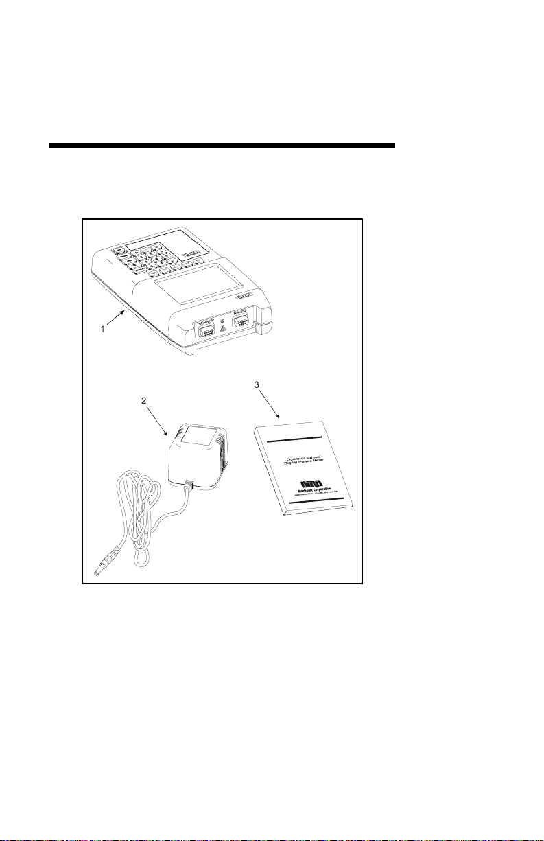
Items Supplied
Figure 1 Supplied Items
1. Bird Digital Power Meter (DPM)
2. AC Mains Adapter
3. Instruction Book
1
Page 16

Bird Model 5000 Digital Power Meter
8
Component Description
11
12
910
12
1
Model
5000
3
Digital Power Meter
Figure 2 Component Description
5
4
7
6
5
4
3
2
2
Page 17

Introduction
1. Speed Keys Activates the command displayed
above it.
2. On Key Turns the DPM on or off.
3. +/- Key Toggles between positive and
negative numbers.
4. Enter Key Completes data entry.
5. Escape Key Aborts data entry without accepting
changes.
6. Backlight Key Turns the backlight on momentarily.
7. Offset Key Enter offset values in dB.
8. Numeric Keys Input numeric values.
9. Sensor Port Connection for power sensors.
10. RS-232 Port Connection for an optional PC 9-pin
RS-232 (DB9) connector, compatible
with PC serial port. 9600 baud, 8
data bits, 1 stop bit, and no parity.
11. LCD Display Backlit liquid crystal display.
12. External DC
Connector
Connect either the ac adapter or the
cigarette lighter adapter. External
supplies power the unit and charge
the internal battery.
3
Page 18

Bird Model 5000 Digital Power Meter
011
Display Description
1
2
3
4
5
6
7
True Avg Power
MAX
Fwd
MIN
Match Eff% Rho VSWR dBr RL dBm W mW KW
Dpm
Rfl
Sens
Match Eff% Rho VSWR dBr RL dBm W mW KW
µ
µ
Overrange
Low Bat
8
Scale
Fwd
Units
Rfl
Units
Figure 3 Display Description
1. Field Indicator Indicates the type of power
being measured.
2. Major Display Displays forward power or
match efficiency, rho, VSWR, or
return loss.
3. Major Display
Annunciator
Indicates function being
measured.
4. Major Display Unit Unit of measure for the major
display.
5. Minor Display Displays reflected power or
match efficiency, rho, VSWR, or
return loss.
9
1
6. Minor Display
Annunciator
Indicates function being
measured.
7. Minor Display Unit Unit of measure for the minor
display.
4
Page 19

Introduction
8. Analog Bar Graph Proportional to the major
display. Minimum at 0 W or –20
dBm. Max at full scale power.
9. Overrange
Indicator
10. Low battery
Indicator
11. Menu Speed Key
Labels
Turns on when the forward
power exceeds 100% of scale or
the reflected power exceeds
120% of scale.
Turns on when the batteries
need charged. Refer to
“Charging Batteries” on
page 17.
Defines the function of the
speed keys.
Speed Keys
Scale — For element-based sensors, sets the forward
full scale power. This is listed on the forward element’s
nameplate. Reflected full scale power is automatically
set to 10 dB below the forward full scale. This speed
key is disabled for non-element-based sensors.
Fwd Units — Selects the units for the major display.
Rfl Units — Selects the units for the minor display.
This speed key is disabled for terminating sensors.
Recall Setup (Speed Key 4) — This speed key is only
enabled for the Directional Power Sensor, although
the label is never displayed. Enter a setup number to
load a stored setup. 0 returns to the default setups.
Setups are stored in the DPM using the optional
PCTool software. For more information, refer to the
help files in the PCTool Software.
5
Page 20

Bird Model 5000 Digital Power Meter
Indicators
Dashes — When no sensor is connected or if
communication with the sensor fails the display will
show a line of dashes and the bar scale will be blank.
Overrange Indicator — If the forward power exceeds
100% of full scale, “Overrange” will be displayed. If
forward or reflected power exceeds 120% of full scale,
the display will show a line of dashes and the bar scale
will be filled.
Low Battery Indicator — “Low Bat” is displayed when
the battery needs recharging. Refer to “Charging
Batteries” on page 17 for more information. The
display will change to “Bat Error” when a Terminating
Power Sensor is connected and the battery is very low.
Offset Indicator — “Fwd” will blink when an offset has
been applied.
Features
Compatibility — The DPM is compatible with Bird
Thruline or Terminating Power Sensors, and with
Bird VSWR Alarm and Broadcast Power Monitor
products with the use of an accessory adapter.
Serial Communication Link — Built-in serial port and
optional software let you download data to a personal
computer for analysis and storage.
Forward and Reflected Power at a Glance — Forward
and reflected power are easily read on the major and
minor display.
6
Page 21

Introduction
Optional Equipment
Directional Power Sensor (DPS) — Bird 5010,
requires two DPM Elements. As a Thruline Sensor,
the DPS measures both forward and reverse power,
enabling the DPM to display VSWR and other match
measurements. Includes interface cable.
Terminating Power Sensors (TPS)— Highly accurate
terminating sensors; do not require elements.
The Bird 5011 frequency range is 40 MHz – 4 GHz.
The 5011-EF frequency range is 40 MHz – 12 GHz.
Includes interface cable.
Automobile Cigarette Lighter Adapter —
(P/N 5A2238-1) Connects the DPM to a standard 12V
automotive cigarette lighter jack.
Soft Carry Case — (P/N 5000-030) Convenient and
protective. Cutouts allow for operation without
removal from the case.
Hard Carry Case — (P/N 5000-035) Protective case
holds DPM, sensor, and accessories.
Attenuators & Accessories — A variety of
attenuators and connectors for measuring large
powers with the TPS. For a complete list, see page 23.
7
Page 22

Bird Model 5000 Digital Power Meter
Interface Software — (P/N 4397A040) PC software
with real time display of DPM measurements. Can
also log data for analysis, printing, or storage.
System requirements: IBM PC or equivalent; Windows
95 or later, 2 MB free hard disk space; VGA monitor,
open Com port. Includes interface cable.
Serial to USB Adapter— (P/N DC-DB9-U) Converts
the serial cable to USB. Lets the DPM be connected to
a PC’s USB port if the serial port is unavailable.
8
Page 23

Chapter 2 Installation
Power Supply
The DPM uses a rechargeable Nickel-Metal Hydride
battery pack. Charge life is a minimum of 100 hours
continuous usage. “Low Bat” is displayed when the
batteries require charging.
NOTE: For optimum battery life, charge the
batteries only after “Low Bat” is displayed.
The DPM can use an external power source. Using the
DPM with the ac adapter or the 12V cigarette lighter
adapter will also charge the battery. Charging time
from full discharge is 8 hours using the ac adapter.
When using the cigarette lighter adapter, charge time
will depend on the car battery charge.
CAUTION
Use a Bird adapter only and do not use the adapter
with the batteries removed.
y AC Mains Adapter — To use the ac adapter. insert
the adapter’s barrel connector into the DPM’s
external dc connector (See Figure 2 on page 2).
Insert the adapter plug into a wall receptacle.
y Automobile Cigarette Lighter Adapter — Insert the
adapter’s barrel connector into the DPM’s external
dc connector. Insert the adapter plug into a
cigarette lighter jack.
9
Page 24

Bird Model 5000 Digital Power Meter
10
Figure 4 DPM Connections
Page 25

Installation
DPM Connection
CAUTION
Always turn off the DPM before connecting or
disconnecting a sensor.
Although unlikely, it is possible to corrupt the power
sensor firmware by connecting it to the DPM while the
DPM is on. To prevent this, always turn the DPM off
before connecting or disconnecting a sensor.
Connect the power sensor to the “Sensor” port on the
DPM using the sensor cable provided. If you are using
the optional PCTool software, connect the PC’s serial
port to the “RS-232” port on the DPM.
RF Connections
WARNING
Never attempt to connect or disconnect RF
equipment from the transmission line while RF
power is being applied.
Leaking RF energy is a potential health hazard.
Directional Power Sensor (DPS)
Connect the DPS to the RF line so that the arrow on
the DPS points towards the load. The element in the
forward socket should be inserted with its arrow
pointing in the direction of forward power, as shown
below. The reflected element should point in the
direction of reverse power. The forward element’s
power rating must be 10x the reverse element’s rating.
11
Page 26

Bird Model 5000 Digital Power Meter
Figure 5 DPS Element Orientation
Terminating Power Sensor (TPS)
CAUTION
Ground all instruments before connecting the
TPS(-EF). Electric shock could damage the sensor.
CAUTION
When connecting the TPS or the TPS-EF, only turn
the connector nut. Damage may occur if torque is
applied to the sensor body.
CAUTION
Do not exceed 2 W average or 125 W peak power for
5 µs when using the TPS or the TPS-EF.
Doing so will render the sensor inoperative.
RF connections are the same for the TPS-EF and the
TPS. In most cases, the TPS should be connected to an
attenuator or a directional coupler. For example, to
measure a transmitter with power output between 0.1
and 50 Watts, use a 40 dB, 50 Watt attenuator. Insert
the attenuator between the TPS and the RF source.
Only connect the TPS directly to the source if the RF
power will be less than 10 mW.
12
Page 27

Chapter 3 Operation
The Bird Digital Power Meter is very easy to operate.
Once a sensor is connected, turn the DPM on and take
a reading. Additional commands are available,
depending on the sensor used.
Normal Operation
y Connect the sensor.
y Turn on the DPM.
y Set the measurement units by pressing FWD Units
and RFL Units.
y If you know the system loss or are using an
attenuator, add the losses (in dB) of all components
in the system. For attenuators and other frequencydependent components, use the loss at the measured
frequency. Then, press OFFSET and enter the total
loss in dB. This will allow you to read the actual line
power. The DPM accepts offsets from 0 to 100 dB.
y Turn on the RF source.
y Read the power level on the display.
NOTE: The analog bar graph will respond immedi-
ately to changes in the RF power. The major and
minor displays will respond after a delay of 1 to 13
seconds, depending on the power level.
13
Page 28

Bird Model 5000 Digital Power Meter
Loading Setups
When used with the optional PCTool software, setups
can be stored in the DPM. Loading a setup will set the
forward scale (for the DPS only) and the offset (for
both the DPS and the TPS).
y Press Speed Key 4.
y Enter the number of the setup you want to load.
NOTE: Entering 0 returns the DPM to its default
scale and offset.
Directional Power Sensor
The Directional Power Sensor (DPS) uses Bird Plug-In
Elements. These are labeled with a max power and a
frequency range. The transmitter frequency should be
within the element range, and the forward element
power should be 10x the reverse element power.
Setting Forward Scale
For the DPS, the forward full scale power must be
entered manually. The reflected full scale power is
automatically set to 1/10 of the forward full scale.
y Press SCALE.
y Change the units with the FWD Units key until the
DPM units match the units on the forward element.
y Use the numeric keypad to enter the maximum
power of the element in the forward element socket.
NOTE: The element’s max power is listed on the
element nameplate.
y Press ENTER.
14
Page 29

Operation
Terminating Power Sensor
CAUTION
Do not exceed 2 W average or 125 W peak power for
5 µs when using the TPS or the TPS-EF.
Doing so will render the sensor inoperative.
Zeroing Sensor
Over time, the sensor’s “zero value” (reading with no
applied RF power) can drift, making all readings
inaccurate by this value. For example, if the zero value
is –2 µW, measuring a 5 mW signal will give a reading
of 4.998 mW, a 0.04% error. Measuring a 50 µW signal
will give a reading of 48 µW, a 4% error. If the drift
would be a significant error, rezero the sensor:
y Make sure the sensor has been connected to the
DPM and the DPM turned on for at least 5 minutes.
y Make sure no RF power is applied to the sensor.
y Press and hold 0 for at least three seconds. “CAL 0”
will be displayed and calibration will begin.
y Zeroing the sensor takes 60 seconds. The bar graph
will display calibration progress. When complete,
“0 CAL PASS” should be displayed. Press ENTER to
return to normal operation. If “0 CAL FAIL” is
displayed, make sure no RF power is applied to the
sensor, press ENTER and zero the sensor again.
TPS-EF
The Bird 5011-EF uses frequency correction factors to
provide more accurate measurements. To use these,
look at the label on the side of the sensor and find the
correction factor for the frequency being measured.
Add the correction factor to the other attenuation or
coupling factors and enter this as an offset.
15
Page 30

Bird Model 5000 Digital Power Meter
16
Page 31

Chapter 4 Maintenance
Cleaning
CAUTION
Harsh or abrasive detergents and some solvents
can damage the display unit and
information on the labels.
Clean the Bird Digital Power Meter and its display
with a soft cloth dampened with mild detergent and
water only. Clean sensors with a dry cleaning solvent
that leaves no residue.
Charging Batteries
Fully charged batteries provide a minimum of 100
hours of continuous operation. Charging time is
typically 8 hours using the ac adapter. The batteries
charge whenever the DPM is connected to either ac or
dc power sources, using either the ac Mains adapter or
the automobile cigarette lighter adapter. The unit will
charge with its power turned either on or off.
NOTE: For optimum battery life, charge the
batteries only after “Low Bat” is displayed.
17
Page 32

Bird Model 5000 Digital Power Meter
Troubleshooting
PROBLEM POSSIBLE
CAUSE
Nothing shown
on display
Display shows
dashes; bar
scale is blank
Display shows
“Bat Error”
or dashes and
“Low Bat”; bar
scale is blank
Unit is off Momentarily press the
Batteries are
drained
DPM firmware
corrupted
No sensor
connected
Sensor
communication
has failed
Sensor calibration corrupted
Batteries are
drained
REMEDY
ON key.
Use external power
source. (page 9)
Replace the batteries.
(page 20)
Update firmware.
Connect a sensor.
Use a different cable.
Use a different sensor.
Return sensor to Bird
for recalibration.
Turn off the DPM
before connecting or
disconnecting a sensor.
Use external power
source. (page 9)
Display shows
dashes and
“Overrange”;
bar scale is full
18
Unit is
overrange
Use higher power
elements (if applicable),
or reduce RF power.
Page 33

Maintenance
PROBLEM POSSIBLE
CAUSE
Erratic power
readings
Element
contact out of
alignment
(DPS)
Damaged
element (DPS)
Sensor has lost
its zero (TPS)
Sensor is
damaged
Sensor calibration corrupted
REMEDY
Align the contact. It
must be far enough out
to make good contact
with the element, but
must not restrict entry
of the element body.
Replace element.
Rezero sensor.
Replace sensor.
Return sensor to Bird
for recalibration.
Turn off the DPM
before connecting or
disconnecting a sensor.
19
Page 34

Bird Model 5000 Digital Power Meter
Battery Replacement
The Nickel-Metal Hydride (Ni-MH) batteries do not
normally need to be replaced. If necessary, however,
follow these instructions (see Figure 6).
WARNING
Disconnect from external power before any
disassembly. The potential for electric shock exists.
CAUTION
Replace only with Ni-MH rechargeable A batteries.
Nominal Voltage 1.2V; Capacity 2700mAhr.
20
Battery Connector
Figure 6 Back Cover Removal
Page 35

Maintenance
y Lay the DPM, display side down, on a clean surface.
y Use a small screwdriver to remove all six screws
from the back cover.
y Taking care to not disconnect the battery connector,
lift the back cover off, flip it over, and lay it, battery
side up, next to the front cover.
y Remove the old batteries.
y Install the new batteries checking the orientation of
the positive and negative terminals.
y Make sure the battery connector is connected.
y Taking care to not pinch the connector wires, put
the covers back together and screw into place.
Customer Service
Any maintenance or service procedure beyond the
scope of those in this chapter should be referred to a
qualified service center.
If you need to return the unit for any reason, contact
the Bird Service Center for a return authorization. All
instruments returned must be shipped prepaid and to
the attention of Bird Service Center.
Bird Service Center
30303 Aurora Road
Cleveland (Solon), Ohio 44139-2794
Phone: (440) 519-2298
Fax: (440) 519-2326
E-mail: bsc@bird-technologies.com
For the location of the Sales Office nearest you, give us
a call or visit our Web site at:
http://www.bird-electronic.com
21
Page 36

Bird Model 5000 Digital Power Meter
Parts List
Part Name Part Number
Digital Power Meter 5000
AC adapter
120V ac
230V ac
Cigarette Lighter Adapter 5A2238-1
Directional Power Sensor 5010
5A2229
5A2226
DPM Elements
See P/N 871-DPM-019-901,
the DPM Element Guide,
for a complete list of elements
Terminating Power Sensor
40 MHz – 4 GHz
40 MHz – 12 GHz
Soft Carry Case 5000-030
Hard Carry Case 5000-035
PC Interface Software 4397A040
Serial to USB Adapter DC-DB9-U
Instruction manual 920-5000S
Various
5011
5011-EF
22
Page 37

Maintenance
Attenuators & Accessories
N(F) – N(M) Attenuators (RF power range with TPS)
30 dB (10 mW – 10 W)
40 db (100 mW – 50 W)
DC Block 5011A035–1
N(F) – N(M) Test Cable, 1.5 m TC–MNFN–1.5–G
N(F) – N(M) Armored, Phase Stable Test Cable
1.5 m
3.0 m
Calibration Data 5011–CALDATA
Recommended for attenuators, test cables, dc block,
and right angle adapter
Adapters
8353A030–10
8353A040–50
TC–MNFN–1.5
TC–MNFN–3.0
N(F)–N(F) 4240-500-1 N(F) –N(M)
Right Angle
N(F)–SMA(F) 4240-500-4 N(F)–SMA(M) 4240-500-5
N(F)–7/16
DIN(F)
PA-FNFE N(F)–7/16
DIN(M)
4240-500-3
PA-FNME
23
Page 38

Bird Model 5000 Digital Power Meter
Specifications
Bird 5000 Digital Power Meter
Display Backlit LCD with major and
minor displays and analog bar
graph
Major Display 5 digits, 5/16” High
Minor Display 5 digits, 1/4” High
Analog Bar Graph 20 segment, horizontal
orientation. Tracks the major
digital display
Measurement Modes Average power, true average
power, or peak power as
determined by the element or
sensor.
Sensor Interface 9-pin D-shell RS-232 serial
connector. Sensor is powered from
the DPM.
PC Interface 9-pin RS-232 serial port
Dimensions 8.0”H x 4.625”W x 2.0”D
(203 x118 x 51 mm)
Weight 2 lbs. (0.9 kg) nominal
Power Supply Rechargeable Nickel-Metal
Hydride (NiMH) battery. Meter
may be operated from ac mains
using supplied adapter.
Battery Life 100 hours, minimum, per charge.
Battery Charge Time 8 hours for full charge.
Operating Temp. 32 to 122 ° F (0 to +50 °C)
24
Page 39

Maintenance
Storage Temp. –4 to 122 ° F (–20 to +50 °C)
Humidity 95% ± 5% max. (non-condensing)
Altitude 15,000 ft. (4572 m) operating
EMC Complies with directive 92/31/
EEC with exceptions noted:
Emissions: EN-55011:1991,
Class B
EN-61000-3-2:1995
EN-61000-3-3:1995
Immunity: EN-50082-2:1997
Safety Complies with EN-61010, IAW
Council Directives 73/23/EEC and
93/68/EEC
Mechanical Shock MIL-T-28800D Class 3
Vibration MIL-T-28800D Class 3
25
Page 40

Bird Model 5000 Digital Power Meter
Bird 5010 Sensor
Sensor Type /
Elements
*
Bird Thruline directional dualelement line section. Uses two
Bird DPM Elements.
†
Power
Frequency Range
0.1 to 1,000 W
†
2 MHz to 3600 MHz
Accuracy With DPM Elements:
±5% of reading 15 to 35 °C RSS
±7% of reading –10 to 50 °C RSS
Peak / Average 10 dB maximum with DPM
Elements.
Settling Time < 2.5 seconds
Connectors QC Type, Female N normally
supplied
Insertion VSWR 1.05:1 up to 1 GHz (with N
connectors).
Dimensions 2.5”H x 5.0”W x 2.0”D
(58 x 127 x 51 mm)
Weight 1.25 lb. (0.57 kg) nominal with
elements.
* RFL element power must be 1/10 of FWD power.
† Power and frequency range based on selected elements.
26
Page 41

Maintenance
Bird 5011 and 5011-EF Sensors
Sensor Type Diode based terminated true
average power measurement
Power
Maximum Power 2 W avg.
Frequency Range
5011
5011-EF
Accuracy ±(5% of reading
Peak / Average 12 dB max
Input Connector
5011
5011-EF
Output Connector Male DB-9 to host instrument
Input Impedance 50 Ohms (nominal)
Input VSWR:
5011
Typical
Maximum
5011-EF
Typical
Maximum
10
µW to 10 mW
(–20 dBm to +10 dBm)
125 W peak for 5 µs
40 MHz to 4 GHz
40 MHz to 12 GHz
*
+ 1.0 µW)
(excluding mismatch uncertainty)
(with correction factors for
5011-EF)
N Male
Precision N Male
1.03 (36.6 dB return loss)
1.20 (20.8 dB return loss)
1.05 (32.0 dB return loss)
1.25 (19.1 dB return loss)
27
Page 42

Bird Model 5000 Digital Power Meter
Power Supply From host instrument via cable
connection
Operating Temp. –10 to +50 °C (+14 to +122 °F)
Storage Temp. –40 to +80 °C (–40 to +176 °F)
Humidity 95% max. (non-condensing)
Altitude 15,000 ft operating
Size 6” long max . (including
connectors) 1.5” diameter nominal
Weight 3/4 lb. (0.35 kg) max.
Recommended Cali-
12 Months
bration Interval
* 5011: Above 40 °C, when making measurements at
frequencies between 40 and 100 MHz, add 1%.
5011-EF: Above 40 °C or below 10 °C, add 1%.
28
Page 43

Limited Warranty
All products manufactured by Seller are warranted to be free from
defects in material and workmanship for a period of one (1) year,
unless otherwise specified, from date of shipment and to conform to
applicable specifications, drawings, blueprints and/or samples.
Seller’s sole obligation under these warranties shall be to issue credit,
repair or replace any item or part thereof which is proved to be other
than as warranted; no allowance shall be made for any labor charges
of Buyer for replacement of parts, adjustment or repairs, or any other
work, unless such charges are authorized in advance by Seller.
If Seller’s products are claimed to be defective in material or
workmanship or not to conform to specifications, drawings,
blueprints and/or samples, Seller shall, upon prompt notice thereof,
either examine the products where they are located or issue shipping
instructions for return to Seller (transportation charges prepaid by
Buyer). In the event any of our products are proved to be other than
as warranted, transportation costs (cheapest way) to and from
Seller’s plant, will be borne by Seller and reimbursement or credit
will be made for amounts so expended by Buyer. Every such claim for
breach of these warranties shall be deemed to be waived by Buyer
unless made in writing within ten (10) days from the date of
discovery of the defect.
The above warranties shall not extend to any products or parts
thereof which have been subjected to any misuse or neglect, damaged
by accident, rendered defective by reason of improper installation or
by the performance of repairs or alterations outside of our plant, and
shall not apply to any goods or parts thereof furnished by Buyer or
acquired from others at Buyer’s request and/or to Buyer’s
specifications. Routine (regularly required) calibration is not covered
under this limited warranty. In addition, Seller’s warranties do not
extend to the failure of tubes, transistors, fuses and batteries, or to
other equipment and parts manufactured by others except to the
extent of the original manufacturer’s warranty to Seller.
The obligations under the foregoing warranties are limited to the
precise terms thereof. These warranties provide exclusive remedies,
expressly in lieu of all other remedies including claims for special or
consequential damages. SELLER NEITHER MAKES NOR
ASSUMES ANY OTHER WARRANTY WHATSOEVER, WHETHER
EXPRESS, STATUTORY, OR IMPLIED, INCLUDING
WARRANTIES OF MERCHANTABILITY AND FITNESS, AND NO
PERSON IS AUTHORIZED TO ASSUME FOR SELLER ANY
OBLIGATION OR LIABILITY NOT STRICTLY IN ACCORDANCE
WITH THE FOREGOING.
Page 44

DECLARATION OF CONFORMITY
Manufacturer: Bird Electronic Corporation
30303 Aurora Road
Cleveland, Ohio 44139-2794
Product: Digital Power Meter and Power Sensor
Models: 5000 5010
The undersigned hereby declares, on behalf of Bird
Electronic Corporation of Cleveland, Ohio, that the abovereferenced product, to which this declaration relates, is in
conformity with the provisions of the following standards
with exceptions noted;
European Standard EN 55011:1991 - Emissions: Class B
•
• European Standard EN 61000-3-2:1995 - Emissions
• European Standard EN 61000-3-3:1995 - Emissions
• European Standard EN 50082-2:1997 - Immunity
These standards are in accordance with Council Directive
89/336/EEC, on Electromagnetic Compatibility, as amended
by Council Directive 92/31/EEC.
• European Standard EN 61010-1:1993 - Safety, Group II
Including Amendment 2: 1995
This standard is in accordance with Council Directive 73/23/
EEC and 93/68/EEC.
The technical documentation file required by this directive is
maintained at the corporate headquarters of Bird Electronic
Corporation, 30303 Aurora Road, Cleveland, Ohio 44139.
Bob Gardiner
Director of Quality
Bird Electronic Corporation
Page 45

DECLARATION OF CONFORMITY
Manufacturer: Bird Electronic Corporation
30303 Aurora Road
Cleveland, Ohio 44139-2794
Product: Terminating Power Sensor
Models: 5011
The undersigned hereby declares, on behalf of Bird
Electronic Corporation of Cleveland, Ohio, that the abovereferenced product, to which this declaration relates, is in
conformity with the provisions of the following standards
with exceptions noted;
European Standard EN 55011:1998 - Radiated Emissions
•
• European Standard EN 61000-4-2:1995 - ESD Immunity
• European Standard EN 61000-4-3:1995 - Radiated RF /
EMF Immunity
• European Standard EN 61000-4-4:1995 - Fast Transient /
Burst Immunity
• European Standard EN 61000-4-6:1995 - Conducted
Immunity
These standards are in accordance with EMC Directive (89/
336/EEC). Electrical equipment for measurement, control
and laboratory use, EN 61326-1, 1997 edition.
European Standard EN 61010-1:1993 - Part 1: General
•
Requirements Including Amendment 2: 1995
This standard is in accordance with Low Voltage Directive
(73/23/EEC), 1973
The technical documentation file required by this directive is
maintained at the corporate headquarters of Bird Electronic
Corporation, 30303 Aurora Road, Cleveland, Ohio 44139.
Bob Gardiner
Director of Quality
Bird Electronic Corporation
Page 46

DECLARATION OF CONFORMITY
Manufacturer: Bird Electronic Corporation
30303 Aurora Road
Cleveland, Ohio 44139-2794
Product: Terminating Power Sensor
Models: 5011-EF
The undersigned hereby declares, on behalf of Bird
Electronic Corporation of Cleveland, Ohio, that the above
referenced product, to which this declaration relates, is in
conformity with the provisions of the following standards;
European Standard EN 61326-1:1997 - Electronic
•
Equipment for Measurement, Control and Laboratory Use EMC Requirements
• European Standard EN 55011:1998 - Radiated Emissions
• European Standard EN 61000-4-2:1995 - ESD Immunity
• European Standard EN 61000-4-3:1995 - Radiated RF /
EMF Immunity
• European Standard EN 61000-4-4:1995 - Fast Transient /
Burst Immunity
• European Standard EN 61000-4-6:1995 - Conducted
Immunity
These standards are in accordance with EMC Directive (89/
336/EEC).
• European Standard EN 61010-1:1993 - Part 1: General
Requirements Including Amendment 2: 1995
This standard is in accordance with Low Voltage Directive
(73/23/EEC), 1973
The technical documentation supporting compliance with
these directives is maintained at Bird Electronic
Corporation, 30303 Aurora Road, Cleveland, Ohio 44139.
Bob Gardiner
Director of Quality
Bird Electronic Corporation
Page 47

Page 48

QUALITY INSTRUMENTS
FOR RF POWER MEASUREMENTS
From 2 to 4000 MHz and from 25 milliwatts
to 250 kilowatts in 50 ohm coaxial line systems
TERMALINE
ABSORPTION
WATTMETERS
LOAD RESISTORS
CALORIMETERS
THRULINE
DIRECTIONAL
MONITORING
WATTMETERS
TENULINE
ATTENUATORS
COAXWITCH
SELECTOR
SWITCHES
COAXIAL RF FILTERS
®
®
®
®
SENTRILINE
FILTER-COUPLERS
ELECTRONIC CORPORATION
30303 Aurora Road Cleveland, (Solon) Ohio 44139-2794
®
 Loading...