

Page 1
Electronic Corporation
30303 Aurora Road Cleveland (Solon), Ohio 44139-2794
Phone: (216)248-1200 Fax: (216)248-5426
This data sheet is used to document
components not documented
elsewhere.
Power Meter documentation is
included in a separate manual
with parts differences noted
within this sheet.
Refer to the following pages for
specifications and system block diagram.
Power Meter Model 4421-110
Data Sheet
MODEL 4421 RF Power Meter
AUTO
RANGE
UP
DOWN
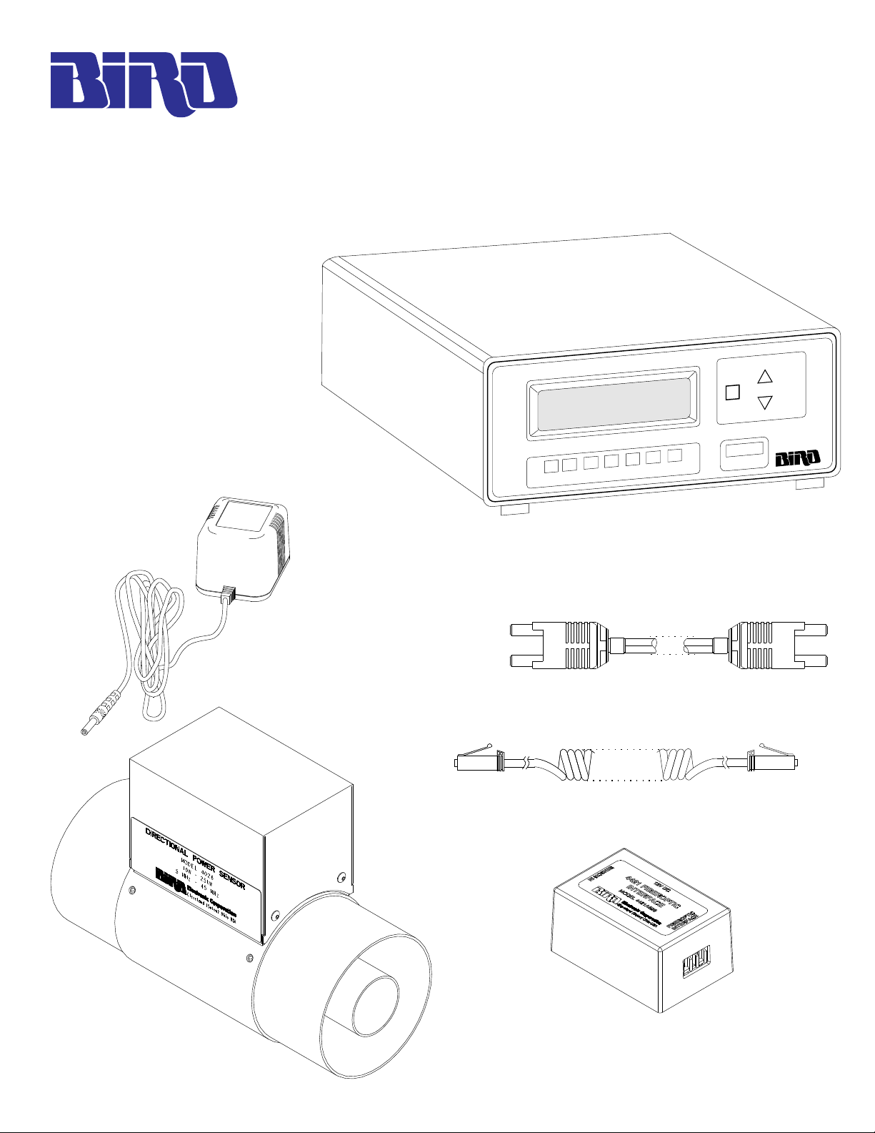
Note: These components are shipped in various
packages.
AC Mains Adapter
MIN
SWR
RFL
FWD
Power Meter
Fiberoptic Cable
Sensor Cable
MAX
LIGHT
dBm
ON / OFF
Sensor
Fiberoptic Interface
Page 2

Power Meter Model 4421-110
RF Power Meter Parts List Changes
Parts listed in the Model 4421 Operating Instructions for the Model 4421-107 are the same as the Model
4421-110 with the following exceptions:
PC Board, Main Control, Assembly p/n 6085A012
EPROM p/n 4421-052
Panel, Rear Assembly p/n 6085-008
Power Sensor Model 4026 Specifications
Type: Thruline® Design for direct insertion in 50 ohm line
Circuitry: Microprocessor-based measurement and conversion
Power Input Range: 10W - 25kW (30kW maximum)
Frequency Range: 5MHz to 45MHz
VSWR Range: 1.00 to - 2.00 (40.0 to 9.5dB return loss)
Accuracy:
Impedance: 50 ohms nominal
Insertion VSWR: 1.05 maximum (32.3dB return loss)
Insertion Loss: <0.05dB
Minimum Directivity: 30dB
Sampling Rate: Approximately 2 readings / second
Calibration: Calibration vs. frequency curve stored in non-volatile memory
Temperature Range:
Connectors: 3-1/8" unflanged
Electrical Length: 7.5" (190.5mm)
Weight: 4 lb. 8 oz. (2kg)
Power: Supplied via sensor cable
1
FWD: ±3% of reading
RFL: ±3% of reading ±
VSWR: Power measurement dependent
2
3
4
FWD PWR
1000
within each sensor. Sensor output corrected at a frequency of
measurement within rated range.
Operating: Temperature compensated for rated accuracy
from 0° to 50°C (32° to 122°F)
Storage: -20° to 70°C (-4° to 158°F)
1
For rated accuracy, no more than 1% AM harmonics -50dBc or less, terminating VSWR 2:1 or less.
2
Forward power is defined as power traveling from the source to the load. Measurement accuracy
is referenced to the load connector.
3
Reflected power is defined as power traveling from the load to the source. Measurement accuracy
is referenced to the source connector.
4
Calculated from forward and reflected power.
Page 2
Page 3

Power Meter Model 4421-110
System Block Diagram
Refer to safety information in the model 4421 operating instructions prior to installation.
Transmitted traveling waves should always be applied to source input of power sensor.
Applying travelling waves to load port will result in erroneous display.
50 OHM 50 OHM
Power Sensor
Signal Source
Sensor Cable
Sensor IN
Fiberoptic
Interface
Fiberoptic
Interface
12V DC
50 OHM Termination
AC Mains
Adapter
220Vac
Fiberoptic Cable
Power
Sensor
Power Meter
Page 3
 Loading...