

Page 1

MULTI-PURPOSE
THRULINE
RF POWER ANALYST
®
WATTMETER
®
MODEL 4391A
CABLE AND ANTENNA TESTER
FOR WIRELESS SYSTEMS
OPERATING INSTRUCTIONS
©Copyright 2012
Instruction Book Part Number 920-4391A Rev. K
Thruline® and Power Analyst® are Registered Trademark of
by Bird Electronic Corporation
Bird Electronic Corporation
Page 2

Safety Precautions
The following are general safety precautions that are not necessarily related to
any specific part or procedure, and do not necessarily appear elsewhere in this
publication. These precautions must be thoroughly understood and apply to all
phases of operation and maintenance.
WARNING
Keep Away From Live Circuits
Operating Personnel must at all times observe general safety precautions. Do
not replace components or make adjustments to the inside of the test
equipment with the high voltage supply turned on. To avoid casualties, always
remove power.
WARNING
Shock Hazard
Do not attempt to remove the RF transmission line while RF power is present.
WARNING
Do Not Service Or Adjust Alone
Under no circumstances should any person reach into an enclosure for the
purpose of service or adjustment of equipment except in the presence of
someone who is capable of rendering aid.
WARNING
Safety Earth Ground
An uniterruptible earth safety ground must be supplied from the main power
source to test instruments. Grounding one conductor of a two conductor
power cable is not sufficient protection. Serious injury or death can occur if this
grounding is not properly supplied.
WARNING
Resuscitation
Personnel working with or near high voltages should be familiar with modern
methods of resuscitation.
WARNING
Remove Power
Observe general safety precautions. Do not open the instrument with the
power on.
16
Page 3
Safety Symbols
WARNING
Warning notes call attention to a procedure, which if not correctly performed,
could result in personal injury.
CAUTION
Caution notes call attention to a procedure, which if not correctly performed,
could result in damage to the instrument.
The caution symbol appears on the equipment indicating there is
important information in the instruction manual regarding that particular area
Note: Calls attention to supplemental information.
Warning Statements
The following safety warnings appear in the text where there is danger to operating and maintenance personnel, and are repeated here for emphasis.
Use only Nickel Metal Hydride (NiMH) batteries that have a minimum
WARNING
capacity of 4500 milliamper hours (mAh). Do not install batteries that are
not Nickel Metal Hydride. Do not install NiMH batteries that have less than
4500 mAh capacity. Failure to comply may result in damage to the batteries,
damage to the instrument, and injury to personnel from battery chemicals.
On pages 16 and 18.
WARNING
Use dry cleaning solvents in a well ventilated area. Avoid excessive inhalation
of solvent fumes, since they can be toxic in heavy concentrations. Always wear
eye protection and avoid skin contact with the solvent.
On pages 17.
WAR NIN G
Ensure that the power cable is unplugged before opening the wattmeter case. The
power supply capacitor, C1, can retain a dangerous charge that must be removed
before touching. Always have another person standing by who is trained in electric
shock first aid.
On pages 22.
i
Page 4

Caution Statements
The following equipment cautions appear in the text and are repeated here for
emphasis.
Long-term storage of this instrument can affect battery performance and reduce
battery life. Do not store the instrument for long periods of time without
recharging the batteries (refer to page 18). Failure to comply may result in reduced
battery charge and shortened battery life.
On pages 7 and 16.
Always be certain the 115/230 voltage selector is set to the proper voltage
before AC power is applied.
On page 7.
Never apply RF power to the Model 4391A Wattmeter unless both line section
sockets are filled with either an element or a dust plug. If an element is used it is
advisable to place the element with the arrow at a 90° angle to the coaxial line.
On page 9.
Always disconnect AC power before opening the Model 4391 enclosure.
Removal of at least one battery cell is also recommended when servicing the
On page 9.
If the element cannot be fully inserted into the socket, do not force it. You
might damage the element.
CAUTION
CAUTION
CAUTION
CAUTION
instrument.
CAUTION
On page 20.
CAUTION
This instrument contains static sensitive electronic components. Before
opening or servicing the unit, make sure that you understand and practice
electrostatic discharge component handling. Failure to comply may result in
permanent damage to sensitive components.
On page 22.
ii
Page 5

Safety Statements
USAGE
ANY USE OF THIS INSTRUMENT IN A MANNER NOT
SPECIFIED BY THE MANUFACTURER MAY IMPAIR THE
INSTRUMENT’S SAFETY PROTECTION.
USO
EL USO DE ESTE INSTRUMENTO DE MANERA NO
ESPECIFICADA POR EL FABRICANTE, PUEDE ANULAR LA
PROTECCIÓN DE SEGURIDAD DEL INSTRUMENTO.
BENUTZUNG
WIRD DAS GERÄT AUF ANDERE WEISE VERWENDET ALS VOM
HERSTELLER BESCHRIEBEN, KANN DIE GERÄTESICHERHEIT
BEEINTRÄCHTIGT WERDEN.
UTILISATION
TOUTE UTILISATION DE CET INSTRUMENT QUI N’EST PAS
EXPLICITEMENT PRÉVUE PAR LE FABRICANT PEUT
ENDOMMAGER LE DISPOSITIF DE PROTECTION DE
L’INSTRUMENT.
IMPIEGO
QUALORA QUESTO STRUMENTO VENISSE UTILIZZATO IN
MODO DIVERSO DA COME SPECIFICATO DAL PRODUTTORE
LA PROZIONE DI SICUREZZA POTREBBE VENIRNE
COMPROMESSA.
iii
Page 6

SERVICE
SERVICING INSTRUCTIONS ARE FOR USE BY SERVICE TRAINED PERSONNEL ONLY. TO AVOID DANGEROUS
ELECTRIC SHOCK, DO NOT PERFORM ANY SERVICING
UNLESS QUALIFIED TO DO SO.
SERVICIO
LAS INSTRUCCIONES DE SERVICIO SON PARA USO
EXCLUSIVO DEL PERSONAL DE SERVICIO CAPACITADO. PARA
EVITAR EL PELIGRO DE DESCARGAS ELÉCTRICAS, NO
REALICE NINGÚN SERVICIO A MENOS QUE ESTÉ
CAPACITADO PARA HACERIO.
WARTUNG
ANWEISUNGEN FÜR DIE WARTUNG DES GERÄTES GELTEN
NUR FÜR GESCHULTES FACHPERSONAL.
ZUR VERMEIDUNG GEFÄHRLICHE, ELEKTRISCHE SCHOCKS,
SIND WARTUNGSARBEITEN AUSSCHLIEßLICH VON
QUALIFIZIERTEM SERVICEPERSONAL DURCHZUFÜHREN.
ENTRENTIEN
L’EMPLOI DES INSTRUCTIONS D’ENTRETIEN DOIT ÊTRE
RÉSERVÉ AU PERSONNEL FORMÉ AUX OPÉRATIONS
D’ENTRETIEN. POUR PRÉVENIR UN CHOC ÉLECTRIQUE
DANGEREUX, NE PAS EFFECTUER D’ENTRETIEN SI L’ON N’A
PAS ÉTÉ QUALIFIÉ POUR CE FAIRE.
ASSISTENZA TECNICA
LE ISTRUZIONI RELATIVE ALL’ASSISTENZA SONO PREVISTE
ESCLUSIVAMENTE PER IL PERSONALE OPPORTUNAMENTE
ADDESTRATO. PER EVITARE PERICOLOSE SCOSSE
ELETTRICHE NON EFFETTUARRE ALCUNA RIPARAZIONE A
MENO CHE QUALIFICATI A FARLA.
iv
Page 7

UNITS ARE EQUIPPED WITH RECHAREABLE BATTERIES.
THESE ARE TO BE REPLACED BY AUTHORIZED SERVICE
PERSONNEL ONLY!!!
LAS UNIDADES VIENEN EQUIPADAS CON BATERIAS
RECARGABLES.
¡¡¡Y SOLAMENTE EL PERSONAL DE SERVICIO AUTORIZADO
PUEDE REEMPLAZARLAS!!!
GERÄTE SIND MIT WIEDER AUFLADBAREN BATTERIEN
BESTÜCKT.
BATTERIEN SIND NUR VON QUALIFIZIERTEM SERICE
PERSONAL AUSZUWECHSELN!!!
CES DISPOSITIFS SONT ÉQUIPÉS DE BATTERIES
RECHARGEABLES.
SEUL LE PERSONNEL D’ENTRETIEN AUTORISÉ EST HABILITÉ
À LES REMPLACER !
LE UNITÀ SONO DOTATE DI BATTERIE RICARICABILI,
CHE DEVONO DA COME SPECIFICATO DAL PRODUTTORE LA
PROTEZIONE DI SICUREZZA POTREBBE VENIRNE
COMPROMESSA.
USE CORRECT VOLTAGE SETTING AND FUSE - SEE MANUAL.
UTILISER UNE TENSION ET UN FUSIBLE CORRECTS - CONSULTER
LE MODE D'EMPLOI.
USE LA INSTALACION Y FUSIBLE DE VOLTAJE CORRECTO - VEA
EL MANUAL.
AUSSCHLIESSLICH VORSCHRIFTSMÄSSIGE
WECHSELSPANNUNGS-EINSTELLUNG UND SICHERUNG
BENUTZEN - SIEHE DAZU HANDBUCH.
UTILLIZZARE TENSIONE E FUSIBLE ADATTI - FARE RIFERIMENTO
AL MANUALE.
v
Page 8

BE SURE THE 115/230V AC VOLTAGE SELECTOR IS SET TO THE
PROPER LINE VOLTAGE, AND THE CORRECT AC LINE FUSE IS
INSTALLED BEFORE AC POWER IS APPLIED.
S'ASSURER QUE LE SÉLECTEUR DE TENSION 115/230V C.A. EST
BIEN RÉGLÉ POUR LA TENSION DU RÉSEAU ET QUE LE FUSIBLE
DE LIGNE C.A. CORRECT EST EN PLACE AVANT DE METTRE SOUS
TENSION C.A.
CERCIORESE QUE EL SELECTOR DE VOLTAJE DE 115/230V CA
ESTE COLOCADO A LA LINEA DE VOLTAJE APROPIADA Y QUE EL
FUSIBLE ESTE INSTALADO A LA LINEA CA ANTES DE APLICAR LA
CORRIENTE ALTERNA.
VOR EINSCHALTEN DER WECHSELSTROMZUFUHR
SICHERSTELLEN, DASS DER 115/230V WECHSELSPANNUNGSSELEKTOR AUF DIE VORSCHRIFTSMÄSSIGE
LEITUNGSSPANNUNG EINGESTELLT UND DIE RICHTIGE
WECHSELSTROM-HAUPTSICHERUNG EINGESETZT IST.
PRIMA DI EROGARE CORRENTE, ASSICURARSI CHE IL
SELETTORE DI VOLTAGGIO 115/230 V.C.A. SIA REGOLATO
CORRETTAMENTE E CHE IL FUSIBLE ADATTO ALLA LINEA DI
ALIMENTAZIONE C.A. SIA INSTALLATO.
vi
Page 9

RF VOLTAGE MAY BE PRESENT IN RF ELEMENT SOCKET - KEEP
ELEMENT IN SOCKET DURING OPERATION.
DE LA TENSION H.F. PEAT ÊTRE PRÉSENTE DANS LA PRISE DE
L'ÉLÉMENT H.F. - CONSERVER L'ÉLÉMENT DANS LA PRISE LORS
DE L'EMPLOI.
HF-SPANNUNG KANN IN DER HF-ELEMENT-BUCHSE ANSTEHEN ELEMENT WÄHREND DES BETRIEBS EINGESTÖPSELT LASSEN.
PUEDE HABER VOLTAJE RF EN EL ENCHUFE DEL ELEMENTO RF MANTENGA EL ELEMENTO EN EL ENCHUFE DURANTE LA
OPERACION.
IL PORTAELEMENTO RF PUÒ PRESENTARE VOLTAGGIO RF TENERE L'ELEMENTO NELLA PRESA DURANTE IL
FUNZIONAMENTO.
vii
Page 10

About This Manual
This manual covers the operating and maintenance instructions for the following models:
4391A
Changes to this Manual
We have made every effort to ensure this manual is accurate. If you discover any
errors, or if you have suggestions for improving this manual, please send your
comments to our Solon, Ohio factory. This manual may be periodically updated.
When inquiring about updates to this manual refer to the part number and revision on the title page.
Chapter Layout
Introduction - Introduces the external features and and functions of the unit,
equipment provided, and optons available.
Theory of Operation - Describes the overall operation of the circuitry and the
instrument functions.
Installation - Provides information about connecting the instrument to your
equipment.
Operation - All instructions necessary to operate the equipment, are con-
tained in this section.
Maintenance - If a failure should occur, the troubleshooting section will aid in
isolating and repairing the failure.
Parts - For location of major assemblies or parts refer to the part lists and asso-
ciated drawings.
viii
Page 11

Table of Contents
Safety Precautions . . . . . . . . . . . . . . . . . . . . . . . . . . . . . . . . . . . . . . . . . 0
Safety Symbols . . . . . . . . . . . . . . . . . . . . . . . . . . . . . . . . . . . . . . . . . . . . . . . . . . . i
Warning Statements . . . . . . . . . . . . . . . . . . . . . . . . . . . . . . . . . . . . . . . . . . . . . . i
Caution Statements . . . . . . . . . . . . . . . . . . . . . . . . . . . . . . . . . . . . . . . . . . . . . . ii
Safety Statements . . . . . . . . . . . . . . . . . . . . . . . . . . . . . . . . . . . . . . . . . . . . . . . iii
About This Manual . . . . . . . . . . . . . . . . . . . . . . . . . . . . . . . . . . . . . . . viii
Changes to this Manual . . . . . . . . . . . . . . . . . . . . . . . . . . . . . . . . . . . . . . . . . . viii
Chapter Layout . . . . . . . . . . . . . . . . . . . . . . . . . . . . . . . . . . . . . . . . . . . . viii
Chapter 1 Introduction . . . . . . . . . . . . . . . . . . . . . . . . . . . . . . . . . . . . . 1
Purpose and Function . . . . . . . . . . . . . . . . . . . . . . . . . . . . . . . . . . . . . . . . . . . . 1
Description . . . . . . . . . . . . . . . . . . . . . . . . . . . . . . . . . . . . . . . . . . . . . . . . . . . . . 2
Chapter 2 Theory of Operation. . . . . . . . . . . . . . . . . . . . . . . . . . . . . . . 3
Description of Operation . . . . . . . . . . . . . . . . . . . . . . . . . . . . . . . . . . . . . . . . . 3
Keyboard, Range Switches, and Display Group . . . . . . . . . . . . . . . . . . . . . 3
Elements, Analog Circuitry, and A/D Converter . . . . . . . . . . . . . . . . . . . . 4
Chapter 3 Installation . . . . . . . . . . . . . . . . . . . . . . . . . . . . . . . . . . . . . . 7
Operating on AC Power . . . . . . . . . . . . . . . . . . . . . . . . . . . . . . . . . . . . . . . . . . . 7
Connections . . . . . . . . . . . . . . . . . . . . . . . . . . . . . . . . . . . . . . . . . . . . . . . . . . . . 8
Chapter 4 Operating Instructions . . . . . . . . . . . . . . . . . . . . . . . . . . . . 9
Operating Modes . . . . . . . . . . . . . . . . . . . . . . . . . . . . . . . . . . . . . . . . . . . . . . . . 9
Reading Forward CW Power . . . . . . . . . . . . . . . . . . . . . . . . . . . . . . . . . . . . 9
Reading Reflected CW Power . . . . . . . . . . . . . . . . . . . . . . . . . . . . . . . . . . 10
Reading SWR . . . . . . . . . . . . . . . . . . . . . . . . . . . . . . . . . . . . . . . . . . . . . . . 10
Measuring Peak Envelope Power . . . . . . . . . . . . . . . . . . . . . . . . . . . . . . . 11
Measuring Amplitude Modulation . . . . . . . . . . . . . . . . . . . . . . . . . . . . . . 12
Measuring Power in dBm . . . . . . . . . . . . . . . . . . . . . . . . . . . . . . . . . . . . . 13
Measuring Return Loss . . . . . . . . . . . . . . . . . . . . . . . . . . . . . . . . . . . . . . . 13
Insertion Loss or Attenuation . . . . . . . . . . . . . . . . . . . . . . . . . . . . . . . . . . . . . 14
Monitoring Maximum and Minimum Readings . . . . . . . . . . . . . . . . . . . 14
Using the Peaking Aid . . . . . . . . . . . . . . . . . . . . . . . . . . . . . . . . . . . . . . . . 15
Battery Care . . . . . . . . . . . . . . . . . . . . . . . . . . . . . . . . . . . . . . . . . . . . . . . . . . . 15
ix
Page 12

Chapter 5 Maintenance . . . . . . . . . . . . . . . . . . . . . . . . . . . . . . . . . . . . 17
Preventive Maintenance . . . . . . . . . . . . . . . . . . . . . . . . . . . . . . . . . . . . . . . . . 17
Cleaning and Inspection . . . . . . . . . . . . . . . . . . . . . . . . . . . . . . . . . . . . . . . . . 17
Long-term Storage . . . . . . . . . . . . . . . . . . . . . . . . . . . . . . . . . . . . . . . . . . . . . . 18
Calibration . . . . . . . . . . . . . . . . . . . . . . . . . . . . . . . . . . . . . . . . . . . . . . . . . . . . 18
Required Equipment . . . . . . . . . . . . . . . . . . . . . . . . . . . . . . . . . . . . . . . . . 18
Initial Setup . . . . . . . . . . . . . . . . . . . . . . . . . . . . . . . . . . . . . . . . . . . . . . . . 19
Element Wiper Contact Adjustment . . . . . . . . . . . . . . . . . . . . . . . . . . . . . . . 20
Troubleshooting . . . . . . . . . . . . . . . . . . . . . . . . . . . . . . . . . . . . . . . . . . . . . . . . 21
General . . . . . . . . . . . . . . . . . . . . . . . . . . . . . . . . . . . . . . . . . . . . . . . . . . . . 21
Disassembly . . . . . . . . . . . . . . . . . . . . . . . . . . . . . . . . . . . . . . . . . . . . . . . . . . . 22
Front Panel Removal . . . . . . . . . . . . . . . . . . . . . . . . . . . . . . . . . . . . . . . . . 23
Main Printed Circuit (PC) Board Removal . . . . . . . . . . . . . . . . . . . . . . . . 23
QC Connectors Removal . . . . . . . . . . . . . . . . . . . . . . . . . . . . . . . . . . . . . . 24
Line Section Removal . . . . . . . . . . . . . . . . . . . . . . . . . . . . . . . . . . . . . . . . 24
Battery Replacement . . . . . . . . . . . . . . . . . . . . . . . . . . . . . . . . . . . . . . . . . 26
Parts List . . . . . . . . . . . . . . . . . . . . . . . . . . . . . . . . . . . . . . . . . . . . . . . . . . . . . . 28
Customer Service . . . . . . . . . . . . . . . . . . . . . . . . . . . . . . . . . . . . . . . . . . . . . . . 31
Specifications . . . . . . . . . . . . . . . . . . . . . . . . . . . . . . . . . . . . . . . . . . . . . . . . . . 32
Limited Warranty . . . . . . . . . . . . . . . . . . . . . . . . . . . . . . . . . . . . . . . . . 34
x
Page 13

Chapter 1 Introduction
The Model 4391A is a multi-purpose Radio Frequency wattmeter designed around
a microcomputer. A program stored in permanent memory controls the operation
of the instrument at all times, permitting the detection and correction of various
error sources and the refinement of the raw data produced by the directional
detectors. The instrument can compute VSWR, amplitude modulation, and various decibel variables reducing the odds of error and making such measurements
consistent or repeatable regardless of who makes the measurement.
Other benefits include extended range using standard elements in some modes
of operation, continuous monitoring of maximum and minimum readings, a
peaking aid, and error messages.
Because of its complexity, the proper use of the 4391A is not always obvious. For
this reason it is strongly advised that this manual be read in its entirety before
using the device.
Purpose and Function
The 4391A RF Power Analyst is an insertion type digital RF Directional Thruline®
Wattmeter designed to measure peak or average power flow, load match, and
amplitude modulation in 50 ohm coaxial transmission lines. It is intended for use
with CW, AM, FM, SSB, TV, and Pulse modulation envelopes. The instrument
directly reads PEP or CW power in watts, milliwatts, or kilowatts in 9 ranges from
2.5 to 1000 full scale forward power and 0.25 to 100 full scale reflected power
depending on the Plug-in Element. In addition it reads SWR directly over the
range of 1.00 to 99.99, percent modulation directly over the range of 0.0 to 99.9,
and return loss over the range of 0 to 36.1 dB. For convenience, forward and
reflected CW power can be displayed in dBm (dB above 1 milliwatt) from 6 dB
above to 24 dB below nominal element range.
Power range and frequency band are determined by the Plug-in Elements used.
Two switches on the front panel of the instrument are set by the user to correspond to the nominal power range of the forward element. The reflected element
is assumed to have a nominal range one tenth that of the forward element.
In any mode of operation, the instrument can recall from memory the lowest or
highest reading taken or tell the operator whether the newest reading is less
than, equal to, or greater than the previous reading.
1
Page 14
Description
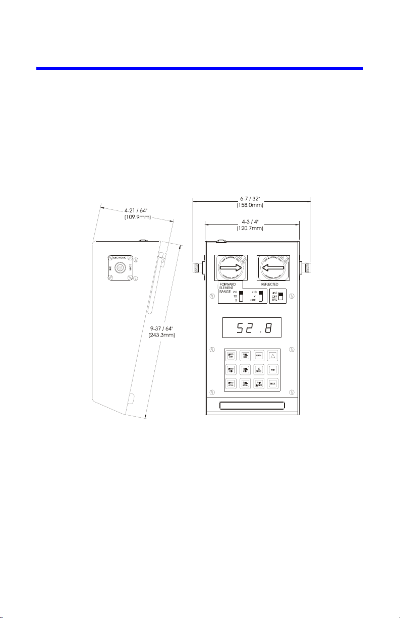
The instrument is housed in an aluminum case approximately 4-3/8 inches high
by 9-5/8 inches deep by 6-1/4 inches wide (111 mm x 244 mm x 159 mm) including connections, see Figure 1. At each end of the line section are Bird QuickChange type RF connectors which may be easily interchanged with any other
Bird QC connector. See Bird Catalog for types available.
Operating power is derived from rechargeable nickel metal hydride batteries
inside the unit or from a 115/230 VAC power source connected to the unit
through the power cord supplied with the unit.
Figure 1 Outline Drawing
2
Page 15
Chapter 2 Theory of Operation
Description of Operation
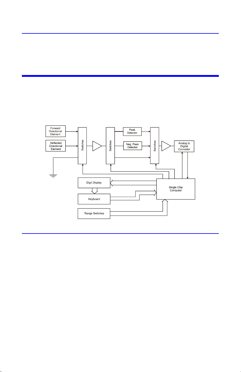
Figure 2 is a block diagram of the major functional parts of the Model 4391A RF
Wattmeter. The Microcomputer integrated circuit shown, controls all the other
portions of the instrument, which fall into two major groups.
Figure 2 Circuit Block Diagram
Keyboard, Range Switches, and Display Group
The keyboard and range switches serve only to pass information to the computer.
The display, of course, returns information from the computer to the operator. The
display, which is comprised of four seven-segment LED digits, is strobed digit by
digit left to right at a rate of approximately one digit per millisecond. This serves to
conserve battery power and drive circuitry while providing scanning for the columns of the keyboard. Each time a digit is strobed, the corresponding column of
the keyboard is read and if a key is pressed, the computer puts the code for that
key into a memory cell. The nine mode keys select which parameter is to be measured. The three modifier keys simply modify the way in which the result is displayed. The range selector switches identify to the computer the nominal full scale
values of the elements used. They have no effect on input sensitivity, which is
determined by the elements.
3
Page 16
Elements, Analog Circuitry, and A/D Converter
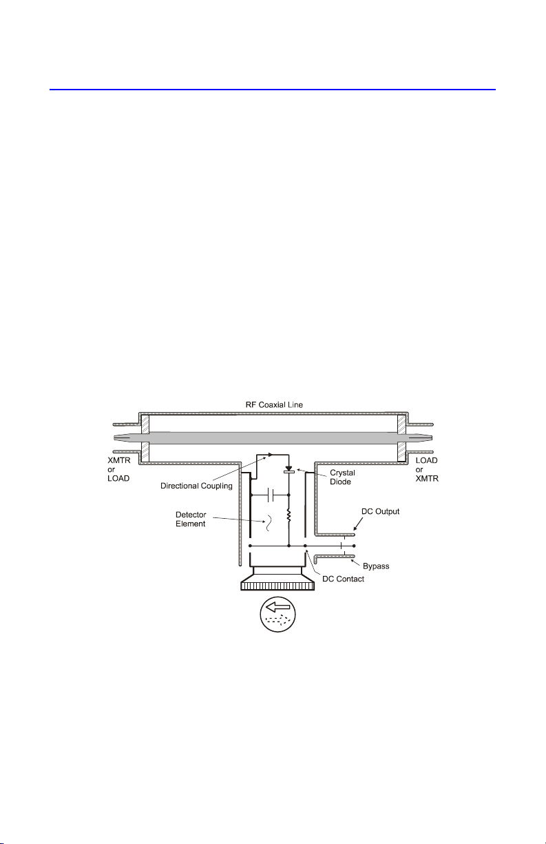
These components are controlled by the computer. The Plug-in Elements in the
line section provide low level positive voltages related to the instantaneous
value of power (see Figure 3). The first group of solid state switches selects the
forward element, the reflected element, or ground as the input to the preamplifier which boosts these signals to 0.1 to 2.0 volt range. The remaining switches
shown as two groups direct the output of the preamp to the analog-to-digital
converter either directly or through a peak or negative peak detector. The analog-to-digital converter converts the voltage to a 15 digit binary number.
Each reading output by the display is derived from up to three voltage readings
using the circuitry described above. Once these voltages are measured, all remaining operations are performed within the computer chip as follows:
The voltages are corrected for error due to dc drift in the analog circuitry. Each
voltage is converted to square root of power using stored data tables. These values
are then combined mathematically to arrive at the final result in binary. This is
used to update the registers containing the last value, the maximum value, or the
minimum value as required. Finally, the result is converted to a decimal number
and placed into a register from which the display driving routine operates.
Figure 3 Plug-In Element Schematic Diagram
The coupling circuit that samples the travelling waves is in the Plug-in Element.
The circuitry of the element and its relationship to the other components of the
Thruline Watt-meter are illustrated in the schematic diagram. Energy will be produced in the coupling circuit of the element by both mutual inductance and
capacitance from the travelling RF waves of the line section. The inductive currents will flow according to the direction of the travelling waves producing them.
The capacitive portion of these currents is independent of the direction of the
travelling waves. Therefore, assuming that the Plug-in Element remains station-
4
Page 17
ary, the coupling currents produced from the waves of one direction will add in
phase, and those produced from waves of the opposite direction will accordingly
subtract in phase. The additive or “arrow” direction is assigned to the forward
wave.
The electrical values of the element circuits are carefully balanced and designed
so that current from the reverse wave will cancel the other almost completely.
The result is directivity always higher than 25 dB, which means that the element
is highly insensitive (nulled) to the REVERSE direction wave. Being highly directional, the Thruline element is sensitive (at one setting) only to one of the travelling waves that produce standing waves by interference. Thruline Wattmeter
measurements are, therefore, independent of position along standing waves.
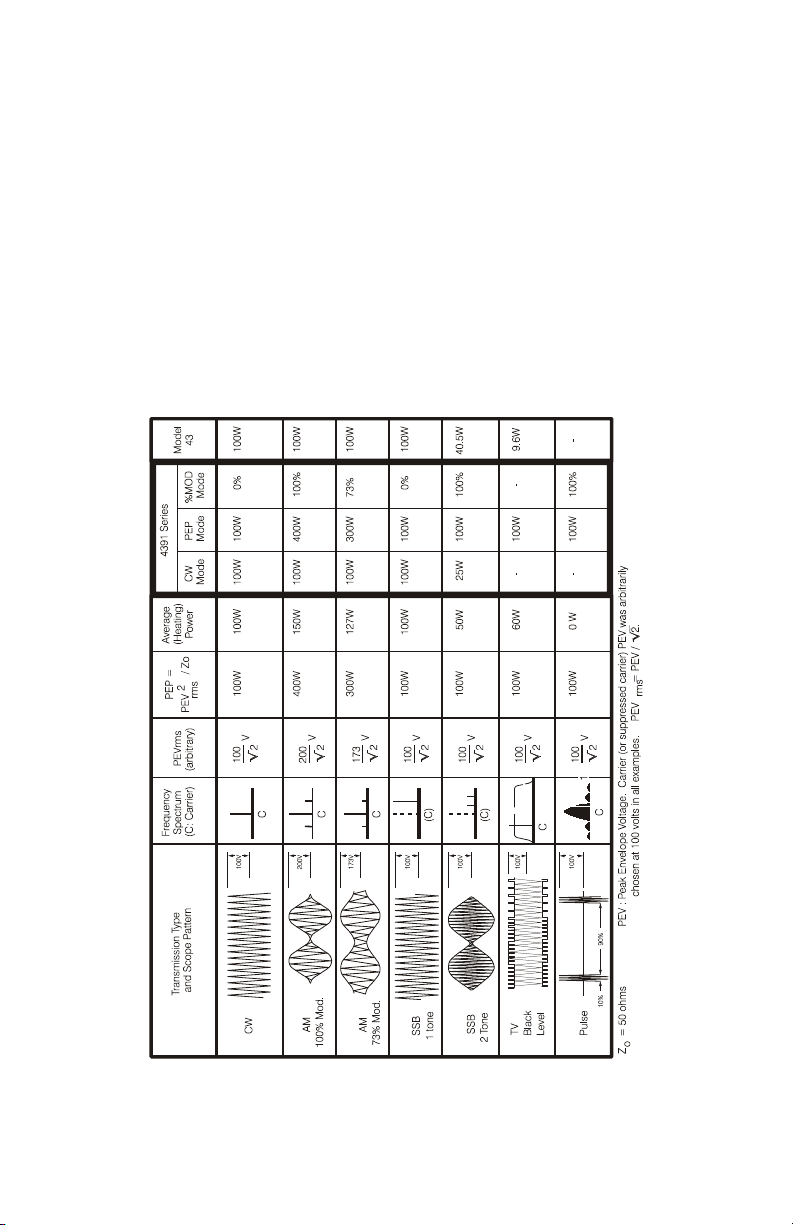
Figure 4 Readings with Various Envelopes
5
Page 18

6
Page 19
Chapter 3 Installation
The Model 4391A RF Power Analyst is completely portable and very suitable for
field or laboratory use. Its power is derived from rechargeable nickel metal
hydride batteries inside the unit or from an AC outlet via the power cord supplied with the device.
The batteries are shipped in a low charge state. It is, therefore, recommended that
you charge the instrument for 16 hours before using it for continuous operation.
Note: Battery charging at tempertures greater than 46° C (115° F)
can result in reduced operational time.
CAUTION
Long-term storage of this instrument can affect battery
performance and reduce battery life. Do not store the
instrument for long periods of time without recharging the
batteries (refer to page 18). Failure to comply may result in
reduced battery charge and shortened battery life.
Operating on AC Power
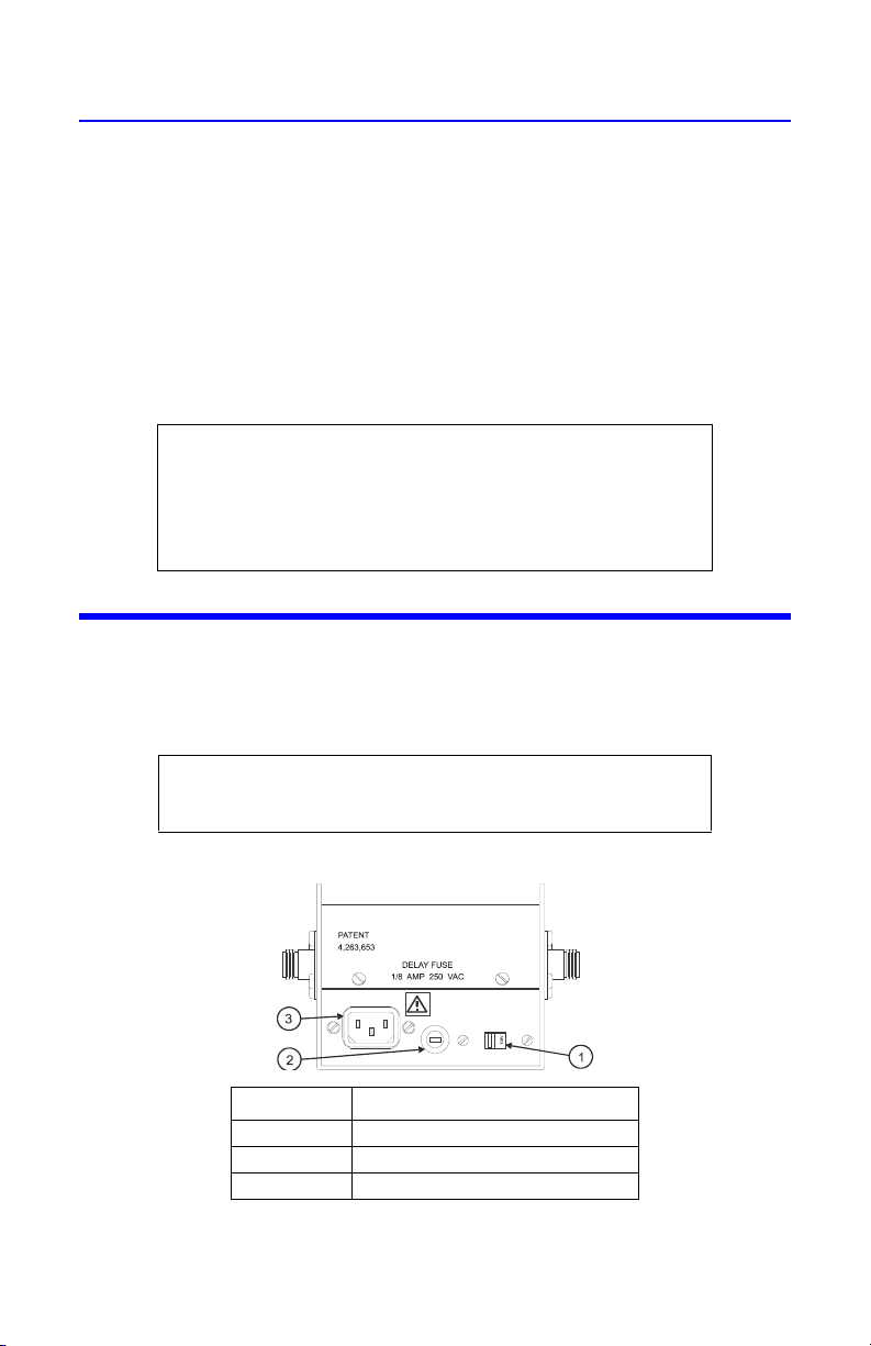
For AC power operation, the Model 4391A is simply connected to an AC receptacle using the line cord provided. The correct AC voltage is selected via a rear
panel switch (Figure 5). The meter may be operated in this manner with the batteries removed if desired.
CAUTION
Always be certain the 115/230 voltage selector is set to the
proper voltage before AC power is applied.
Figure 5 Rear Panel
Item No. Description
1 AC input voltage selector switch
2 Fuse holder
3 AC power cable connector
7
Page 20

Connections
The Model 4391A contains a short section of rigid 50 ohm coaxial air dielectric
transmission line. To make measurements relating to the travelling waves in a
coaxial line, that line must be disconnected at some convenient point to permit
the Model 4391A air line to be inserted.
Although the Model 4391A is normally supplied with two Female N-type connectors, a variety of easily interchangeable connectors are available to facilitate
connecting to the user’s system.
Once the Model 4391A is installed in the coaxial line, a Plug-in Element or a pair
of Plug-in Elements must be selected which correspond to the frequency and
power levels to be measured.
Note: The instrument is shipped with dust plugs installed in the element sockets. Remove the dust plugs to insert elements.
In order to take full advantage of the Model 4391A’s capabilities, two elements in a
10:1 ratio of power range should be used. If only one element is used, the other socket
should be filled with a dust plug or a higher power element. Also, for greatest accuracy,
the element(s) should be chosen having the lowest possible power range that will not
result in over-ranging. Table 1 lists elements required for each mode of operation.
Table 1 Plug-In Elements Required
Mode Forward Reflected
FWD CW 3
RFL CW 3
SWR 33
FWD PEP 3
RFL PEP 3
% MOD 3
FWD dBm 3
RFL dBm 3
RTN Loss 33
*. The reflected element must have a nominal power
range one tenth that of the forward element.
*
*
The higher power element is placed in the socket marked “FORWARD” and its
arrow pointed in the direction of forward power flow (toward antenna or load).
The lower power element is placed in the socket marked “REFLECTED” and is
normally pointed in the direction opposite to forward power flow. The elements
are clamped in place by the hold-down catches on the face of the line section.
These catches must be used to avoid error due to the element not contacting
the bottom or seating plate of the socket. With the element(s) in place, set the
range switches to correspond with the nominal power range of the elements.
For example, if the forward element is a 5 watt element, the switches are set at
5 and x1. For a 250 watt element they are set at 2.5 and x100. Sometimes it is
necessary to use milliwatts or kilowatts as the unit of measure. In other words, 1
watt becomes 10 x 100 milliwatts and 2500 watts becomes 2.5 x 1 kilowatts.
8
Page 21
Chapter 4 Operating Instructions
Operating Modes
The Model 4391A has nine modes of operation which are selected by pressing the
mode keys momentarily. In addition, each mode has three output options selected
by pressing the modifier keys. Detailed descriptions of the modes and output
options follow.
Reading Forward CW Power
For this measurement only a forward element is needed. Install the meter and
element according to the preceding paragraphs and move the power switch to
LINE or BAT depending on the power source desired. When powered up, the
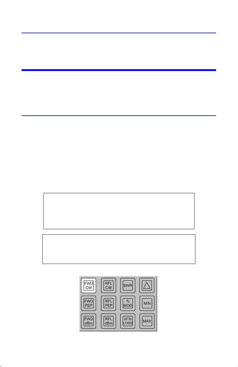
Model 4391A always goes into the forward CW power mode. If the unit is
already operating, the forward CW power mode is selected by pressing the FWD
CW key momentarily. If the applied power exceeds 120 percent of the range,
two right-facing arrow heads (i.e., “greater-than” symbols) will be displayed. The
operation of this error message does not depend on the correct setting of the
range switches by the operator, nor will the meter or its elements be damaged if
the switches are incorrectly set.
CAUTION
Never apply RF power to the Model 4391A Wattmeter unless
both line section sockets are filled with either an element or
a dust plug. If an element is used it is advisable to place the
element with the arrow at a 90° angle to the coaxial line.
Always disconnect AC power before opening the Model
4391A enclosure. Removal of at least one battery cell is also
recommended when servicing the instrument.
Figure 6 Forward Power (CW)
CAUTION
9
Page 22
The Model 4391A arrives at values of CW power by a method quite different from
CW POWER
Peak Power Minimum Power+
2
------------------------------------------------------------------------------------
⎝⎠
⎛⎞
2
=
analog meters such as the Model 43, also manufactured by Bird Electronic. While
the two instruments will agree when the measured wave is of constant amplitude,
AM or SSB waves will result in different indications (in the CW mode). This is
because the analog instrument uses the inertia of the microammeter to “timeaverage” the varying signal coming from the element, whereas the Model 4391A
uses peak and negative peak detector circuits to measure peak and minimum
square root of power and combines them using the equation:
With this technique, operation of CW mode is predictable regardless of envelope shape (see Figure 4).
Reading Reflected CW Power
Operation of the reflected CW power mode is identical to that for forward CW
power described above with two exceptions: the readings are taken from the
element in the socket marked “REFLECTED” and the range of the element is
assumed to be 1/10 the range indicated by the range switches.
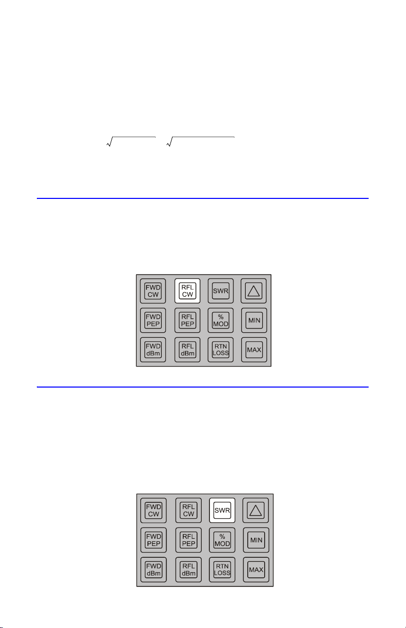
Figure 7 Reflected Power (CW)
Reading SWR
Two elements with a 10 to 1 power range ratio are required for this mode. Press
the SWR key momentarily. If average forward power is between 10% and 120% of
the scale and the average reflected power is less than 120% of the reflected element range, SWR will be displayed. If any of the above conditions are not met, an
error message will be displayed. Two arrows pointing to the right — or “greaterthan” symbols — indicate over-range, while two left-pointing arrows — or “lessthan” symbols — indicate under-range or too little power. Refer to Table 2.
Figure 8 Standing Wave Ratio (SWR)
10
Page 23
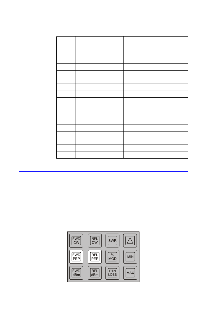
Table 2 Voltage Standing Wave Ratio (VSWR)
VSWR
Return
Loss (dB)
Reflected
Power %
VSWR
1.01 46.1 0.00 1.45 14.7 3.37
1.02 40.1 0.01 1.50 14.0 4.00
1.03 36.6 0.02 1.75 11.3 7.44
1.04 34.2 0.04 2.00 9.50 11.11
1.05 32.3 0.06 2.25 8.30 14.79
1.06 30.7 0.08 2.50 7.40 18.37
1.07 29.4 0.11 2.75 6.60 21.78
1.08 28.3 0.15 3.00 6.00 25.00
1.09 27.3 0.19 3.25 5.50 28.03
1.10 26.4 0.23 3.50 5.10 30.86
1.15 23.1 0.49 3.75 4.70 33.52
1.20 20.8 0.83 4.00 4.40 36.00
1.25 19.1 1.23 4.25 4.20 38.32
1.30 17.7 1.70 4.50 3.90 40.50
1.35 16.5 2.22 4.75 3.70 42.53
1.40 15.6 2.78 5.00 3.50 44.44
Measuring Peak Envelope Power
Return
Loss (dB)
Reflected
Power %
PEP power measurements are made in the same manner as CW power readings
described above, except that the FWD PEP and RFL PEP buttons are pressed and
the readings are displayed directly as peak power.
Note: The accuracy of measurements made with modulation having
a frequency, duty cycle, pulse width, or repetition rate outside the
instrument range cannot be assured in any mode of operation.
Figure 9 Peak Envelope Power (PEP)
11
Page 24
Measuring Amplitude Modulation
MODULATION
Peak Power Minimum Power–
Peak Power Minumum Power+
------------------------------------------------------------------------------------- 1 0 0×=
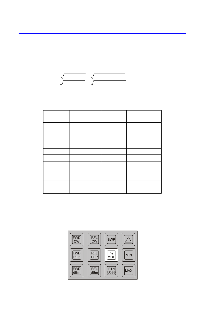
Only a forward element is required for this mode. Point the element in the direction of forward power and press % MOD. Modulation is displayed directly in percent, provided the average signal is above 10% and the PEP of the signal is below
400% of the element’s nominal full scale. For specified accuracy, the average CW
power levels must be greater than one-third of full scale. Modulation is calculated as follows:
and is therefore limited to the range of 0 to 99.9 percent. Over-modulation will be
indicated as 99.9 percent. Refer to Table 3.
Table 3 Amplitude Modulation
Peak /
CW Power
1.00 0 2.40 55
1.10 5 2.56 60
1.21 10 2.72 65
1.32 15 2.89 70
1.44 20 3.06 75
1.56 25 3.24 80
1.69 30 3.42 85
1.82 35 3.61 90
1.96 40 3.80 95
2.10 45 4.00 100
2.25 50
% Modulation Peak /
CW Power
% Modulation
Because of the threshold of the RF diode, a modulated signal which has a minimum power level below 0.3 percent of full scale will result in high modulation
reading with uncertain accuracy.
Figure 10 Amplitude Modulation (%)
12
Page 25
Measuring Power in dBm
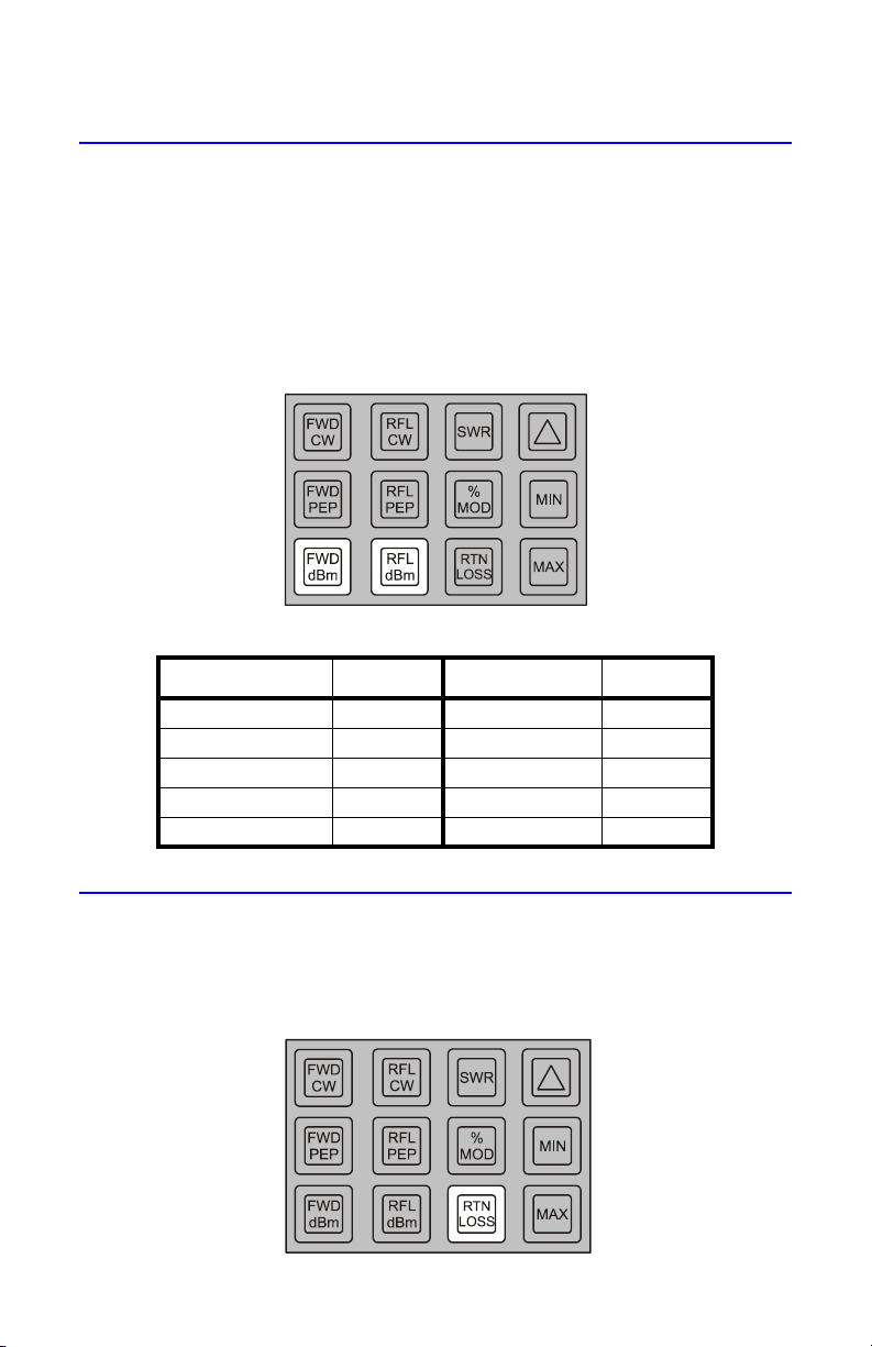
Operation of the forward and reflected dBm modes is identical to the forward and
reflected CW power modes, except that the resulting reading is converted to dB
above 1 milliwatt before it is displayed. It should be noted that in doing this conversion, the range set on the slide switches is assumed to be watts rather than
kilowatts or milliwatts. If it is not, 30.0 must be added to all dBm readings when
the range is in kilowatts, or subtracted from all readings when it is in milliwatts. An
error message is displayed if CW power is more than 24 dB below, or peak power
is more than 6 dB above the nominal element range. Refer to Table 4.
Figure 11 CW Power in dBm
Table 4 Watts/dBm Equivalents
Power dBm Power dBm
1 milliwatt 0 4 watts 36
10 milliwatts 10 10 watts 40
100 milliwatts 20 20 watts 43
1 watt 30 40 watts 46
2 watts 33 100 watts 50
Measuring Return Loss
The measurement of return loss is the same as that of SWR except that the
result is displayed in dB. In other words a reading of 21.65 indicates that
reflected power is 21.6 dB down from forward power.
Figure 12 Return Loss, Insertion Loss, or Attenuation
13
Page 26

Insertion Loss or Attenuation
Attenuation or insertion loss can be measured directly using an external single
port line section (P/N 4230-006-1), a dc feed-in adapter (P/N 4381-050), and a dc
cable (P/N 3170-058-6). The Model 4391A is inserted at the source end of the
device being measured. The second line section is inserted at the load end and
its dc output is routed by the dc cable to the adapter inserted in the REFLECTED
socket of the Model 4391A. Both elements are in this case pointed in the direction of forward power flow. If the two elements do not have a ten to one ratio, a
correction factor must be added to or subtracted from the “return loss” reading
see Table 5, depending on the ratio of the elements.
Table 5 Correction Factors
Ratio of
Elements
1:1 –10 100:1 10
2:1 –7 200:1 13
2.5:1 –6 250:1 14
4:1 –4 400:1 16
5:1 –3 500:1 17
10:1 0 1000:1 20
20:1 3 2000:1 23
25:1 4 2500:1 24
40:1 6 4000:1 26
50:1 7 5000:1 27
Added dB
Ratio of
Elements
Added dB
Monitoring Maximum and Minimum Readings
While operating in any of the modes described, the Model 4391A will continuously
keep track of the highest and lowest reading obtained. This action begins after ten
reading cycles to allow time for the peak detectors to settle from the previous mode.
To recall the maximum or minimum reading, depress and hold the MAX or MIN key.
When these keys are released, the meter goes back to displaying the current value of
the parameter being measured. Recalling max or min does not stop the meter from
continuing to monitor the current value and updating the minimum and maximum
registers. To clear the minimum and maximum register, the mode key must be pressed
again or a new mode selected. For example, if CW power deviations are monitored,
the Model 4391A is installed as described at the beginning of this section and turned
on, then the power source is turned on and allowed to stabilize. Once the system has
stabilized, press FWD CW to clear the MAX and MIN registers. At any time during test
the MAX and MIN keys can be used to recall the maximum and minimum values without affecting the test. However, pressing the FWD CW key or changing modes will clear
the registers.
14
Page 27
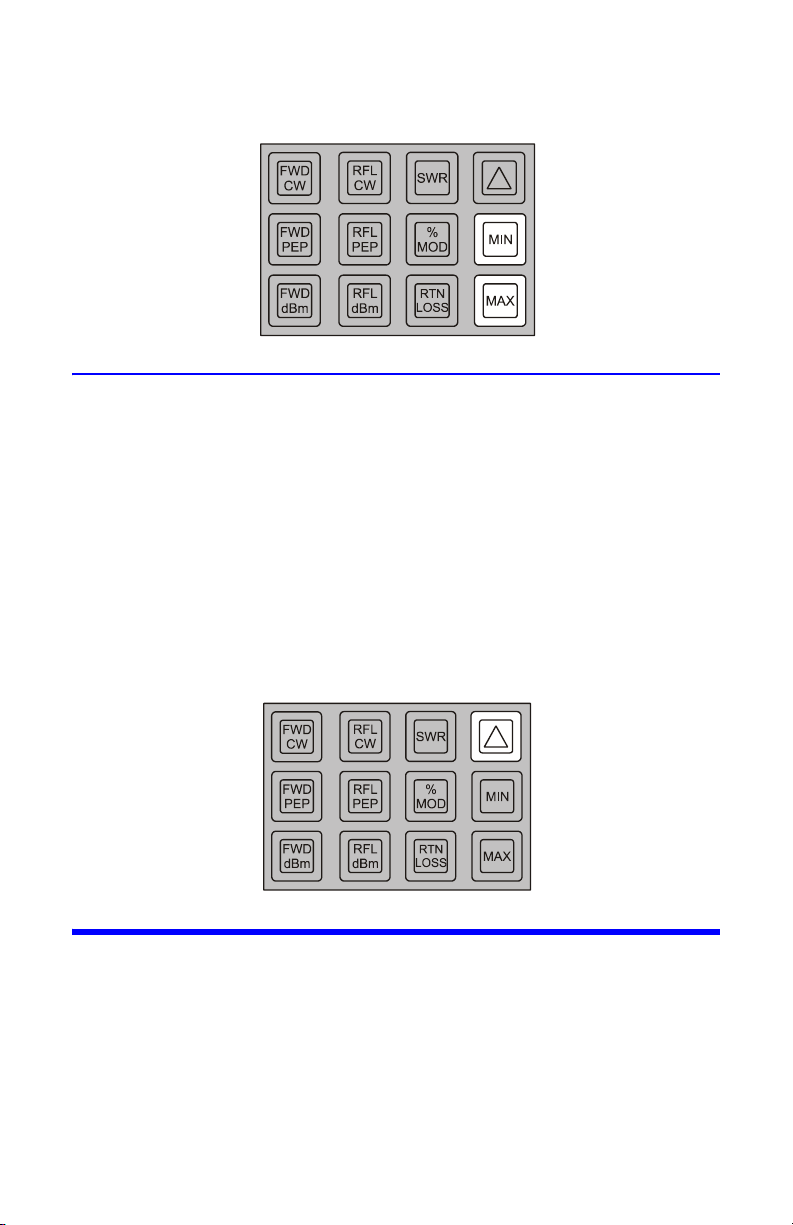
Figure 13 Maximum or Minimum Readings
Using the Peaking Aid
The peaking aid is useful for making adjustments to optimize any of the parameters which the Model 4391A measures. After the mode is selected, press the
delta (Δ) key momentarily. This blanks the least significant digit of the display,
and replaces it with a right-facing arrow head if the measured quantity is
increasing or a left-facing arrow head if it is decreasing. If there is no change, the
digit is left blank. To find a peak, begin making the adjustment in whichever
direction produces a right-facing arrow and continue slowly in that direction
until the arrow head turns around. At this point the peak has been reached. To
check to make sure the peak has not been passed, press the MAX key to read the
highest value read and release it to read the current value. The two should be
the same. Desired minimum levels (e.g. of reflected power or of SWR) are found
in a similar manner.
Figure 14 Peaking Aid (D)
Battery Care
With average use, the nickel metal hydride batteries in the 4391A will power the unit
for 12 hours before needing recharged. The 4391A will maintain rated accuracy until
all the decimal points light, indicating that recharging is required. To recharge, connect AC power to the unit. To fully charge the batteries requires approximately 16
hours. To prolong the life of the batteries, it is recommended that you periodically
allow the batteries to discharge until the decimal points light before recharging. If
the batteries lose the ability to hold a charge they should be replaced. See
Chapter 5, Maintenance, page 17 for important precautions regarding static electricity when opening the housing.
15
Page 28

WAR NIN G
Use only Nickel Metal Hydride (NiMH) batteries that have a
minimum capacity of 4500 milliamper hours (mAh). Do not
install batteries that are not Nickel Metal Hydride. Do not install
NiMH batteries that have less than 4500 mAh capacity. Failure to
comply may result in damage to the batteries, damage to the
instrument, and injury to personnel from battery chemicals.
CAUTION
Long-term storage of this instrument can affect battery
performance and reduce battery life. Do not store the
instrument for long periods of time without recharging the
batteries (refer to page 18). Failure to comply may result in
reduced battery charge and shortened battery life.
16
Page 29
Chapter 5 Maintenance
The 4391A RF Power Analyst was designed and built to provide many years of
trouble free service. This section provides the information needed to prevent
and correct equipment failure.
Preventive Maintenance
To avoid unnecessary damage, always observe the following cautions:
CAUTION
The RF Power Analyst is a rugged and portable instrument
intended for field use. However, it should not be
unnecessarily exposed to extreme environmental conditions.
CAUTION
When not in use, store the RF Power Analyst with the LINE/
OFF/BATT switch is in the off position.
CAUTION
Charge the batteries for 16 hours prior to extended use of the RF
Power Analyst. Refer to "Battery Care" on page 15.
Cleaning and Inspection
Perform a periodic inspection to ensure that the RF power analyst is always
operational.
Note: Any damage noticed during inspection should be listed and
repaired before use.
• Visually inspect the equipment for loose or damaged parts.
• Wipe dust and dirt from the front panel and lower housing.
• Remove dirt with mild detergent and a soft cloth.
WAR NIN G
Use dry cleaning solvents in a well ventilated area. Avoid
excessive inhalation of solvent fumes, since they can be toxic in
heavy concentrations. Always wear eye protection and avoid skin
contact with the solvent.
• Clean the inside of the line section bores using cotton swab stick damp-
ened with alcohol.
17
Page 30

• Inspect the RF connectors for any sign of wear or damage. Replace if
necessary.
• Clean the connectors with alcohol or any acceptable dry cleaning fluid.
Long-term Storage
Do not store the instrument for long periods of time without recharging the
batteries. When the instrument is stored for long periods of time without use,
the batteries will loose their charge and also loose the ability to reach full
charge when put into service. To restore the battery charge, perform a full
charge for 16 hours. If the batteries are not fully charged after 16 hours, completely discharge the batteries then perform a full charge again. If necessary,
repeat this discharge and charge cycle up to three times. If the batteries do
not remain charged after three discharge-charge cycles, replace the batteries.
WARNING
Use only Nickel Metal Hydride (NiMH) batteries that have a
minimum capacity of 4500 milliamper hours (mAh). Do not
install batteries that are not Nickel Metal Hydride. Do not
install NiMH batteries that have less than 4500 mAh
capacity. Failure to comply may result in damage to the
batteries, damage to the instrument, and injury to
personnel from battery chemicals.
Calibration
The RF Power Analyst should be calibrated once each year or after any repair.
Required Equipment
Refer to Table 7 for test equipment needed to calibrate the RF Power Analyst.
Table 6 Required Calibration Equipment
Equipment Recommended Model
Calibrator/Source Keithly Model 263 or equivalent
Cable Assembly
(1 Required)
DC Feed-in Element
(1 required)
18
BNC to BNC (1 meter long)
Bird Electronic 4381-050
Page 31
Initial Setup
Note: On a clean flat workspace perform the following setup proce-
dure:
1. Remove the front panel. Refer to "Front Panel Removal" on page 23.
2. Insert a DC feed-in adapter into the FWD element of the socket.
3. Insert a metal dust plug (supplied with the instrument) into the RFL element
socket.
4. Connect a BNC to BNC cable assembly from the output of calibrator/source
to the DC feed-in adapter.
5. Set the RF Power Analyst range switches to the 10 and x100 positions.
6. Connect AC power and place the LINE/OFF/BATT switch to the LINE setting.
7. Switch on the Calibrator/Source.
8. Allow it to warm up for at least one hour.
9. Set the Calibrator/Source to output 30 ±0.05 microamps.
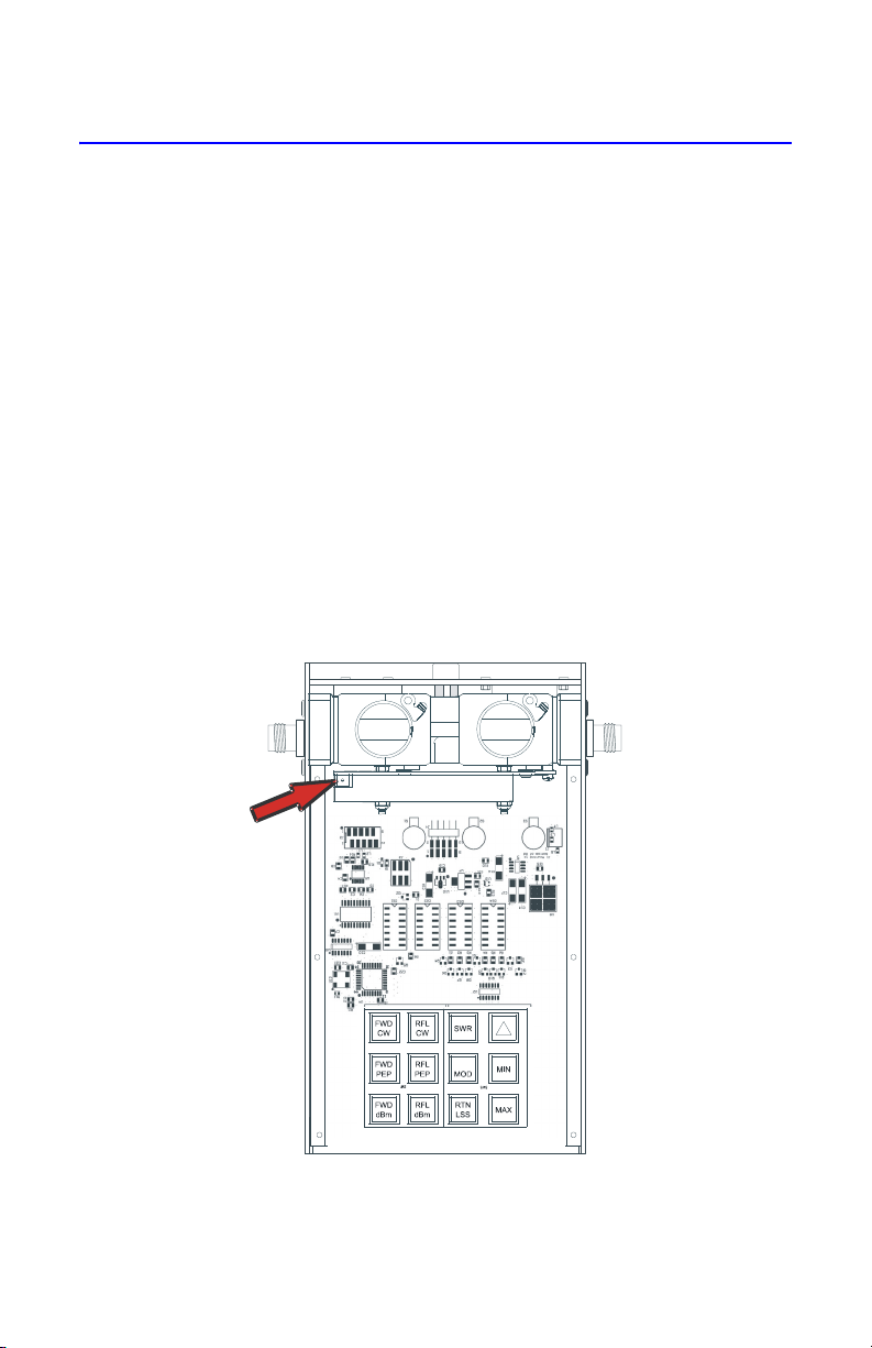
10. Adjust potentiometer, R25 (Figure 15 on page 19), until the RF Power Analyst Displays 1000 ±5.
Figure 15 Calibration Potentiometer
19
Page 32
Element Wiper Contact Adjustment
CAUTION
If the element cannot be fully inserted into the socket, do not
force it. You might damage the element.
CAUTION
Be careful not to bend the spring out so far that it interferes
with insertion of the elements.
Note: Continuous insertion or rotation of the element might cause a
slight change in the position of the contact spring in the element
socket. If the contact spring changes position, you might experience
erratic power readings.
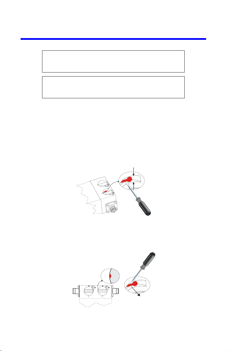
1. Place the flat side of a small flat head screwdriver behind the contact bar as
indicated.
2. Bend the contact bar so that the contact rests in the center of the slot adjacent to the element socket (Figure 16).
Figure 16 Adjust Element Contact Up and Down
3. Bend the contact slightly toward the center of the element socket bore.
Note: Ensure the profile of the element contact is visible when viewing
the element socket from the top of the socket bore (Figure 17).
Figure 17 Adjust Element Contact In and Out
Note: If the contact is accidently moved too far into the element
bore, the element will not slide into the socket.
4. Move the contact back into the recessed area and repeat the process.
20
Page 33

Troubleshooting
General
The troubleshooting instructions are intended to aid in fault isolation. This is
accomplished through the use of a troubleshooting table.
First, locate the symptom(s) in the problem column of Table 7. In some cases the
same fault can have more than one symptom and more than one possible remedy. Compare the possible causes until you arrive at a suspected fault. Once a
fault has been isolated, repair or replace the defective components.
Note: Always recalibrate the RF Power Analyst after repairing the fault.
Table 7 Trouble-shooting
PROBLEM POSSIBLE CAUSE REMEDY
Inaccurate
power
readings
High
standing
waves
Short battery
life
Will not
operate from
AC line
RF Power Analyst
uncalibrated
Defective Plug-in
Elements
Intermittent connection
at the element wiper
Loose hold down catch Readjust catch to
Worn line section Replace line
Defect on Data
Acquisition PC board
assembly
Dirty Connectors Clean the
Worn or damaged
connectors
Foreign objects in line
section
115/230V switch in
wrong position
Damaged/worn
batteries
115/230V switch in
wrong position
Blown fuse Replace blown fuse.
Defective line cord Repair or replace.
Recalibrate.
Replace defective
elements.
Adjust the element
wiper contact.
hold element
securely in place.
section.
Replace the PC
board assembly
(attached to line
section).
connectors.
Replace the
connectors
Remove object from
the line section.
Set 115/230V switch
to correct position.
Replace the
batteries.
Set 115/230V switch
to correct position.
21
Page 34

PROBLEM POSSIBLE CAUSE REMEDY
Display
indicates “0”
Power
One
segment of a
display does
not light
All decimal
points stay lit
Same
segment on
all displays
doesn’t light
One or more
keys do not
function
Element wiper not
contacting the element
Defective Plug-in
Element
Defect on Data
Acquisition PC board
assembly
Defective Display Replace the display.
Low charge on the
batteries
Defective circuit
component
Defective circuit
component
Defect on Main PC
board
Readjust the
element wiper to
make good contact.
Replace Plug-In
Element.
Replace the PC
board assembly
(attached to line
section).
Recharge the
batteries.
Replace the Main
circuit board
assembly.
Replace the Main
circuit board
assembly.
Replace the Main
circuit board
assembly.
Disassembly
Be sure that the power cable is unplugged before opening
the wattmeter case. The power supply capacitor, C1, can
retain a dangerous charge that must be removed before
touching. Always have another person standing by who is
This instrument contains static sensitive electronic
components. Before opening or servicing the unit, make
sure that you understand and practice electrostatic
discharge component handling. Failure to comply may result
22
WARNING
trained in electric shock first aid.
CAUTION
in permanent damage to sensitive components.
Page 35
Front Panel Removal
1. Disconnect AC power from the instrument.
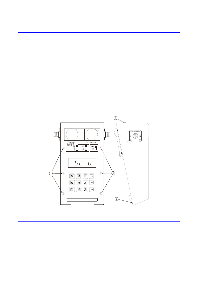
2. Remove the six screws that secure the front panel to the Main PCB supports
(Figure 18 on page 23, item 1).
3. Remove the two screws and lock washers that secure the front panel at the bottom of the housing (item 2).
4. Remove the two screws and lock washers that secure the front panel at the
back of the housing (item 3).
5. Lift the front panel from the housing.
Note: Be careful to clear the line section blocks.
6. Remove pads from the three toggle switches.
Figure 18 Removing Front Panel
Main Printed Circuit (PC) Board Removal
1. Remove the front panel. Refer to "Front Panel Removal" on page 23.
2. Disconnect cable assembly at header (J4) (Figure 19 on page 24, item 1).
3. Remove the six screws and washers that secure the circuit board supports
to the housing (item 2).
4. Lift the Main PC board.
Note: Locate the cable coming from the power supply assembly.
5. Disconnect the cable assembly at header (J1). (Figure 19 on page 24, item 3).
23
Page 36
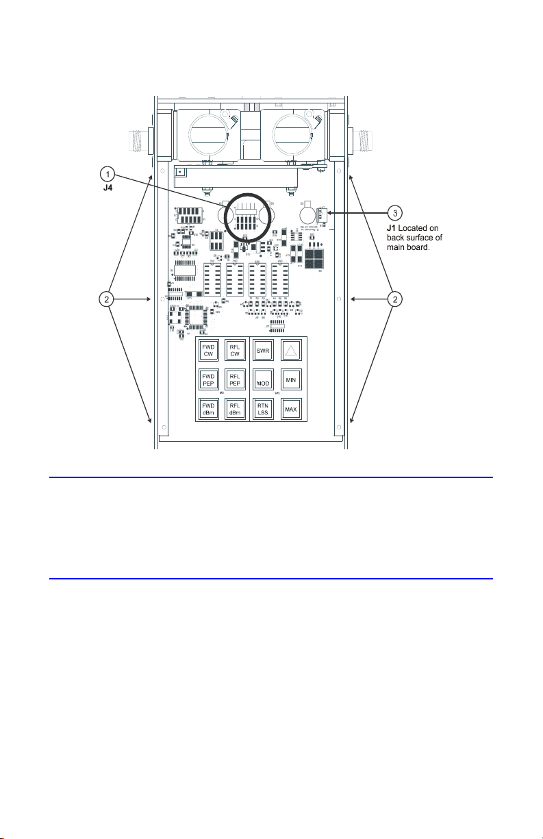
Figure 19 Removing Main PCB
QC Connectors Removal
1. Remove the eight screws (four on each connector) that secure the connectors to the housing (Figure 20, item 1).
2. Remove the two “QC” connectors (item 2) by pulling them away from the
line section assembly.
Line Section Removal
1. Remove the QC connectors (page 24).
2. Remove the four screws and lock washers that secure line section assembly to
the housing (item 3).
3. Spread apart the sides of the lower housing assembly far enough to allow
the line section assembly to be removed.
Note: Use minimum pressure when performing this step.
24
Page 37
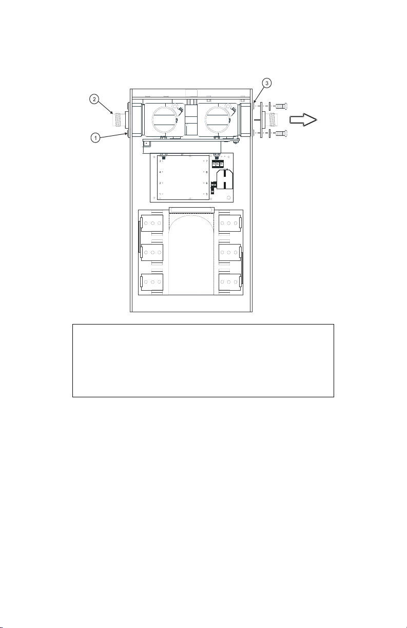
Figure 20 Removing QC Connectors and Line Section
CAUTION
This instrument contains static sensitive electronic components.
Before opening or servicing the unit, make sure that you
understand and practice electrostatic discharge component
handling. Failure to comply may result in permanent damage to
sensitive components.
4. Remove the two hex nuts (Figure 21, item 5) that secure the PCB.
5. Remove the cover (item 6) and spacers (item 7).
6. Disconnect the ribbon cable assembly from the PC board header (P1).
7. Remove the two screws (item 4) that secure the PCB to the line section then
pull the PC board assembly (item 3) away from the line section subassembly.
8. Remove the spacers (item 2).
9. Remove keying beads (item 1) from the element wiper contacts on the PC
board assembly.
25
Page 38
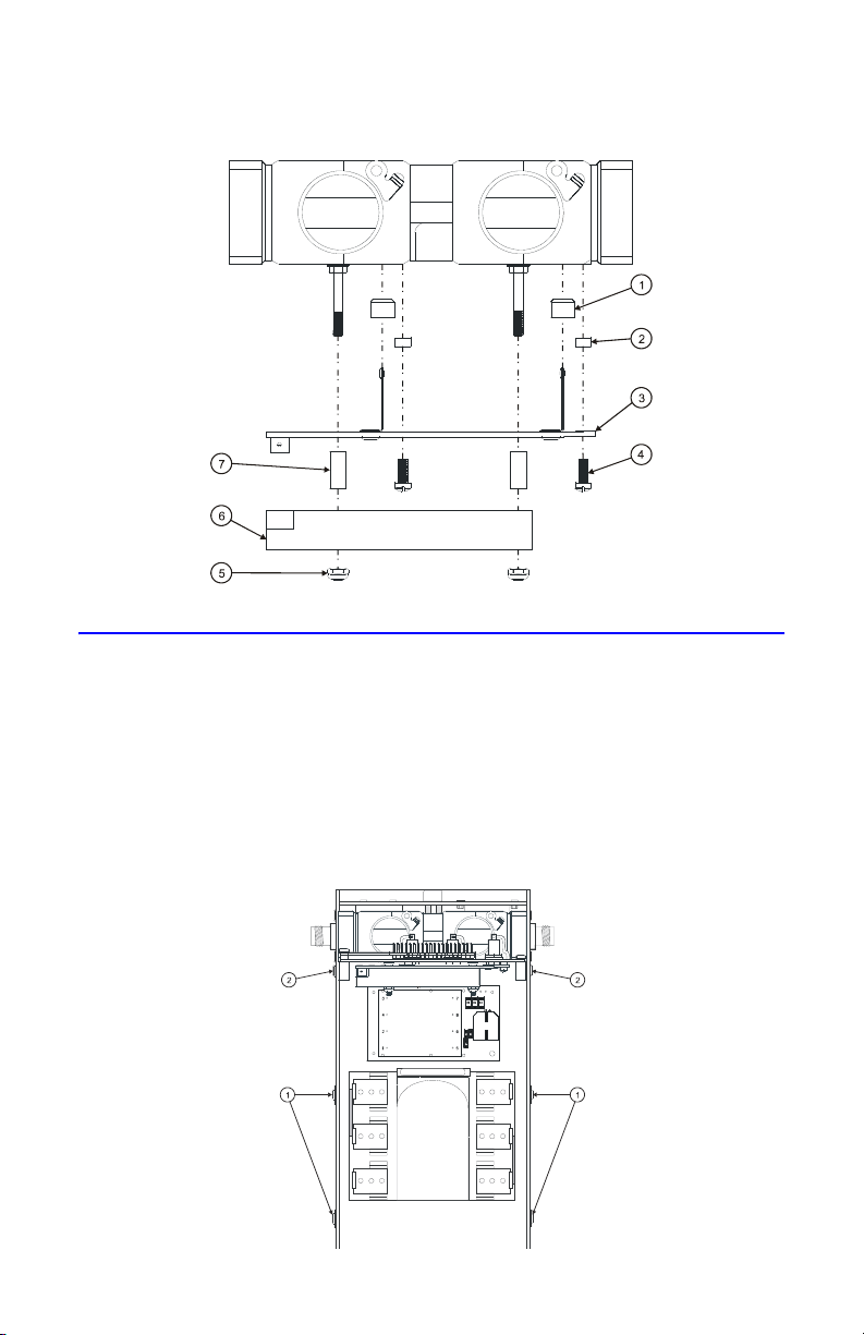
Figure 21 Removing Line Section PCB
Battery Replacement
1. Remove the front panel (refer to "Front Panel Removal" on page 23) .
2. Remove the four screws and lock washers (Figure 22, item 1) that secure
the Main PCB.
3. Loosen, but do not remove the remaining two screws that secure the Main
PCB (item 2).
4. Tilt the Main PC board assembly up to expose the batteries then tighten the two
screws to secure the PCB.
Figure 22 Tilt Main PCB to Expose Batteries
26
Page 39
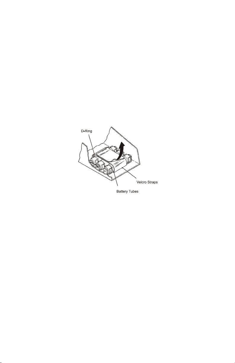
5. Unfasten the velcro strap and remove it from the D-ring. (Figure 23).
Note: The polarity orientation of the batteries must reamin consistent.
6. Remove the three battery tubes from the battery clips then remove two
batteries from each tube.
7. Install new batteries into the tubes then secure the tubes in the battery clips.
Note: Be sure to observe proper polarity.
8. Lower and secure the Main PC board assembly
9. Replace and secure the front cover.
10. Charge the batteries for 16 hours before using the instrument.
Figure 23 Battery Replacement
27
Page 40
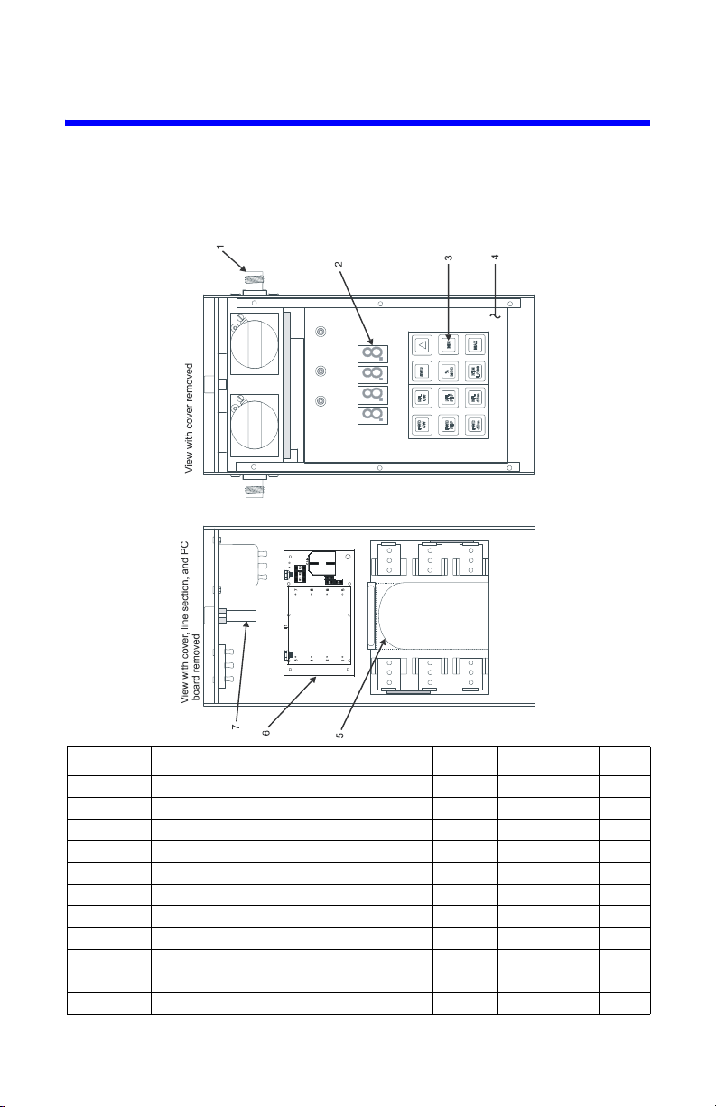
Parts List
This section contains an illustrated list of all authorized replacement parts for
the 4391A RF power Analyst. Parts are grouped into major assemblies and subassemblies.
Figure 24 Parts Drawing
Item No. Description Part No. Qty
Figure 24
1 Connector, QC F-N 4240-062 2
2 LED display, (DS1 - DS4) 5-1337 4
3 Keyboard legend 4386-012 1
4 PC board, Main, assembly 4391C007 1
5 Velcro strap 5-1958 1
6 PC board assy (includes rectifier circuit) 4391B041 1
7 Fuse, Slo-Blo, IEC 1/8 amp 5A2257-7 1
N/S Battery (rechargeable) “C” cell 5A1230 6
N/S Dust plug 3610-031 2
N/S Cable, power cord, 115V / 230V 4421-055 1
N/S = not shown in figure
28
Page 41
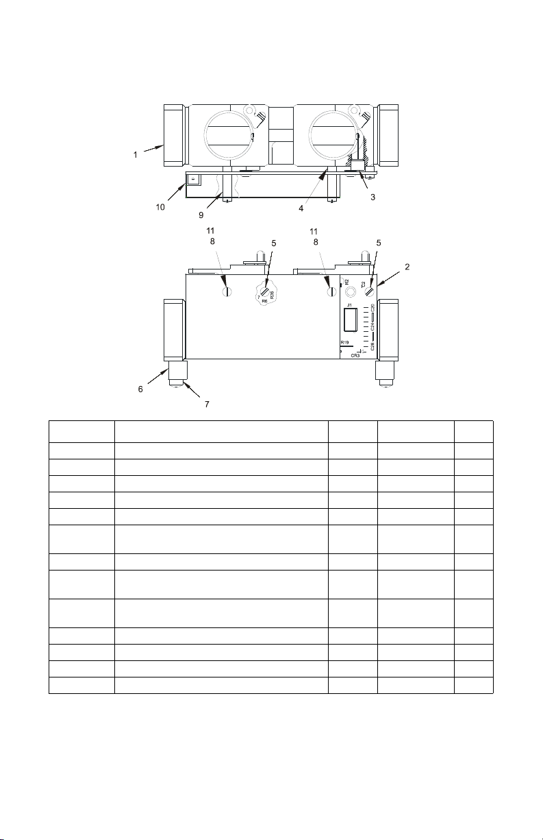
Figure 25 Line Section Assembly (S/N 1723 & below)
Item No. Description Part No. Qty
Figure 25
1 Line Section, Subassembly 4381-005 1
2 PC Board, Data Acquisition Assy 4391A006 1
3 Bead, Keying 4391-026 2
4 Spacer 4391-027 2
5 Screw, Machine, filister head,
No. 4-40, 1/4 in. lg, sst
6 Support 4381-029 2
7 Screw, Machine, filister head,
No. 8-32, 1/2 in. lg, sst
8 Screw, Machine, filister head,
No. 4-40, 7/8 in. lg, sst
9 Spacer 4391-035-1 2
10 Cover, PC Board 4391-034 1
11 Lock Washer, No. 4 internal sst COML 2
N/A Line Section Complete 4391-014 1
COML 2
COML 4
COML 2
29
Page 42
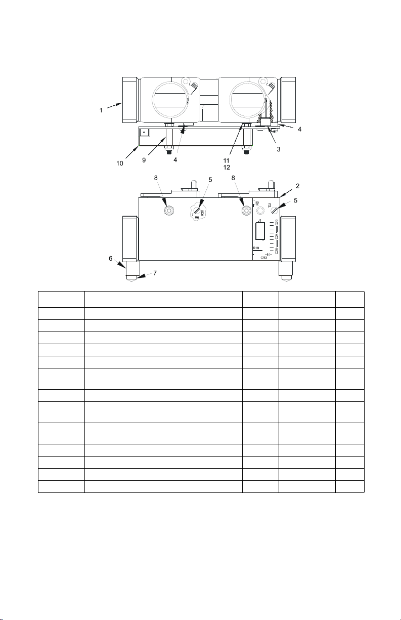
Figure 26 Line Section Assembly (S/N 1724 & above)
Part No. Description Part No. Qty
Figure 26
1 Line Section, Subassembly 4381-005 1
2 PC Board, Data Acquisition Assy 4391A006 1
3 Bead, Keying 4391-026 2
4 Spacer 4391-027 2
5 Screw, Machine, filister head,
No. 4-40, 1/4 in. lg, sst
6 Support 4381-029 2
7 Screw, Machine, filister head,
No. 8-32, 1/2 in. lg, sst
8 Hex Nut, with nylon insert, No. 4-40 1131-1013-002
COML 2
COML 4
9 Spacer 4391-035-1 2
10 Cover, PC Board 4391-034 1
11 Lock Washer, No. 4 internal sst COML 2
12 Standoff, Threaded 4391-038 2
30
Page 43

Customer Service
Any maintenance or service procedure beyond the scope of those in this chapter
should be referred to a qualified service center.
If you need to return the unit for any reason, request an RMA through the Bird Technologies website (link shown below). All instruments returned must be shipped prepaid and to the attention of the RMA number.
Bird Service Center
30303 Aurora Road
Cleveland (Solon), Ohio 44139-2794
Fax: (440) 248-5426
E-mail: [email protected]
For the location of the Sales Office nearest you, visit our website at:
http://www.bird-technologies.com
31
Page 44

Specifications
Measuring
RF Transmission in 50 ohm lines
Medium
RF Power Range*100 mW to 10 kW full scale using Bird Plug-in Elements.
Accuracy not guaranteed with components not supplied by
Bird
Usable Over-
*
Range
To 120% of scale on CW, PEP, SWR, and Return loss
functions. To 400% of scale (PEP) on dBm and 0%
modulation.
*
Frequency Range
450 kHz to 2.7 GHz
Sampling Range 2-3 readings per second
Settling Time 10 seconds (worst case)
†
Accuracy
Power Readings
CW
PEP
SWR
% Modulation
Return Loss
±5% of full scale
±8% of full scale
±10% of reading
‡
±5%
±0.3 dB to corresponding SWR value
Impedance 50 ohms
Insertion SWR 1.05 max to 1000 MHz
Pulse Parameters
(square pulses)
Pulse Width
0.8 μsec. min.
**
Repetition
Rate
Duty Cycle
25 pps min.
0.01% min.
RF Line
Connections
Standard
Optional
Bird Quick Change “QC” Female N
Any Standard AN “QC” type
Temperature
Range
Operating
Storage
Input Power
Requirements
Voltage
Frequency
Power
Batteries
Battery Life
10ºC to 45ºC (50ºF to 113º F)
-20ºC to 45ºC (-4ºF to 113º F)
100-130 or 200-230 VAC (Switch Selectable) or 7.2 Vdc
(internal battery)
50-60 Hz
6 Watts
6-1.2 V NiMH C size (Rechargeable)
12 hours approx. (reduced after high tempterature
charging)
Weight 5-3/4 lb (2.6 kg)
32
Page 45

*. Frequency band and power range is determined by the Plug-in
Elements selected. See Bird Catalog for availability. Some modes
require two elements in a 10:1 power ratio.
†. VSWR and return loss functions settle in less than 1 second.
‡. For CW power levels greater than one-third of full scale, accuracy of
the percent modulation mode is 5% from 0 to 90% and +10% from 90
to 100%. Modulation frequency is 25 to 100,000 Hz; except for “A”
and “B” elements: 25 to 20,000 Hz; and “H” elements: 25-10,000 Hz.
**.For “A” and “B” elements the minimum pulse width is 1.5
microseconds. For “H” elements the minimum pulse width is 15
microseconds.
33
Page 46

Bird Technologies
Limited Warranty
All products manufactured by Seller are warranted to be free from defects in material and
workmanship for a period of one (1) year, unless otherwise specified, from date of shipment and to
conform to applicable specifications, drawings, blueprints and/or samples. Seller’s sole obligation
under these warranties shall be to issue credit, repair or replace any item or part thereof which is
proved to be other than as warranted; no allowance shall be made for any labor charges of Buyer for
replacement of parts, adjustment or repairs, or any other work, unless such charges are authorized in
advance by Seller.
If Seller’s products are claimed to be defective in material or workmanship or not to conform to
specifications, drawings, blueprints and/or samples, Seller shall, upon prompt notice thereof, either
examine the products where they are located or issue shipping instructions for return to Seller
(transportation charges prepaid by Buyer). In the event any of our products are proved to be other
than as warranted, transportation costs (cheapest way) to and from Seller’s plant, will be borne by
Seller and reimbursement or credit will be made for amounts so expended by Buyer. Every such claim
for breach of these warranties shall be deemed to be waived by Buyer unless made in writing within
ten (10) days from the date of discovery of the defect.
The above warranties shall not extend to any products or parts thereof which have been subjected to
any misuse or neglect, damaged by accident, rendered defective by reason of improper installation or
by the performance of repairs or alterations outside of our plant, and shall not apply to any goods or
parts thereof furnished by Buyer or acquired from others at Buyer’s request and/or to Buyer’s
specifications. Routine (regularly required) calibration is not covered under this limited warranty. In
addition, Seller’s warranties do not extend to the failure of tubes, transistors, fuses and batteries, or
to other equipment and parts manufactured by others except to the extent of the original
manufacturer’s warranty to Seller.
The obligations under the foregoing warranties are limited to the precise terms thereof. These
warranties provide exclusive remedies, expressly in lieu of all other remedies including claims for
special or consequential damages. SELLER NEITHER MAKES NOR ASSUMES ANY OTHER WARRANTY
WHATSOEVER, WHETHER EXPRESS, STATUTORY, OR IMPLIED, INCLUDING WARRANTIES OF
MERCHANTABILITY AND FITNESS, AND NO PERSON IS AUTHORIZED TO ASSUME FOR SELLER ANY
OBLIGATION OR LIABILITY NOT STRICTLY IN ACCORDANCE WITH THE FOREGOING.
34
 Loading...