

Page 1

INSTRUCTION BOOK FOR
RF DIRECTIONAL
®
THRULINE
WATTMETER
MODEL 43
Also Covers Models
4305, 4330, 4431, 4521-27, and 43P
Electronic Corporation
Cleveland (Solon) Ohio USA
© Copyright 1998 by Bird Electronic Corporation
Instruction Book Part Number 920-43 Revision. C
Thruline® and Termaline® are registered trademarks of
Bird Electronic Corporation
Page 2

Page 3
Safety Precautions
The following are general safety precautions that are not necessarily related
to any specific part or procedure, and do not necessarily appear elsewhere
in this publication. These precautions must be throughly understood and
applied to all phases of operation and maintenance.
Keep Away From Live Circuits
Operating personnel must at all times observe normal safety precautions. Do
not replace components inside equipment with the high voltage supply turned
on. To avoid casualties, always remove power.
Do Not Service Or Adjust Alone
Under no circumstances should any person reach into an enclosure for the
purpose of service or adjustment of equipment except in the presence of
someone who is capable of rendering aid.
Safety Earth Ground
An uninterruptible earth safety ground must be supplied from the main
power source to test instruments. Grounding one conductor of a two conductor
power cable is not sufficient protection. Serious injury or death can occur if
this grounding is not properly supplied.
Shock Hazard
Do not attempt to remove RF transmission line while power is present.
Radiated RF power is a potential health hazard.
i
Page 4
Bird Model 43 Wattmeter
Resuscitation
Personnel working with or near high voltages should be familiar with modern
methods of resuscitation.
Safety Symbols
WARNING
Warning notes call attention to a procedure which, if not correctly
performed, could result in personal injury.
CAUTION
Caution notes call attention to a procedure which, if not correctly
performed, could result in damage to the instrument.
This symbol appears on the equipment indicating there is important
information in the instruction manual regarding that particular area.
Warning Statements
The following warnings appear in the text where there is danger to operating
and maintenance personnel, and are repeated here for emphasis.
WARNING
When operating this equipment in conjunction with RF power of 200
watts or higher, the potential of the center conductor of the RF line
section will be 100 volts or higher. Do not contact the center conductor.
If cleaning becomes necessary, shut off the RF power.
ii
Page 5
WARNING
Leaking RF energy is a potential health hazard. Never attempt to
connect or disconnect equipment from the transmission line while RF
power is being applied. Severe burns, electrical shock, or death can
occur.
Caution Statement
The following equipment caution appears in the text whenever the equipment
is in danger of damage, and is repeated here for emphasis.
CAUTION
When making low reflection readings using a more sensitive element,
take care to insert the element so that it senses reflected power only.
Do not rotate the element in the socket so that it is subjected to
forward power. This can result in damage to the Plug-In Element, the
microammeter, or both.
Safety Statements
USAGE
ANY USE OF THIS INSTRUMENT IN A MAN-
NER NOT SPECIFIED BY THE MANUFAC-
TURER MAY IMPAIR THE INSTRUMENTS
SAFETY PROTECTION.
USO
EL USO DE ESTE INSTRUMENTO DE MANERA
NO ESPECIFICADA POR EL FABRICANTE,
PUEDE ANULAR LA PROTECCIÓN DE SEGURI-
DAD DEL INSTRUMENTO.
iii
Page 6
Bird Model 43 Wattmeter
BENUTZUNG
WIRD DAS GERÄT AUF ANDERE WEISE VER-
WENDET ALS VOM HERSTELLER BESCHRIE-
BEN, KANN DIE GERÄTESICHERHEIT
BEEINTRÄCHTIGT WERDEN.
UTILISATION
TOUTE UTILISATION DE CET INSTRUMENT
QUI NEST PAS EXPLICITEMENT PRÉVUE PAR
LE FABRICANT PEUT ENDOMMAGER LE DIS-
POSITIF DE PROTECTION DE LINSTRUMENT.
IMPIEGO
QUALORA QUESTO STRUMENTO VENISSE
UTILIZZATO IN MODO DIVERSO DA COME
SPECIFICATO DAL PRODUTTORE LA PROZ-
IONE DI SICUREZZA POTREBBE VENIRNE
COMPROMESSA.
SERVICE
SERVICING INSTRUCTIONS ARE FOR USE BY
SERVICE-TRAINED PERSONNEL ONLY. TO
AVOID DANGEROUS ELECTRIC SHOCK, DO
NOT PERFORM ANY SERVICING UNLESS
QUALIFIED TO DO SO.
iv
SERVICIO
LAS INSTRUCCIONES DE SERVICIO SON PARA
USO EXCLUSIVO DEL PERSONAL DE SERVI-
CIO CAPACITADO. PARA EVITAR EL PELIGRO
DE DESCARGAS ELÉCTRICAS, NO REALICE
NINGÚN SERVICIO A MENOS QUE ESTÉCA-
PACITADO PARA HACERIO.
Page 7
WARTUNG
ANWEISUNGEN FÜR DIE WARTUNG DES
GERÄTES GELTEN NUR FÜR GESCHULTES
FACHPERSONAL.
ZUR VERMEIDUNG GEFÄHRLICHE, ELEK-
TRISCHE SCHOCKS, SIND WARTUNGSAR-
BEITEN AUSSCHLIEßLICH VON
QUALIFIZIERTEM SERVICEPERSONAL DUR-
CHZUFÜHREN.
ENTRENTIEN
LEMPLOI DES INSTRUCTIONS DENTRETIEN
DOIT ÊTRE RÉSERVÉ AU PERSONNEL FORMÉ
AUX OP ÉRATIONS DENTRETIEN. POUR
PRÉVENIR UN CHOC ÉLECTRIQUE
DANGEREUX, NE PAS EFFECTUER DEN-
TRETIEN SI LON NA PAS ÉTÉ QUALIFIÉ
POUR CE FAIRE.
ASSISTENZA TECNICA
LE ISTRUZIONI RELATIVE ALLASSISTENZA
SONO PREVISTE ESCLUSIVAMENTE PER IL
PERSONALE OP PORTUNAMENTE AD-
DESTRATO. PER EVITARE PERICOLOSE
SCOSSE ELETTRICHE NON EFFETTUARRE AL-
CUNA RIPARAZIONE A MENO CHE QUALIFI-
CATI A FARLA.
v
Page 8
Bird Model 43 Wattmeter
RF VOLTAGE MAY BE PRESENT IN RF ELE-
MENT SOCKET -KEEP ELEMENT IN SOCKET
DURING OPERATION.
DE LA TENSION H.F. PEAT ÊTRE PRÉSENTE
DANS LA PRISE DE LÉLÉMENT H.F. - CON-
SERVER LÉLÉMENT DANS LA PRISE LORS DE
LEMPLOI.
HF-SPANNUNG KANN IN DER HF-ELEMENT-
BUCHSE ANSTEHEN - ELEMENT WÄHREND
DES BETRIEBS EINGESTÖPSELT LASSEN.
PUEDE HABER VOLTAJE RF EN EL ENCHUFE
DEL ELEMENTO RF - MANTENGA EL ELE-
MENTO EN EL ENCHUFE DURANTE LA OPER-
ACION.
IL PORTAELEMENTO RF PUÒ PRESENTARE
VOLTAGGIO RF -TENERE LELEMENTO NELLA
PRESA DURANTE IL FUNZIONAMENTO.
vi
Page 9
About This Manual
This instruction book covers Thruline RF Directional Wattmeters Models:
43 43P 4305A 4331
4431 4521 4522 4523
4525 4526 4527
This instruction book is arranged so that the essential safety information
appears in the front of the book. Reading the Safety Precautions Section
before operating the equipment is strongly advised.
The remainder of this instruction book is divided into Chapters and Sections.
At the beginning of each chapter, a general overview describes the contents
of that chapter.
Operation
First time users should read Chapter 1 Introduction, Chapter 2 Theory
of Operation, and Chapter 3 Installation, to get an overview of equipment
capabilities and installation. An experienced operator can refer to Chapter 4
Operating Instructions. All instructions necessary to operate the equip-
ment appear in this chapter.
Maintenance
All personnel should be familiar with preventative maintenance found in
Chapter 5 Maintenance. If a failure should occur, the troubleshooting
section will aid in isolating and repairing the failure.
vii
Page 10

Bird Model 43 Wattmeter
Parts
For location of parts, refer to the parts list and associated drawings in
Chapter 5.
Changes To The Manual
We have made every effort to ensure this manual is accurate. If you
should discover any errors or if you have suggestions for improving
this manual, please send your comments to our factory. This manual
may be periodically updated. When inquiring about updates to this
manual, refer to the part number and revision level on the title page.
viii
Page 11

Table of Contents
Safety Precautions. . . . . . . . . . . . . . . . . . . . . . . . i
WarningStatements. .....................ii
Caution Statement. . . . . . . . . . . . . . . . . . . . . . iii
Safety Statements. . . . . . . . . . . . . . . . . . . . . . iii
About This Manual. . . . . . . . . . . . . . . . . . . . . . vii
Introduction. . . . . . . . . . . . . . . . . . . . . . . . . . . 1
Purpose and Function. . . . . . . . . . . . . . . . . . . . . 1
Performance Characteristics and Capabilities. . . . . . . . . 1
Specifications. . . . . . . . . . . . . . . . . . . . . . . . . . 4
Theory of Operation. . . . . . . . . . . . . . . . . . . . . . . 7
Travelling Wave Viewpoint. . . . . . . . . . . . . . . . . . . 7
Coupling Circuit. . . . . . . . . . . . . . . . . . . . . . . . . 7
Standing Wave Ratio vs Reflected/Forward Power Ratio. . 9
Load Power. . . . . . . . . . . . . . . . . . . . . . . . . . . 9
Measurement And Monitoring of Transmitter Power. . . . 14
Testing of Lines, Connectors, Filters, Etc.. . . . . . . . . . 14
FrequencyResponse.....................16
ImpedanceMismatch.....................17
Installation. . . . . . . . . . . . . . . . . . . . . . . . . . . 19
Portability. . . . . . . . . . . . . . . . . . . . . . . . . . . 19
ix
Page 12

Bird Model 43 Wattmeter
Connections. . . . . . . . . . . . . . . . . . . . . . . . . . 19
Remote Installation. . . . . . . . . . . . . . . . . . . . . . 20
Operating Instructions. . . . . . . . . . . . . . . . . . . . 23
Zero Adjust. . . . . . . . . . . . . . . . . . . . . . . . . . 23
General. ...........................24
NormalOperation.......................25
Maintenance. . . . . . . . . . . . . . . . . . . . . . . . . . 31
Troubleshooting........................31
Cleaning. . . . . . . . . . . . . . . . . . . . . . . . . . . . 32
Preventive Maintenance. . . . . . . . . . . . . . . . . . . 33
Line Section Care. . . . . . . . . . . . . . . . . . . . . . . 33
Contact Adjustment. . . . . . . . . . . . . . . . . . . . . . 33
Calibration Checks - Thruline Wattmeter vs
TermalineWattmeters. ...................34
Model 43 Replacement Parts List. . . . . . . . . . . . . . . . . . . 35
Model 4431 Thruline Wattmeter. . . . . . . . . . . . . . . . . . . . 38
Theory of Operation. . . . . . . . . . . . . . . . . . . . . 38
Operation. ..........................40
Maintenance..........................40
Model 4431 Replacement Parts List. . . . . . . . . . . . . 41
Series 4520 Thruline Wattmeters. . . . . . . . . . . . . . . . . . . 42
Installation...........................42
Theory of Operation, Operating Instructions and Mainte-
nance Sections. . . . . . . . . . . . . . . . . . . . . . . . 43
Series 4520 Replacement Parts List. . . . . . . . . . . . 43
Model 4305A Thruline Wattmeter. . . . . . . . . . . . . . . . . . . 44
x
Page 13

Model 4305A Replacement Parts List. . . . . . . . . . . . 45
Model 4330 Thruline Wattmeter. . . . . . . . . . . . . . . 45
Model 4330/31 Replacement Parts List. . . . . . . . . . . 46
Model 43P Peak Wattmeter. . . . . . . . . . . . . . . . . . . . . . 46
Model 43P Specifications. . . . . . . . . . . . . . . . . . . 47
Operation. ..........................47
Peak Detector Response. . . . . . . . . . . . . . . . . . . 47
Model 43P Peak Calibration. . . . . . . . . . . . . . . . . 48
Maintenance..........................49
Customer Service. . . . . . . . . . . . . . . . . . . . . . . 50
xi
Page 14

Bird Model 43 Wattmeter
xii
Page 15
Chapter 1
Introduction
Purpose and Function
This instruction book covers the use and operation of the basic Model 43
Thruline Wattmeter. These instructions also apply to other units that are
very similar to the Model 43 in electrical characteristics and operation.
These different models and their variations (refer to About This Manual for
a complete listing) are also included in this book; however, the operational
procedures and, in most cases, the electrical specifications of the Model 43
apply to these units as well. The basic difference in the majority of these
units is physical, being panel rack mounted versions of the Model 43 Thruline
Wattmeter. However, two of the units are similar in appearance but differ
in as much as they have an RF sampler port included. The Model 43P has
peak power handling capabilities.
All differences pertinent to these units can be found in the specifications for
each of these models, in the back of this book.
The Model 43 Thruline Wattmeter is an insertion-type RF wattmeter, de-
signed to measure power flow and load match in 50 ohm coaxial transmission
lines. It is intended for use on CW, AM, FM, and TV modulation envelopes,
but not pulsed modes. The Model 43, when used in 50 ohm applications, has
an insertion VSWR of less than 1.05 to 1, up to a frequency of 1000 MHz.
The meter is direct reading in watts, expanded down scale for easy reading
and is graduated 25, 50, and 100 watts full scale. The power ranges used
are determined by the Plug-In Elements, which fall in various power and
frequency ranges (refer to the Bird Electronic Corporation Catalog).
Performance Characteristics and Capabilities
The Model 43 Thruline Wattmeter is a portable unit contained in a die cast
aluminum housing, with a formed metal enclosure on the back which is easily
removed. Included with the unit is a carrying strap, four rubber bumpers on
1
Page 16
Bird Model 43 Wattmeter
the base, and four rubber bumpers on the back, which allow the Model 43
to stand (vertical) or lie flat (horizontal) when used. For additional protection,
the microammeter is specially shock mounted. A slotted screw is provided
on the lower front face of the meter for zeroing the pointer. Below the meter,
the RF line section face protrudes slightly from the wattmeter housing with
the Plug-In Element socket in the center.
A shielded cable connects the microammeter to the dc jack which is attached
to the side of the RF line section casting. This cable, 32 inches long, permits
removal of the RF line section from the wattmeter housing. Meter connections
may be maintained with any installations outside of the housing.
Inside the dc jack assembly, there is a filter capacitor which shunts the meter
circuit to prevent misreadings caused by stray RF energy existing in the
Plug-In Element. Mounted on the dc jack is a phosphor bronze spring finger,
which protrudes through a lateral hole and into the Plug-In Element socket
of the RF line section.
The spring finger has a button on its end which mates with the contacts of
the Plug-In Element. The silver plated brass RF line section is precision
made to provide the best possible impedance match to the coaxial RF
transmission line in which the Model 43 is inserted. The ends of the line
section are nested in mating slots to provide additional mechanical support.
At each end of the line section are Bird Quick-Change (QC) type RF
connectors, which may be quickly interchanged with any other Bird QC
connector by removing the four screws on the mounting flanges. The watt-
meter housing does not interfere with any connector changes.
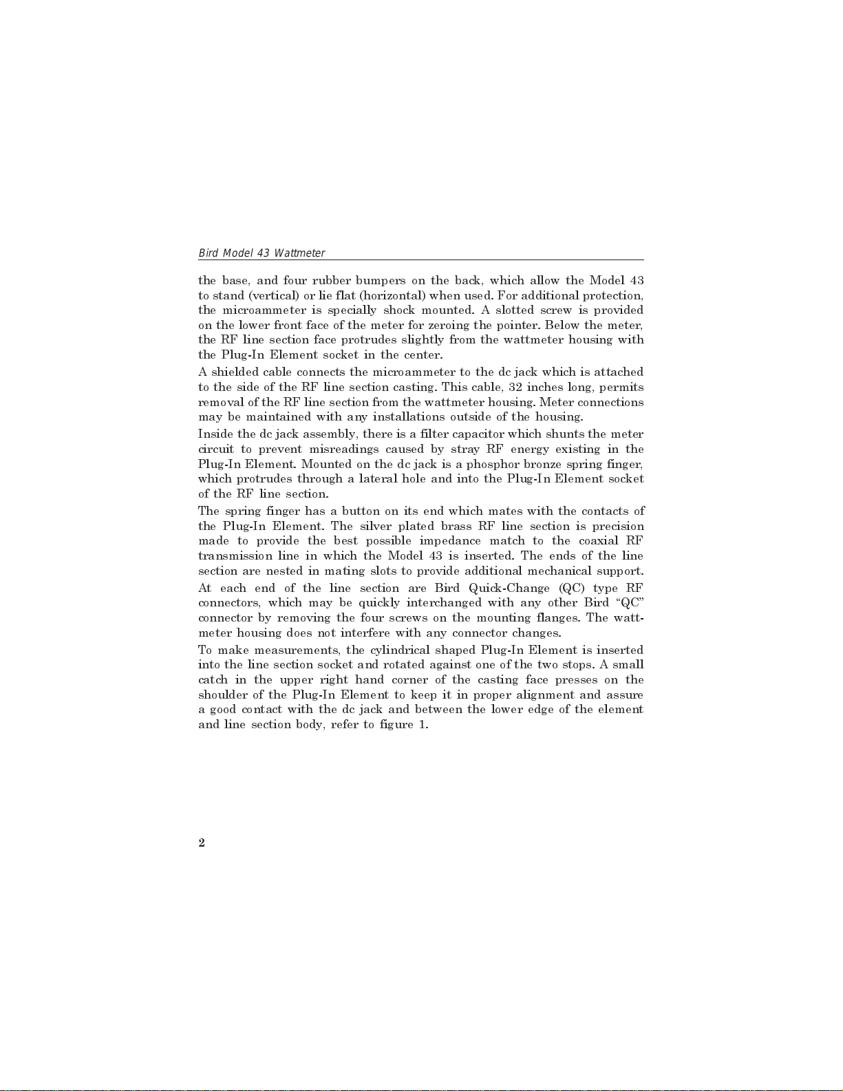
To make measurements, the cylindrical shaped Plug-In Element is inserted
into the line section socket and rotated against one of the two stops. A small
catch in the upper right hand corner of the casting face presses on the
shoulder of the Plug-In Element to keep it in proper alignment and assure
a good contact with the dc jack and between the lower edge of the element
and line section body, refer to figure 1.
2
Page 17
S
Contac
Introduction
Figure 1
Stop Pin
Raised Stop Edge
Stop Pin
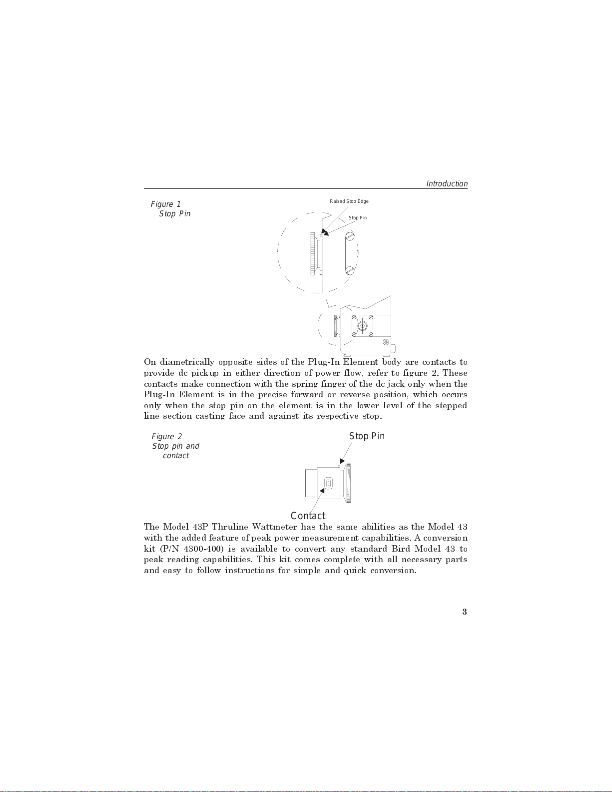
On diametrically opposite sides of the Plug-In Element body are contacts to
provide dc pickup in either direction of power flow, refer to figure 2. These
contacts make connection with the spring finger of the dc jack only when the
Plug-In Element is in the precise forward or reverse position, which occurs
only when the stop pin on the element is in the lower level of the stepped
line section casting face and against its respective stop.
Figure 2
Stop pin and
contact
top Pin
t
The Model 43P Thruline Wattmeter has the same abilities as the Model 43
with the added feature of peak power measurement capabilities. A conversion
kit (P/N 4300-400) is available to convert any standard Bird Model 43 to
peak reading capabilities. This kit comes complete with all necessary parts
and easy to follow instructions for simple and quick conversion.
3
Page 18
Bird Model 43 Wattmeter
Specifications
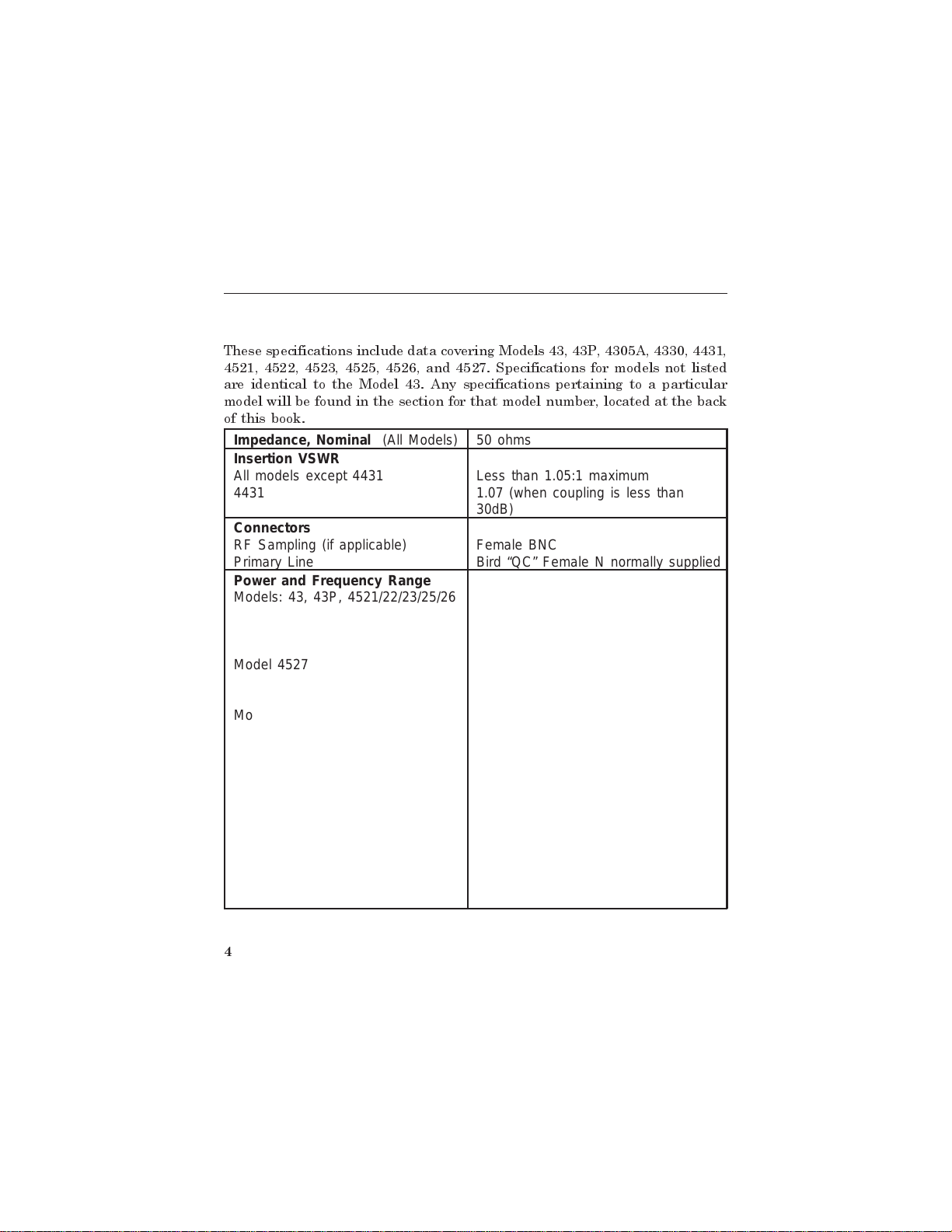
These specifications include data covering Models 43, 43P, 4305A, 4330, 4431,
4521, 4522, 4523, 4525, 4526, and 4527. Specifications for models not listed
are identical to the Model 43. Any specifications pertaining to a particular
model will be found in the section for that model number, located at the back
of this book.
Impedance, Nominal (All Models) 50 ohms
Insertion VSWR
All models except 4431
4431
Connectors
RF Sampling (if applicable)
Primary Line
Power and Frequency Range
Models: 43, 43P, 4521/22/23/25/26
Less than 1.05:1 maximum
1.07 (when coupling is less than
30dB)
Female BNC
Bird “QC” Female N normally supplied
100mW-10kW Frequency range from
0.45 to 2700 MHz (depending on
element).
Model 4527
Model 4431
Model 4305
Model 4330
4
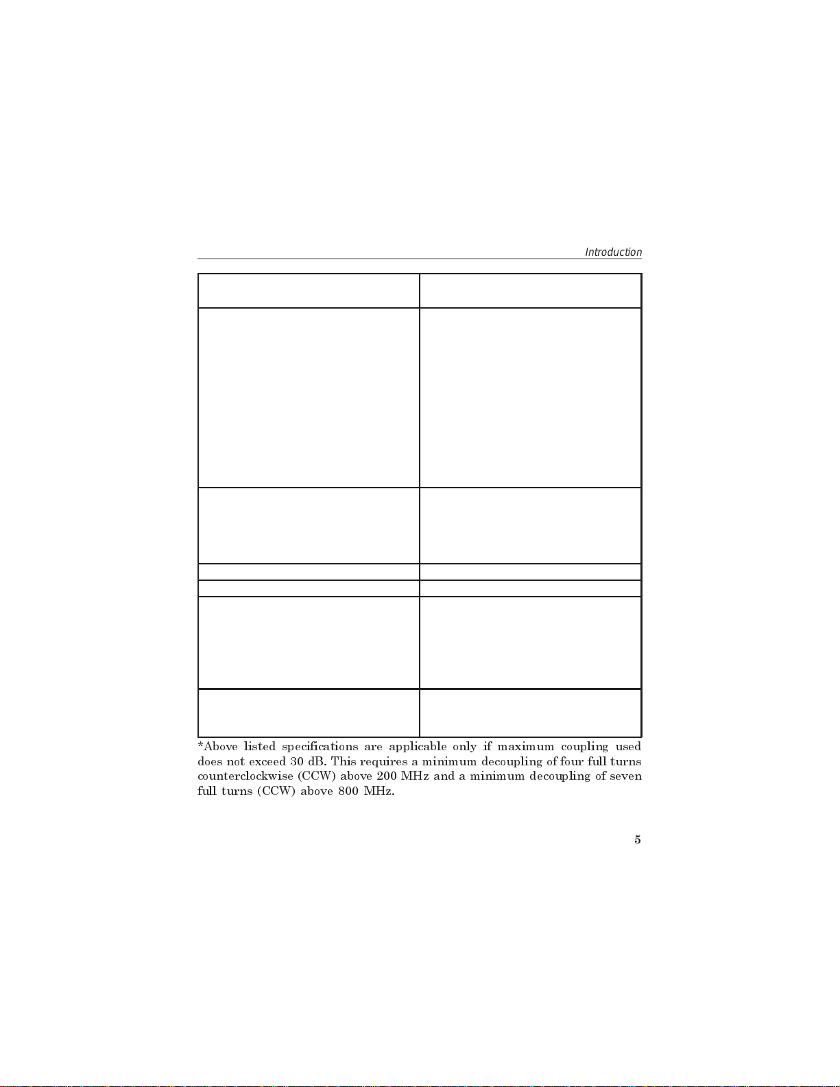
1000W maximum 2-200MHz
500W maximum from 200-512MHz
5000W maximum from 2-30MHz
1000W maximum from 30-1000MHz
(applicable only when coupling is
less than 30dB).
25kW Maximum from 0.45-2.5 MHz,
10kW from 2-30 MHz.
5000 W Maximum from 2-30 MHz.
1000 W Maximum from 30-1000 MHz
(applicable only when coupling is
less than 30 dB).
Page 19
Introduction
Accuracy (All Models CW)
(Model 43P, Peak Power)
± 5% of full scale.
± 8% of full scale.
Dimensions, Nominal
Models 43
3-5/8"L x 4"W x 6-7/8"H
(92.1 x 101.6 x 174.6 mm)
Model 4431
3-27/32"L x 4"W x 6-7/8"H
(97.6 x 101.6 x 174.6 mm)
Model 4305A
4-5/32"L x 3-27/32"W x 6-53/64"H
(105.6 x 98 x 173 mm)
Models 4521/22/23/25/26/27
19" W x 5-7/32" H x 1-11/16" D
(483 x 133 x 43mm)
Weight, Nominal
Model 43
Model 43P
Model 4431
Model 4305A
3 lb. (1.36 kg)
4 lb. (1.8 kg)
3-1/2 lb. (1.59 kg)
3-1/4 lb. (1.47 kg)
Operating Position Any
Finish (All Models) Grey Powder Coat
RF Coupling
Model 4527
Approx. -53 dB from 512 MHz down
to 10 MHz decreasing to -70 dB
between 10 and 2 MHz.
Model 4431
Adjustable, 15-70 dB
Insertion Loss (Model 4431)
2-512 MHz.
512-1000 MHz
0.1dB Maximum
0.2dB Maximum*
*Above listed specifications are applicable only if maximum coupling used
does not exceed 30 dB. This requires a minimum decoupling of four full turns
counterclockwise (CCW) above 200 MHz and a minimum decoupling of seven
full turns (CCW) above 800 MHz.
5
Page 20
Bird Model 43 Wattmeter
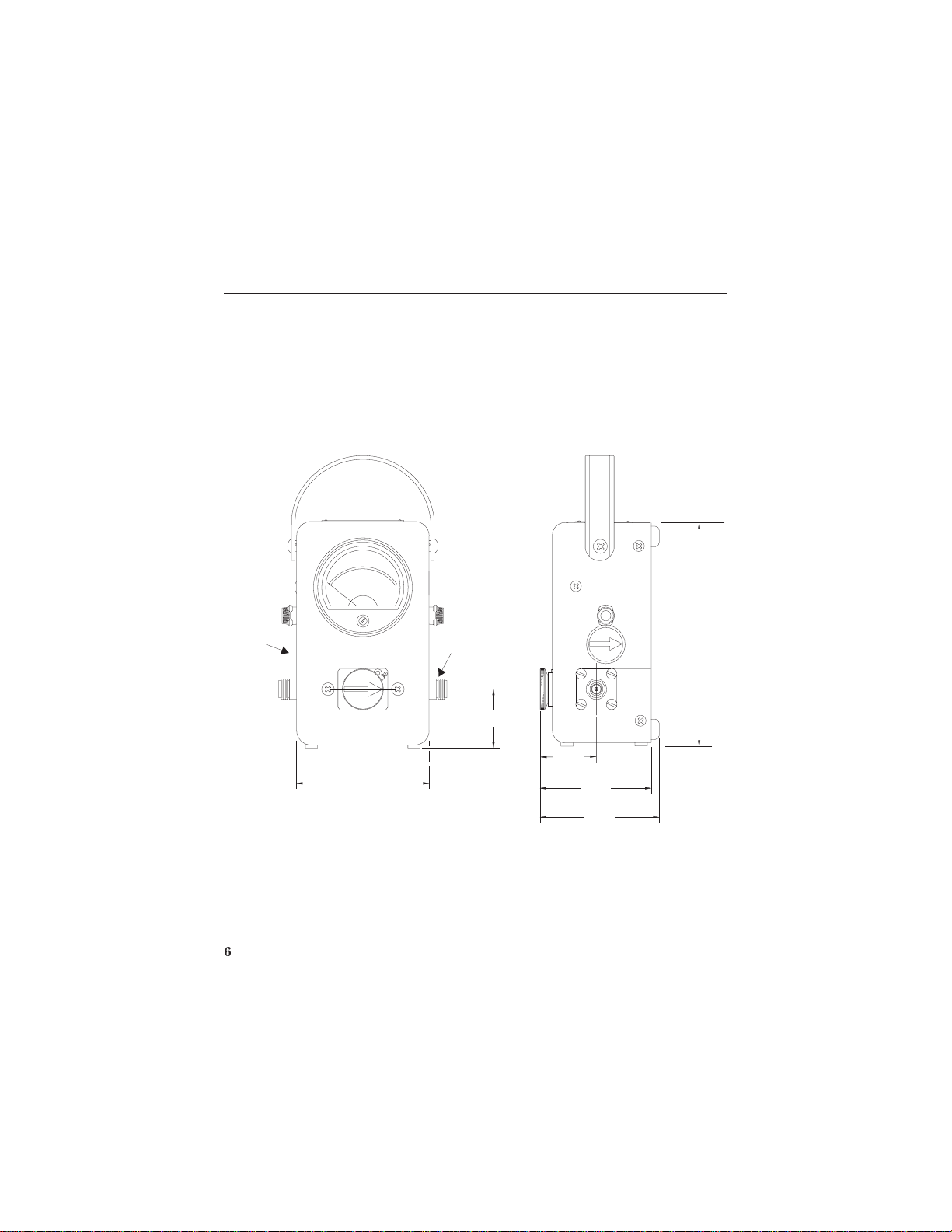
Model 43 Outline Drawing
Socket for
Extra Element
6
4"
(101.6mm)
Female "N" Q.C.
Connectors (2)
(Normally
Supplied)
1-3/4"
(44.5mm)
1-5/16"
(33.3mm)
(85.7mm)
3-3/8"
3-5/8"
(92.1mm)
6-7/8"
(174.6mm)
Page 21

Chapter 2
Theory of Operation
Travelling Wave Viewpoint
The best way to visualize the Thruline Wattmeter principle is from the
Travelling Wave viewpoint. In transmission lines, the voltages, currents,
standing waves, etc., on any uniform line section are the result of the
interaction of two Travelling waves:
s
The forward wave travels (and its power flows) from the source
to the load. It has RF Voltage Efand current Ifin phase, with E
/If=Z
s
The reflected wave originates by reflection at the load, travels
(and its power flows) from the load back to the source, and also
has an RF voltage Erand current Irin phase, with Er/Ir=Zo.
s
Note that each component wave is mathematically simple, and is
completely described by a single figure for power, for instance:
o.
f
Wf= Watts Forward = E
Wr= Watts Reflected = E
2
/Zo=I
f
2
r
f
/Zo=I
2
Zo=EfI
2
Zo=ErI
r
f
r
Zois the characteristic impedance of the uniform line, and simplifies matters
by being nearly a pure resistance, usually 50 ohms, for useful lines. The
main RF circuit of the Model 43 is a short piece of uniform air type line
section, whose Zois 50 ohms, in which accurate measurements may be made.
Coupling Circuit
The coupling circuit which samples the travelling waves is in the Plug-In
Element. The circuitry of the element and its relationship to the other
7
Page 22

Bird Model 43 Wattmeter
components of the Model 43 are illustrated in the Schematic diagram, figure
3.
Figure 3
Element
Schematic
Diagram
XMTR
or
LOAD
RF Coaxial Line
LOAD
or
XMTR
Directional Coupling
Detector Element
Diode
DC Contact
DC
Connector
Bypass
Meter
Energy will be produced in the coupling circuit of the element by both mutual
inductance and capacitance from the travelling RF waves in the line section.
The inductive currents will flow according to the direction of the travelling
waves producing them. The capacitive portion of these currents is inde-
pendent of the direction of the travelling waves. Therefore, assuming that
the Plug-In Element remains stationary, it is apparent that the coupling
currents produced from the waves of one direction will add in phase, while
those produced from the waves of the opposite direction will subtract in
phase. The additive or arrow direction is assigned to the forward wave.
The electrical values of the element circuits are carefully balanced and so
designed that the inductive current produced from the reverse wave will
cancel its portion of the capacitive current almost completely. The result is
a directivity always higher than 25 dB, which means that the element is
highly insensitive (nulled) to the reverse direction wave. By being highly
directional, the element is sensitive at either one of its settings, but to only
one of the two travelling waves which produce standing waves by interfer-
8
Page 23

Theory of Operation
ence. Thruline Wattmeter measurements are also independent of their posi-
tion along the standing waves.
Standing Wave Ratio vs Reflected/Forward Power Ratio
As mentioned above, the Thruline Wattmeter technique uses the Travelling
Wave viewpoint to measure most of the outstanding facts about transmission
line operation. Another widely used and related viewpoint, is the Standing
Wave one, which is quite elaborately developed both mathematically and in
existing equipment. This technique can be traced to the early development
of slotted lines as tools of exploration.
The slotted line is a standing wave instrument and emphasizes this view-
point. However, the slotted line is too long, too expensive if good, not portable,
and slow in operation. These objections increase rapidly as the frequency
drops below 1000 MHz. Whereas the Thruline Wattmeter is surprisingly
quick, convenient, and accurate by comparison. With the exception of phase
angle reflection (distance, load to minimum), it tells everything a slotted line
will.
The relationship between the Travelling Wave and the Standing Wave
viewpoints is given in most high frequency textbooks.
Load Power
Power delivered to and dissipated in a load is given by:
Wl= Watts into Load = Wf-W
r
Where appreciable power is reflected, as with an antenna, it is necessary to
subtract the reflected power from the forward power to get the actual load
power. This correction is negligible (less than one percent) if the load has a
VSWR of 1.2 or less. Good load resistors, such as Bird Termaline loads, will
show negligible or unreadable reflected power.
VSWR scales and their attendant controls for setting the reference point have
been intentionally omitted from the Model 43 for two reasons.
9
Page 24

Bird Model 43 Wattmeter
1. Why make something similar to a hypothetical dc volt-
ohm-meter with control pots for the voltmeter multipli-
ers? Even more complications arise when diodes at RF
are involved.
2. Experience using the Thruline Wattmeter for transmitter
tune-up, antenna matching, etc. (i.e., on operating prob-
lems), shows that the power ratioφis as useful in prac-
tice as the standing wave ratio p = VSWR.
A trial is suggested for a few days - forget VSWR and try thinking in terms
ofφ=Wr/Wfwhen the Thruline Wattmeter is used. It will be noted that
even without bothering to calculate the ratio exactly, the two meter readings
Wrand Wfgive an automatic mental impression which pictures the situation.
Thus, for an antenna matching problem, the main objective usually is to
minimize Wr. Anything done experimentally to this end is noted directly
when the Model 43 element is turned to the reflected position. Furthermore,
the ratio of readings, even if only mentally evaluated, is a reliable guide to
the significance of the remaining reflected power.
ρ
vs.φand Its Significance
Since there are definite simple relationships:
2
1
φ
+
p and
=
1
φ
−
between standing wave ratio p and the reflected/forward power ratioφ,
indicated by the Thruline Wattmeter, the latter may be conveniently used
to measure VSWR. The relationship is given in figures 4 and 5.
Note that whenφ= 10 percent, below which Wrwill appear insignificant and
may be hard to read, you are close to the commonly accepted lower limit p
= 2, below which improved antenna match becomes less and less worthwhile
in many systems. Experimentally, by using the Thruline Wattmeter, it can
L
p
φ
−
=
M
p
+
N
Where p VSWR
O
1
P
1
Q
and
=
W
r
=φ
W
f
10
Page 25

Theory of Operation
be readily shown that reducingφbelow 10 percent produces little gain in
the way of increased Wl. TV transmitter antenna lines, and VHF omnirange
transmitters are among those systems that require much lower levels of
reflected power but for reasons other than simple power transmission. Note
that in figure 4, the very small level of reflected power, i.e.,φ= 0.06 percent
corresponds to p = 1.05. While both forward and reflected power levels can
be measured with the same element, detection of reflected power is possible
down to aboutφ= 1 percent (p = 1.2), provided Wfapproaches full scale.
However actual measurement is possible only down to aboutφ= 5 percent
(p = 1.5). For more accurate measurements of reflected power levels, an
element rated at one tenth of the full scale power value of the element used
to measure forward power is recommended.
CAUTION
When making low reflection readings using a more sensitive
element, take care to insert the element so that it senses
reflected power only. Do not rotate the element in the socket so
that it is subjected to forward power. This can result in damage
to the Plug-In Element, the microammeter, or both.
Low reflection measurements may be extended below this with two elements.
Say 80 watts are available, and you have 100 watt and ten watt elements.
Measure Wfwith the 100 watt element. Remove the 100 watt element and
insert the ten watt element. The ten watt element must be inserted only in
the reflected direction, arrow toward transmitter. Insert and remove only
this way. Now read Wron the ten watt element.
In this case, measurement down to at least 0.5 watt reflected is possible,
which means to say:
05
.
φ= =
06% 116
..or close to or to roughly p
80
11
Page 26

Bird Model 43 Wattmeter
Percent Reflected Power VS. VSWR (1.0:1.3)
Figure 4
2.0
1.0
.9
.8
.7
.6
f
.5
.4
.3
.2
.1
.09
.08
.07
.06
PERCENT REFLECTED POWER—
.05
.04
Wr
f=¾ x 100 =——————————— x 100
Wf
REFELECTED POWER
FORWARD POWER
12
.03
.02
1.05 1.10 1.15
1.20
1.25 1.30 1.40
VSWR—r
Page 27

Theory of Operation
Percent Reflected Power VS. VSWR (1.0:8.0)
Figure 5
100
90
80
70
60
f
50
40
30
20
10
9
8
7
6
PERCENT REFLECTED POWER—
5
4
3
Wr
f=¾ x 100 =——————————— x 100
Wf
REFELECTED POWER
FORWARD POWER
2
1
12 3 8
4
56
7
VSWR—r
13
Page 28

Bird Model 43 Wattmeter
and detection of reflected power is possible down to about 0.1 watt.
.
01
0 00125 01% 106
φ= = =
.. .or close to or to roughly p
80
Caution is necessary in the above method and preferably it should not be
used with element ranges differing by more than 10 to 1 although 25 to 1
can be used with extreme caution. With elements available having ranges
down to one watt or less full scale, this method is usable with medium and
low power transmitters.
Measurement And Monitoring of Transmitter Power
The Thruline Wattmeter is useful for the continuous monitoring of transmit-
ter output and is also helpful for the continuous monitoring of reflected power,
for instance in checking intermittent antenna or line faults.
Like diode devices in general, the Model 43 indicates the carrier component
on amplitude modulation, with very little response to side band components
added by modulation.
Testing of Lines, Connectors, Filters, Etc.
The Thruline Wattmeter is highly useful for this purpose, and may be
employed in several ways.
1. VSWR (Insertion) orφ(Insertion) may be measured with
the line terminated in a good Termaline Load Resistor.
2. Attenuation (power lost by heat in the line) as well as
VSWR (Insertion) andφ(Insertion) may be measured by
inserting the unknown line between Thruline Wattmeter
units, or between two RF line sections using only one me-
ter and one set of elements (the end of the line to be ter-
minated in a good load resistor). This method applies
also to insertion between a Thruline Wattmeter and a
Termaline Absorption Wattmeter. Very small values of at-
14
Page 29

tenuation require allowance for normal instrument er-
rors. The correction may be determined by direct rigid
connection of the Thruline Wattmeter units, or of the
Thruline Wattmeter - Termaline Load combination, in cas-
cade. Slight juggling of the zero settings is permissible
for convenience in eliminating computation, provided read-
ings are being taken fairly well up on the scale.
3.
Attenuation By Open Or Short Circuit Method
clever by far than method (2) is one depending on the
high directivity (null balance) to which the Thruline Watt-
meter elements are held. They should, and do, exhibit
good equality between forward and reflected readings
when the load connector is open or short circuited. In
this condition,φ= 100 percent, the forward and reflected
waves being equal in magnitude, and p = infinity. Say
that this is checked on open circuit, and then a length of
line of unknown attenuation, also open circuited, is con-
nected to the load connector. The ratioφthen shown is
the attenuation in two passes along the line (down and
back).
Expressed in dB,
F
using the equation: N ,
G
H
dB
=
10log
W
W
r
f
Theory of Operation
. More
I
J
K
the dB figure may be compared with published data for line type and length
by remembering to halve NdBor to double the line length, because twice
the line length is actually being measured.
This measurement should be supplemented by one ofφ(Insertion), or at least
by dc continuity and leakage checks, since the attenuation measurement
alone can be in error from faults such as open or short circuits part of the
way down the line.
15
Page 30

Bird Model 43 Wattmeter
Open circuit testing is somewhat to be preferred to short circuit, since the
reference short (used to check equality initially) must be good, and because
the initial equality is somewhat better on open than on short circuit.
Again, for quite low values of attenuation, it is advisable to note exact
readings, or difference, on the initial equality check, and to allow for this
difference.
Frequency Response
The Plug-In Elements have a very flat frequency response over a frequency
ratio of more than 2-1/2 to 1. This characteristic provides a practically flat
response within the assigned frequency ranges for all the elements. An
illustrative set of curves for three elements of one of these frequency bands
is shown in figure 6. Notice that on the low power element, the fall-off above
and below the assigned frequency band is more pronounced than it is for the
high power element. The degree of drop in response varies progressively less
for each power level from low to high. For example, at 40 MHz, the 10C
element will typically read about 4 dB low which is about 40 percent of the
true value or 4 watts. The 100C will read only about 1 dB low or about 80
percent of the true value (80 W) and the 500C should read within the normal
five percent of full scale tolerance. These curves may be assumed to be about
typical for all of the band types (H, A, B, C, D, etc.) at their respective stated
frequencies.
Harmonics, or subharmonics, may be known to exist in the measured circuit,
outside of the element frequency band. If so, a rough approximation of the
response of the element to these harmonics may be made by the use of these
curves. The frequency ordinate to be read on the graph will be obtained by
proportioning the frequency of the element used with that of the one
illustrated. Interpolation of the curve values will give an approximation of
the extent to which these harmonic signals are being measured by your
element.
Nevertheless, the use of an element for direct power measurements outside
of its stated frequency range is not recommended. The responses given are
only typical, and are by no means guaranteed.
16
Page 31

Theory of Operation
Representative Frequency Response
Figure 6
-10 -5 0
-10 -5 0
Relative ResponseDB
-10 -5 0
20 40 60 80 100 200
Frequency InMegahertz
400
600
800
1000
10 C
Element
100 C
Element
500 C
Element
Impedance Mismatch
There may be cases where it is necessary to use the Model 43 on other than
the 50 ohm circuit for which it is designed. When using the Thruline
Wattmeter, you will be inserting a four-inch length of 50 ohm air line into
the circuit and therefore the load on the transmitter will be changed from
its original condition without the Thruline Wattmeter. If the reflected power
17
Page 32

Bird Model 43 Wattmeter
is less than 10 percent and the frequency is below 200 MHz, the four-inch
length will produce a mismatch that is not too serious. But going any higher
than these values, even if the transmitter is tuned up with the Model 43 in
place, the load impedance will be very different after the Thruline Wattmeter
is removed.
The Model 43 in a 50 ohm line will indicate zero reflection when the load,
at its load connector, is 50 ohms, pure resistive. However, even an ideal
condition on a 70 ohm line on the load side of the wattmeter will show three
percent reflected power and cause a VSWR of 1.4 to 1.0. (If Thruline
Wattmeter is 50 ohms and load is 70 ohms resistive, VSWR in the wattmeter
is 70/50 = 1.4.) The Thruline Wattmeter could also show this same reflected
percentage with a 50/1.4 = 35.7 ohms pure resistive load which could exist
with 10 percent reflected power on the 70 ohm line (VSWR = 2). From this
you can see that the 70 ohm line could actually have as much as 10 percent
reflected power and a VSWR = 2 even though the Thruline Wattmeter
indicates only three percent reflected power, and a VSWR = 1.4.
It should be especially remembered that with 70 ohm lines it is most
important to measure the reflected power and subtract it from the forward,
because of this factor being so much more critical here than with a 50 ohm
line.
18
Page 33

Chapter 3
Installation
Portability
The Model 43 is a portable instrument, and the housing is not designed for
fixed mounting (see Outline Drawing, page 8). A strap is provided for carrying
purposes.
While transporting the Thruline Wattmeter, it is best to reinsert the original
dust plug, or a Plug-In Element with the arrow pointed upward, in the
measuring socket, and secure with the catch. This will shunt the meter circuit
and serve to protect the meter by dampening needle action during handling
or shipping. Also, secure spare Plug-In Elements in their receptacles with
the pivoting knob clamps; just insert the element to seat and twist the knob
one-quarter turn to hold. Handle the Plug-In Elements with care at all times.
Calibration could be disturbed if they are dropped.
Connections
WARNING
Leaking RF energy is a potential health hazard. Never attempt
to connect or disconnect equipment from the transmission line
while RF power is being applied. Severe burns, electrical shock,
or death can occur.
Insert the Model 43 Wattmeter in coaxial transmission lines of 50 ohms
nominal impedance. It is indifferent to which respective side the power source
and the load connections are made. If cables other than 50 ohm type are
used, a mismatch will occur causing inaccuracies in readings. However, if a
mismatch cannot be avoided, the results may be calculated per the Impedance
Mismatch paragraph. It is strongly advised that this condition be avoided.
19
Page 34

Bird Model 43 Wattmeter
The Model 43 is normally supplied with two Female N type connectors which
are of the Bird Quick-Change design. Other QC connectors are available,
refer to the Replacement Parts List in the Maintenance Chapter.
Follow these steps to change the QC connectors.
1. Remove the four 8-32 pan head machine screws from the
corners of the connector flange.
2. Pull the connector straight out.
3. Reverse this procedure to attach connector, making sure
the center contact pin aligns properly with the socket.
Remote Installation
The RF line section can be removed from the meter housing for remote
installation. To remove the line section from its housing:
1. Unscrew the four 8-32 flat head machine screws holding
the back cover.
2. Grasp the cover by the side filler tabs and pull directly
backwards. The back cover assembly will come off with
the speed nuts remaining attached.
3. Remove the two 10-32 oval head machine screws on the
front of the housing.
4. Slide the line section backwards out of the housing. Do not
loosen the two oval head screws on the sides of the hous-
ing in line with the meter. These hold the meter support-
ing shock ring in place.
5. Substitute the cable which attaches the line section to the
meter with a sufficient length of cable to make the re-
mote installation.
6. To replace the RF line section, reverse the above listed pro-
cedures.
It may be desirable to have two or more line sections permanently installed
in continuous operating equipment. In this case, one set of elements and one
20
Page 35

Installation
meter may be used to measure several RF transmission lines without
interruption of RF lines for insertion of the Thruline Wattmeter. Additional
RF line sections are available (see figure 7).
The RF line section of the Model 43 lends itself very readily to panel type
mounting. A layout for the panel mount cut is given in figure 8. The thickness
of the panel should be about 1/4 inch. On panels less than this, build up the
thickness with pads or washers to achieve a flush-face mounting. Cable
connections are simplified because the RF line section may be mounted in
any convenient direction. Attach the line section so that the finger catch is
in the most accessible position.
21
Page 36

Bird Model 43 Wattmeter
Figure 7
RF Line
Section
#10-32 x 9/32 DEEP TAP
TWO HOLES
D-C CABLE, RG-58/U(W-403)
ORIENT TO SUIT
FEMALE "N" CONNECTORS
OR AS OTHERWISE SPECIFIED
2-1/8"
1-1/2"
3-13/16"
5-1/8"
PLUG-IN ELEMENT
DETERMINES POWER &
FREQUENCY RANGE
1-1/4"
SQUARE
7/8"
J-411
P-401
1-3/64"
5/8"
17/64"
2-5/16"
Figure 8
Panel Cut for
Mounting RF
Body
22
1/8" Rad or
1/8" x 45° chamfer
13/64 (.203) Diadrill
and countersink for
#10-32 FHMS-two holes
2.125
1-17/64
1-33/64
Page 37

Chapter 4
Operating Instructions
Zero Adjust
The meter should be checked for zero set under no power conditions. With
no power applied the meter pointer should set exactly on zero. If adjustment
is required, turn the adjustment screw until the pointer is set at zero (refer
to figure 9).
Figure 9
Zero Adjust
Zero Adjust Screw
WARNING
When operating this equipment in conjunction with RF power of
200 watts or higher, the potential of the center conductor of the
RF line section will be 100 volts or higher. Do not contact the
center conductor. If cleaning becomes necessary, shut off the RF
power.
23
Page 38

Bird Model 43 Wattmeter
General
Measurements are made by the insertion and operation of the Plug-In
Elements. The elements determine the power range to be read on the meter
scale, and the major marking (e.g. 50 W, 100 W, etc.) are the full scale power
value for the element. Elements are also marked for frequency range. The
transmitter frequency must be within the band of the element used. Refer
to the Bird Catalog for a large selection of elements.
Refer to the Frequency Response paragraph for frequency band flatness and
performance of the elements outside of their stated frequencies. Elements for
additional ranges (power or frequency) may be ordered without returning the
Model 43 for calibration, since the RF bodies and meters are standardized,
and are designed for a wide range of coaxial transmission power value and
frequencies.
The arrow on Plug-In Elements indicate sensitive direction; i.e., the direc-
tion of power flow which the meter will read. Arrow and Reverse are
directional terms used in reference to the Thruline Wattmeter Element, and
mean respectively the sensitive and insensitive directions of the element.
Rotate the element to reverse the sensitive direction. Forward and Re-
flected are directional terms used in reference to the source-load circuit. The
transmitter may attach to either connector of the wattmeter. It makes no
difference which external RF connection is selected, since the elements are
reversible and the RF circuit is symmetrical end for end. Refer to figure 10.
The Thruline Wattmeter used with a Termaline Load Resistor of proper
power rating forms a highly useful absorption wattmeter. With the arrow
set toward the load, it is unnecessary to reverse the element, because the
reflected power should be negligible.
24
Page 39

Figure
10
Direction of
Element
Operating Instructions
ToLoad To Transmitter
Forward Power Measurement
ToLoad ToTransmitter
Normal Operation
Reflected PowerMeasurement
1. Insert the appropriate element in the socket of the line sec-
tion.
2. Rotate the element so that the arrow on the nameplate
is pointed away from the RF source for forward power
and towards the source for reflected power.
3. Turn on the RF source.
4. Read the power level indicated on the appropriate meter
scale.
In cases where readings are being made when the meter unit is connected
to an auxiliary RF line section, always remove any measuring element from
the unused RF line section. Otherwise, the dc circuit will be unbalanced or
shorted according to the arrow position of the other element, causing
inaccurate or no indication on the meter.
For the convenience of users, a set of VSWR conversion nomographs is
included in this instruction book. With these charts, VSWR may be directly
determined from forward and reflected power values read from the Thruline
Wattmeter.
When a Model 43 is used to match a load to a transmitter and a good match
is obtained, removing the instrument will not cause any change in the
25
Page 40

Bird Model 43 Wattmeter
conditions, since a good 50 ohm load can be placed at the end of a 50 ohm
transmission line of any length without altering conditions at the transmitter.
Using the VSWR Nomograph, determine the intersection of the forward and
reflected power values. The slanted line passing closest to this point indicates
the VSWR.
What happens when the load is not well matched, like an antenna with a
VSWR of 1.5 or 2.0? Since the length of line between a mismatched load and
the source transforms the impedance of the load as seen at the source, line
length now becomes critical. If the adjustments for maximum power transfer
were made with the Model 43 in place, removing it shortens the line by four
inches, plus two connectors. This still is no cause for concern at low frequen-
cies where four to five inches is a small fraction of a wavelength. At higher
frequencies; e.g., above 100 MHz, power output and frequency of the source
may be affected.
It is a principle of transmission line theory that the impedance is identical
on either side of a 1/2 wavelength. In order to duplicate the conditions in
your transmission line with the Model 43 either in or out of the line, it is
only necessary to insert or remove a 1/2 wavelength.
This is easily done by making up a length of cable which, when added to
the Thruline Wattmeter, equals 1/2 wavelength at the frequency of measure-
ment. If more than one frequency is involved, a separate cable is needed for
each frequency.
26
Page 41

Operating Instructions
VSWR Conversion Nomograph
Figure 11
500
1.05
1.06
1.07
1.08
1.09
1.10
1.12
1.14
1.16
1.20
1.25
1.3
1.4
1.5
1.6
1.8
2.0
2.5
3.0
4.0
10
VSWR
Reflected Power
Forward Power
Reflected Power
Forward Power
1
1+
300 400
100 150 200
50
30 40
25
20
15
10
5.0
4.0
3.0
2.5
2.0
1.5
1.0
FORWARD POWER - WA TTS
VSWR=
18
16
14
20
8
12
10
4
6
2.0
1.8
1.6
1.4
.8
1.2
1.0
.4
.6
0.5
.2
REFLECTED POWER - WATTS
27
Page 42

Bird Model 43 Wattmeter
VSWR Conversion Nomograph
Figure 12
500
300 400
1.03
1.04
1.05
1.06
1.07
1.08
1.09
1.10
1.12
1.14
1.16
1.20
1.25
1.3
1.4
1.5
1.6
1.8
2.0
2.5
3.0
4.0
10
100 150 200
50
30 40
25
20
10 15
FORWARD POWER - WA TTS
5.0
4.0
3.0
2.5
2.0
1.0 1.5
28
VSWR
.9
.8
.7
1.0
.4
.6
.5
.2
.3
.1
.09
.08
.07
.06
.05
.04
REFLECTED POWER - WATTS
.02
.03
0.5
.01
Page 43

Operating Instructions
Cable Wavelength Matching Graph
Figure 13
36
32
28
24
C
A
B
L
E
20
L
E
N
G
T
H
16
I
N
C
H
E
S
12
8
MEGAHERTZ (600) (700) (800) (900) (1000)
I
N
C
H
E
S
(10)
(9)
(8)
(7)
(6)
(5)
4
0
200 300 400 600
500
(4)
700100
FREQUENCY (MEGAHERTZ)
29
Page 44

Bird Model 43 Wattmeter
Notes:
1. Physical cable length shown in inches is measured from
end to end of outer conductor of connectors (TNC and N
Male connectors), except for cables with UHF or Mini-
UHF plugs where the cable length is measured from tip
to tip of the center pins.
2. Dimensions shown are for
solid
polyethylene cable (e.g.
RG-58C/U, RG-8/U) which has 66 percent the velocity of
propagation relative to air. If so-called RG-58 type or
RG-8 type cables (which often contain foam polyethyl-
ene) are used, the dimensions in the graph must be mul-
tiplied by that cables relative velocity (say 79 percent)
divided by 66 percent (i.e. by a factor of 79% ÷ 66% =
1.2).
30
Page 45

Chapter 5
Maintenance
This chapter contains operator maintenance instructions, troubleshooting and
parts information.
The rugged and simple design of the Model 43 Wattmeter requires minimum
routine maintenance.
Troubleshooting
The following table contains troubleshooting information for problems which
can occur during normal operation. Locate the problem, review the possible
cause, and perform the corrective action listed.
Only those functions within the scope of normal maintenance are listed. This
manual cannot list all malfunctions that may occur, or all corrective actions.
If a malfunction is not listed or not corrected by the listed corrective actions,
notify a qualified service center.
31
Page 46

Bird Model 43 Wattmeter
Problem Possible Cause Corrective Action
No meter indication
Intermittent or inconsistent meter
readings
High VSWR or
Reflected Power
No RF power Check RF source
“Arrow” on Plug-in
element pointing in wrong
direction
No pick-up from dc
contact finger
Open or short circuit in dc
meter
Meter burned out or
damaged
Sticky or defective meter Replace or return
Dirty dc contact on
elements
Faulty transmission line or
antenna
Bad load or poor
connectors
Shorted or open
transmission line
Foreign material in line
section or in RF connector
bodies
Reposition element
Adjust per the Contact
Adjustment paragraph
Replace defective cable
(RG-58/U)
Replace or return
wattmeter to the factory
for meter replacement and
recalibration.
wattmeter to the factory
for meter replacement and
recalibration
Clean per cleaning
paragraph
Inspect line
Replace load, antenna or
connectors
Service or replace line
See Cleaning paragraph
Cleaning
If any of the contacts or line connectors become dirty, they should be cleaned
with a good contact cleaner or dry cleaning solvent on a cotton swab stick.
Clean all contact areas and especially the exposed faces of the Teflon
insulators.
32
Page 47

Maintenance
It is important to keep the following surfaces clean:
s
Socket bore
s
Element body circumference
s
Bottom rim of the socket in the line section
s
DC contacts on the element
The outside surface of the meter housing can be cleaned with a soft cloth
dampened with a mild detergent solution. Do not wipe the meter glass with
a dry cloth, a static charge could develop causing an erroneous indication on
the meter.
Preventive Maintenance
The element socket should be kept plugged as much as possible to prevent
the intrusion of dust, and to prevent damage to the meter. Use the dummy
plug provided, or use an Element. When an Element is used for this purpose,
use the highest power element available. It should be positioned with the
arrow pointing upwards (midway between the FWD and RFL measuring
positions). This protects the meter and will not expose the element diode to
dangerous potentials if the RF line section should be energized.
Line Section Care
If there is any evidence of contamination inside the RF line section, the
reachable portions should be cleaned and the interior carefully blown out.
Under no circumstances attempt to remove the RF center conductor. It is
tightly frozen in place and any attempt to remove it will ruin the assembly.
Keep all connections tight, and keep the nut of the meter cord plug turned
tight on the line section dc jack. This connection may often be serviced by
simply loosening the nut of the dc plug, swinging the body several times
through a fraction of a turn, and retightening the knurled nut securely.
Contact Adjustment
In cleaning the socket bore, the operator should be careful not to disturb the
spring finger of the dc contact. It is important that the operating position of
33
Page 48

Bird Model 43 Wattmeter
this part be properly maintained. If the spring finger of the dc contact
requires adjustment, it may be done manually if done carefully. The button
must be positioned far enough out to maintain good contact with the element,
but not so far as to interfere with easy entry of the element body. The dc
jack, with spring finger, may be removed for access by:
1. Unscrewing the two 4-40 fillister head machine screws
which fasten it to the side of the RF line section.
2. Retract its assembly, watching carefully so as not to lose
the small Teflon positioning bead that straddles the base
of the phosphor bronze spring and nests in a counterbore
on the side of the RF body.
3. Replace the assembly (be sure that the bead is again prop-
erly inserted) and the two screws previously removed.
Calibration Checks - Thruline Wattmeter vs
Termaline Wattmeters
It is recognized that calibration of absorption wattmeters is difficult and
likely to be inaccurate unless comparison is made with a transmission,
through, type of standard. With the Thruline Wattmeter being of such type,
a natural question is: Can a Thruline Wattmeter be used to check or
recalibrate absorption wattmeters, such as the Bird Electronic Corporation
Termaline Wattmeter, when both are rated at ±5 percent of full scale
accuracy? The main question is one of exact power calibration.
The answer is a qualified yes, although with both instruments being about
equally old and known to be undamaged, there is not too much reason to
prefer either on probable accuracy. The edge is somewhat in favor of the
Thruline Wattmeter because each element covers a range of only 2-1/2 to 1
in frequency and will be flatter originally over this range than the Termaline
Wattmeter can be held initially over its very much wider, 16.7 to 1, frequency
range. Also the Thruline Wattmeter will probably exhibit smaller changes
with time, because of the narrower frequency range. It is simpler in general
design and easier in function (does not have to serve as a power load), and
it does not become heated in operation.
34
Page 49

Maintenance
Certainly if the absorption wattmeter has gone for years since its last
calibration, or is reasonably suspected of inaccuracy, it may well be calibrated
against the Thruline Wattmeter as the standard. Rather than use correction
factors, one can, with Termaline Wattmeters, make use of the calibration
adjustment screws used in factory calibration. These are concealed and not
mentioned in the instruction book to discourage tampering. Consult the
factory before changing the adjustment.
If such calibration is undertaken, care and thoroughness are advised.
Model 43 Replacement Parts List
Item Qty. Description Part Number
1 1 Housing Assembly 4210-018
2 1 Cover Assembly 4210-005-1
3 1 Line Section Assembly 4230-018
4 1 Carrying Strap 8580A003
5 1 Dust Plug, Aluminum 3610-031
6 1 DC connector Assembly 4230-010
7 1 Microammeter 2080-002
8 1 DC Connector 7500-076
9 1 Coaxial Cable Assembly 4220-097-1
10 2 Turnbutton 4300-015
11 2 Spring Washer 5-1144-1
12 8 Rubber Stem Bumper 5-1388
13 2 Pushnut 5-1076-1
14 1 Replacement Meter Kit consisting of:
1 Meter
1 Cable Assembly
3 Bumper Feet
15 2 RF Connectors *See List on
8-000
2080-002
4220-097-1
5-040
next page
35
Page 50

Bird Model 43 Wattmeter
*Available “QC” Type Connectors
Connector Part Number Connector Part Number
N-Female 4240-062 LT-Female 4240-018
N-Male 4240-063 LT-Male 4240-012
HN-Female 4240-268 C-Female 4240-100
HN-Male 4240-278 C-Male 4240-110
LC-Female 4240-031 UHF-Female 4240-050
LC-Male 4240-025 UHF-Male 4240-179
BNC-Female 4240-125 TNC-Female 4240-156
BNC-Male 4240-132 TNC-Male 4240-160
SMA-Female 4240-336 SC-Female 4240-090
SMA-Male 4240-334 Mini UHF-Female 4240-346
7/8" EIA 4240-002 7/16" IEC (Plug)
Type 169-4
1-5/8" EIA Fixed 4240-096 1-5/8" EIA Swivel 4240-208
7/16" IEC (Jack)
Type 169-4
4240-344 Open Term.
#10-32 Nut
4240-363
4240-080
36
Page 51

Maintenance
Exploded View Of The Model 43
Figure 14
37
Page 52

Bird Model 43 Wattmeter
Model 4431 Thruline Wattmeter
The Model 4431 RF Sampling Wattmeter is essentially the same as the Model
43 Thruline Wattmeter described in this instruction book except for the extra
provision of the adjustable RF signal sampler probe.
Theory of Operation
The RF sampler, as its name implies, provides a low level signal or sample
of the energy being transmitted through the line section of the wattmeter.
This signal is available at a Female BNC connector located on the right side
of the meter housing, labeled RF SAMPLE, and the level of this signal can
be varied by means of the control knob located on the front of the meter
housing. This adjustment is accomplished by means of mechanical linkage
connecting the sample adjustment (control) knob to the RF probe, so that
turning the knob varies the proximity of the RF probe to the center conductor
of the line section. Placing the probe closer (clockwise) to the center conductor
increases the coupling and the signal level at the RF sample port, and moving
the RF probe away from the center conductor (counterclockwise) decreases
the coupling. Refer to table 1 for an approximate guide for the levels of
coupling, and for a note on the maximum suggested adjustment of the
sampler. In the operation of the unit, the sampler output may be fed to any
suitable RF signal monitoring device; i.e., frequency counter, spectrum ana-
lyzer, oscilloscope, etc.
38
Page 53

Maintenance
Table 1
Model 4431 Coupling Data
Maximum Counterclockwise
Frequency (MHz) Sensitivity
(Fully Clockwise)
269
10 57
25 46
50 42
75 39
100 36
200 31
300 38
400 34
500 30
600 29.5
700 29
800 28.5 36
900 28 35.5
1000 35
4 Full Turns
From Max.
Position
(Approximate dB
attenuation)
7 Full Turns
From Max.
Position
(Approximate dB
attenuation)
Note: It is important to decouple the RF sampler as indicated above for
frequencies above 200 MHz. The basic specifications of this instrument will
be maintained with the above settings for the RF sampler. Decouple or turn
counterclockwise beyond the above settings as much as possible, when
possible.
39
Page 54

Bird Model 43 Wattmeter
Operation
The basic operations and maintenance procedures for the Model 4431 are
the same as those of the Model 43 as described in this instruction book.
Maintenance
The maintenance procedures for this model are essentially the same as for
the Model 43 except for the inclusion of the variable probe equipment. It is
not recommended that user make repairs on the probe assembly. If the
sampler malfunctions, we suggest the unit be returned to the factory. If for
a particular urgency, the user wants to make field replacement of the probe
assembly themselves, proceed as follows:
1. To reach the probe, remove the four 8-32 x 3/8 inch Phil-
lips flat head screws on the sides of the case near the
back.
2. Grasp the back cover firmly, by the tabs behind the line
connectors, and pull straight backward to remove the
back cover.
3. Use a 1/16 hex socket Hex wrench to loosen and remove
the small coupling control knob on the front of the watt-
meter, just above the Plug-In Element socket.
4. Remove the two 8-32 x 1/4 inch pan head screws fasten-
ing the guide and movable plate assembly to the back of
the line section.
5. Restore the control knob to the front of the shaft tempo-
rarily, then rotate the shaft counterclockwise until the
threaded collar is free of the screw shaft and pull the
movable probe plate straight out of the pin and guide
bushing.
6. Unscrew the 5/8 hex instrument nut on the BNC connec-
tor (outside) and pull the sampler connector inside the
case. The probe plate assembly, P/N 4431-003, is now re-
leased and may be replaced in its entirety.
40
Page 55

Maintenance
7. The sampler cable (RG-58/U) solid wire center conductor
is soldered to the rear stub of the probe piece itself. The
cable is secured to the side sleeve of the probe with the
same washer and screw parts used in the dc connector
plug assembly, P/N 7500-076. It may be removed by un-
screwing the threaded sleeve washer, 3/8 hex head, un-
soldering the lead tip and pulling out the cable. The
probe assembly is formed into the socket and is not re-
placeable.
8. Replace by carefully reversing the above procedure.
+
Note - When inserting the threaded control
bushing, be sure the alignment pin is properly
positioned.
Model 4431 Replacement Parts List
Item Qty. Description Part
Number
11
2
3
4
5
6
7
* Connector parts for probe sleeve
Modified housing (instead of 4210-018) 4431-011
1
Guide plate assembly 4431-002
1
Movable plate assembly 4431-003
1
Line section assembly (Instead of 4230-018) 4431-004
1
RF cable sampler assembly consisting of:
1 BNC connector, Female
1 RF cable - RG58/U
1 BNC connector eyelet
1 Washer*
1 Wedge*
1 Seal*
1 Screw*
1
Sampler control knob 5-1193
1
DC meter cable (Instead of 097-1) 4220-097-8
5-953
5-773-1
5-414-1
7500-074
7500-080
7500-081
7500-082
41
Page 56

Bird Model 43 Wattmeter
Series 4520 Thruline Wattmeters
The Series 4520 RF Thruline Wattmeter units are essentially the same as
the Model 43 Wattmeter, in that their electrical components and performance
characteristics are alike. These models are panel mounted for rack-type
installation instead of the all purpose portable housing of the Model 43
Wattmeter. Except for the Model 4527, which has an added feature of a
Female BNC RF Sampler output connector on the panel, the data and
operating instructions contained in this instruction book are applicable to
the Models 4521/22/23/25/26/27 in all respects, except as explained in the
following:
These units are intended for fixed installation, generally in rack mounts
requiring 19 inch panels. According to each of the model types concerned,
the various panels are punched out for the component arrangements involved.
The first line of the Replacement Parts List attached, lists the panel styles
for the respective Models 4521, 4522, etc. The remainder of this list carries
the replaceable items for each model. Only those items that are referred to
in this attached parts list, apply herein. The schematic diagram figure in
this instruction book is not applicable to these units.
Installation
Four 12-24 machine screws fasten the wattmeter panel in the selected
position on a relay rack, using the pattern of tapped holes regularly provided
in standard racks.
1. Choose a location for easy reading and operation of the
wattmeter; try to place it where the coaxial cable lengths
will be short and may be installed without sharp bends.
2. Avoid the use of angles and adapters.
3. Ensure all cable plugs and connectors are screwed on se-
curely.
42
Page 57

Maintenance
Theory of Operation, Operating Instructions and Maintenance
Sections
Although the physical configuration of these models is different, the provi-
sions in these sections of the Model 43 Instruction Book are fully applicable.
The Model 4527 is electrically identical to the Model 43 in every way except
for having an RF sampler port. The RF sampler port provides a low level
signal or sample of the energy being transmitted through the line section of
the wattmeter. This signal is available at a Female BNC connector located
on the right side of the panel, labeled RF SAMPLE.
Series 4520 Replacement Parts List
Item Qty. Description Part Number
1 1 Mounting panel
(Comprises: M=meter, E=element socket,
S=switch
Model 4521 (1M, 1E)
Model 4522 (1M, 2E, 1S)
Model 4523 (1M, 1E)
Model 4525 (1M, 1E)
Model 4526 (2M, 2E)
Model 4527 (2M, 2E)
2 1 Line section assembly
Model 4521/23/25
Model 4522/26
Model 4527
3 2 RF connectors See Model 43
4521-002
4522-006
4523-002
4525-002
4526-004
4527-005
4230-018
4522-002
4527-002
Replacement
parts list
43
Page 58

Bird Model 43 Wattmeter
Item Qty. Description Part Number
4
5
6 1 Switch control knob (Model 4522 only) 5-709
7 1 Plug connector
8 1 Rotary Switch (Model 4522 only) 5-634
9
10 1 RF cable assembly (Model 4257 only) 4430-002
DC connector assembly
1
Model 4521/23/25
2
Model 4522/26/27
Microammeter
1
Model 4521/22/27
1
Model 4523
1
Model 4525
2
Model 4526
Model 4521/23/25
Model 4522/26/27
Cable assembly
1
Model 4521/25 (16"L)
1
Model 4522 (Harness)
1
Model 4523 (16.5"L)
2
Model 4526/27 (16"L)
4230-010
2080-002
2150-015
2080-005
2080-002
7500-076
4220-097-5
4522-013
4523-003-1
4220-097-5
Model 4305A Thruline Wattmeter
The Model 4305A Thruline RF Directional Wattmeter is similar to the Model
43 except for the following items:
1. The housing assembly for the Model 4305A is different
from the Model 43. The overall physical dimensions of
the Model 4305A housing are 4-5/16"L x 4"W x 6-7/8"H
including element and bumper feet (110 x 102 x 175
mm). The weight, including the element, is 3-1/4 lb (1.5
kg).
44
Page 59

Maintenance
2. The line section has higher power capability and is larger,
being 1-5/8 inch in diameter instead of 15/16 inch as in
the Model 43, but this is not externally visible.
The Theory of Operation, and Maintenance Sections for the Model 43 are all
appropriate to the Model 4305A except for changes mentioned previously.
The Model 4305A Thruline Wattmeter does not have provisions for holding
spare elements in the sides of the housing.
Model 4305A Replacement Parts List
The following part numbers differ from those for the Model 43 Parts List.
Item Description Part Number
1 Housing assembly 4305A003
2 Cover assembly 4305A002
3 Line section assembly 4305-005
Model 4330 Thruline Wattmeter
The Model 4330 is very similar to the Model 43 and all the instructions and
provisions apply except as outlined below:
1. The Model 4330 is a low power indicating device with
full scale direct reading levels of 200 and 800 milliwatts.
2. This model uses special 0.2 and 0.8 watt dual-range ele-
ments that cover frequency ranges from 60 to 2300 MHz.
Standard higher power elements must
the Model 4330.
With these low power type elements, the discrete frequency band widths are
considerably less than the usual 2.5:1 ratio for standard higher power
elements. These band widths (ratios) vary, but tend to be broad in the middle
frequencies of the overall range and becomes narrow at the ends. Likewise,
the relative response fall off beyond the stated bands will have to be
considered as somewhat greater than depicted on the 10W element curve.
not
be used with
45
Page 60

Bird Model 43 Wattmeter
To maintain accuracy, it is important to have operating frequencies within
those stated.
The elements for the Model 4330 have a dual power range. The slide switch
on the face of the element is moved sideways to select either 800 mW or 200
mW full scale deflection as indicated by the element nameplate. The scales
on the meter dial coincide with the position selected. For protection of the
meter, always select the higher value first. Do not switch to the lower position
when a higher power is indicated in the direction selected.
The following parts are applicable to the Model 4330 and are different from
those listed for the Model 43. All other parts not listed here are applicable.
Model 4330/31 Replacement Parts List
Item Description Part Number
1
Housing assembly 4330-004
2
Microammeter, 10µA full scale, 3-1/2"
2160-027
rectangular
3
Meter cable assembly 33" cable e/w
4220-097-12
spade lugs and dc connector
Model 43P Peak Wattmeter
The Bird Model 43P Thruline Wattmeter is capable of measuring peak power
in AM, SSB, and certain limited pulse applications. It also possesses the
Model 43s ability to measure CW power (no amplitude modulation) with just
the press of a button.
No special elements are required for peak power measurements. However,
element power rating must match the peak power to be measured. For
example, if power output peaks of 1000 watts are to be measured, a 1000
watt element must be used in the line section port.
46
Page 61

Maintenance
Model 43P Specifications
RF Frequency Range 0.450-2700 MHz. depending on element selected.
RF Power Rating 100 mW to 10kW, depending on element selected.
Accuracy
When measuring rectangular pulse power, the following parameters must
be observed:
Duty cycle - 2% minimum
Rep. rate - 100 pps minimum
Pulse width - 200 µsec. minimum
Power Requirement (2) 9V alkaline batteries (NEDA 1604)
Battery Life 48 hours typical
CW mode ±5% of full scale
Peak mode ±8% of full scale
Operation
There is a PUSH ON/PUSH OFF switch on the right side of the meter
housing as you face the unit. To read peak power:
1. Push the switch in.
2. Notice that the red LED is lit. The unit is now ready to
indicate peak power.
To read CW power (no AM modulation):
1. Push the switch again to the OFF position.
2. Notice that the red LED is no longer illuminated. The
unit will once again function to indicate CW power.
Peak Detector Response
The electrical time constant of the peak detector circuit is set at one second,
although the actual response time may be slightly longer than this due to
meter damping. Therefore, a short delay may be noticed between the time
that the transmitter is energized, and the meter reading stabilizes. This delay
47
Page 62

Bird Model 43 Wattmeter
will also be noticed upon transmitter de-energization as the meter needle
sweeps back to zero. Also, the meter reading may be expected to waver
approximately 2-3 minor scale divisions when voice modulation is used as
the peak detector attempts to follow peak power variations associated with
voice modulation.
Model 43P Peak Calibration
If it is felt that the peak readings are questionable, or for any reason
recalibration is required, proceed as described.
Remove the rear cover, follow these instructions.
1. Remove the four 8-32 Phillips flat head screws that se-
cure the rear cover. There are two on either side of the
meter housing.
2. Pull the cover straight off.
Refer to figure 15 for the following calibration instructions:
1. Insert the Model 43P between an RF (CW) signal source
and a 50 ohm load.
2. Insert an element for the appropriate power and fre-
quency range into the Model 43.
3. Turn the element in the direction to read forward power.
4. Place the mode switch, on the side of the Model 43P, in
the CW position (LED off).
5. Turn on the signal source.
6. Adjust power to give a stable reading on the Model 43P
Wattmeter in the upper half of the scale.
7. Switch to the PEAK mode (LED on).
8. The RF power reading should remain the same. If it does
not read the same, adjust potentiometer (R9 -top center
of the PC board) until the PEAK reading is the same as
48
Page 63

Maintenance
the CW reading. When the CW and PEAK readings are
the same, calibration is complete.
9. Replace the back cover, using the four 8-32 Phillips flat
head screws.
Maintenance
Maintenance of the Model 43P in general will be the same as for the Model
43 except for battery replacement.
If the unit does not function properly in peak mode, or calibration cannot be
achieved, the batteries may be low. Replace the batteries with new ones,
preferably alkaline or lithium type. The batteries fit very tightly in their
retaining clips and may have to be pried out one at a time (refer to figure
15).
Figure 15
Model 43P
+R9-
Battery
Serial No.
Battery
49
Page 64

Bird Model 43 Wattmeter
Customer Service
Any maintenance or service procedure beyond the scope of those provided in
this section should be referred to a qualified service center. Bird Electronic
Corporation maintains a complete repair and calibration facility at the
following address.
Service Group
U.S.A. Sales and Service
Bird Electronic Corporation
30303 Aurora Road
Cleveland (Solon), OH 44139-2794
Phone: (440) 248-1200
Fax: (440) 248-5426
Sales Offices
For the location of the sales office nearest you, give us a call or visit our
Web site at:
http://www.bird-electronic.com
50
Page 65

Limited Warranty
All products manufactured by Seller are warranted to be free from defects
in material and workmanship for a period of one (1) year, unless otherwise
specified, from date of shipment and to conform to applicable specifications,
drawings, blueprints and/or samples. Sellers sole obligation under these
warranties shall be to issue credit, repair or replace any item or part thereof
which is proved to be other than as warranted; no allowance shall be made
for any labor charges of Buyer for replacement of parts, adjustment or repairs,
or any other work, unless such charges are authorized in advance by Seller.
If Sellers products are claimed to be defective in material or workmanship
or not to conform to specifications, drawings, blueprints and/or samples,
Seller shall, upon prompt notice thereof, either examine the products where
they are located or issue shipping instructions for return to Seller (transpor-
tation-charges prepaid by Buyer). In the event any of our products are proved
to be other than as warranted, transportation costs (cheapest way) to and
from Sellers plant, will be borne by Seller and reimbursement or credit will
be made for amounts so expended by Buyer. Every such claim for breach of
these warranties shall be deemed to be waived by Buyer unless made in
writing within ten (10) days from the date of discovery of the defect.
The above warranties shall not extend to any products or parts thereof which
have been subjected to any misuse or neglect, damaged by accident, rendered
defective by reason of improper installation or by the performance of repairs
or alterations outside of our plant, and shall not apply to any goods or parts
thereof furnished by Buyer or acquired from others at Buyers request and/or
to Buyers specifications. In addition, Sellers warranties do not extend to the
failure of tubes, transistors, fuses and batteries, or to other equipment and
parts manufactured by others except to the extent of the original manufac-
turers warranty to Seller.
The obligations under the foregoing warranties are limited to the precise
terms thereof. These warranties provide exclusive remedies, expressly in lieu
51
Page 66

DECLARATION OF CONFORMITY
Manufacturer: Bird Electronic Corporation
Product: Thruline RF Directional Wattmeters
The undersigned hereby declares, on behalf of Bird Electronic Corporation of
Cleveland, Ohio, that the above-referenced product, towhich this declaration relates, is
in conformity with the provisions of thefollowing standards;
These standards are in accordance with Council Directive89/336/EEC, on
Electromagnetic Compatibility, asamended by Council Directive 92/31/EEC.
This standard is in accordance with Council Directive 73/23/EEC and 93/68/EEC.
The technical documentation file required by thisdirective is maintained at thecorporate
headquarters of Bird Electronic Corporation, 30303 AuroraRoad, Cleveland, Ohio.
30303 Aurora Road
Cleveland, Ohio 44139-2794
Models: 43 4305A 43P 4330
1. European Standard EN 55011:1991 - Emissions: Class B.
2. European Standard EN 50082-2:1995 - Immunity: Residential,
Commercial, and Light Industrial Environments.
3. European Standard EN 61010-1:1993 - Safety, Group II.
4431 4521 4522
4523 4525 4526 4527
Ken DeVore
QA/Metrology Manager
Bird Electronic Corporation
52
 Loading...