

Page 1

RF DIRECTIONAL
THRULINE
Model 4314C
®
WATTMETER
©Copyright 2012
Instruction Book Part Number 920-4314C Rev. A
by Bird Technologies Group
Thruline is a registered trademark of
Bird Technologies Group
Page 2

Page 3

Safety Precautions
The following are general safety precautions that are not necessarily related to
any specific part or procedure, and do not necessarily appear elsewhere in this
publication. These precautions must be thoroughly understood and apply to all
phases of operation and maintenance.
WARNING
Keep Away From Live Circuits
Operating Personnel must at all times observe general safety precautions. Do not
replace components or make adjustments to the inside of the test equipment
with the high voltage supply turned on. To avoid casualties, always remove power.
WARNING
Shock Hazard
Do not attempt to remove the RF transmission line while RF power is present.
WARNING
Do Not Service Or Adjust Alone
Under no circumstances should any person reach into an enclosure for the
purpose of service or adjustment of equipment except in the presence of
someone who is capable of rendering aid.
WARNING
Safety Earth Ground
An uninterruptible earth safety ground must be supplied from the main
power source to test instruments. Grounding one conductor of a two
conductor power cable is not sufficient protection. Serious injury or death can
occur if this grounding is not properly supplied.
WARNING
Resuscitation
Personnel working with or near high voltages should be familiar with modern
methods of resuscitation.
WARNING
Remove Power
Observe general safety precautions. Do not open the instrument with the
power on.
iii
Page 4

Safety Symbols
WARNING
Warning notes call attention to a procedure, which if not correctly performed,
could result in personal injury.
CAUTION
Caution notes call attention to a procedure, which if not correctly performed,
could result in damage to the instrument.
Note: Calls attention to supplemental information.
Warning Statements
The following safety warnings appear in the text where there is danger to operating and maintenance personnel, and are repeated here for emphasis.
WARNING
Exposure to RF power radiation and the possibility of RF shock or burns exist
with some operating conditions. Always be sure to turn off the transmitter
when connecting or disconnecting a wattmeter.
Be sure the transmission line is terminated into a load or antenna.
When a Plug-In Element is removed from the RF line socket, the line section
center conductor is exposed. Do not put fingers or other objects into the
Plug-In Element socket while RF power is applied.
On pages 3 and 9.
WARNING
Always be sure transmitter power is off before disconnecting the unit from
the transmission line.
On page 19.
Caution Statements
The following equipment cautions appear in the text and are repeated here for
emphasis.
CAUTION
Do not drop the Thruline Wattmeter or its elements or subject them to hard blows.
The meter is shock mounted in the wattmeter housing, but its delicate mechanism
may be damaged by severe impact.
On page 3.
iv
Page 5

CAUTION
Severe damage to the Plug-In Element or wattmeter can result from exposure
to excessive RF power. Make sure the Plug-In Element installed in the
wattmeter has a sufficiently high wattage rating to handle the line load when it
is first applied to the RF line.
On page 4.
CAUTION
Use reasonable care in handling. Do not drop or subject the wattmeter or
elements to hard blows as accuracy may be impaired or other damage may
result.
On pages 9 and 21.
CAUTION
Do not apply RF power to the wattmeter in excess of the full scale range of the
element.
On page 9.
CAUTION
When making low reflection readings using a more sensitive element, take care
to insert the element so that it senses reflected power only. Do not rotate the
element in the socket so that it is subjected to forward power. This can result in
damage to the Plug-In Element, the wattmeter, or both.
On page 14.
CAUTION
This instrument contains static sensitive electronic components. Before
opening or servicing the unit, make sure that you understand and practice
electrostatic discharge component handling. Failure to comply may result in
permanent damage to sensitive components.
On page 26.
CAUTION
If other than Female N type connectors are used, limit power and frequency to
the capabilities of the RF coaxial cable or connectors used. Damage to
connectors or errors in reading could result.
On page 26.
v
Page 6

Safety Statements
USAGE
ANY USE OF THIS INSTRUMENT IN A MANNER NOT
SPECIFIED BY THE MANUFACTURER MAY IMPAIR THE
INSTRUMENT’S SAFETY PROTECTION.
USO
EL USO DE ESTE INSTRUMENTO DE MANERA NO
ESPECIFICADA POR EL FABRICANTE, PUEDE ANULAR LA
PROTECCIÓN DE SEGURIDAD DEL INSTRUMENTO.
BENUTZUNG
WIRD DAS GERÄT AUF ANDERE WEISE VERWENDET ALS VOM
HERSTELLER BESCHRIEBEN, KANN DIE GERÄTESICHERHEIT
BEEINTRÄCHTIGT WERDEN.
UTILISATION
TOUTE UTILISATION DE CET INSTRUMENT QUI N’EST PAS
EXPLICITEMENT PRÉVUE PAR LE FABRICANT PEUT
ENDOMMAGER LE DISPOSITIF DE PROTECTION DE
L’INSTRUMENT.
IMPIEGO
QUALORA QUESTO STRUMENTO VENISSE UTILIZZATO IN
MODO DIVERSO DA COME SPECIFICATO DAL PRODUTTORE
LA PROZIONE DI SICUREZZA POTREBBE VENIRNE
COMPROMESSA.
vi
Page 7

SERVICE
SERVICING INSTRUCTIONS ARE FOR USE BY SERVICE TRAINED PERSONNEL ONLY. TO AVOID DANGEROUS
ELECTRIC SHOCK, DO NOT PERFORM ANY SERVICING
UNLESS QUALIFIED TO DO SO.
SERVICIO
LAS INSTRUCCIONES DE SERVICIO SON PARA USO
EXCLUSIVO DEL PERSONAL DE SERVICIO CAPACITADO. PARA
EVITAR EL PELIGRO DE DESCARGAS ELÉCTRICAS, NO
REALICE NINGÚN SERVICIO A MENOS QUE ESTÉ
CAPACITADO PARA HACERIO.
WARTUNG
ANWEISUNGEN FÜR DIE WARTUNG DES GERÄTES GELTEN
NUR FÜR GESCHULTES FACHPERSONAL.
ZUR VERMEIDUNG GEFÄHRLICHE, ELEKTRISCHE SCHOCKS,
SIND WARTUNGSARBEITEN AUSSCHLIEßLICH VON
QUALIFIZIERTEM SERVICEPERSONAL DURCHZUFÜHREN.
ENTRENTIEN
L’EMPLOI DES INSTRUCTIONS D’ENTRETIEN DOIT ÊTRE
RÉSERVÉ AU PERSONNEL FORMÉ AUX OPÉRATIONS
D’ENTRETIEN. POUR PRÉVENIR UN CHOC ÉLECTRIQUE
DANGEREUX, NE PAS EFFECTUER D’ENTRETIEN SI L’ON N’A
PAS ÉTÉ QUALIFIÉ POUR CE FAIRE.
ASSISTENZA TECNICA
LE ISTRUZIONI RELATIVE ALL’ASSISTENZA SONO PREVISTE
ESCLUSIVAMENTE PER IL PERSONALE OPPORTUNAMENTE
ADDESTRATO. PER EVITARE PERICOLOSE SCOSSE
ELETTRICHE NON EFFETTUARRE ALCUNA RIPARAZIONE A
MENO CHE QUALIFICATI A FARLA.
vii
Page 8

RF VOLTAGE MAY BE PRESENT IN RF ELEMENT SOCKET - KEEP
ELEMENT IN SOCKET DURING OPERA TION.
DE LA TENSION H.F. PEAT ÊTRE PRÉSENTE DANS LA PRISE DE
L'ÉLÉMENT H.F. - CONSERVER L'ÉLÉMENT DANS LA PRISE LORS
DE L'EMPLOI.
HF-SPANNUNG KANN IN DER HF-ELEMENT-BUCHSE ANSTEHEN ELEMENT WÄHREND DES BETRIEBS EINGESTÖPSELT LASSEN.
PUEDE HABER VOL TAJE RF EN EL ENCHUFE DEL ELEMENTO RF MANTENGA EL ELEMENTO EN EL ENCHUFE DURANTE LA
OPERACION.
IL PORTAELEMENTO RF PUÒ PRESENTARE VOLTAGGIO RF TENERE L'ELEMENTO NELLA PRESA DURANTE IL
FUNZIONAMENTO.
viii
Page 9

About This Manual
This manual covers the operating and maintenance instructions for the following models:
4314C
Changes to this Manual
We have made every effort to ensure this manual is accurate. If you discover any
errors, or if you have suggestions for improving this manual, please send your
comments to our Solon, Ohio factory. This manual may be periodically updated.
When inquiring about updates to this manual refer to the part number and revision on the title page.
Literature Contents
Chapter Layout
Introduction - Describes the features of the Thruline wattmeter, lists equip-
ment supplied and optional equipment.
Installation - Describes how to set up the Thruline wattmeter.
Operating Instructions - Describes procedures required for operating the
wattmeter.
Maintenance - Lists routine maintenance tasks as well as troubleshooting for
common problems. Specifications and parts information are also included.
ix
Page 10

x
Page 11

Table of Contents
Safety Precautions. . . . . . . . . . . . . . . . . . . . . . . . . . . . . . . . . . . . . . . . iii
Safety Symbols . . . . . . . . . . . . . . . . . . . . . . . . . . . . . . . . . . . . . . . . . . . . . . . . . . iv
Warning Statements . . . . . . . . . . . . . . . . . . . . . . . . . . . . . . . . . . . . . . . . . . . . . iv
Caution Statements . . . . . . . . . . . . . . . . . . . . . . . . . . . . . . . . . . . . . . . . . . . . . . iv
Safety Statements . . . . . . . . . . . . . . . . . . . . . . . . . . . . . . . . . . . . . . . . . . . . . . . vi
About This Manual . . . . . . . . . . . . . . . . . . . . . . . . . . . . . . . . . . . . . . . . ix
Changes to this Manual . . . . . . . . . . . . . . . . . . . . . . . . . . . . . . . . . . . . . . . . . . . ix
Literature Contents . . . . . . . . . . . . . . . . . . . . . . . . . . . . . . . . . . . . . . . . . . . . . . ix
Chapter Layout . . . . . . . . . . . . . . . . . . . . . . . . . . . . . . . . . . . . . . . . . . . . . . ix
Chapter 1 4341C Introduction . . . . . . . . . . . . . . . . . . . . . . . . . . . . . . .1
Purpose and Function . . . . . . . . . . . . . . . . . . . . . . . . . . . . . . . . . . . . . . . . . . . . 1
Description . . . . . . . . . . . . . . . . . . . . . . . . . . . . . . . . . . . . . . . . . . . . . . . . . . . . . 1
Performance Characteristics and Capabilities . . . . . . . . . . . . . . . . . . . . . . . . . 1
Power Requirements . . . . . . . . . . . . . . . . . . . . . . . . . . . . . . . . . . . . . . . . . . . . . 2
Additional Equipment . . . . . . . . . . . . . . . . . . . . . . . . . . . . . . . . . . . . . . . . . . . . 2
Chapter 2 Installation . . . . . . . . . . . . . . . . . . . . . . . . . . . . . . . . . . . . . .3
Portability . . . . . . . . . . . . . . . . . . . . . . . . . . . . . . . . . . . . . . . . . . . . . . . . . . . . . . 3
Connections . . . . . . . . . . . . . . . . . . . . . . . . . . . . . . . . . . . . . . . . . . . . . . . . . . . . 3
Chapter 3 Theory of Operation. . . . . . . . . . . . . . . . . . . . . . . . . . . . . . .5
Traveling Wave Viewpoint . . . . . . . . . . . . . . . . . . . . . . . . . . . . . . . . . . . . . . . . 5
Coupling Circuit . . . . . . . . . . . . . . . . . . . . . . . . . . . . . . . . . . . . . . . . . . . . . . . . . 5
Peak Power Operation . . . . . . . . . . . . . . . . . . . . . . . . . . . . . . . . . . . . . . . . . . . 6
Component Description . . . . . . . . . . . . . . . . . . . . . . . . . . . . . . . . . . . . . . . 7
Chapter 4 Operating Instructions . . . . . . . . . . . . . . . . . . . . . . . . . . . .9
Zero Adjust Meter . . . . . . . . . . . . . . . . . . . . . . . . . . . . . . . . . . . . . . . . . . . . . . . 9
Plug-In Element Selection and Insertion . . . . . . . . . . . . . . . . . . . . . . . . . . . . 10
Measurements . . . . . . . . . . . . . . . . . . . . . . . . . . . . . . . . . . . . . . . . . . . . . . . . . 10
CW Power Measurements . . . . . . . . . . . . . . . . . . . . . . . . . . . . . . . . . . . . 10
Peak Power Measurements . . . . . . . . . . . . . . . . . . . . . . . . . . . . . . . . . . . 10
Load Power . . . . . . . . . . . . . . . . . . . . . . . . . . . . . . . . . . . . . . . . . . . . . . . . . . . 11
Determining VSWR . . . . . . . . . . . . . . . . . . . . . . . . . . . . . . . . . . . . . . . . . . . . . 11
Making Low Reflection Readings . . . . . . . . . . . . . . . . . . . . . . . . . . . . . . . . . . 14
Testing Lines, Connectors, Filters & Related Components . . . . . . . . . . . . . 14
Determining Attenuation with a Single Wattmeter . . . . . . . . . . . . . . . . 15
Open Circuit Method . . . . . . . . . . . . . . . . . . . . . . . . . . . . . . . . . . . . . . . 15
Short Circuit Method . . . . . . . . . . . . . . . . . . . . . . . . . . . . . . . . . . . . . . . 15
xi
Page 12

Measuring Percentage Of Positive Modulation . . . . . . . . . . . . . . . . . . . . . . 16
Performance Notes . . . . . . . . . . . . . . . . . . . . . . . . . . . . . . . . . . . . . . . . . . . . . 18
Shutdown . . . . . . . . . . . . . . . . . . . . . . . . . . . . . . . . . . . . . . . . . . . . . . . . . . . . . 19
Chapter 5 Maintenance. . . . . . . . . . . . . . . . . . . . . . . . . . . . . . . . . . . . 21
Cleaning . . . . . . . . . . . . . . . . . . . . . . . . . . . . . . . . . . . . . . . . . . . . . . . . . . . . . . 21
Preventative Maintenance . . . . . . . . . . . . . . . . . . . . . . . . . . . . . . . . . . . . . . . 21
Line Section Care . . . . . . . . . . . . . . . . . . . . . . . . . . . . . . . . . . . . . . . . . . . . 21
Inspection . . . . . . . . . . . . . . . . . . . . . . . . . . . . . . . . . . . . . . . . . . . . . . . . . . 22
Troubleshooting . . . . . . . . . . . . . . . . . . . . . . . . . . . . . . . . . . . . . . . . . . . . . . . . 22
Battery Procedures . . . . . . . . . . . . . . . . . . . . . . . . . . . . . . . . . . . . . . . . . . . . . 24
Testing the Batteries . . . . . . . . . . . . . . . . . . . . . . . . . . . . . . . . . . . . . . . . . 24
Replacing the Batteries . . . . . . . . . . . . . . . . . . . . . . . . . . . . . . . . . . . . . . . 24
Replacing the Meter . . . . . . . . . . . . . . . . . . . . . . . . . . . . . . . . . . . . . . . . . . . . 25
Replacing the Instrumentation Module . . . . . . . . . . . . . . . . . . . . . . . . . . . . . 26
Replacing the Quick-Change Connectors . . . . . . . . . . . . . . . . . . . . . . . . . . . . 27
Calibrating the Wattmeter . . . . . . . . . . . . . . . . . . . . . . . . . . . . . . . . . . . . . . . 28
PEAK Mode Zero Adjust . . . . . . . . . . . . . . . . . . . . . . . . . . . . . . . . . . . . . . 28
PEAK Mode Gain Adjust . . . . . . . . . . . . . . . . . . . . . . . . . . . . . . . . . . . . . . 28
Customer Service . . . . . . . . . . . . . . . . . . . . . . . . . . . . . . . . . . . . . . . . . . . . . . . 30
Specifications . . . . . . . . . . . . . . . . . . . . . . . . . . . . . . . . . . . . . . . . . . . . . . . . . . 31
Replacement Parts . . . . . . . . . . . . . . . . . . . . . . . . . . . . . . . . . . . . . . . . . . . . . 32
*Available QC Type Connectors . . . . . . . . . . . . . . . . . . . . . . . . . . . . . . . . 32
Limited Warranty . . . . . . . . . . . . . . . . . . . . . . . . . . . . . . . . . . . . . . . . . 35
xii
Page 13

Chapter 1 4341C Introduction
Purpose and Function
The Model 4314C Thruline Wattmeter is an insertion-type RF wattmeter designed
to measure power flow and load match in 50 ohm coaxial transmission lines. It is
intended for use on CW, AM, FM, SSB, TV, and pulse signals only.
Description
The Model 4314C Thruline Wattmeter is a portable unit contained in a die cast aluminum housing. The unit is equipped with a plastic strap for carrying, four rubber
shock feet on the base, and four rubber bumpers on the back which allow the unit to
stand vertical or lie flat in a horizontal position when used. For additional protection,
the meter is specially shock mounted. A slotted screw is provided on the lower front
face of the meter for zeroing the pointer.
The RF line section face below the meter protrudes slightly from the wattmeter
housing with the Plug-In Element socket in the center. The circuit module is mounted
on the line section inside the housing. It has an attached phosphor bronze spring
contact finger, which protrudes through a lateral hole and into the Plug-In Element
socket on the RF line section. The finger has a button on its end which makes connection with the contacts of the Plug-in Element. The silver-plated brass RF line section is precision-made to provide the best possible impedance match to the coaxial
RF transmission line in which the wattmeter is inserted. At each end of the line section are Bird Quick-Change type RF connectors, which may be quickly interchanged
with any other Bird “QC” connectors.
Performance Characteristics and Capabilities
To make measurements, insert a Plug-In Element into the line section socket and
rotate it to either stop. Point the element arrow in the source to load direction of
power flow and the meter will display a reading of forward power. Rotate the element so that the arrow is pointed in the opposite direction to obtain a reflected
power reading. With known values of forward and reflected power the load match
can now be determined by calculating the VSWR or by using the graphs supplied in
this manual (Figure 4 on page 12 and Figure 5 on page 13).
Setting the front panel toggle switch to PEAK mode gives the wattmeter the
capability of indicating peak pulse or envelope power.
1
Page 14

Power Requirements
The Model 4314C can operate from two different power sources. The wattmeter
comes supplied with two 9 V alkaline batteries which typically provide 20 hours
of operation. An AC adapter is also available rated at 100-240 +/- 10% VAC @
50/60Hz.
Additional Equipment
The only additional equipment required by the Model 4314C is a Plug-In Element. Refer to www.bird-technologies.com
able.
for a list of current elements avail-
2
Page 15

Chapter 2 Installation
Portability
The Model 4314C is a portable instrument; the housing is not designed for fixed
mounting. A strap is provided for carrying purposes.
Do not drop the Thruline Wattmeter or its elements or subject them to hard
blows. The meter is shock mounted in the wattmeter housing, but its delicate
mechanism may be damaged by severe impact.
When transporting the Thruline Wattmeter, it is best to insert the original dust
plug, or a Plug-In Element with the arrow pointed down, in the measuring
socket, and secure it with the catch. This will shunt the meter and serve to protect it by dampening the pointer action during handling or shipping. Also, set
the wattmeter control to CW mode. In this position, any unnecessary battery
drain will be avoided. Handle the Plug-In Elements with care at all times as their
calibration could be disturbed if they are dropped.
Exposure to RF power radiation and the possibility of RF shock or burns exist
with some operating conditions. Always be sure to turn off the transmitter
when connecting or disconnecting a wattmeter.
Be sure the transmission line is terminated into a load or antenna.
When a Plug-In Element is removed from the RF line socket, the line section
center conductor is exposed. Do not put fingers or other objects into the
Plug-In Element socket while RF power is applied.
CAUTION
WARNING
Connections
The Model 4314C Wattmeter is normally supplied with two Female N type connectors which are of the Bird Quick-Change “QC” design. Other “QC” connectors are
available as listed in the Replacement Parts. See “Replacement Parts” on page 32.
1. Insert the Model 4314C Thruline Wattmeter in coaxial transmission lines of
50 ohms nominal impedance.
Note: The signal source and load connections can be made to either
side of the wattmeter with no difference in effect. Use a coaxial transmission line fitted with suitable matching RF connectors. If cables of
other than 50 ohms impedance are used, a mismatch will occur which
could cause serious inaccuracies in the readings.
3
Page 16

CAUTION
Severe damage to the Plug-In Element or wattmeter can result from exposure
to excessive RF power. Make sure the Plug-In Element installed in the
wattmeter has a sufficiently high wattage rating to handle the line load when it
is first applied to the RF line.
Figure 1 Model 4314C Outline Drawing
4
Page 17

Chapter 3 Theory of Operation
Traveling Wave Viewpoint
The operation of this wattmeter is based on the travelling wave concept of RF
transmission. As RF power is applied to a transmission line, there is a forward
wave travelling from the transmitter to the load, and a reflected wave travelling
from the load to the transmitter. The closer the load is matched to the transmission line, the smaller the reflected wave will be. To determine the amount of
power dissipated in a load resistor, it is necessary to determine the wattage of
the forward wave and the wattage of the reflected wave. The difference
between the two indicates load power.
VSWR (Voltage Standing Wave Ratio) has become a widely used tool in the travelling wave concept. The standing waves which are produced by transmission
line mismatch cannot be read directly. However, the VSWR can be easily determined by the use of the VSWR Conversion Nomographs (Figure 4 on page 12
and Figure 5 on page 13), without requiring the use of unwieldy and expensive
slotted line equipment. Many users find that the ratio of forward to reflected
power is more useful than VSWR.
Coupling Circuit
When the wattmeter is connected into the system, the RF power is directed
through the unit’s line section. The air line is a short, uniform section which does
not impair the impedance of the RF coaxial line into which it is inserted. When
the Plug-In Element is installed in the socket of the line section, the RF waves
travelling through the line produce energy in the coupling circuit of the Plug-In
Element by both inductance and capacitance (Figure 2 on page 7). The inductive
currents will flow according to the direction of the travelling waves producing
them. Therefore, assuming that the Plug-In Element remains stationary, the coupling currents produced from the waves of one direction add in phase, while
those produced from the waves of the opposite direction subtract in phase. The
additive or “arrow” direction is assigned to the forward wave. The element is
designed so that the wave components travelling in the opposite direction of the
arrow will nearly cancel each other out, making the element highly insensitive to
the reverse wave direction. Because of the highly directional characteristics of
the element, the resultant direct current sensed by the meter indicates the
power level of only the RF waves travelling in the arrow direction.
The Plug-In Element is designed so that it can be rotated 180 degrees in its
socket in the line section. When it is rotated, the wattmeter indicates the power
in a direction opposite that of the initial reading. If the forward direction power
is read first, the reflected direction power will be read after the Plug-In Element
is rotated. The energy resulting from the inductively coupled component of the
forward wave will bring about cancellation as described above.
5
Page 18

Peak Power Operation
The Model 4314C is designed to measure peak power in addition to average power.
When the toggle switch is placed in PEAK mode (Figure 3 on page 7), battery power
energizes the amplifier system. If the AC adapter is being used, it energizes the relay
and disengages the batteries.
The battery test circuit is energized when the push button switch is pressed. If
the voltages of the two 9 V batteries are within the limits necessary to properly
operate the amplifier circuit, the pointer of the meter deflects beyond the battery test mark on the meter scale. If the pointer fails to reach the mark, the batteries need replaced. Replacement of both batteries simultaneously will assure
that sufficient battery power will be available for extended periods of time (see
“Maintenance” on page 21). If the push button is pressed continuously for a
length of time exceeding 10 seconds, the load will be disconnected from the batteries. This feature allows the batteries to maintain a charge even if the wattmeters’s battery test button had been mistakenly pressed for a long period of time.
After the load has been disconnected, the battery test reading will no longer be
accurate.
The internal amplifier circuit is designed to provide current to the meter. The
meter current indicates, at a steady state, the peak of the power applied to a
load resistor at the input of the peak detect circuit. This input load resistor
exactly matches the resistance of the meter, thus the existing circuit in the Element is loaded with the same current as the average reading mode (Figure 2 on
page 7).
When the toggle switch is moved from CW to PEAK, the DC input that is normally
applied to the meter is interrupted and is applied instead to an input load resistor.
This input is then routed through a circuit that first amplifies and then holds the
peak envelope power level detected. This peak power level is converted back to
the proper level for the meter and is then displayed on the meter. Two variable
resistors provide both zero and gain calibrations of the amplifier circuit.
The peak hold circuit continues to maintain the reading of the meter even
though the peak of the pulse is no longer applied to the amplifier circuit. Only
the peak power is indicated even though there is a wide fluctuation of input
power. Because of a small amount of leakage designed into the peak hold circuit,
there will be a decay that limits the time the amplifier system will retain its output level. As the circuit decays, the meter will return to zero if no additional
pulses are received at the input load resistor.
6
Page 19
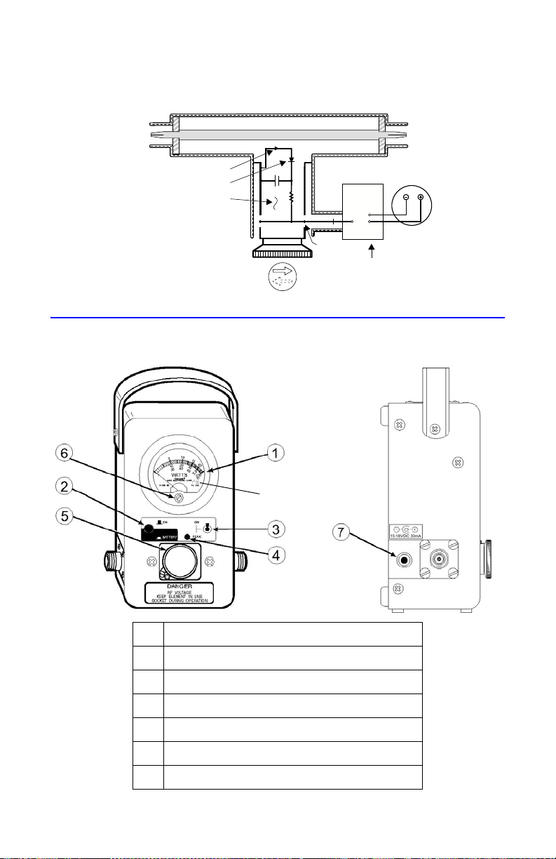
Figure 2 Schematic Diagram - Element
RF Coaxial Line
XMTR
or
LOAD
LOAD
or
XMTR
Directional Coupling
Diode
Detector Element
Meter
DC Contact
Circuit Board
Bat Line
Component Description
Figure 3 Component Diagram
1Meter
2 Battery Test Push Button
3 CW/PEAK Toggle Switch
4 PEAK Circuit Active Light
5 Element
6 Zero-Adjust Screw
7 DC Input Jack
7
Page 20

8
Page 21

Chapter 4 Operating Instructions
Zero Adjust Meter
Before taking any readings with the wattmeter, it is necessary to zero the meter
pointer under no-power conditions.
WARNING
Exposure to RF power radiation and the possibility of RF shock or burns exist
with some operating conditions. Always be sure to turn off the transmitter
when connecting or disconnecting a wattmeter.
Be sure the transmission line is terminated into a load or antenna.
When a Plug-In Element is removed from the RF line socket, the line section
center conductor is exposed. Do not put fingers or other objects into the
Plug-In Element socket while RF power is applied.
CAUTION
Use reasonable care in handling. Do not drop or subject the wattmeter or
elements to hard blows as accuracy may be impaired or other damage may
result.
CAUTION
Do not apply RF power to the wattmeter in excess of the full scale range of the
element.
1. Rotate Plug-In Element so that the arrow points down.
2. Set wattmeter’s control to CW mode.
3. Using a small screwdriver, turn the meter’s zero adjust screw (located in the
bottom center of the meter) clockwise or counterclockwise.
4. Ensure the meter pointer aligns with the zero mark on the meter scale.
9
Page 22

Plug-In Element Selection and Insertion
The elements determine the power range to be read on the meter scale. The
major markings (50 W, 100 W, etc.) are the full scale power value for that element. Elements are also marked for frequency range.
Note: The transmitter frequency must be within the band of the ele-
ment used.
• RF power measurements are made with the insertion of a Plug-In Ele-
ment. Insert the element into the line section’s socket.
• Forward power is indicated when the arrow on the element points in
the direction of power flow; from transmitter to load. Reflected power
measurements are made with the element rotated 180 and the arrow
pointing towards the transmitter.
Note: The element must be rotated fully when power measurements
are being made.
The index pin protruding from the element’s body should rest against the stop
on the line section in both the forward and reflected position. The small catch in
the lower left hand corner of the casting face should press down on the shoulder
of the Plug-In Element. This will keep the Plug-In Element in proper alignment
and ensure good contact with the dc pickup, the lower edge of the element and
the line section body.
Measurements
CW Power Measurements
1. Set the wattmeter control to CW mode.
2. Read the appropriate meter scale corresponding to the element full-scale value.
Example - A 2500 Watt element would use the 25 scale,
whereas a 5 Watt element would use the 50 scale.
Peak Power Measurements
1. Press the ON/BATTERY button to test the battery voltage level.
Note: If the pointer of the meter indicates below the battery test
zone, the batteries must be replaced. See “Replacing the Batteries” on
page 24.
Note: If the push button is pressed continuously for a length of time
exceeding 10 seconds, the battery test load will be disconnected from
the batteries. Do not read the battery level after this time because
once the load has been disconnected, the battery test reading will no
longer be accurate.
2. Set CW/PEAK switch to PEAK mode.
Note: The small indicating light to the left of “Peak” will be lit to
show Peak Mode Operation.
3. Read the appropriate meter scale corresponding to the element full-scale value.
10
Page 23

Load Power
W1WfWr–=
WfForwardPower=
WrReflectedPower=
Where an appreciable amount of power is reflected, as with an antenna, it is
necessary to subtract the reflected from the forward power to obtain the effective load power. Power delivered to and radiated by an antenna is given by:
Where: W
= load power
1
A load closely matched to 50 ohms resulting in a VSWR of 1.2 or less will require
less than a one percent correction. A good RF load resistor, such as a Bird Termaline Load Resistor, will produce this sort of negligible or unreadable reflected
power.
The Model 4314C Thruline Wattmeter used with a Bird Termaline Load Resistor
of proper power rating forms a highly useful absorption wattmeter. Since the
reflected power will be negligible, it will be unnecessary to rotate the element
from the forward direction.
Determining VSWR
The Model 4314C Thruline Wattmeter is not designed to provide direct VSWR
readings. In most cases, operators find that the ratio of forward to reflected
power is of equal use. However, VSWR readings can be determined very easily by
the use of the provided graphs as follows:
1. Determine the forward and reflected power as described above.
2. Using the appropriate VSWR Conversion Nomograph, determine the intersection of the forward and reflected power values.
Note: The slanted line passing closest to this point indicates the
VSWR.
11
Page 24
Figure 4 VSWR Conversion Nomograph
10
15
20
0.5
1.0
1.5
2.0
2.5
3.0
4.0
5.0
25
30 40
50
100 150 200
300 400
5
.2
.4
.6
.8
1.0
1.2
1.4
1.6
1.8
2.0
4
6
8
10
12
14
16
18
20
VSWR=
1+
Reflected Power
Forward Power
Reflected Power
Forward Power
1
FORWARD P
O
WER-WATT
S
REFLECTED POWER - WATTS
3.0
2.5
2.0
1.6
1.5
1.4
1.3
1.25
1.20
1.16
1.14
1.12
1.10
1.09
1.08
1.07
1.06
1.05
1.8
10
4.0
VSWR
12
Page 25

Figure 5 VSWR Conversion Nomograph
10
15
20
0.5
1.0
1.5
2.0
2.5
3.0
4.0
5.0
25
30 40
50
100 150 200
300 400
500
.01
.02
.03
.04
.05
.06
.07
.08
.09
.1
.2
.3
.4
.5
.6
.7
.8
.9
1.0
3.0
2.5
2.0
1.6
1.5
1.4
1.3
1.25
1.20
1.16
1.14
1.12
1.10
1.09
1.08
1.07
1.06
1.05
1.04
1.03
1.8
FORWARD P
O
WER-WATT
S
REFLECTED POWER - WATTS
10
4.0
VSWR
13
Page 26

Making Low Reflection Readings
It is sometimes desirable to make more accurate low reflection readings. This
can be done using a more sensitive element, provided that care is taken to prevent application of high forward power to the low-power element. This procedure is limited to use with higher power transmitters only.
1. Measure watts forward, using the proper Plug-In Element.
2. Reverse the arrow direction of the element to determine the general level of
reflected power.
3. Remove the Plug-In Element.
4. Insert a lower power element which has a maximum rating of more than
the reflected power indicated in the first measurement.
5. Insert the element, carefully, so that it reads reflected power only.
CAUTION
When making low reflection readings using a more sensitive element, take care
to insert the element so that it senses reflected power only. Do not rotate the
element in the socket so that it is subjected to forward power. This can result in
damage to the Plug-In Element, the wattmeter, or both.
6. Read the reflected power on the meter in the usual manner.
Note: When using the two-element method of reading low
reflected power, it is not recommended to use a pair of elements
which has a full scale power differential of greater than 10 to 1.
Testing Lines, Connectors, Filters & Related Components
Lines, connectors, filters, and related components can be tested using the Thruline Wattmeter. The method of testing depends upon the circumstances involved
for any particular test. Some of these tests are listed below:
The standing wave ratio or the reflected-power to forward-power ratio of a line
can be determined by terminating the line with a good load resistor, such as a
Bird Termaline Load Resistor. Proceed as described under determining VSWR.
Low reflected power may be measured as described above.
Line attenuation (power lost as heat in the line) can be determined by inserting
the line of unknown value between two Thruline Wattmeters. The end of the line
must be terminated by a load resistor. The attenuation of the line can be determined by comparing readings made at the two ends. Allowances must be made
for normal instrument error where very small values of attenuation are involved.
Some correction may be made by direct rigid connection of the Thruline Wattmeters.
14
Page 27

Determining Attenuation with a Single Wattmeter
dB 10
P
rfl
P
fwd
---------- -
log=
Note: This measurement must be supplemented with a reflected
power to forward power ratio check while using a load or with a DC
continuity check or leakage check, since open circuits or shorts may
exist part of the way along the line. The ratio determined in these tests
should be viewed as a rough estimate, since 100% of the power at the
open connector will not be reflected back.
Open Circuit Method
1. Attach an RF generator to the wattmeter’s input port.
2. Attach the section of transmission line that is to be measured to the output
port.
Note: The line section should be left open-ended.
3. Apply power.
4. Measure the Forward Power (P
fwd
).
5. Measure the Reflected Power.
6. Divide the Reflected Power reading in half to determine the Reflected
Power in the transmission line (P
).
rfl
Note: Because the power drop is being measured twice (down and
back).
7. Convert the reading to decibels by using this equation:
Short Circuit Method
Perform the Open Circuit Method with the exception of using a Short standard
on the end of the line being measured.
Note: The open circuit method is preferred because the ratio
(reflected power to forward power) is easier to achieve in an open circuit.
15
Page 28

Measuring Percentage Of Positive Modulation
PercentagePosMod
E
MAXECARRIER
–
E
CARRIER
-------------------------------------------- -x100=
PercentagePosMod
P
P
PC–
P
C
--------------------------- -
x100=
PercentagePosMod
P
P
P
C
---------- -
P
C
P
C
---------- -–
x100=
PercentagePosMod
P
P
P
C
---------- -1–
x100=
To measure the percentage of positive modulation in an amplitude modulation
system, employ the average and peak reading characteristics of the unit since:
By substitution we get:
Where: P
P = peak power as read with CW/PEAK switch in PEAK mode.
PC = carrier power as read with CW/PEAK switch in CW mode
Or:
And by cancellation:
After determining average and peak readings, find the intersection of the carrier
and peak powers on Figure 6 on page 17 to determine the percentage of positive modulation.
16
Page 29
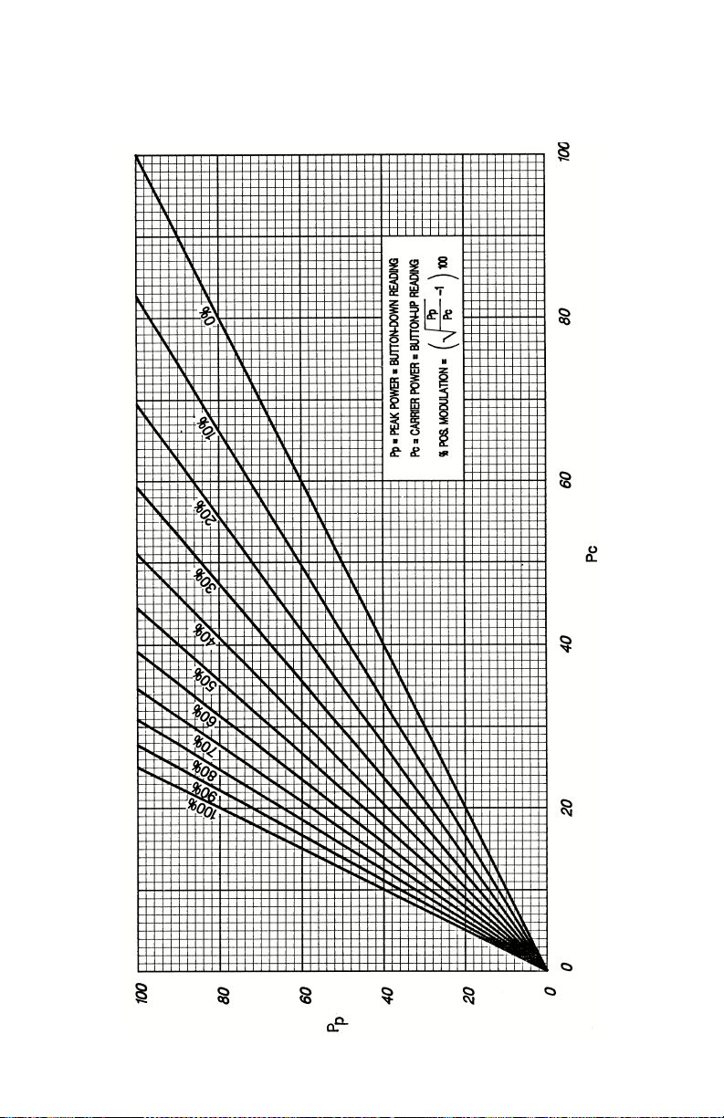
Figure 6 Graph Converting Carrier Power and Peak Power to Percent
17
Page 30

Performance Notes
Although the Model 4314C Thruline Wattmeter is equipped with Quick-Change
connectors, it must be remembered that the power rating and insertion loss
may be affected if other than “N” type connectors are used. Power limits must
be governed by the type of connector or transmission line used. For other types
of Quick-Change connectors, see Chapter 5 for the replacement parts list.
When a Model 4314C is used to match a load to a transmitter and a good match
is obtained, removing the instrument will not cause any change in the conditions. A well matched 50 ohm load can be placed at the end of a 50 ohm transmission line of any length without altering conditions at the transmitter.
When the load is not well matched, like an antenna with a VSWR of 1.5 or 2.0,
line length becomes critical since the length of line between a mismatched load
and the source transforms the impedance of the load as seen at the source. If
the adjustments for maximum power transfer were made with the Model 4314C
in place, removing it shortens the line by four inches plus two connectors. This
still is no cause for concern at low frequencies where four to five inches is a
small fraction of a wavelength. At higher frequencies; e.g., above 100 MHz, the
power output and frequency of the source may be affected.
To ensure that the impedance is identical on either side of ½ wavelength in the
transmission line with the Model 4314C either in or out of the line, it is only necessary to insert or remove a ½ wavelength.
Make up a length of cable which, when added to the Thruline Wattmeter, equals ½
wavelength at the frequency of measurement. If more than one frequency is
involved, then a separate cable is needed for each frequency. Use Figure 7 on
page 19 to determine the cable length required.
Note: When using UHF Plug PL-259, the cable length is measured
from tip to tip of center pin of plugs.
Note: When using other connectors, the cable length is measured
from the ends of the outer conductor
of the connectors.
18
Page 31
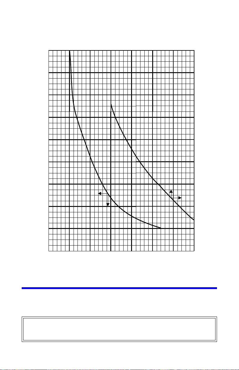
Figure 7 Cable Wavelength Matching Graph
200 300 400 600
0
4
8
12
16
20
28
24
32
36
700100
FREQUENCY (MEGAHERTZ)
500
C
A
B
L
E
L
E
N
G
T
H
I
N
C
H
E
S
I
N
C
H
E
S
(10)
(9)
(8)
(7)
(6)
(5)
(4)
MEGAHERTZ (600) (700) (800) (900) (1000)
Shutdown
1. Ensure the CW/PEAK switch is in CW mode.
Note: Leaving the unit in PEAK mode will shorten battery life.
WARNING
Always be sure transmitter power is off before disconnecting the unit from the
transmission line.
19
Page 32

20
Page 33

Chapter 5 Maintenance
Cleaning
If any of the contacts or line connectors become dirty, they should be cleaned
with a good contact cleaner or dry cleaning solvent on a cotton swab stick.
It is important to keep the following surfaces clean:
• Socket bore
• Element body circumference
• Bottom rim of the socket in the line section
• DC contacts on the element
Take care not to disturb the spring finger of the DC contact when cleaning the
socket bore. The spring finger can be manually adjusted. The button must be
pushed out far enough to make good contact with the element body but it must
not restrict the entry of the element.
Clean the meter and meter housing using a cloth moistened with a mild detergent solution. Do this only when necessary and take care not to allow water to
enter any of its circuitry as damage may result.
CAUTION
Use reasonable care in handling. Do not drop or subject the wattmeter or
elements to hard blows as accuracy may be impaired or other damage could
result.
Preventative Maintenance
Care and maintenance required for the 4314C Thruline Wattmeter is primarily
limited to cleaning. Keeping the Plug-In Element in the socket of the line section
as much as possible serves as an effective seal against the entry of dust and dirt
and to prevent damage to the meter. An aluminum dust plug may be used to
cover the socket opening when the element is removed.
Line Section Care
The RF connectors on the line section should also be protected against the entry
of dust and dirt by keeping them covered when the wattmeter is disconnected
from the RF line.
21
Page 34

If there is evidence of contamination inside the line section, the reachable portions should be cleaned and the interior carefully blown out.
Do not attempt to remove the RF center conductor under any circumstances.
Any attempt to do so will damage the assembly.
Inspection
Periodic inspections should be performed at six-month intervals.
• Inspect the meter for a cracked meter glass.
• Inspect wattmeter line section for a damaged or missing latch and pivot
pin assembly.
• Inspect all “QC” connectors for bent, broken, or missing pins.
Troubleshooting
Due to its complexity, field repair of the Model 4314C Thruline Wattmeter is recommended only for certain malfunctions. Only those functions within the scope
of normal maintenance are listed.
If a malfunction is not listed or not corrected by the listed corrective actions,
notify a qualified service center for further instructions.
PROBLEM
No meter
indication
(CW or PEAK)
22
POSSIBLE
CAUSE
No radio frequency Turn on transmitter .
Faulty RF section
assembly
Arrow on element
pointing in wrong
direction
Meter burned out or
damaged
No pick-up from DC
contact
Defective Plug-In
Element
Check transmitter operational conditions,
refer to operating instruction manual of
equipment used.
Check connections, interconnecting
cables, and auxiliary in-line equipment.
Rotate element so that arrow points in
direction of RF power flow.
Replace meter. See “Replacing the Meter”
on page 25.
Clean line section and element.See
“Cleaning” on page 21.
Check element. Replace element if
defective.
CORRECTION
Page 35

PROBLEM
No meter
indication
(PEAK only)
Erroneous or
inaccurate
Intermittent or
inconsistent
High VSWR or
high
percentage
reflected
power
POSSIBLE
CAUSE
Faulty instrumentation
module
Dead or low battery Test battery. See “Battery Procedures” on
Low battery Press ON/BATTERY selector switch to the
Shorted or opened
cable
Wattmeter out of
calibration
Faulty transmission
line, line connections,
antenna, or load
conditions
Dirty line section, DC
contact, and/or
element
Sticky meter Replace meter. See “Replacing the Meter”
Bad load or poor
load, antenna, or
connectors
Shorted or open
transmission line
Foreign material in
line section or in RF
connector bodies
Replace the instrumentation module, see
“Replacing the Instrumentation Module” on
page 26.
page 24. Replace if neccesary. See
“Replacing the Batteries” on page 24.
If pointer does not move from zero during
the battery test, remove the batteries and
measure their voltage. If less than 6.25
volts, replace the batteries. See “Replacing
the Batteries” on page 24.
BATTERY position. If the battery test
indicates weak batteries, replace them with
new ones. See “Replacing the Batteries”
on page 24.
Check connections, in-line equipment,
interconnecting cables, and auxiliary in-line
equipment.
Check calibration. See “Calibrating the
Wattmeter” on page 28.
Inspect and correct meter operation or
load.
Clean line section and element. See
“Cleaning” on page 21.
on page 25.
Replace connectors. See “Replacing the
Instrumentation Module” on page 26.
Replace transmission line.
Check for foreign material and clean as
required. See “Replacing the Meter” on
page 25.
CORRECTION
23
Page 36

Battery Procedures
Testing the Batteries
The Model 4314C Thruline Wattmeter uses two 9 V alkaline batteries to supply
power for the peak circuitry.
1. Press the ON/BATTERY switch.
Note: The meter pointer should travel to the right of the “BAT.TEST”
mark.
2. If the pointer stops below the mark, replace the batteries.
Note: If the push button is pressed continuously for a length of time
exceeding 10 seconds, the battery test load will be disconnected from
the batteries. Do not read the battery level after this time because
once the load has been disconnected, the battery test reading will no
longer be accurate.
Replacing the Batteries
1. Remove the back cover by unscrewing the four 8-32 Phillips flat head
screws.
Note: The screws are located two on each side of the meter housing
near the back edge at the top and bottom of the sides.
2. Pull the cover straight off.
3. Rotate the battery in its clip, then pull upward freeing the battery.
4. Remove the snap-on battery connector.
5. Insert the battery into the clip and replace.
6. Repeat above procedure for the other battery.
Figure 8 Replacing the Batteries
24
Page 37

Replacing the Meter
1. Remove the back cover by unscrewing the four 8-32 Phillips flat head
screws.
Note: The screws are located two on each side of the meter hous-
ing near the back edge at the top and bottom of the sides.
2. Loosen the two 8-32 nuts securing the meter leads.
3. Remove the meter leads.
4. Remove the two 10-32 oval head Phillips screws securing the meter shock
ring.
5. Pull the meter and shock ring assembly out of the housing from the back.
Note: If the three rubber shock mount buttons, P/N 4420-098, that
the meter rests on are to be reused, be careful not to lose them. However, if the replacement shock ring, P/N 4410A261, is to be used
instead, the buttons may be discarded.
6. Remove the meter retaining ring and shock mount from the meter.
7. Replace the meter.
Note: If the replacement shock ring is used, peel off the white strip
covering the adhesive backing. Carefully adhere the shock ring to the
front bezel flange.
Note: Be sure to observe the polarity when replacing the leads to the
meter, black to negative, orange to positive.
8. Zero adjust the meter by turning the adjustment screw found on the front
bottom center of the meter face.
Figure 9 Replacing the Meter
25
Page 38

Replacing the Instrumentation Module
CAUTION
This instrument contains static sensitive electronic components. Before
opening or servicing the unit, make sure that you understand and practice
electrostatic discharge component handling. Failure to comply may result in
permanent damage to sensitive components.
1. Remove the back as above in meter replacement.
Note: The instrumentation module contains the line section and cir-
cuit board chassis as an integral part.
2. Loosen the dress nut on the CW/PEAK switch.
Note: Care should be taken not to scratch the label.
3. Remove the wire assemblies from the batteries, meter, and DC jack.
4. Remove the battery wires (item 7) first at the printed circuit board by pulling up on the connector.
5. Remove the DC jack wires (item 5).
6. Remove the meter wires (item 3) also at the printed circuit board.
Note: Care should be taken not to break the wires.
Note: Note the wire location for ease of reassembly.
7. Remove the two oval head Phillips screws located on the front face of the
unit on either side of the line section element socket.
8. Pull the instrumentation module straight out from the back of the unit.
9. Replace the instrumentation module by reversing steps 1 - 8.
10. Zero Adjust the wattmeter. See “PEAK Mode Zero Adjust” on page 28.
CAUTION
If other than Female N type connectors are used, limit power and frequency to
the capabilities of the RF coaxial cable or connectors used. Damage to
connectors or errors in reading could result.
26
Page 39

Figure 10 Replacing the Instrumentation Module
2
1
3
7
5
4
6
8
1 Dressnut
2 Mounting Screws
3 Meter Wire Assembly (hidden from view)
4 Instrumenation Module
5 DC Jack Assembly
6 Housing Cover Assembly
7 Battery Cable Assembly
8 Housing Assembly
Replacing the Quick-Change Connectors
1. Remove the four 8-32 screws from each corner of the square flange on the
connector.
2. Pull the connector straight outward.
3. Install the new connector by reversing this procedure.
27
Page 40

Calibrating the Wattmeter
The 4314C requires a total of three calibrations to set zero and gain. These calibrations must be performed after the meter or instrumentation module has
been replaced. Additionally, a mechanical zero adjustment of the meter pointer
is done any time the pointer is not exactly aligned with the zero mark on the
meter scale when no power is being applied in CW mode.
Note: Before beginning this procedure, a DC Input element (4381-
050) is needed.
PEAK Mode Zero Adjust
To ensure that the meter reads correctly for both CW and PEAK operation:
1. Short the input by doing one of the following:
• Insert a dust plug
• Position a standard element with the arrow pointing down
2. Set the CW/PEAK switch to CW mode.
3. Ensure the pointer rests at 0.
Note: If the pointer needs to be adjusted, zero the pointer by turning
the mechanical zero adjustment screw located at the bottom front
center of the meter face. See “Zero Adjust Meter” on page 9
4. Set the CW/PEAK switch to PEAK mode.
5. Attach a voltmeter to the posts on the back of the meter.
6. Set the voltmeter to read in mV scale.
7. Slowly adjust the “ZERO ADJ.” potentiometer with a small screwdriver
(Figure 11 on page 29) until the reading shown on the voltmeter is 0.0mV.
8. Ensure that the pointer rests at 0.
Note: There should be no pointer position variation between CW and
PEAK modes.
PEAK Mode Gain Adjust
1. Remove the dust plug standard element, if present.
2. Insert DC Input element (4381-050) into the line socket.
3. Apply approximately 34 mV from a DC power supply to the connector on
the DC Input element.
Note: If a non-adjustable voltage supply is being used, install a volt-
age dividing potentiometer in series.
4. If necessary, adjust the “GAIN ADJ.” potentiometer with a small screwdriver
(Figure 11 on page 29) so that the same reading is attained in both CW and
PEAK modes.
28
Page 41

Note: This can be verified on both the voltmeter display and the
Zero Adjust
Potentiometer
Gain Adjust
Potentiometer
Meter
Posts
DC Element
DC Connector
meter face.
Note: Set the CW/PEAK switch to PEAK mode while watching the
meter pointer. The pointer should deviate or travel about 4/5 scale.
There should be no deviation of the pointer from CW to PEAK reading.
Figure 11 Calibration Potentiometer
Figure 12 DC Element Input
29
Page 42

Customer Service
Any maintenance or service procedure beyond the scope of those in this chapter
should be referred to a qualified service center.
If you need to return the unit for any reason, request an RMA through the Bird
Technologies website (link shown below). All instruments returned must be
shipped prepaid and to the attention of the RMA number.
Bird Service Center
30303 Aurora Road
Cleveland (Solon), Ohio 44139-2794
Fax: (440) 248-5426
E-mail: bsc@bird-technologies.com
For the location of the Sales Office nearest you, visit our website at:
http://www.bird-technologies.com
30
Page 43

Specifications
Impedance 50 ohms nominal
\
Insertion VSWR
With “N” Connectors 1.05 Max. to 1000 MHz, 1.1 Max. to 2300
MHz
Connectors Bird Quick Change “QC” Female N
normally supplied‘
RF Power Ranges
Average (CW) Mode
100 mW to 10 kilowatts (± 5% of full scale)
Peak-pulse or envelope-power
(PEAK) Mode
100 mW to 10 kilowatts (± 8% of full scale)
Frequency Range 0.45 to 2700 MHz (either mode)
Pulse Parameters
Minimum duty factor
Minimum repetition rate
Minimum pulse width
1.0 x 10⁻⁴
30 pps
0.4 microseconds at 100-2300 MHz
1.5 microseconds at 26-99 MHz
15 microseconds at 2-25 MHz
Weight (Approx.) 4 lb. (1.8 kg) with N-Connectors
Dimensions 3-5/8”L x 4”W x 7”H
(92.1 x 102 x 178 mm)
AC Power Requirements
(using adapter)
*
100-240 +/- 10% VAC @ 50/60Hz
Batteries Two 9 V alkaline
Battery Life 20 hours of operation, typically
*. Use only adapter supplied by Bird Technologies Group.
31
Page 44

Replacement Parts
Note: For this table, refer to Figure 13 on page 33.
Item Quantity Description Part Number
1 1 Housing assembly 4314-103
2 1 Instrumentation module 4314A202
3 1 Meter 2080-044
4 1 Battery cable assembly 4314A116
5 1 DC jack wire assembly 4314A117
6 1 Meter wire assembly 4314-119
7 2 9 V battery 5-1375
8 2 “QC” connectors (Female N normally
supplied)*
9 1 Housing cover assembly 4314A114
10 1 Dress nut (not shown) 5-1670
1 1 1 AC to DC converter (not shown) 5B2229-156E
*Available QC Type Connectors
Connector Part Number
N-Female 4240-062
N-Male 4240-063
HN-Female 4240-268
HN-Male 4240-278
LC-Female 4240-031
LC-Male 4240-025
BNC-Female 4240-125
BNC-Male 4240-132
L T-Female 4240-018
L T-Male 4240-012
C-Female 4240-100
C-Male 4240-110
UHF-Female (SO-239) 4240-050
UHF-Male (PL-259) 4240-179
7/8" EIA Air Line 4240-002
32
Page 45
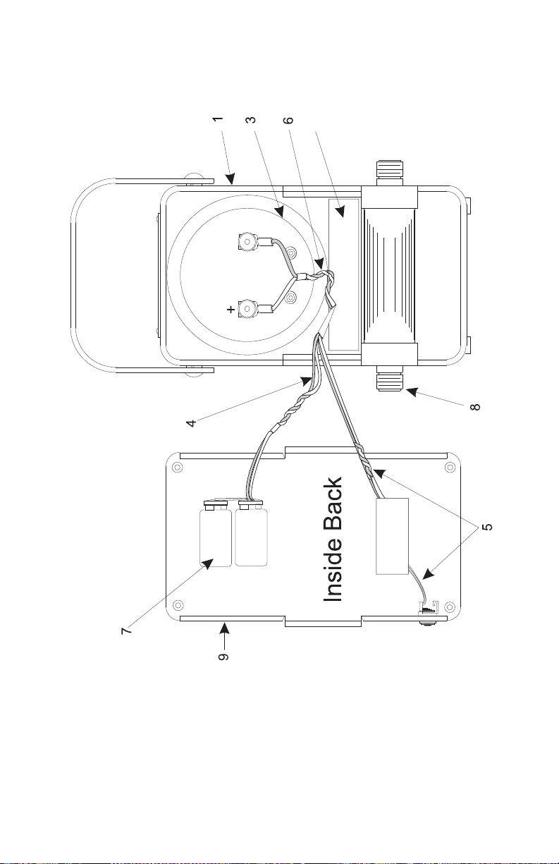
Figure 13 Replacement Parts
2
33
Page 46

34
Page 47

Limited Warranty
All products manufactured by Seller are warranted to be free from defects in
material and workmanship for a period of one year, unless otherwise specified,
from date of shipment and to conform to applicable specifications, drawings,
blueprints and/or samples. Seller’s sole obligation under these warranties shall
be to issue credit, repair or replace any item or part thereof which is proved to
be other than as warranted; no allowance shall be made for any labor charges of
Buyer for replacement of parts, adjustment or repairs, or any other work, unless
such charges are authorized in advance by Seller.
If Seller’s products are claimed to be defective in material or workmanship or
not to conform to specifications, drawings, blueprints and/or samples, Seller
shall, upon prompt notice thereof, either examine the products where they are
located or issue shipping instructions for return to Seller (transportation-charges
prepaid by Buyer). In the event any of our products are proved to be other than
as warranted, transportation costs (cheapest way) to and from Seller’s plant, will
be borne by Seller and reimbursement or credit will be made for amounts so
expended by Buyer. Every such claim for breach of these warranties shall be
deemed to be waived by Buyer unless made in writing within ten days from the
date of discovery of the defect.
The above warranties shall not extend to any products or parts thereof which
have been subjected to any misuse or neglect, damaged by accident, rendered
defective by reason of improper installation or by the performance of repairs or
alterations outside of our plant, and shall not apply to any goods or parts
thereof furnished by Buyer or acquired from others at Buyer’s request and/or to
Buyer’s specifications. Routine (regularly required) calibration is not covered
under this limited warranty. In addition, Seller’s warranties do not extend to the
failure of tubes, transistors, fuses and batteries, or to other equipment and parts
manufactured by others except to the extent of the original manufacturer’s warranty to Seller.
The obligations under the foregoing warranties are limited to the precise terms
thereof. These warranties provide exclusive remedies, expressly in lieu of all other
remedies including claims for special or consequential damages. SELLER NEITHER
MAKES NOR ASSUMES ANY OTHER WARRANTY WHATSOEVER, WHETHER EXPRESS,
STATUTORY, OR IMPLIED, INCLUDING WARRANTIES OF MERCHANTABILITY AND FITNESS, AND NO PERSON IS AUTHORIZED TO ASSUME FOR SELLER ANY OBLIGATION
OR LIABILITY NOT STRICTLY IN ACCORDANCE WITH THE FOREGOING.
35
Page 48

36
 Loading...