

Page 1
YOU'RE HEARD, LOUD AND CLEAR.
Installation and Operation Manual for
Compact Tower-Top Amplifier System
Models 429-83H-01-M/T
and 429-83H-01-M-48
Manual Part Number
7-9439
8625 Industrial Parkway, Angola, NY 14006 Tel: 716-549-4700 Fax: 716-549-4772 sales@birdrf.com www.bird-technologies.com
Page 2

Warranty
This warranty applies for one year from shipping date.
TX RX Systems Inc. warrants its products to be free from defect in material and workmanship at the time of shipment.
Our obligation under warranty is limited to replacement or repair, at our option, of any such products that shall have
been defective at the time of manufacture. TX RX Systems Inc. reserves the right to replace with merchandise of
equal performance although not identical in every way to that originally sold. TX RX Systems Inc. is not liable for dam-
age caused by lightning or other natural disasters. No product will be accepted for repair or replacement without our
prior written approval. The purchaser must prepay all shipping charges on returned products. TX RX Systems Inc.
shall in no event be liable for consequential damages, installation costs or expense of any nature resulting from the
purchase or use of products, whether or not they are used in accordance with instructions. This warranty is in lieu of all
other warranties, either expressed or implied, including any implied warranty or merchantability of fitness. No representative is authorized to assume for TX RX Systems Inc. any other liability or warranty than set forth above in connection with our products or services.
TERMS AND CONDITIONS OF SALE
PRICES AND TERMS:
Prices are FOB seller’s plant in Angola, NY domestic packaging only, and are subject to change without notice. Federal, State and local sales or excise taxes are not included in prices. When Net 30 terms are applicable, payment is
due within 30 days of invoice date. All orders are subject to a $100.00 net minimum.
QUOTATIONS:
Only written quotations are valid.
ACCEPTANCE OF ORDERS:
Acceptance of orders is valid only when so acknowledged in writing by the seller.
SHIPPING:
Unless otherwise agreed at the time the order is placed, seller reserves the right to make partial shipments for which
payment shall be made in accordance with seller’s stated terms. Shipments are made with transportation charges collect unless otherwise specified by the buyer. Seller’s best judgement will be used in routing, except that buyer’s routing
is used where practicable. The seller is not responsible for selection of most economical or timeliest routing.
CLAIMS:
All claims for damage or loss in transit must be made promptly by the buyer against the carrier. All claims for shortages
must be made within 30 days after date of shipment of material from the seller’s plant.
SPECIFICATION CHANGES OR MODIFICATIONS:
All designs and specifications of seller’s products are subject to change without notice provided the changes or modifications do not affect performance.
RETURN MATERIAL:
Product or material may be returned for credit only after written authorization from the seller, as to which seller shall
have sole discretion. In the event of such authorization, credit given shall not exceed 80 percent of the original purchase. In no case will Seller authorize return of material more than 90 days after shipment from Seller’s plant. Credit
for returned material is issued by the Seller only to the original purchaser.
ORDER CANCELLATION OR ALTERATION:
Cancellation or alteration of acknowledged orders by the buyer will be accepted only on terms that protect the seller
against loss.
NON WARRANTY REPAIRS AND RETURN WORK:
Consult seller’s plant for pricing. Buyer must prepay all transportation charges to seller’s plant. Standard shipping policy set forth above shall apply with respect to return shipment from TX RX Systems Inc. to buyer.
DISCLAIMER
Product part numbering in photographs and drawings is accurate at time of printing. Part number labels on TX RX
products supersede part numbers given within this manual. Information is subject to change without notice.
Bird Technologies Group TX RX Systems Inc.
Page 3
Symbols Commonly Used
WARNING
ESD Electrostatic Discharge
Hot Surface
Electrical Shock Hazard
Important Information
CAUTION or ATTENTION
High Voltage
Heavy Lifting
Bird Technologies Group TX RX Systems Inc.
NOTE
Manual Part Number 7-9439
Copyright © 2009 TX RX Systems, Inc.
First Printing: June 2007
Version Number Version Date
1 06/08/07
2 08/17/07
3 10/10/07
4 02/08/08
5 10/24/08
6 09/03/09
Page 4

Changes to this Manual
We have made every effort to ensure this manual is accurate. If you discover any
errors, or if you have suggestions for improving this manual, please send your
comments to our Angola, New York facility to the attention of the Technical Publications
Department. This manual may be periodically updated. When inquiring about updates to
this manual refer to the manual part number and revision number on the revision page
following the front cover.
Contact Information
Sales Support at 716-217-3113
Customer Service at 716-217-3144
Technical Publications at 716-549-4700 extension 5019
Bird Technologies Group TX RX Systems Inc.
Page 5

Table of Contents
General Description ............................................................................................ 1
Unpacking ............................................................................................................ 4
Pre-Installation Checkout ................................................................................... 4
Mechanical Inspection ....................................................................................... 4
Initial Power-up Test ........................................................................................... 5
Bench Testing ..................................................................................................... 6
Installation............................................................................................................ 8
Base to Tower-Top Communications ................................................................. 8
Test Transmission Line ...................................................................................... 9
Installing the System .......................................................................................... 9
Installing the Tower-Top Box ............................................................................. 9
In-building Lightning Arresters ............................................................................ 9
Installing the MCU ............................................................................................12
Interference and IM Considerations.................................................................. 14
Feedline Data ..................................................................................................... 14
Optimizing The System ..................................................................................... 15
Attenuation Settings ......................................................................................... 15
TTA Net Gain.....................................................................................................15
Receiver Multicoupler Distribution ..................................................................... 15
Setting the TTA NET GAIN Attenuation ............................................................ 16
Determining Needed Attenuation .................................................................... 16
Setting Distribution Attenuation ......................................................................... 17
Spectrum Analysis ............................................................................................ 17
Procedure for Spectral Analysis......................................................................19
Operational Tests (Sensitivity and Degradation) ........................................... 19
Front Panel Test Port ........................................................................................ 19
Tower Top Amplifier Inputs................................................................................ 19
Static System Sensitivity ................................................................................... 19
Measuring Static Sensitivity (Load Connected) ................................................. 19
Effective System Sensitivity............................................................................... 21
Measuring Effective Sensitivity (Antenna Connected)....................................... 22
Degradation ....................................................................................................... 23
Routine Operation ............................................................................................. 23
Amplifier Monitoring ........................................................................................... 23
LCD Display.......................................................................................................23
Current Draw ................................................................................................... 23
Test Cable Connection .................................................................................... 23
TTA Temperature ............................................................................................ 23
Software Version ............................................................................................. 23
Front Panel LEDs .............................................................................................. 24
Form-C Contacts ............................................................................................... 24
Alarms ................................................................................................................ 24
The Test Mode ................................................................................................... 24
Set LNA X Active ............................................................................................... 24
Terminate LNA X ............................................................................................... 25
Un-Terminate LNA X ......................................................................................... 25
System Troubleshooting .................................................................................. 25
Performance Degradation ................................................................................ 25
Hardware Problems .......................................................................................... 25
Lightning and Lightning Arresters ................................................................... 26
Vandalism ....................................................................................................... 26
AC Line Fuse (Model 429-83H-01-M) ...............................................................26
Table of Contents Manual 7-9439-6 09/03/09
Page 6

Disconnected Cables ........................................................................................ 26
Periodic Maintenance........................................................................................27
Recommended Spare Parts.............................................................................. 27
Optional Equipment .......................................................................................... 27
Narrowband Filter .............................................................................................. 27
Multicoupler Expansion Deck ............................................................................ 28
Figures and Tables
Figure 1: Front view of the tower-top box ............................................................ 1
Figure 2A: Top view of the multicoupler unit (MCU) ............................................ 2
Figure 2B: Front view of the MCU ....................................................................... 2
Figure 2C: Back view of the MCU ....................................................................... 2
Figure 3: Cable connections for system components .......................................... 4
Figure 4: Initial power-up test ............................................................................... 5
Figure 5: Boot-up sequence ................................................................................. 6
Figure 6: Default display ....................................................................................... 6
Figure 7: Menu selections .................................................................................... 7
Figure 8: Test equipment interconnection for “bench testing” ............................. 8
Figure 9A: System installation guidelines .......................................................... 10
Figure 9B: System installation guideline notes................................................... 11
Figure 10: Tower-top box mechanical details ...................................................... 9
Figure 11: Application of rubber splicing tape ................................................... 12
Figure 12: Lightning Arrester .............................................................................. 12
Figure 13: Optional Data Network Protector....................................................... 13
Figure 14: Alarm terminals ................................................................................ 14
Figure 15: Testing the output spectrum ............................................................. 18
Figure 16: Maximum signal level mask ............................................................. 18
Figure 17: Calculating actual sensitivity ............................................................. 20
Figure 18: Measuring sensitivity through the test port ....................................... 21
Figure 19: Optional filter interconnect diagram .................................................. 28
Figure 20: Optional multicoupler expansion deck .............................................. 28
Table 1: System Specifications ............................................................................. 1
Table 2: Tower Box Specifications......................................................................... 3
Table 3: Multicoupling Unit Specifications............................................................. 3
Table 4: Bench Test Results.................................................................................. 6
Table 5: Optimum Total TTA NET GAIN .............................................................. 16
Table 6: Distribution Attenuation Settings ........................................................... 17
Table 7: Amplifier Status Troubleshooting Guide ................................................ 22
Table 8: Typical Current Readings ...................................................................... 23
Table 9: Loss of Sensitivity Troubleshooting Guide ............................................ 26
Table 10: Disconnected Cables .......................................................................... 27
Table 11: Optional Narrowband Filters................................................................27
Table of Contents Manual 7-9439-6 09/03/09
Page 7

Appendixes
Appendix A: Front Panel Ethernet Connectivity ................................................. 29
Ethernet Connectivity .......................................................................................... 29
Direct Connection .............................................................................................. 29
Required Equipment ........................................................................................ 29
Procedure ........................................................................................................ 29
Networked Connection ...................................................................................... 30
Required Equipment ........................................................................................ 32
Procedure ........................................................................................................ 32
TTA Network Port Security ................................................................................ 34
Data Encryption ............................................................................................... 34
SNMP Support Disabled..................................................................................34
Telnet Security ................................................................................................. 34
Changing the Telnet Port Password................................................................... 35
Appendix B: Changing your Service Computer IP Address............................... 36
Table of Contents Manual 7-9439-6 09/03/09
Page 8

Table of Contents Manual 7-9439-6 09/03/09
Page 9
GENERAL DESCRIPTION
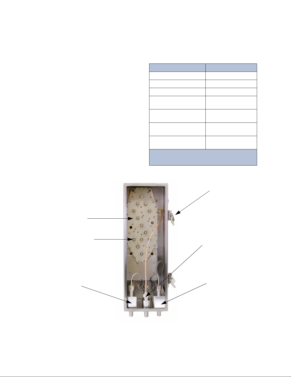
Figure 1: Front view of the tower-top box (door removed for clarity).
Amplifier / Filter
Assembly
3-21548
Surge
Suppressor
8-21514
Door
Clamp
Surge
Suppressor
8-21183
Surge
Suppressor
8-21549
Tuning Screw
DO NOT ADJUST
Parameter Specification
Bandwidth 792 - 824 MHz
Noise Figure 2.9 dB typ, 3.5 dB max
3rd order IIP > 15.0 dBm
TTA Net Gain Fully settable by
electronic attenuator
Rejection 110 dB Min, 120 db Nom
@776 and 851 MHz
AC Current
(model 429-83H-01-M) 340 mA (typ) @120 VAC
DC Current
(model 429-83H-01-M-48) 780 mA (typ) @ 48 VDC
Table 1: System specifications.
13 dB TTA Net Gain and
maximum 6 dB transmission line loss assumed
Your TXRX Systems Inc. Tower Top Amplifier System provides the highest degree of reliability available in a Tower Top Amplifier (TTA). The system
uses quadrature-coupled amplifiers (also called
balanced amplifiers) to create a redundant amplifier configuration in both the tower box and the
receiver multicoupling unit (MCU). Each quadamplifier provides two simultaneously used, essentially parallel paths of amplification. Failure of one
of these paths of amplification results in an overall
gain reduction of only 6 dB.
The system also supplies automatic backup-amplifier switching in the tower top box. Fault detection
circuitry continuously monitors the DC power operation of the primary quad-amplifier and automatically switches to the identical secondary quadamplifier if conditions indicate a primary malfunction. If the secondary quad-amplifier malfunctions,
operation switches to whichever quad-amplifier is
still providing some gain due to operation of one of
its amplification paths. Fault detection circuitry also
provides at-a-glance status reporting, with frontpanel LED ’s a nd an LCD displ ay. The sy stem
specifications for the tower top amplifier are listed
in Table 1.
TX RX Systems Inc. Manual 7-9439-6 09/03/09 Page 1
Page 10
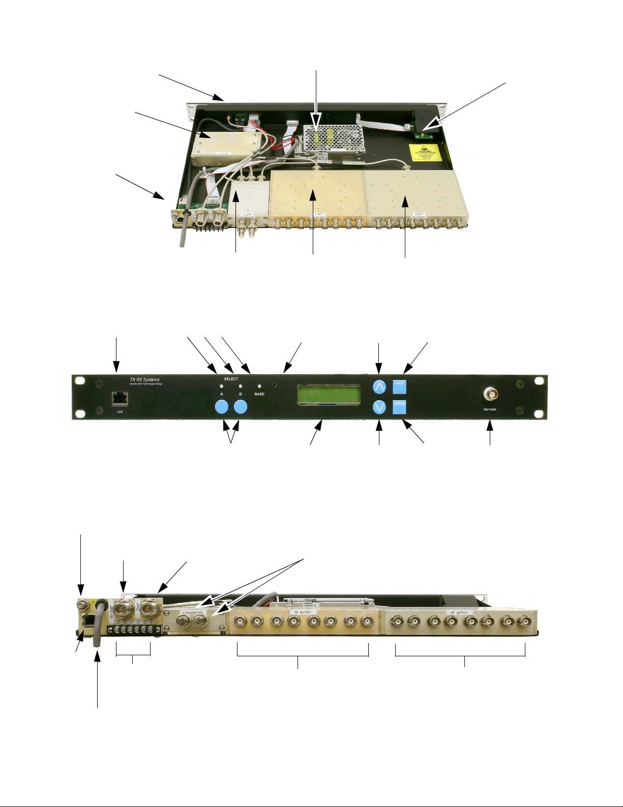
Figure 2C: Back view of the MCU. Model 429-83H-01-M shown.
Ground
Test
cable
Transmission
cable
To additional 8-way dividers
on optional expansion deck.
Terminate when unused.
CAT-5
Cable
here
AC or DC Cord
(model dependent)
Alarm
Terminals
To station receivers
Unused ports do not
require termination
To station receivers
Unused ports do not
require termination
Figure 2B: Front view of the MCU. Model 429-83H-01-M shown.
LAN Port
Status LED’s
Contrast
Adjust
Up
Button
Cancel
Button
Amplifier Select
Buttons
Down
Button
Enter
Button
Test
Port
Display
Figure 2A: Top view of the Multicoupling Unit (MCU). Model 429-83H-01-M shown.
8-21515 Power Supply
(model 429-83H-01-M
)
3-21516 DC-DC Converter
(model 429-83H-01-M-48)
3-21476
Front Ethernet Board
(under shroud)
3-21453
Front Panel Board
(under shroud)
3-21450
Distribution Amp
3-21496
Rear Panel
Board
3-18173
4-Way Divider
3-18171
8-Way Divider
3-18171
8-Way Divider
TX RX Systems Inc. Manual 7-9439-6 09/03/09 Page 2
Page 11

The quad-amplifier in the tower top box amplifies
Electrical Specifications
Frequency Range 792 to 824 MHz
Net Gain 23 dB
Noise Figure (typ /max) 2.7 / 3.0 dB
Backup Amplifier Switching Solid State RF Switch
Integrated Test Port
Isolation
45 dB
Preselector Type
Loss
Rejection
7-pole TEM Bandpass
with cross-couplings
<0.8 dB
>60 dB @ 776 and 851 MHz
LNA Type
Gain
Noise Figure
3rd Order Input IP
2-stage Quadrature
integrated into filter
26 dB
1.2 dB
18 dBm
Impedance 50 Ohms
Antenna Port VSWR 2 : 1
Power Requirements 12 VDC @ 1.25 A
Lightning Protection Impulse Suppressor on all
external connectors
Operating Temp Range -30° C to +60° C
Mechanical Specifications
Enclosure Modified NEMA 4x:
Stainless steel
weather resistant
Connectors N -female
Dimensions (HWD)
not including mounting tabs
and connectors
18” x 6” x 6”
(457 x 152 x 152 mm)
Net Weight 20 lbs (9.1 kg)
Table 2: Tower box specifications. Values are typical unless
noted otherwise.
Electrical Specifications
Frequency Range 792 to 824 MHz
Multicoupler Net Gain +1 dB typ; 0 dB min
Distribution Amp Type
Gain
Noise Figure
1 dB compression point
3rd Order Output IP
Quad-Coupled dual stage
23 dB
4 dB
27 dBm
46 dBm
Number of Outputs
Split Loss
16 or 32
18 dB
Impedance 50 Ohms
VSWR <2 : 1
Connectors
to TTA
to BTS
Test Port input
N - Female
BNC - Female
BNC - Female
TTA NET GAIN
electronic attenuator
0 to 15.5 dB
in 0.5 dB steps
DISTRIBUTION
electronic attenuator
0 to 3 db
in 0.5 dB steps
Alarm / Warning Contacts Two Form-C Contacts
Nominal 2A @ 30 VDC
or 0.5A @125 VAC
I/O Ethernet
Power Requirements
Model 429-83H-01-M
Model 429-83H-01-M-48
90 - 240 Vac @ 50/60 Hz
-48VDC
Operating Temp Range 0° C to + 50° C
Mechanical Specifications
Enclosure Standard EIA 19” Rack Mount
Dimensions (HWD) 1 RU x 19” x 14”
(38 x 483 x 356 mm)
Net Weight 10.5 lbs (4.8 kg)
Table 3: Multicoupling Unit specifications. Values are
typical unless noted otherwise.
the weak received signal before the signal enters a
long and lossy transmission line, thus preventing
the line loss from degrading the signal-to-noise
ratio. The quadrature amplifiers have a separate
power circuit for each half of the amplifier which
provides component redundancy as well as unsurpassed IM performance. Microprocessor controlled
fault detection circuitry in the tower top box provides continuous monitoring and switching of each
quad amplifier while sending operational data to
the base unit front panel for at-a-glance status
reporting and form-C contact switching for alarm
integration. Included in the tower top box is a pre-
TX RX Systems Inc. Manual 7-9439-6 09/03/09 Page 3
selector fil ter, amplifi er “A” and ampli fier “B,”
switching circuitry, control board and PolyPhaser
surge suppressors (see Figure 1). The specifications for the tower box are listed in Table 2.
The ground-mounted MCU shown in Figures 2A
through 2C is intended for 19-inch rack mounting.
It houses amplifier and signal distribution assemblies, alarm indicators, a power supply or DC-DC
Page 12
conver ter, and a display panel to provide visual
NOTE
Test
Port Trans
To
Station ReceiversToStation Receivers
To
120
VAC
CAT-5e Cable
Test
Port
Main
Transmission
Main
Main
Test
Antenna
MCU
Tower Top Box
Lightning Arrester
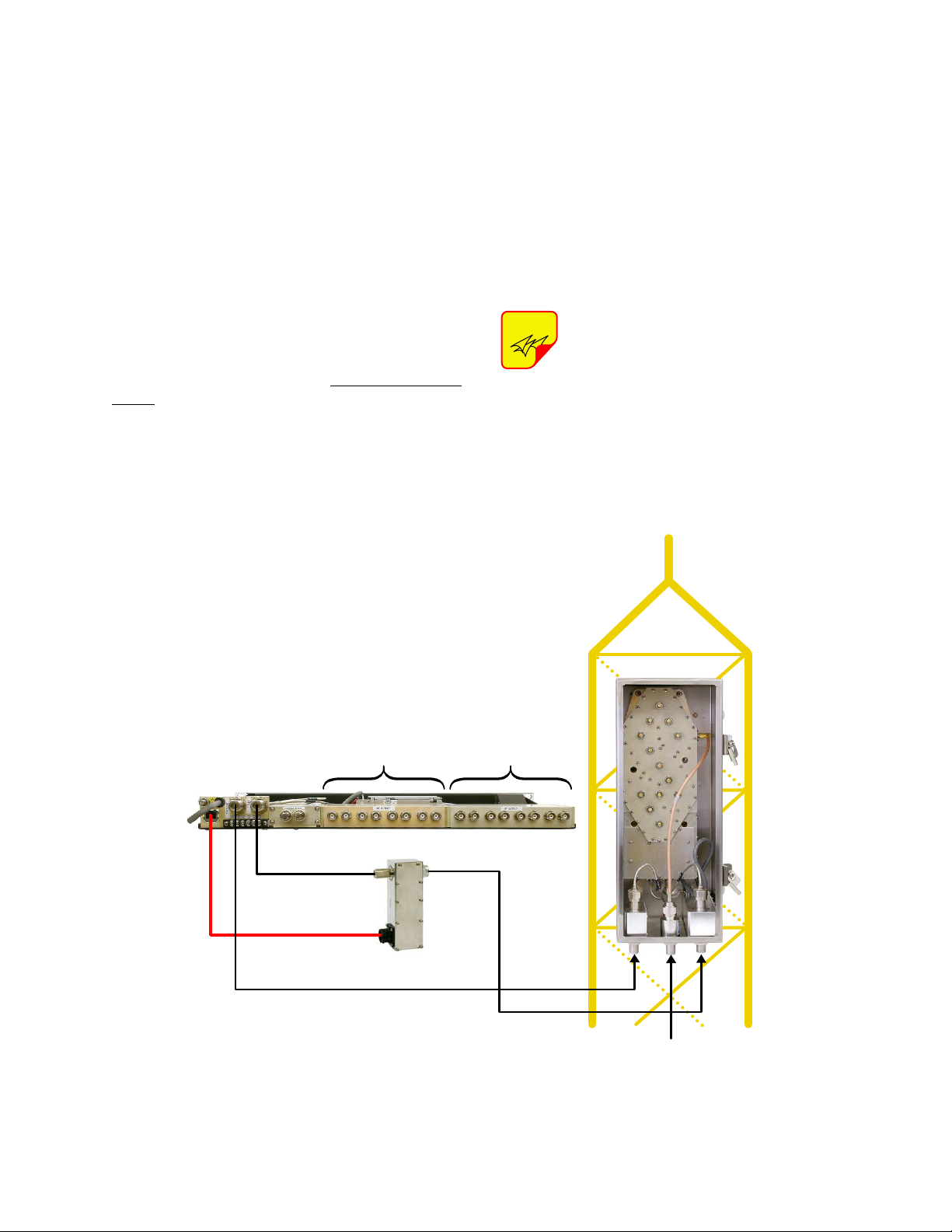
TX RX part no.8-21550
Figure 3: Cable connections for system components. Model 429-83H-01-M shown.
feedback on the system’s operating status. The
specifications for the MCU are listed in Table 3.
Also included in the system is a webpage user
interface for controlling and monitoring of amplifier
currents, alarms, and attenuators. The webpage
user interface is accessed through the front panel
LAN connector. Refer to Appendix A for instructions on accessing this feature.
PRE-INSTALLATION CHECKOUT
The following pre-installation tests should be performed after unpacking the system to verify nothing
has loosened during transit. Additionally, the system should be made operational on the bench with
all components at ground level to verify proper
electrical performance. Figure 3 illustrates all of
the cable connection points for both the tower top
box and the MCU.
UNPACKING
Each major component of the TTA system is individually packaged and shipped via motor freight or
UPS. It is important to report any visible damage to
the carrier immediately. It is the customer's responsibility to file damage claims with the carrier within
a short period of time after delivery (1 to 5 days).
The tower top box should NOT be
installed on the tower until all of the
pre-installation tests are successfully
completed.
Mechanical Inspection
Open the tower top box by loosening all the doorclamp locking screws and rotating the clamps to
TX RX Systems Inc. Manual 7-9439-6 09/03/09 Page 4
Page 13
release the door. Make sure that all of the connec-
Tower Top Box
MCU
Lightning Arrester
TX RX part no. 8-21550
CAT-5e
Cable
Front
Panel
Test
Port
Test Ant Main
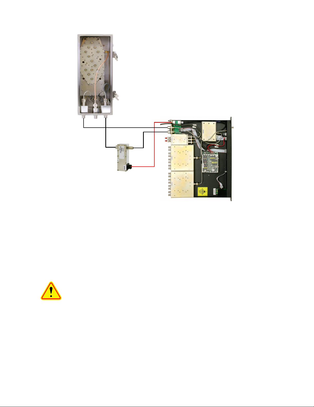
Figure 4: Initial power-up test.
tors are tight. In addition, it is advisable to check
the tightness of the hold-down screws for the various assemblies to insure nothing loosened during
shipment. Likewise, check all of the cable connections on the MCU to insure they are all properly
mated to their associated plugs.
Initial Power-Up Test
To perform the initial power-up test the system
should be temporarily interconnected at ground
level using short cables. Figure 4 shows the tem-
TX RX Systems Inc. Manual 7-9439-6 09/03/09 Page 5
CAUTION: The wide band filter in
the tower top box is factory tuned
and must not be field adjusted. Field
tuning of this filter is not required. Do
not adjust the tuning sl ugs o f the
amplifier/filter assembly.
porary equipment hookup for initial power-up testing.
Once the equipment is temporarily interconnected
then power is applied to the system by plugging the
MCU’s AC cord into a suitable AC outlet (model
429-83H-01-M) or connecting the DC power cable
to a suitable -48 VDC supply (model 429-83H-01M-48). The following start-up sequence occurs.
1) At turn-on, the three front panel status LED’s
will all glow a steady red while the display panel
shows a row of solid boxes on the top display
line. This will last for about 10 seconds while
the systems micro-controllers boot-up.
2) During the next 5 seconds the base unit (MCU)
will establish communications with the tower
box. The front panel status LED’s will occasionally flash green. The display panel will present
the message “Connecting to Tower Controller”
and then will briefly flash the MCU’s current
software version. See Figure 5.
Page 14
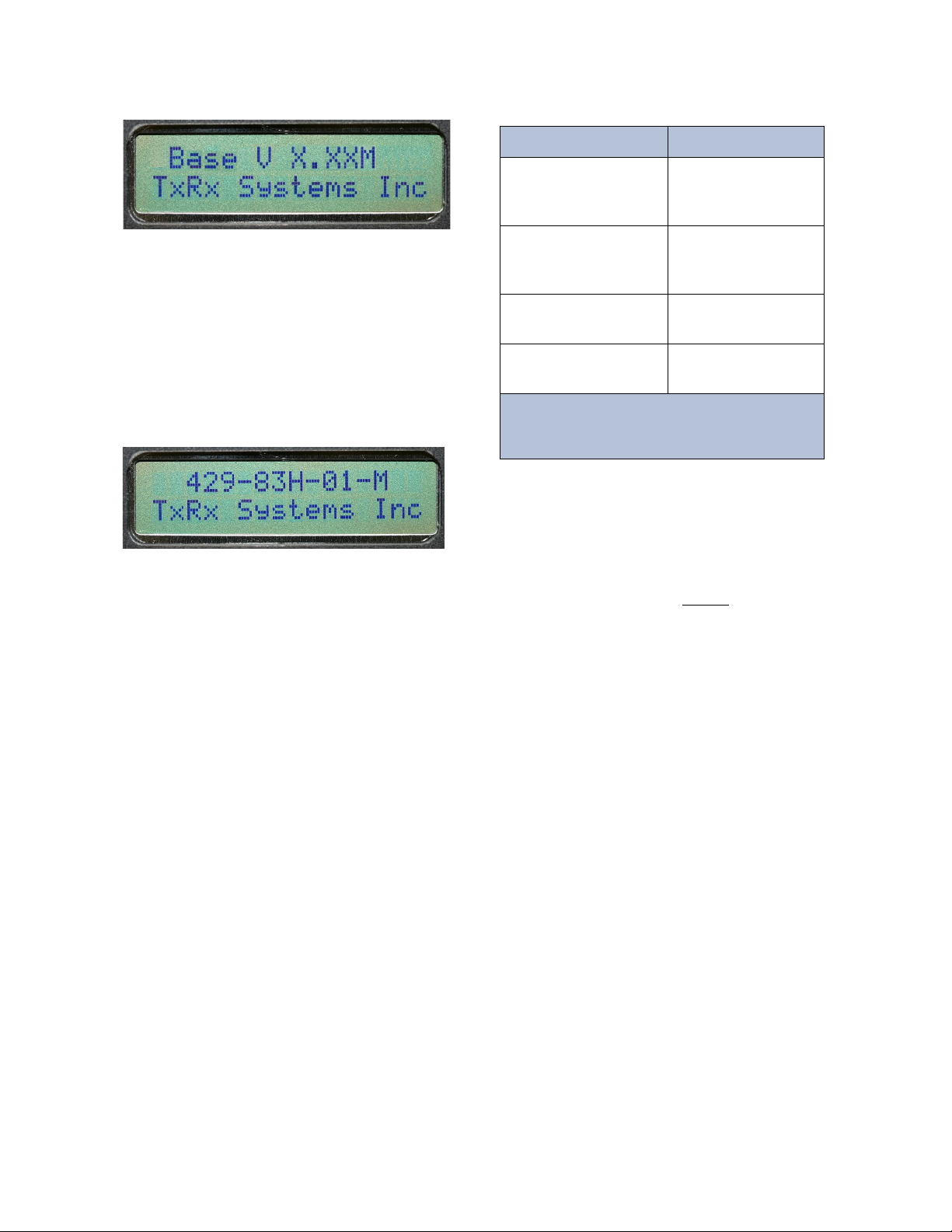
3) After the power-up sequencing is complete the
Test Performed Result
Stand Alone
Receiver
Sensitivity
dBm
* Bench Test
Static
Sensitivity dBm
Model Number
(Tower Top Box)
Serial Number
(Tower Top Box)
Table 4: Bench Test Results.
* Default “TTA NET GAIN“ Attenuation (3.0 dB)
* Default “DISTRIBUTION” Attenuation (1.0 dB)
Figure 6: Default display.
Figure 5: MCU software version is displayed briefly
during the boot-up sequence.
screen should show the default display as
shown in Figure 6. The status LED for each
active amplifier will glow a steady green and the
status LED for the inactive (stand-by) LNA will
be dark.
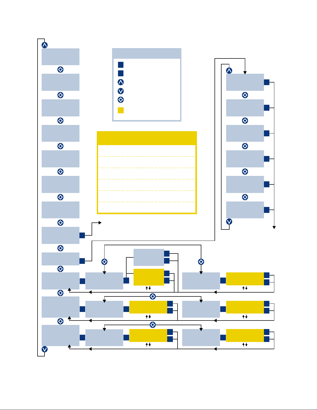
The tower top amplifier system is software directed
so control of the system is accomplished via user
interface with the front panel using the display
screen and the four menu selection buttons. A flow
chart showing all of the possible user menu selections is shown in Figure 7.
Bench Testing
The purpose of the bench test is to verify that all of
the system components are working correctly and
to measure the systems sensitivity before climbing
the tower to mount the tower top box. One station
receiver is selected and the test is performed at
this frequency. Short temporary cables are used to
interconnect all components. A SINAD meter is
used for the test (or a bit e r r o r rate m et e r if
required) along with a signal generator.
1) The stand-alone receiver sensitivity is measured and recorded first. Record the value in
Table 4.
2) Connect the equipment as shown in Figure 8.
Be sure that the signal generator is setup for a 3
KHz deviation with a 1000 Hz tone (analog) or
proper pattern for BER testing.
3) Measure and record the systems bench test
static sensitivity in table 4. The sensitivity value
will vary depending on the amount of internal
programmable attenuation selected via software interface. The bench test measurement
should be taken with the default values selected
for “TTA NET GAIN” attenuation (3.0 dB) and
“DISTRIBUTION” attenuation (1.0 dB). These
are the factory default settings that are programmed into your system when you first turn it
on.
4) Select the other tower top amplifier and check
that the bench test static sensitivity value
remains nearly the same. This will insure that
both amplifiers in the tower top box are functioning properly. To select an alternate towertop amplifier press the associated amplifier
select button on the front panel, the status LED
will begin to flash, then press the ENTER button
to finalize the selection.
5) If the tower box door is opened during the
installation it is important to re-tighten the doorclamp locking screws uniformly so that the door
gasket seal is maintained. Tighten each clamp
about half-way, then start back at the first clamp
and fully tighten each one in the same order.
Tighten with a hand tool only. Insure that the
moisture vent holes at the bottom of the box are
unobstructed.
TX RX Systems Inc. Manual 7-9439-6 09/03/09 Page 6
Page 15
TTA NET GAIN
DISTRIBUTION
MAIN LINE LOSS
TEST LINE LOSS
STATIC W/LOAD
REFERENCE W/ANT
AS AN EASY REFERENCE
RECORD VALUES HERE
NOTE: Use arrow to adjust
NOTE: Use arrow to adjust
NOTE: Use arrow to adjust
NOTE: Use arrow to adjust
NOTE: Use arrow to adjust
NOTE: Use arrow to adjust
429-83H-01-M
TX RX SYSTEMS INC
DEFAULT
DISPLAY
PRESS CANCEL KEY
LNA X ACTIVE
A CURRENT XXXmA
B CURRENT XXXmA
BASE CURRENT
XXXX mA
TEST CABLE
CONNECTED
NOT CONNECTED
TTA TEMPERATURE
+/- XX DEGREES C
BASE V X.XX
TOWER V X.XX
INITIALIZE
ENTER TO RESTART
TEST
ENTER TO SELECT
ATTENUATORS
ENTER TO SELECT
FEEDLINE DATA
ENTER TO SELECT
SENSITIVITY
ENTER TO SELECT
TTA NET GAIN
ENTER TO ADJUST
MAIN LINE LOSS
ENTER TO ADJUST
STATIC W/LOAD
ENTER TO ADJUST
Manual Mode
TTA NET GAIN
X.X dB
Automatic Mode
TTA NET GAIN
AUTO MODE
MAIN LINE LOSS
X.X dB
STATIC W/LOAD
-XX.X dB
DISTRIBUTION
ENTER TO ADJUST
TEST LINE LOSS
ENTER TO ADJUST
REFERENCE W/ANT
ENTER TO ADJUST
DISTRIBUTION
X.X dB
TEST LINE LOSS
XX.X dB
REFERENCE W/ANT
-XX.X dB
SET LNA A ACTIVE
ENTER TO CONFIRM
SET LNA B ACTIVE
ENTER TO CONFIRM
TERMINATE LNA A
ENTER TO CONFIRM
TERMINATE LNA B
ENTER TO CONFIRM
UNTERM LNA A
ENTER TO CONFIRM
UNTERM LNA B
ENTER TO CONFIRM
Return to
Default
Display
NOTE:
After pressing the ENTER Button the MCU
will re-boot, then return to the
Default Display.
PRESS ENTER KEY
PRESS UP-ARROW KEY
PRESS DOWN-ARROW KEY
PRESS EITHER ARROW KEY
YELLOW INDICATES
RECORDABLE VALUE
KEY
429-83H-01-M Menu System
C
E
E
E E
E E
E
E
E
E
C
E
C
E
C
C
C
C
C
C
C
E
C
E
C
E
E
E
E
C
E
C
Figure 7: 429-83H-01-M menu selections.
TX RX Systems Inc. Manual 7-9439-6 09/03/09 Page 7
Page 16

Minimum length cables
Best possible sensitivity
Default "TTA NET GAIN" Attenuation (3.0 dB)
Default Distribution Attenuation (1.0 dB)
Signal Generator
MCU
Front
Panel
Test
Port
Tower Top Box
Lightning Arrester
TX RX part no. 8-21550
12 dB SINAD Receiver
CAT-5e
Cable
Diagnostic Cable
Test Ant Main
Figure 8: Test equipment interconnection for “bench testing” of system components.
Connection to an appropriate power source is assumed.
The following sub-sections of the manual discuss
general considerations for installing the system. All
work should be performed by qualified personal.
TXRX Systems provides the base MCU, tower top
amplifier box, and the mainline lightning arrester.
All additional parts required for installation must be
supplied by the customer. Before mounting the
tower top box we recommend that you record the
model number and serial number of the unit for
future reference (table 4 is a convenient place to
record them). The numbers are located on a tag
attache d to the inside of t h e door and maybe
required in the future if you call the factory for customer support.
TX RX Systems Inc. Manual 7-9439-6 09/03/09 Page 8
INSTALLATION
Base to Tower-Top Communications
A special lightning arrester (TXRX part # 8-21550)
is provided with this TTA for installation at the main
transmission line entry bulkhead/grounding plate.
This unit not only passes the DC current required
to operate the TTA, but also generates the low frequency subcarrier used for the standard AISG/EIA485 data communications between the base unit
and the tower top box. A standard CAT-5e data
cable (double shielded) must be installed between
the base unit (MCU) and the lightning arrester for
carriage of the EIA-485 data. The TTA will operate
normally with all backup functionality intact if this
data cable is not installed, is damaged or removed,
but status and alarms will not be available at the
base.
Page 17

Test Transmission Line
NOTE
Mounting Tabs
.312 Dia Thru
Mount Holes
4 Places
6.69"
12.00"
Figure 10: Tower-top box mechanical details.
Prope r installati on of this system requires t he
installation of a test transmission line in addition to
the main transmission line for system testing and
diagnostics. The system will operate normally if the
test transmission line is not installed or becomes
damaged, except the base status LED will continuously display an alarm (red) condition. In addition,
one of th e display sub-menu’s will show a test
cable not connected message.
Installing the System
Installation of the TTA system should follow the
installation standards listed in Figure 9A and 9B
on pages 10 and 11. Lightning arresters are incorporated throughout the system; refer to items 6, 7,
and 11 listed in figure 9. In addition, surge suppression is also provided for all cable connections
within the tower top box. Proper grounding techniques MUST BE obser ved for these devices to
perform properly. See the following sections for
specific installation instructions.
Installing the Tower Top Box
Figure 10 shows some of the mechanical features
of t h e t ower to p b ox. Four mounting tabs are
welded to the back of the box to allow for fastening
to the tower. Because of the varied tower types,
the customer must fabricate the interface brackets
between the tower frame and the box. To install the
tower top box perform the following steps.
1) Mount a receiving antenna on the tower.
2) Run the main transmission cable as well as the
test transmission cable up the tower.
3) Mount the tower top box on the tower and connect the antenna feedline, main transmission
line and test line to the box.
4) Connect the tower top box ground lug to a good
solid ground on the tower.
To insure stability, it is important to
fasten the box to the tower using all
moun t i ng t a bs. T h e b ox must be
moun ted with the conne c tors and
moisture openings facing downward
to prevent water entry. After connecting the main
transmission line, test line, and the antenna feedline, we recommend that the connections be tightly
wrapped with rubber splicing tape (see Figure 11).
This will help prevent water entry into the cables.
Start the wraps on the cable several inches away
from the connector and wrap towards the connector, this will prevent water from seeping in between
the wraps of tape. Cover the conne ctors co mpletely with tape.
5) If the tower box door is opened during the
installation it is important to re-tighten the doorclamp locking screws uniformly so that the door
gasket seal is maintained. Tighten each clamp
about half-way, then start back at the first clamp
and fully tighten each one in the same order.
Tighten with a hand tool only. Insure that the
moisture vent holes at the bottom of the box are
unobstructed.
TX RX Systems Inc. Manual 7-9439-6 09/03/09 Page 9
In-building Lightning Arresters
Two lightning surge suppressors must be installed
in the equipment room one each for the main and
test transmission lines, refer to Figure 9. The following steps are required for proper installation.
1) For the test line install a lightning arrester.
PolyPhaser part # DC50LNZ15MA (N-M/N-F
connectors) or DC50LNZ15 (N-F/N-F connectors). The chassis of the lightning arrester
should be connected to the master ground bus
with a pigtail.
2) For the main transmission line install a lightning
arrester TXRX part # 8-21550. This device is
Page 18

Lightning Arresters 7 and 11 must be grounded
to the Master Ground Buss.
MCU ground stud must be connected to the
Equipment Rack Master Ground Bar.
Building entry-point ground plate and
Equipment Rack Master Ground Bar
must be grounded to Master Ground Buss.
GROUNDING REQUIREMENTSGROUNDING REQUIREMENTS
WARNING
Failure to ground the TTA System properly can result
in equipment failure caused by electrical surges.
1
1
1
1
1
1
6
11
7
5
13
Optional
BNC
Test
Port
To
Base
Station
Building
Entry-Point
Ground
Plate
Copper
Ground
Strap
From
Repeaters
10
5
12
1
8
1
2
2
2
2
2 2
2
4
4
4
2
Transmit
Combiner
MCU
Master Ground Buss
Internal Perimeter Ground (Halo)
Tower Top
Amplifier
Test MainAnt
RX TX
Entry-Point
Ground Buss
To Electrical
Service Ground
Equipment Rack
Master Ground Bar
NOTE
*
**
*
*
**
Figure 9A: System installation guidelines.
TX RX Systems Inc. Manual 7-9439-6 09/03/09 Page 10
Page 19

Main transmission and test line grounded at top, base, shelter entrance and every 75 feet.
All external cable connections weatherproofed.
Hoisting grips used every 200 feet per mainline.
1/2" LDF 10 foot jumper cable from each antenna to its mainline and tower top amplifier.
1/2" Superflex for all internal RF runs.
Lightning Arrester on TX lines.
Lightning Arrester on test port line.
Polyphaser part number DC50LNZ15MA (N-M / N-F ).
Polyphaser part number DC50LNZ15 (N-F / N-F ).
3/8" LDF test port mainline.
We recommend that you follow a good industry standard as a guideline for communications
site installations such as Motorola's R56 Standard. This standard depicts grounding methods
which will help to ensure expected system performance, reliability and longevity.
1/4" Superflex, N male to N male.
Lightning Arrester with RS485 communication interface.
TX RX part number 8-21550.
Data Cable - CAT-5e patch cord (Double Shielded).
L-Com part number TRD855DSZ-XX or equivalent.
Additional Protection (Optional):
If additional protection of the data communication line is desired, a data network protector can
be installed. For this, use Polyphaser Model NX3-05.
This data network protector must be located as close as possible to
the MCU rear data port and grounded to the Equipment Rack Master
Ground Bar. Refer to Figure 13.
1.
2.
3.
4.
5.
6.
7.
8.
9.
10.
11.
12.
13.
INSTALLATION STANDARDS
SYSTEM ENGINEER RESPONSIBLE FOR
All mounting hardware
Wall feed-through hardware
TX RX Systems Inc. 8625 Industrial Parkway, Angola, NY 14006
716- 549-4700 bird -technol ogies.com sales@birdrf.com
Figure 9B: System installation guideline notes.
TX RX Systems Inc. Manual 7-9439-6 09/03/09 Page 11
Page 20

Figure 11: Application of rubber splicing tape. Note: Additional waterproofing protection can be realized by
covering the rubber tape with either “Scotch Kote” or Vinyl Plastic Electrical Tape (“Scotch” brand 33+).
Test
Line
Antenna
Feedline
Main
Transmission
Line
Ground Lug
Moisture
Vent
Figure 12: Lightning arrester TXRX part # 8-21550.
This device must be connected to the master ground
buss with a pigtail.
RF In
from
Tower Top
RF Out
to MCU
CAT-5e
Cable
Here
shipped from the factory along with the
tower top box. Refer to Figure 12. The chas-
sis of the lightning arrester should be connected
to the master ground bus with a pigtail.
Installing the MCU
The MCU is designed for indoor mounting in a
common 19-inch relay rack or cabinet. The following steps are required for proper installation.
1) Install the MCU into the rack or cabinet with four
mounting screws from the hardware kit (part #
3-16509) which is included with your shipment.
Make sure you use a nylon washer under the
head of the screws in order to protect the front
panel. Torque the mounting screws to no more
than 15 in/lbs. Over tightening the mounting
screws may damage the front panel.
2) Connect the MCU ground lug to the Equipment
Rack Master Ground Bar with a pigtail.
3) Connect the main and test transmission cables
to the appropriate connectors at the back of the
unit.
TX RX Systems Inc. Manual 7-9439-6 09/03/09 Page 12
Page 21

4) Connect a double-shielded CAT-5e cable from
Master Ground Buss
Equipment Rack
Master Ground Bar
Internal Perimeter Ground (Halo)
MCU Rear Panel
ground stud
Ground Wire
Keep as short
as possible
RJ45
RJ45
RJ45
RJ45
Short CAT 5e
patch cable
(double shielded)
N
X
3-0
5
L
oca
t
e D
a
t
a
N
etw
o
rk
P
rotec
tor
as
c
los
e
to M
C
U
Dat
a
Po
r
t as
pos
s
ibl
e
Lightning Arrester
TX RX part number 8-21550
RS 485 Data Line
CAT 5e patch cable
(double shielded)
Figure 13: For optional additional protection install the data network protector.
the RJ45 plug on the rear panel of the MCU to
the RJ45 connector on the lightning arrester at
the building entry ground plate. We recommend
using a pre-built cable from L-Com (part #
TRD855DSZ-XX). The -XX suffix represents
the cables length in feet. An equivalent cable
from another manufacturer is acceptable.
5) If optional additional protection of the data communications line is desired a Data Network Protector can be installed. Use PolyPhaser part #
NX3-05. The data network protector must be
grounded to the equipment rack master ground
bar. Keep this ground wire as short as possible.
See Figure 13.
6) Connect the optional data network protector to
the lightning arrester with the cable from step 4.
Then connect the rear panel MCU data port to
the data network protector with a short length of
double-shielded CAT-5e cable. We recommend
using a pre-built cable from L-Com (part #
TRD855DSZ-XX). An equivalent cable from
another manufacturer is acceptable.
7) If you have a supervisory alarm system, connect its wiring harness to the terminal screws at
the back of the MCU. Refer to Figure 14.
8) Connect the station receivers and optional 16port receiver multicoupler expansion deck to the
output ports on the back of the MCU with highquality 50-ohm coaxial cable such as 1/4-inch
superflexible transmission line. Some flexibility
in the jumper cables will prevent strain and possible damage to the connections. We also recommend the use of quality BNC connectors.
Unused receiver outputs need not be terminated. However, unused expansion ports (the 2
left-most ports) should be terminated with 50
ohms until connected to an expansion panel
(refer to Figure 2C).
TX RX Systems Inc. Manual 7-9439-6 09/03/09 Page 13
Page 22

Interference and IM Considerations
Figure 14: Alarm terminals. Normally open or normally closed screw terminals are available.
Model 429-83H-01-M-48 shown.
DC Power Cord used in model 429-83H-01-M-48
(Red is -48 Volts and Black is common)
AC Cord used in model 429-83H-01-M
Test Cable
connects here
Main Cable
connects here
Ground
(double-shielded)
CAT-5e Cable
connects here
Alarm Terminals
T h e g ro u n d l ug
must be connected
to t h e eq u i p ment
rack master ground
bar with a pigtail.
Although TX RX Systems, Inc. TTA systems are
design ed for maxi mum interference im munity,
there are many factors that can lead to har mful
interference when using a tower-mounted amplifier. It is highly recommended that the receiving
and transmitting antennas be vertically separated
to maximize antenna isolation.
FEEDLINE DATA
As part of the installation process you will need to
determine the cable losses for your main and test
transmission lines. These loss values can be determined by sweepin g the cable s or they can b e
looked up from the cable manufactures specifications. For your system these values will be fixed
once the cable type is chosen and cut to length.
Although most 700/800 MHz transmitters are connected to their antenna through a combiner, it is
quite likely that t h e combiner d o e s not have
enough transmitter noise filtering to prevent desensitization of the receivers unless there is significant
antenna space isolation. Large values of antenna
isolation are most easily realized when the antennas are separated vertically. This antenna isolation
also helps reduce the possibility of intermodulation
interference in the receiving system.
One other important factor that can strongly contribute to interference problems is excessive gain,
ahead of the receiver. Excessive gain can cause
overdrive to the station receivers when strong signals are present, making them more prone to intermodulation or carrier desensitization problems.
Rec e ive r p r eam p li f ier s s hou l d n ot b e u s ed
because the receiver multicoupler, which is incorporated in the MCU, serves this purpose.
Once you have determined the main and test line
cable loss for your system this information can be
recorded in system memory for future reference in
the Feedline Data menu selection. To save the
cable loss values in memory perform the following
steps.
1) From the default display press the DOWN
ARROW button on the front panel to scroll
through the menu choices until you reach the
FEEDLINE DATA menu.
2) With the FEEDLINE DATA menu displayed
press the ENTER button to step down to the
MAIN LINE LOSS sub-menu.
3) Use the UP and DOWN ARROW buttons to set
the main line loss to the desired value. This
storage register works in a forward loop fashion, starting at 0.0 and increasing to 9.9. A button press after 9.9 returns the setting back to 0.
TX RX Systems Inc. Manual 7-9439-6 09/03/09 Page 14
Page 23

4) After setting the main line loss value press the
ENTER button to return back to the FEEDLINE
DATA menu. This will save your setting choice.
5) With the FEEDLINE DATA menu displayed
press the ENTER button to step down to the
MAIN LINE LOSS sub-menu. Press the UP
ARROW button to move to the TEST LINE
LOSS sub-menu.
6) Use the UP and DOWN ARROW buttons to set
the test line loss to the desired value. This storage register works in a forward loop fashion,
starting at 0.0 and increasing to 9.9. A button
press after 9.9 returns the setting back to 0.
7) After setting the test line loss value press the
ENTER button to return back to the FEEDLINE
DATA menu. This will save your setting choice.
Then pressing the CANCEL button while at the
FEEDLINE DATA menu will return you to the
default display.
OPTIMIZING THE SYSTEM
In the TTA system the first stage of amplification is
in the tower top box which is used to overcome the
main line loss, develop the noise figure, and the
TTA Net Gain. The second amplifier, located on
the multicoupler deck (base unit), is used to overcome the losses associated with distribution.
sensitivity and degradation may appear out of tolerance.
ATTENUATION SETTINGS
The system contains programmable attenuators for
optimizing both the TTA Net Gain and receiver
multicoupler distribution. Both of these attenuators
must be adjusted as part of the system installation.
The attenuation adjustments allow the system to
maintain maximum protection of the receivers,
while obtaining the best sensitivity possible.
TTA Net Gain
TTA Net Gain is defined as the net gain between
the input of the tower top LNA and the input of the
base LNA. The amount of programmable attenuation that your system requires in order to reach an
ideal amount of TTA Net Gain will vary depending
on the length of your main transmission line.
The va lue o f the TTA Net Gain programmable
attenuator can be adjusted either manually by the
customer or automatically by the microprocessor in
the MCU. The choice of manual or automatic is
deter mined by a menu choice in the Webpage
User Interface which is accessible via the MCU’s
LAN connector using a separate PC. For a complete description of the Webpage User Interface
software refer to the TXRX Systems Inc. technical
manual 7-9440.
When the tower top amplifier system is installed
there are detailed adjustments and test procedures
which must be followed in order to insure optimum
performance of the system. The process includes:
Attenuation Settings
Spectrum Analysis
Operational Tests
Sensitivity with Load Connected
Sensitivity with Antenna Connected
Operational testing must be performed in a
methodical manner to provide the correct performance evaluation and ensure that the information
obtained is correct. For each procedure it is important that the data be recorded accurately and is
available anytime assistance is required or when
performance is in question. Before a receive system problem is suspected, the appropriate operational tests must be performed. Before operational
tests for sensitivity can be verified, the programmable attenuation settings and spectrum analysis
must be performed. If these are not correct, the
When automatic has been selected the message
“AUTO MODE” will be shown on the MCU front
panel d ispl ay w hen you scroll down the me nu
choices to the TTA Net Gain value, refer to the
menu selections chart shown in figure 7. Manual
changes to the attenuator value using the front
panel ARROW buttons are not allowed when in the
automatic mode.
Receiver Multicoupler Distribution
Receiver Multicoupler Distribution is defined as the
gain between the input of the base LNA and the
input of the station receiver. The receiver multicoupler distribution adjustment allows for proper compensation of the MCU to receiver cable/distribution
losses and should ideally be se t to unity. The
amount of attenuation that your system will require
in order to reach an ideal amount of receiver multicoupler distribution will vary depending on the
length of the cables from the multicoupler outputs
at the rear of the MCU to your receivers. Distribution attenuation is always adjusted manually using
the front panel ARROW buttons. There is no auto-
TX RX Systems Inc. Manual 7-9439-6 09/03/09 Page 15
Page 24

matic mode for dist ribution a ttenuation adjust-
Type of Signal The optimum total
amount of TTA NET GAIN
FM Voice 13 dB
Digital 10 dB
Table 5: Optimum total TTA NET GAIN.
ments.
The factory default setting for TTA Net Gain is 3.0
dB of attenuation and the factory default setting for
receiver multicoupler Distribution is 1.0 dB of attenuation. These are the initial settings that are programmed into your system when you first turn it on.
You will need to adjust these values to optimize
your system. This is done through software interface via the menu select keys. Your settings will be
stored in system memory until you change them
again even if the equipment is powered down.
Setting the TTA NET GAIN Attenuation
The total amount of TTA Net Gain attenuation for
your system is composed of two parts, the main
line cable loss (which is fixed, based on cable type
and length) as well as the TTA Net Gain attenuation setting (which is variable, depending on software selection). This is illustrated in the formula
below.
Main Line Loss + Software Setting = Total
It has been found in practice that different levels of
total TTA Net Gain attenuation are required for different types of modulated signals to obtain the best
performance. Table 5 lists the optimum total TTA
Net Gain attenuation value for various signal types.
necessary when the main transmission line loss is
low; that is, when line loss does not reduce the
TTA gain enough to obtain the desired total TTA
Net Gain attenuation level.
DETERMINING NEEDED ATTENUATION
To calculate how much attenuation is needed to
optimize the TTA Net Gain of your system use the
following formula;
TTA Net Gain(dB) = Gain TTA(dB) - Line loss(dB)
For example, if the TTA gain is 24 dB and the main
transmission line loss is 3 dB:
TTA Net Gain = 24 dB - 3 dB = 21 dB
If your system uses FM Voice, you would like a
TTA Net Gain as close to 13 dB as possible. The
amount of TTA Net Gain attenuation required is
calculated with the following formula;
Attenuation(dB) = Actual(dB) - Desired(dB)
Attenuation = 21 - 13 = 8 dB
So in this example the TTA Net Gain attenuation
setting should be 8 dB. If the sign of the calculated
attenuation had been negative it would indicate
that we could actually use more gain! No attenuation would be required.
It should be kept in mind that these values are not
extremely critical. Systems that depart from these
values can still give reasonably good performance,
but may degrade somewhat when extremely strong
and very weak signals are present, as compared
with an optimized system.
The TTA Net Gain attenuation is programmable
and needs to be adjusted to optimum levels for the
type of signals being processed. The default factory setting is 3 dB. Further reduction may only be
TX RX Systems Inc. Manual 7-9439-6 09/03/09 Page 16
The programmable attenuation for optimizing your
TTA Net Gain attenuation is adjustable from 0 to
15.5 dB in 0.5 dB increments. To adjust the value
perform the following steps.
1) Press the DOWN ARROW button on the front
panel to scroll through the menu choices until
you reach the ATTENUATORS menu.
2) With the ATTENUATORS menu displayed
press the ENTER button to step down to the
TTA Net Gain sub-menu.
3) Press the ENTER button again to advance to
the TTA Net Gain adjustment screen. The current TTA Net Gain setting will now be displayed.
Use the UP and DOWN ARROW buttons to set
the TTA Net Gain to the desired value. The
attenuation setting works in a forward loop fashion, starting at 0 and increasing to 15.5, a button press after 15.5 returns the setting back to
0.
Page 25

4) After setting the TTA Net Gain press the
Set DISTRIBUTION
attenuation to
for cable / distribu-
tion losses of
3 dB 1 dB
2 dB 2 dB
1 dB * 3 dB
0 dB more than 3 dB
* factory default setting
Table 6: Distribution attenuation settings.
ENTER button to return back to the ATTENUATORS menu. This will save your setting choice.
Then pressing the CANCEL button while at the
ATTENUATORS menu will return you to the
default display.
Setting Distribution Attenuation
The MCU to receiver cable loss can be determined
from the cable manufacturers specifications. For
your system these values will be fixed once the
cable type is chosen and cut to length. Typically 2
to 3 dB o f Distribu t ion a t t e nuation is us u a l l y
required to achieve unity gain. Use the attenuation
values shown in Table 6 to set the Distribution
attenuation to the correct value.
setting works in a forward loop fashion, starting
at 0.0 and increasing to 15.5, a button press
after 15.5 returns the setting back to 0.
5) After setting the distribution value press the
ENTER button to return back to the ATTENUATORS menu. This will save your setting choice.
Then pressing the CANCEL button while at the
ATTENUATORS menu will return you to the
default display.
SPECTRUM ANALYSIS
Obtaining good sensitivity requires an understanding of the levels applied to the receiver. A receiver,
like any electronic device, has a dynamic range of
operation. As long as this dynamic range is maintained, the specifications of the receiver are maintained. When the levels applied to the receiver
exceed this range, the sensitivity, intermodulation
rejection, as well as the adjacent channel selectivity will deteriorate. To properly perform a Spectrum
Analysis, a spectrum analyzer must be connected
to the output of the multicoupler as if it were a
receiver, essentially monitoring what the receiver
sees.
The DISTRIBUTION attenuation is adjustable from
0.0 to 15.5 dB in 0.5 dB increments. To adjust the
multicouple r attenuation perform the following
steps.
1) Press the DOWN ARROW button on the front
panel to scroll through the menu choices until
you reach the ATTENUATORS menu.
2) With the ATTENUATORS menu displayed
press the ENTER button to step down to the
TTA Net Gain sub-menu.
3) Press the UP ARROW button to move to the
Distribution sub-menu.
4) Press the ENTER button again to advance to
the Distribution adjustment screen. The current
distribution value will now be displayed. Use the
UP and DOWN ARROW buttons to set the distribution to the desired value. The attenuation
Figure 15 shows the equipment interconnection for
this measurement while Figure 16 is a graph which
indicates the maximum desired measured-signal
levels both inside and outside of the transmit and
receive bands. TTA filter selectivity and antenna
space isolation are the dominant factors that determin e t he signal level s o bserved. E x cessively
strong receive signals indicate the need for additional attenuation in the MCU. The re are three
areas of the spectrum that must be evaluated:
1) Receive Band - The spectrum where the
receive frequencies reside must not have carriers above -35 dBm. These are the carriers that
are intended to enter the receiver. If subscribers
or control stations are near the infrastructure
the levels can be very high. If the levels are
above -35 dBm, the gain of the system must be
reduced or the source of the high level carrier
must be reduced.
2) Transmit Band - The highest carrier that the
receive system will consistently see is its own
transmitter. The preselector of the receive system must adequately remove these carriers to
prevent over-drive. The goal of the preselector
is to reduce all transmit carriers below -55 dBm.
If the level of a transmitter is above -55 dBm the
TX RX Systems Inc. Manual 7-9439-6 09/03/09 Page 17
Page 26

-30
-35
-40
-45
-50
-55
-60
-65
-70
-75
-80
dBm
Receive Band
Less than -35 dBm
Transmit Band
Less than -55 dBm
Remaining Spectrum
Less than -75 dBm
Transmit BandReceive Band
Frequency (MHz)
Maximum Signal Level Mask
Figure 16: Maximum permissible signal levels at receiver output of TTA MCU.
MCU
Front
Panel
Test
Port
Tower Top Box
Lightning Arrester
TX RX part no. 8-21550
CAT-5e
Cable
Test Ant
Antenna
Main
Spectrum Analyzer
Bird SignalHawk
Figure 15: Testing the output spectrum of the TTA system.
TX RX Systems Inc. Manual 7-9439-6 09/03/09 Page 18
Page 27

preselector is not adequately performing its job
and must be changed.
noise. The difference between the two is the system degradation.
3) All Other Frequencies - The receiver is
designed to monitor very low signals and there
must be a minimum amount of undesired
energy exposure. The preselector has very
sharp selectivity and must reduce all carriers
outside the bandwidth below -75 dBm except as
indicated above.
Procedure for Spectral Analysis
Spectral analysis will verify the signals arriving at
the receiver as well as validate the TTA Net Gain
adjustment. To perform a spectral analysis of the
site follow the steps listed below.
1) Make sure programmable attenuators are properly adjusted.
2) Connect the spectrum analyzer to one of the
output ports of the multicoupler.
3) Setup the spectrum analyzer as follows;
Span = 700 to 800 MHz
Resolution = 50 KHz
RF Attenuation = 0 dBm
Reference Level = -20 dBm
Peak (Max) Hold = ON
4) Monitor the spectrum for 5 minutes (during
peak hours).
OPERATIONAL TESTS
(SENSITIVITY AND DEGRADATION)
Before sensitivity and degradation can be verified,
attenuation adjustments and spectrum analysis
must be performed. If these are not correct, the
sensitivity and degradation may appear out of tolerance.
The sensitivity tests will measure the full range of
performance from the maximum achievable to realworld performance in the presence of RF noise.
These tests are absolutely necessary, not only to
insure proper performance, but also to serve as a
bench mark for future evaluations and troubleshooting.
Front Panel Test Port
The front panel BNC test port is connected to the
tower box through the test line allowing signals
generated at ground level to be injected into an isolated 45 dB por t at the input of each tower top
amplifier circuit board. The test port feature provides a convenient means of performing static sensitivity tests of the system.
Tower Top Amplifier Inputs
Under normal operating conditions RF signals pass
from the antenna to the inputs of the tower top
amplifier. In addition, the input of each tower top
amplifier can also be switched to an internal 50
Ohm load for testing purposes. The front panel test
port remains connected (through its isolated 45 dB
input) to the tower top amplifiers regardless of
whether the amplifiers input is connected to the
antenna or the internal load. This allows system
sensitivity testing to be done with and without site
noise being coupled into the system through the
antenna.
Static System Sensitivity
Static sensitivity is the maximum sensitivity achievable because any possible interfering signals are
blocked from entering the LNA while static sensitivity is measured. To determine the Static system
sensitivity the signal level into the first amplifier
must be known. The easiest way to achieve this is
to inject a test signal into the Test Port (located on
the front panel of the base unit) and measure the
BER or SINAD of the test receiver. The static system sensitivity can only be measured while the
active tower-top LNA is connected to the internal
load. Once you have made the measurement the
actual static system sensitivity can be calculated.
Figure 17 shows the formula for calculating the
actual static system sensitivity as well as a worked
through example.
Measuring Static Sensitivity
(Load Connected)
To test the static system sensitivity through the test
port with the internal load connected to the amplifier perform the following steps;
Two types of sensitivity measurements will need to
be made, Static and Effective. Static sensitivity is
measured without the presence of site noise while
the Effective sensitivity measurement includes site
TX RX Systems Inc. Manual 7-9439-6 09/03/09 Page 19
Page 28

Caution: During this test on-air sig-
NOTE
NOTE
Actual Sensitivity is calculated using the following formula:
Actual Sensitivity (dBm) = IS (dBm) + TC (dB) + TP (dB)
Where:
is the Injected Signal Level
is the Test Cable Loss
is the Test Port Loss
IS
TC
TP
LEV
LO
LO
Example:
If the Test Cable for the system is 200 ft. long with a loss of 3.6 dB per 100 ft., then the Test
Cable Loss will be 7.2 dB. The Test Port Loss is Fixed at 45 dB. If the Injected Signal acquires
BER or SINAD at a level of -71.8 dBm, then the Actual Sensitivity would be -124 dBm.
LEV LO LO
Figure 17: Calculating actual sensitivity (both static and effective).
nals will NOT pass through to the
station receivers.
1) The signal generator and SINAD meter (or bit
error rate meter if appropriate) should be connected to the system as shown in Figure 18.
2) Be sure the signal generator is setup for a 3
KHz deviation with a 1000 Hz tone (analog) or
proper pattern for BER testing.
5) Adjust the signal strength from the signal generator until the 12 dB SINAD or required BER
point is acquired. This determines the systems
static sensitivity without the presence of site
noise. This value should be recorded in the
MCU’s memory for future use.
It is very important that sensitivity
always be measured to a recognized benchmark such as bit rate
error (BER) or SINAD. Do not use
your ear or other subjective techniques.
3) From the default display, use the ARROW buttons to scroll to the TEST menu choice then
press the ENTER button to bring up the test sub
menu’s.
4) Use the ARROW buttons to scroll over to the
TERMINATE LNA “A (or) B” menu choice
(depending on which amplifier is currently
active) and press the ENTER button to switch
the amplifiers input from the antenna to the
load. The “TEST TTA OFFLINE” message will
appear. The RF signal path through the tower
top box will be interrupted and on-air signals will
not be passed to the station receivers.
TX RX Systems Inc. Manual 7-9439-6 09/03/09 Page 20
6) Press the front panel CANCEL button. This will
switch the amplifier input back to the antenna
and will return you to the default display.
If left unattended, after about 9
minutes the input of the active
amplifier will automatically switch
back to the antenna and on-air signals will again pass through to the
station receivers.
7) From the default display, use the ARROW buttons to scroll to the SENSITIVITY menu choice
then press the ENTER button.
Page 29

NOTE
Signal Generator
MCU
Front
Panel
Test
Port
Tower Top Box
Lightning Arrester
TX RX part no. 8-21550
12 dB SINAD Receiver
CAT-5e
Cable
Diagnostic
Cable
Test Ant
Antenna
Main
Figure 18: Using the test port to measure sensitivity of the TTA system.
8) Use the ARROW buttons to scroll over to the
STATIC W/LOAD menu choice and press the
ENTER button.
9) Use the ARROW buttons to dial in the static
sensitivity value (from the signal generator) and
press the ENTER button to save the information
in memory. By storing the sensitivity value at
the time of installation it can be compared with
future tests and used as an indication of system
degradation or failure. In general, the sensitivity
measured with the antenna will be less than
that measured with the load unless site noise is
at a minimum.
TX RX Systems Inc. Manual 7-9439-6 09/03/09 Page 21
The sensitivity value measured in
step 5 is less (45 dB plus Test Line
loss) than the actual sensitivity
value.
Effective System Sensitivity
The Effective System Sensitivity is the sensitivity
as seen by the subscriber. This represents the
Talk-in coverage component of the infrastructure.
To determine the Effective System Sensitivity the
signal level into the first amplifier must be known.
The easiest way to achieve this is to inject a test
signal into the Test Port (located on the front panel
of the base unit) and measure the BER or SINAD
of the test receiver. The effective system sensitivity
can only be measured while the active tower-top
LNA is connected to the antenna. Once you have
made the measurement the actual effective system
sensitivity can be calculated. Figure 17 shows the
formula for calculating the actual effective system
sensitivity as well as a worked through example.
Page 30

Measuring Effective Sensitivity
NOTE
Status LED Possible Amplifier Status Form-C Contact Status
Tower top Amplifier A
Green Selected; normal current Normal
Off Not selected; normal current Normal
Red Failure: Very abnormal current; can only be selected if amplifier B is
also in Alarm
Alarm contacts change state
Red Failure: Extremely abnormal current; cannot be selected Alarm contacts change state
Tower top Amplifier B
Green Selected: normal current Normal
Off Not selected; normal current Normal
Red Failure: Very abnormal current; can only be selected if amplifier A is
also in Alarm
Alarm contacts change state
Red Failure: Extremely abnormal current; cannot be selected Alarm contacts change state
Base (Distribution) Amplifier
Green Normal current Normal
Red Failure: Very abnormal current Alarm contacts change state
Table 7: Amplifier status troubleshooting guide.
(Antenna Connected)
The Effective system sensitivity should be taken
under normal conditions as well as with all transmitters producing full power. All transmitters keyed
will show the worse case situation. To test the systems effective sensitivity through the test port with
the antenna connected to the amplifiers perform
the following steps;
1) The signal generator and SINAD meter (or bit
error rate meter if appropriate) should be connected to the system as shown in Figure 18.
2) Under normal conditions the antenna is connected to the amplifiers so no software interactions are required. Be sure the signal generator
is setup for a 3 KHz deviation with a 1000 Hz
tone (analog) or proper pattern for BER testing.
3) Adjust the signal strength from the signal generator until the 12 dB SINAD or required BER
point is acquired. This determines the systems
sensitivity in the presence of site noise. Record
this value in the MCU’s memory for future use.
4) From the default display, use the ARROW buttons to scroll to the SENSITIVITY menu choice
then press the ENTER button.
5) Use the ARROW buttons to scroll over to the
REFERENCE W/ANT menu choice and press
the ENTER button.
6) Use the ARROW buttons to dial in the effective
sensitivity value and press the ENTER button to
save the information in memory. By storing the
sensitivity value at the time of installation it can
be compared with future tests and used as an
indication of system degradation or failure.
The sensitivity value measured in
step 3 is less (45 dB plus the Test
Line loss) than the actual sensitivity value.
TX RX Systems Inc. Manual 7-9439-6 09/03/09 Page 22
Page 31

Degradation
NOTE
Amplifier Displayed Value
TTA Amp A ~ 600 ma
TTA Amp B ~ 600 ma
Base Amp ~ 850 ma
Table 8: Typical current readings.
The difference between the static sensitivity (loadconnected) and the effective sensitivity (antennaconnected) is the system degradation which can
be caused by noise or interference (such as a user
on an active channel). At 800 MHz it is unusual to
have degradation greater than 2 dB (and even this
is rare). The degradation value should be recorded
for future reference. Degradation levels in excess
of 1 to 2 dB should be investigated, as this will
decrease the range and performance of the system.
During normal operation only one of the two tower
top amplifiers (“A” or “B”), along with the MCU
ampl i fier (“BA S E”), ar e us e d t o a m p lify th e
received RF signals. The LED’s for the two active
amplifiers will illuminate green. The remaining
tower-top amplifier will be in stand-by mode, which
is indicated by its LED being off. The system software also provides an indication of which tower top
amplifier is active. From the default display use the
ARROW butto n to s croll down t o th e LNA X
ACTIVE menu which wil l display the currently
active tower top amplifier.
Upon power-up, the system defaults to operation
on the “A” tower top amplifier (the “BASE” amplifier
in the MCU is always on). Operation can be manually switched to the “B” tower top amplifier by
pressing the “B-SELECT” switch, which is located
below the “B-Status LED” on the MCU front panel.
The “B-Status LED” will begin to flash, then press
the ENTER button to finalize the selection.
Amplifier Monitoring
The system continuously mo nitors the current
being drawn by all three amplifiers and reveals the
status of the amplifiers in three ways: LCD Display,
front panel LED’s and Form-C contacts (“screw terminals”). Table 7 summarizes the status of the
LED’s and Form-C contacts for various amplifier
conditions.
TX RX Systems Inc. Manual 7-9439-6 09/03/09 Page 23
ROUTINE OPERATION
If necessary the system can be re-initialized via software interaction. From
the default display use the ARROW
button to scroll to the INIT I ALIZE
menu then press the ENTER button.
LCD Display
The LCD display provides extensive status information through the menu system including the current draw of all amplifiers, connection of the test
transmission line, the tower top box temperature,
and installed software version level.
CURRENT DRAW
Typical displayed values for each of the three system amplifiers is listed in Table 8. The current
value for any amplifier can be read from the display
by using the ARROW buttons to scroll down from
the default display. The A and B tower top amplifiers current draw are shown on one menu display
and the BASE amplifier current draw on another.
TEST CABLE CONNECTION
The status of the test cable is indicated by a menu
display. Use the ARROW buttons to scroll down
from the default display. The TEST CABLE submenu will show t he message Test Cable Connected or Test Cable Not Connected depending on
the status of the test cable connections. The system will operate normally if the test cable has a bad
connection although you will not be able to perform
any diagnostics with the test port. In addition, the
base status LED will continuously display an alarm
(red) condition.
TTA TEMPERATURE
The temperature of the tower top box can be read
from the display by using the ARROW buttons to
scroll down from the default display to the TEMPERATURE sub-menu. The recommended normal
operating temperature range for the tower top box
is -30 to +60 degrees Celsius.
SOFTWARE VERSION
There are micro-controllers located in both the
tower top box as well as the base unit so there are
two software version s in the system. Bot h the
BASE and TOWER software version can be read
from the display by using the ARROW buttons to
Page 32

scroll down from the default display to the SOFTWARE VERSION sub-menu.
Form-C contacts located at the back of the unit will
also change state.
Front Panel LEDs
Status indicator LED’s for all three amplifiers illuminate in one of two colors. The meaning of each
color is summarized in table 7. During normal operation, the LED’s for amplifier A and the BASE
amplifier will glow green, indicating normal current
draw. The LED for amplifier B will be off indicating
this amplifier is in stand-by.
Form-C Contacts
ALARM form-C relay contacts are located at the
back of the MCU (see figure 14). These screw terminals are intended for connection to th e customer’s supervisory and data acquisition system.
Both normally open and normally closed contacts
are available. There are two sets of screw terminals for customer convenience. Both sets of screw
terminals have the same functionality.
ALARMS
The system will alarm when either of two distinct
conditions occur including an abnormal current
flow in any of the systems three amplifier assemblies or a loss of serial communications between
the base unit and the tower top box.
When the current to any of the three amplifiers
deviates from normal by approximately +/- 55 ma
or greater the specific device LED will glow a solid
red. In addition, amplifier switching will take place
in the tower top box if the fault lies with one of the
tower top amplifiers. There is no switching provision for the amplifier in the MCU. The AL ARM
Form-C contacts located at the back of the unit will
also change state.
Fault detection circuitry continuously monitors the
DC power operation of the primary tower top quadamplifier and automatically switches to the identical
secondary quad-amplifier if conditions indicate a
primary malfunction. If the secondary quad-amplifier malfunctions, operation switches to whichever
amplifier is still providing some gain due to operation of one of its amplification paths.
A loss of communications (along the main transmission line) between the microprocessors in the
base unit and tower box will cause the front panel
A and B indicator LED’s to flash RED. The ALARM
THE TEST MODE
The TEST sub-menu allows the field engineer to
choose the active tower top amplifier as well as
control the input of each of the tower top amplifiers
via software. The base amplifier is always active.
When you use functions in the TEST sub-menu
you are operating the system in the test mode. Be
aware that some of these tests will interrupt the RF
signal path through the tower top box and on-air
signals will not be passed to the station receivers.
We recommend that when you are in the test mode
and you complete your testing use the CANCEL
button to exit back to normal mode and the default
display. If you exit the test mode without using the
CANCEL button and leave one of the amplifiers in
other than its normal operating condition the message “NonFunctional” will appear in the LNA X
ACTIVE sub-menu. As a safety feature the system
will switch out of the test mode and back into the
normal mode of operation after about 9 minutes of
inactivity. Each of the three functions available
through the TEST sub-menu is described below.
Set LNA X Active
Allows the selection of the active amplifier via software interface.
1) From the TEST sub-menu display use the
ARROW buttons to scroll over to the SET LNA
“A (or) B” ACTIVE menu choice, depending on
which amplifier you want to choose as the
active amp, and press the ENTER button.
2) If you choose to make the already active amplifier active again, the system will return you to
the TEST sub-menu. If you choose to make the
non-active amplifier active, then the “Test TTA
Offline” message will appear. The RF signal
path through the tower top box will be interrupted and on-air signals will not be passed to
the station receivers.
3) Pressing the CANCEL button returns you to the
default display. Whichever amplifier you had
selected to be active in the TEST sub-menu will
now be the active amplifier back in the normal
mode and on-air signals will again pass through
to the station receivers.
TX RX Systems Inc. Manual 7-9439-6 09/03/09 Page 24
Page 33

If left unattended, after about 9
NOTE
NOTE
NOTE
minutes the system will switch out
of the test mode and back into the
normal mode of operation. The
amplifier selected while in the test
mode will now become the active
amp and on-air signals will again
pass through to the station receivers.
Terminate LNA X
Allows you to connect the input of either of the
tower top amplifiers to its internal 50 ohm load.
1) From the TEST sub-menu display use the
ARROW buttons to scroll over to the TERMINATE LNA “A (or) B” menu choice and press
the ENTER button.
2) If you choose to un-terminate the input of the
active amplifier the system will return you to the
TEST sub-menu. This is the normal behavior of
the system, having the input of the active amplifier un-terminated. If you choose to un-terminate the input of the non-active amplifier then
the “Test TTA Offline” message will appear.
The RF signal path through the tower top box
will not be interrupted and on-air signals will
continue to be passed to the station receivers.
If left unattended, after about 9
minutes the system will switch out
of the test mode and back into the
normal mode of operation.
3) Pressing the CANCEL button returns you to the
default display.
2) If you choose to terminate the input of the nonactive amplifier the system will return you to the
TEST sub-menu. This is the normal behavior of
the system, having the input of the non-active
amplifier terminated to a 50 Ohm load. If you
choose to terminate the input of the active
amplifier then the “Test TTA Offline” message
will appear. The RF signal path through the
tower top box will be interrupted and on-air signals will not be passed to the station receivers.
If left unattended, after about 9
minutes the system will switch out
of the test mode and back into the
normal mode of operation. On-air
signals will again pass through to
the station receivers.
3) Pressing the CANCEL button returns you to the
default display and on-air signals will again
pass through to the station receivers.
Un-Terminate LNA X
Allows you to completely disconnect the input of
either of the tower top amplifiers. The amplifier will
no longer be connected to either the antenna or its
internal 50 ohm load.
SYSTEM TROUBLESHOOTING
System problems fall under these main categories:
1) Performance problems characterized by poor
receiver sensitivity and possibly accompanied
by activation of the alarm system. RF interference or component problems can be the cause.
2) Hardware problems.
3) Power Supply.
Performance Degradation
Most performance difficulties manifest as an intermittent or c ontinuous loss of ef fective receive
channel sensitivity sometimes accompanied by
audible interference in FM systems or dropouts in
digital radios. Sensitivity loss on a continuous basis
is more likely to indicate a hardware problem which
may produce an alarm condition. Table 9 is a troubleshooting guide that is read from top to bottom to
narrow down the possible causes. The guide contains both symptoms and suggested tests as outlined earlier in this manual. Both the measurement
of sensitivity and observation of the output spectrum are key tests along with the presence of any
alarm condition.
1) From the TEST sub-menu display use the
ARROW buttons to scroll over to the UNTERM
LNA “A (or) B” menu choice and press the
ENTER button.
Hardware Problems
Two of the most common reasons for TTA alarms
are direct lightning strikes and vandalism. Even
though the system is designed with redundancy so
that likely-to-fail components have backups, it is
possible to shut the system down, especially if a
TX RX Systems Inc. Manual 7-9439-6 09/03/09 Page 25
Page 34

common component such as a transmission line or
Loss of Sensitivity (Intermittent / Continuous)
Individual Receive Channel(s) affected All Receive Channels affected
Intermittent Continuous Intermittent Continuous
Measure Sensitivity Measure Sensitivity Measure Sensitivity Measure Sensitivity
Small to moderate loss of
sensitivity
Small to severe loss of
sensitivity
Small to moderate loss of
sensitivity
Small to severe loss of
sensitivity
Do spectrum analysis Do spectrum analysis Do spectrum analysis Do spectrum analysis
Two or more carriers > 35 dBm
when desense occurs
On-channel TX stuck on and
visible in spectrum.
One carrier > 35 dBm when
desense occurs then Carrier
Desense Interference likely.
Possible Alarm condition
Other-channel modulation
heard in FM system or dropouts
in digital system
Defective cable / connector /
Receiver
Carrier(s) < 35 dBm when
desense occurs then Transmit-
ter Noise Interference likely.
Check operation with amplifier
A and B. Failed amplifier gives
low sensitivity on 1 amplifier
only.
Intermodulation Interference
likely
If operation is the same on
amplifier A or B, Defective com-
mon component is likely
Table 9: Troubleshooting Guide for TTA systems with degraded performance. Shaded blocks indicate common possible cause.
antenna is damaged.
the main transmission line carries RF, so serious
damage to this cable can prevent system operation. The system will operate normally if the test
LIGHTNING & LIGHTNING ARRESTERS
The tower box uses three lightning arresters: one
on the antenna port, one for the main transmission
transmission line becomes damaged but there will
be a loss of system testing and an alarm will be
continuously set.
line and one for the test line. Although no practical
amount of protection can prevent catastrophic failure as the result of a direct hit, the lightning arresters are very effective in preventing damage from
nearby strikes and smaller direct hits. Lightning
arresters do not last forever and can eventually fail,
especially after a direct hit. A damaged arrester
can cause low gain with known-good A and B
amplifiers. An arrester with lightning damage will
exhibit increased insertion loss, poor return loss
and may appear as a DC short on the main or test
lines.
VANDALISM
Damage to the TTA caused by hunters or targetshooters in remote locations is not uncommon.
Penetrating bullets may open or short transmission
lines. Operating voltages are applied to the tower
top box by the main transmission line. In addition,
AC Line Fuse (Model 429-83H-01-M)
A failure of the power supply will obviously shut the
tower amplifier down because of high signal loss
through the tower box and MCU. The power supply
is located on the MCU chassis and has a replaceable 250 volt, 2 amp fuse for the AC line. The supply has a green status LED located next to the
connectors which illuminates when the supply is
turned on.
DISCONNECTED CABLES
If a faulty connection occurs in any segment of
either the main transmission cable, test cable, or
the CAT-5e cables the system responds with a
fault indication. In the case of the CAT-5e cables
the fault could occur in either the cable which runs
between the rear of the MCU and the bulkhead
lightning arrester or the cable which runs between
TX RX Systems Inc. Manual 7-9439-6 09/03/09 Page 26
Page 35

the front panel circuit board and the rear panel cir-
Model # Operating
Range
(MHz)
Band-
width
(MHz)
89-83F-02-03 792 to 806 3
89-83F-02-06 792 to 806 6
89-83F-02-09 792 to 806 9
89-83F-02-14 792 to 806 14
89-86A-02-03 806 to 824 3
89-86A-02-05 806 to 824 5
89-86A-02-10 806 to 824 10
89-86A-02-15 806 to 824 15
89-86A-02-18 806 to 824 18
Table 11: Optional Narrowband Filters.
Fault Indication
Main Cable
Disconnected
Base LED steady Red.
A and B LED flash Red.
“Tower Comm Lost” message
appears in sub-menu’s.
Test Cable
Disconnected
Base LED steady RED.
“Test Cable Not Connected”
message appears in the TEST
CABLE sub-menu.
CAT-5e Cable
Disconnected
Base LED steady Green.
A and B LED flash Red.
“Tower Comm Lost” message
appears in sub-menu’s.
Table 10: Disconnected Cables.
cuit board (on the MCU deck itself). Table 10 lists
the faults and system responses.
PERIODIC MAINTENANCE
The following procedures can be followed as part
of a periodic maintenance program.
1) TX RX Systems Inc. recommends that tests for
establishing the performance level of the system, as outlined in this manual, be performed
every six months.
4) All feedline connections should be inspected for
tightness and waterproofing integrity. Water
seeping into the transmission lines will cause
system degradation.
RECOMMENDED SPARE PARTS
It is recommended that one distribution amplifier
assembly be kept on hand for emergency repairs.
Th e part number of the d istributio n ampl i f ier
assembly is 3-21450.
OPTIONAL EQUIPMENT
Optional equipment can be purchased from TX RX
Systems Inc. in order to increase the performance
of your TTA system. These include a narrowband
filter as well as a multicoupler expansion deck. The
narrowband filter is designed to help limit the bandwidth of the multicoupler unit. The multicoupler
expansion deck will increase the total multicoupler
outputs to 32.
Narrowband Filter
There are a total of nine different narrowband filters
available for use with your TTA system. There are
four filters which operate in the 792 to 806 MHz
range and five filters in the 806 to 824 MHz range.
Table 11 lists all of the optional narrowband filters.
The narrowband filter is designed to be added to
the RF signal path just after the distribution amplifier in the MCU. The additional filter will provide a
narrower pass window for the multicoupler unit.
2) Because it is possible that the current alarms
may not detect a fault affecting RF gain, we recommend measuring system sensitivity every six
months and comparing this value against the
stored value.
3) A yearly inspection of the tower box is also recommended. The box features a hinged door,
which may be opened after loosening the locking clamps. Inspect and tighten any loose connectors or other hardware. Make sure the
moisture relief openings are unobstructed and
remove any accumulated condensation. It is
important to tighten the door-clamp locking
screws uniformly after inspection so that the
door gasket seal is maintained. Tighten each
clamp about half-way, then start back at the first
clamp and fully tighten each one in the same
order. Tighten with a hand tool only.
TX RX Systems Inc. Manual 7-9439-6 09/03/09 Page 27
Page 36

Figure 19 shows a basic interconnect diagram for
Figure 20: Optional multicoupler expansion deck, part # DDX1002A.
Dist
Amp
Opt
Filter
8-Way
4-Way
8-Way
RF
OUT
RF
OUT
RF IN
From
Tower
Figure 19: Optional filter interconnect diagram.
the filte r, s pecif ic installati on instr uction s are
included with the optional filter when it ships from
the factory. It is recommended that the filter be
mounted in the same rack just above the MCU.
The optional filter will require 2 “rack units” of
space.
Multicoupler Expansion Deck
The optional multicoupler expansion deck (part #
DDX1002A) is shown in Figure 20 and includes a
pair of 8-way dividers mounted on a 19 inch deck.
These 8-way dividers are designed to be co nnected to the unused outputs of the 4-way divider
at the back of the MCU deck (refer to figure 2C).
With this option installed, a total of 32 syste m
receivers can be connected, with the system gain
remaining constant for all receivers. Cables are
provided for connecting the inputs of the 8-ways to
th e u nused outp uts of the 4-way. I t i s r ecommended that the multicoupler expansion deck be
mounted in the same rack just beneath the MCU
deck. The optional multicoupler expansion deck
will require 1 “rack unit” of space.
TX RX Systems Inc. Manual 7-9439-6 09/03/09 Page 28
Page 37

ETHERNET CONNECTIVITY
NOTE
APPENDIX A
Front Panel Ethernet Connectivity
LINK LED
(left side)
ACTIVITY LED
(right side)
Color Meaning Color Meaning
Off No Link Off No Activity
Amber 10 Mbps Amber Half-Duplex
Green 100 Mbps Green Full-Duplex
Table A1: LAN port status LED’s
The front panel LAN connector on the MCU provides for 10/100 BASE-T Ethernet connection
using the TCP-IP protocol. This product feature
allows access to a web-based interface for controlling and monitoring of amplifier currents, alarms,
and attenuators. The web based interface requires
a JAVA runtime environment (version 1.6.0). The
JAVA software can be downloaded free of charge
from the Sun Microsystems website found at “http:/
/java.com/en/download/index.jsp”. An RJ45 connector is provided on the front panel of the MCU for
the network connection. The MCU is shipped from
t h e fa c t o r y wi t h a de f a u l t IP ad d r e s s o f
“192.168.1.1”.
Two connection schemes are discussed including
a direct connection from your laptop computer to
the MCU front panel as well as connecting the
MCU to a networked environment. A direct connection (at the installation site) should be established
the first time you interface to the TTA using the
fixed IP mentioned above. Once the initial communications are established the IP address in the
MCU can be changed to permit a networked connection (from a remote site such as your office).
1) Insure the JAVA runtime environment software
is installed on your laptop.
2) Connect your laptop network port to the LAN
connector on the MCU front panel using a standard CAT-5 Crossover cable.
The front panel LAN connector has
two built-in bi-color status LED’s
which will aid you in establishing
communications. The meaning of
each LED is shown in Table A1.
Direct Connection
Your initial connection to the TTA system should
be a direct connection to the front panel using an
Ethernet crossover cable. Figure A1 shows the
proper way to interconnect the equipment as well
as the pinout for a CAT-5 crossover cable.
REQUIRED EQUIPMENT
Cat-5 Crossover Cable
Laptop Computer with a network interface card
installed. In addition, the JAVA run-time environment version 1.6.0, and a web browser such as
Internet Explorer must also be installed on the laptop.
PROCEDURE
To connect your laptop computer to the front panel
LAN port and access the web page interface, perform the following steps;
TX RX Systems Inc. Manual 7-9439-6 09/03/09 Page 29
3) The left-most (LINK) status LED built-in to the
LAN port connector should illuminate amber or
green indicating that a good physical connection is established between your computer and
the TTA.
4) Insure that your laptop’s IP address is compatible with the default address of the TTA system.
This may require changes be made to the
Ethernet adaptor address on your laptop. Your
laptop’s IP address will need to be set to
“192.168.1.2” along with a subnet mask of
“255.0.0.0”. The right-most (ACTIVITY) status
LED built-in to the LAN port connector will turn
amber or green indicating good TCP-IP communications are established between the laptop
and the MCU.
5) Launch your web browser software on the laptop.
Page 38

NOTE
1
4
7
6
3
5
8
2
1
4
7
6
3
5
8
2
Orange/White
Orange
Green/White
Blue
Blue/White
Green
Brown/White
Brown
Green/White
Green
Orange/White
Blue
Blue/White
Orange
Brown/White
Brown
Transmit (1 & 2)
Receive (3 & 6) Transmit (3 & 6)
Receive (1& 2)
Pins 4, 5, 7 and 8 are not used
Pin Pin
CAT-5 Cross-Over Cable
1 8 1 8
Figure A1: Direct connection to the TTA using crossover cable.
6) In your web browsers address box type-in the
address of the TTA “http://192.168.1.1” and
press the ENTER key. The web page interface
to the TTA should appear in your laptop’s
browser window. The first time you launch the
web page you may notice that the JAVA applet
will load first.
Networked Connection
Before attempting a networked connection to the
TTA system consult with your IT support personnel
for information concerning the correct IP address
to use and any additional connectivity issues such
as firewalls. Once you have the correct IP address
you will need to direct connect to the TTA system
as discussed in the earlier section of this appendix
For a complete description of the
web based interface software refer
to the TX RX Systems Inc. technical manual 7-9440.
and reconfigure the TTA LAN port with this new
address. You can then connect the TAA system
using a straight-through CAT-5 cable to the networked environment and interface to it from a
remote computer. Figure A2 shows the proper
TX RX Systems Inc. Manual 7-9439-6 09/03/09 Page 30
Page 39

1
4
7
6
3
5
8
2
1
4
7
6
3
5
8
2
Orange/White
Orange
Green/White
Blue
Blue/White
Green
Brown/White
Brown
Orange/White
Orange
Green/White
Blue
Blue/White
Green
Brown/White
Brown
Transmit (1 & 2)
Receive (3 & 6) Transmit (3 & 6)
Receive (1& 2)
Pins 4, 5, 7 and 8 are not used
Pin Pin
TX RX Systems
member Bird Technologies Group
LAN
1 2 3 4
4 Port Ethernet Hub
1 2 3 4
4 Port Ethernet Hub
CAT-5
Straight-Through
Cable
Modem/Router Modem/Router
Remote PC System
Internet
1 8 1 8
Figure A2: WAN connection to the TTA using straight-through cable.
TX RX Systems Inc. Manual 7-9439-6 09/03/09 Page 31
Page 40

way to interconnect the equipment for a networked
Figure A5: Enter TCP-IP Parameters.
Figure A4: Connect using TCP-IP.
Figure A3: Connection name and icon.
connection as well as the pinout for a straight-thru
CAT-5 cable.
REQUIRED EQUIPMENT
Cat-5 Straight-thru Cable
Laptop Computer with a network interface card
installed. In addition, the JAVA run-time environment version 1.6.0, and a web browser such as
Internet Explorer must also be installed on the laptop.
PROCEDURE
Before a networked connection can be established,
the MCU LAN Por t mu st be changed to a n IP
address that’s compatible with your network. If you
are unsure how to determine this address check
with your IT suppor t personnel. To connect the
TTA LAN port to a networked environment and
access the web page interface, perform the following steps;
3) Launch Hyper-Term on your laptop.
1) Change the MCU’s LAN port IP address. To do
this, direct connect your laptop to the MCU as
discussed in the earlier section of this appendix
(Direct Connection) and follow steps 1 through
4.
2) With the direct connection established, you can
proceed with changing the IP address of the
TTA by using the Hyper-Term utility and a Telnet connection. The Hyper-Term utility is usually included with the windows operating
system.
4) Once Hyper-Term is launched it will ask you to
enter a connection name and choose an icon,
see Figure A3. Use something descriptive like
“TTA” for example. When the connection name
is entered and an icon selected press the OK
tab.
5) The Connect To box will appear as shown in
Figure A4. Under Connect Using select TCP-IP
(Winsock) from the pull down choices. The
Connect To box should reconfigure itself once
you have selected TCP/IP (Winsock).
TX RX Systems Inc. Manual 7-9439-6 09/03/09 Page 32
Page 41

6) Type in the host IP address. This is the current
Figure A7: Entering the Setup Mode.
Figure A6: Password Prompt.
address of the TTA (factory default is
192.168.1.1). Type in the port number of 9999,
see Figure A5. Click the OK tab to complete
the TelNet connection.
7) The HyperTerm window will now display a
flashing cursor, see Figure A6. Type in “bird”
using small letters at the password prompt
(“bird” is the factory default password). A
prompt to enter the setup mode will now appear
as shown in Figure A7.
TX RX Systems Inc. Manual 7-9439-6 09/03/09 Page 33
Page 42

8) TTA LAN port configuration information will be
NOTE
Figure A8: The Change Setup Menu.
displayed as well as the Change Setup Menu
as shown in Figure A8. For Your Choice type in
“0” to select Server and press the ENTER key.
9) Enter the new IP address information that was
provided to you from your IT support personnel.
10) To finalize your selections choose (9) to save
the new information and exit the Setup Menu.
Close the HyperTerm utility program.
11) Disconnect your laptop from the TTA. Connect
your network cable (straight through type as
shown in figure A2) to the front panel LAN connector. The TTA system can now be accessed
through your network the same as you would
any network connected device.
TTA Network Port Security
In order to strengthen the security of the device
and protect against network intruders, the LAN port
is configured with the default security precautions
described below.
DATA ENCRYPTION
The web interface uses data encryption to protect
the data exchange between the TTA system and
the attached device. The port employs 128-bit data
encryption using the Rijndael algorithm and a special encryption key set at the factory.
SNMP SUPPORT DISABLED
This will prevent unauthorized SNMP access. If
SNMP is required to be used for network management, this will need to be re-enabled and setup as
desired by your network administrator
12) From your remote computer, in your web
browser’s address box type-in the new IP
address of the TTA system. The web page
interface to the TTA should appear in your
remote computer’s browser window. The first
time you launch the web page you may notice
that the JAVA applet will load first.
For a complete description of the
web based interface software
refer to the TX RX Systems Inc.
technical manual 7-9440.
TELNET SECURITY
A factory default Telnet password has been added
to d e t e r a nyone from ac c essing the p r o duct
through the Telnet port without proper authorization. It is recommended that the user concerned
with high security should change this to a password of choice. The procedure for doing this is
explained in the next section.
TX RX Systems Inc. Manual 7-9439-6 09/03/09 Page 34
Page 43

Changing The Telnet Port Password
NOTE
NOTE
Figure A9: Changing the Telnet Password.
To change the Telnet por t password perform the
following steps;
1) Launch HyperTerm on your direct connected
laptop or your remote PC.
2) Navigate to the Change Setup Menu by following steps 4 through 8 as discussed in the earlier
section of this appendix (Networked Connection).
3) At the fourth query in the Server menu “Change
telnet config password (N)” type-in “Y” for yes
and you will be prompted to enter the new password. Refer to Figure A9.
The password is factory limited to
four characters.
4) Type-in the four characters of the new password and you will automatically return to the
Change Setup Menu.
5) To finalize your password change choose (9) to
save the new information and exit the Change
Setup Menu. Close the Hyperterm utility program.
It is suggested to keep note of this
password change in order to prevent an issue with future connections through Telnet.
TX RX Systems Inc. Manual 7-9439-6 09/03/09 Page 35
Page 44

When you initially direct connect your service com-
Figure B1: Choose the “Control Panel” icon.
Appendix B
Changing Your Service Computers IP Address
puter to the TTA it will be necessary to change the
computers IP address. The procedure for doing
this varies depending upon your operating system.
As an example, this appendix illustrates how to
make the change using the Microsoft XP operating
system. The procedure for other operating systems
will vary slightly from this example. Consult with
your IT support personnel if needed. To change
the IP address (assuming the Microsoft XP operating system is being used) perform the following in a
step-by-step fashion;
1) Select “Start” from the status menu.
2) Single click the “Control Panel” choice from the
“Start” pop-up menu as shown in Figure B1.
5) The “Local Area Connection Status” box will
open. Single click the “Properties” tab as shown
in Figure B4. Note: If you do not have the cable
connected between the service computer and
the TTA front panel the “Local Area Connection
Status” box will not open. Instead proceed to
step 6.
6) The “Local Area Connection Properties” box will
open. Use the arrow buttons to scroll down the
list until the “Internet Protocol (TCP/IP)” choice
is highlighted as shown in Figure B5. Click the
“Properties” tab at the right-center of the box.
7) Select the “Use the following IP address” bubble. Make sure the circle is filled-in. Refer to
Figure B6.
3) From the “Control Panel” icon selections double
click on the “Network Connections” icon. Refer
to Figure B2.
4) When the “Network Connections” folder opens
double click on the “Local Area Connection”
icon. See Figure B3.
8) Enter the new IP address and subnet mask values as shown in Figure B7. To interface your
computer to the TTA Base Unit use an IP
address of “192.168.1.2” and a subnet mask of
“255.0.0.0”.
9) Click on the “OK” tab to initiate the changes.
This completes the procedure. Close any open
boxes.
TX RX Systems Inc. Manual 7-9439-6 09/03/09 Page 36
Page 45

TX RX Systems Inc. Manual 7-9439-6 09/03/09 Page 37
Figure B2: Select the “Network Connections” icon.
Figure B3: Select the “Local Area Connection” icon.
Page 46

TX RX Systems Inc. Manual 7-9439-6 09/03/09 Page 38
Figure B4: Select the “Properties” tab.
Figure B5: Make sure the “Internet Protocol (TCP/IP)” choice is highlighted. Then select “OK”.
Page 47

TX RX Systems Inc. Manual 7-9439-6 09/03/09 Page 39
Figure B6: Select “Use the following IP address”.
Figure B7: Enter the new IP address and Subnet mask values.
Page 48

SYSTEMS
SYSTEMS
INC.
INC.
TX RX Systems Inc. Manual 7-9439-6 09/03/09 Page 40
TX RX Systems Inc. 8625 Industrial Parkway, Angola, NY 14006 Tel: 716-549-4700 Fax: 716-549-4772 sales@txrx.com www.txrx.com
 Loading...