

Page 1
YOU'RE HEARD, LOUD AND CLEAR.
Web Page Interface Instructions for the
429 Series Tower Top Amplifier Systems
Manual Part Number
7-9440
8625 Industrial Parkway, Angola, NY 14006 Tel: 716-549-4700 Fax: 716-549-4772 sales@birdrf.com www.bird-technologies.com
Page 2

Warranty
This warranty applies for one year from shipping date.
TX RX Systems Inc. warrants its products to be free from defect in material and workmanship at the time of shipment.
Our obligation under warranty is limited to replacement or repair, at our option, of any such products that shall have
been defective at the time of manufacture. TX RX Systems Inc. reserves the right to replace with merchandise of
equal performance although not identical in every way to that originally sold. TX RX Systems Inc. is not liable for dam-
age caused by lightning or other natural disasters. No product will be accepted for repair or replacement without our
prior written approval. The purchaser must prepay all shipping charges on returned products. TX RX Systems Inc.
shall in no event be liable for consequential damages, installation costs or expense of any nature resulting from the
purchase or use of products, whether or not they are used in accordance with instructions. This warranty is in lieu of all
other warranties, either expressed or implied, including any implied warranty or merchantability of fitness. No representative is authorized to assume for TX RX Systems Inc. any other liability or warranty than set forth above in connection with our products or services.
TERMS AND CONDITIONS OF SALE
PRICES AND TERMS:
Prices are FOB seller’s plant in Angola, NY domestic packaging only, and are subject to change without notice. Federal, State and local sales or excise taxes are not included in prices. When Net 30 terms are applicable, payment is
due within 30 days of invoice date. All orders are subject to a $100.00 net minimum.
QUOTATIONS:
Only written quotations are valid.
ACCEPTANCE OF ORDERS:
Acceptance of orders is valid only when so acknowledged in writing by the seller.
SHIPPING:
Unless otherwise agreed at the time the order is placed, seller reserves the right to make partial shipments for which
payment shall be made in accordance with seller’s stated terms. Shipments are made with transportation charges collect unless otherwise specified by the buyer. Seller’s best judgement will be used in routing, except that buyer’s routing
is used where practicable. The seller is not responsible for selection of most economical or timeliest routing.
CLAIMS:
All claims for damage or loss in transit must be made promptly by the buyer against the carrier. All claims for shortages
must be made within 30 days after date of shipment of material from the seller’s plant.
SPECIFICATION CHANGES OR MODIFICATIONS:
All designs and specifications of seller’s products are subject to change without notice provided the changes or modifications do not affect performance.
RETURN MATERIAL:
Product or material may be returned for credit only after written authorization from the seller, as to which seller shall
have sole discretion. In the event of such authorization, credit given shall not exceed 80 percent of the original purchase. In no case will Seller authorize return of material more than 90 days after shipment from Seller’s plant. Credit
for returned material is issued by the Seller only to the original purchaser.
ORDER CANCELLATION OR ALTERATION:
Cancellation or alteration of acknowledged orders by the buyer will be accepted only on terms that protect the seller
against loss.
NON WARRANTY REPAIRS AND RETURN WORK:
Consult seller’s plant for pricing. Buyer must prepay all transportation charges to seller’s plant. Standard shipping policy set forth above shall apply with respect to return shipment from TX RX Systems Inc. to buyer.
DISCLAIMER
Product part numbering in photographs and drawings is accurate at time of printing. Part number labels on TX RX
products supersede part numbers given within this manual. Information is subject to change without notice.
Bird Technologies Group TX RX Systems Inc.
Page 3
Symbols Commonly Used
WARNING
ESD Electrostatic Discharge
Hot Surface
Electrical Shock Hazard
Important Information
CAUTION or ATTENTION
High Voltage
Heavy Lifting
Bird Technologies Group TX RX Systems Inc.
NOTE
Manual Part Number 7-9440
Copyright © 2008 TX RX Systems, Inc.
First Printing: June 2007
Version Number Version Date
1 06/08/07
2 11/17/08
Page 4

Changes to this Manual
We have made every effort to ensure this manual is accurate. If you discover any
errors, or if you have suggestions for improving this manual, please send your
comments to our Angola, New York facility to the attention of the Technical Publications
Department. This manual may be periodically updated. When inquiring about updates to
this manual refer to the manual part number and revision number on the revision page
following the front cover.
Contact Information
Sales Support at 716-549-4700 extension 5043
Customer Service at 716-549-4700 extension 5044
Technical Publications at 716-549-4700 extension 5019
Bird Technologies Group TX RX Systems Inc.
Page 5

Table of Contents
General Description ............................................................................................ 1
Command Interface Button ................................................................................. 2
Amplifier Status .................................................................................................. 2
Amplifier Control ................................................................................................. 3
Attenuator Status ................................................................................................ 3
Settings ............................................................................................................... 3
Figures and Tables
Figure 1: Web Page Interface Screen ................................................................. 1
Figure 2: Command Interface Button .................................................................. 2
Figure 3: Amplifier Status Area............................................................................. 2
Figure 4: Amplifier Control ................................................................................... 3
Figure 5: Attenuator Status................................................................................... 4
Figure 6: Settings ................................................................................................. 4
Table of Contents Manual 7-9440-2 11/17/08
Page 6

Table of Contents Manual 7-9440-2 11/17/08
Page 7

GENERAL DESCRIPTION
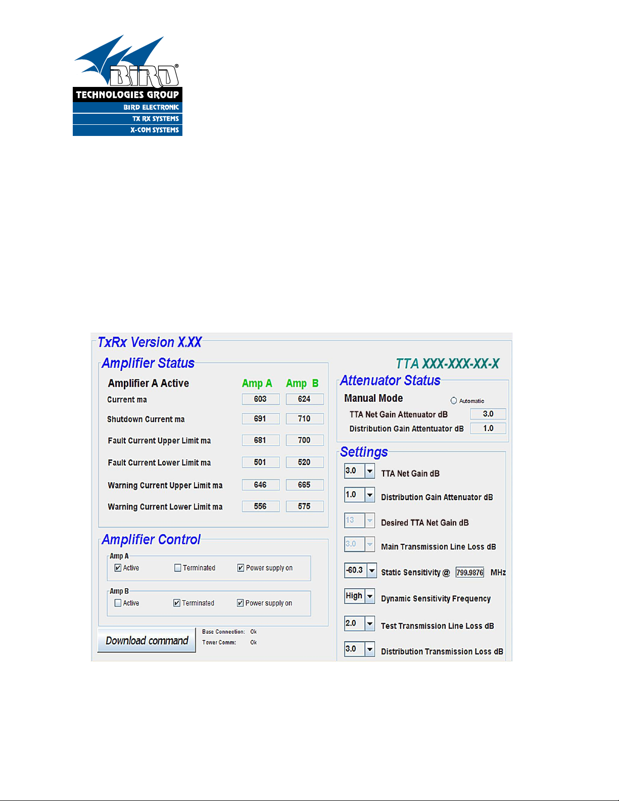
Figure 1: The web-based interface screen.
Ethernet Software Version
TTA System Model Number
The 429 series tower top amplifier system provides
front panel Ethernet connectivity that allows access
to a web-based interface for controlling and monitoring of amplifier currents, alarms, and attenuators. If you have not already done so, refer to
Appendix A in your TTA’s installation and operations manual for instructions on how to properly
connect your computer to the TTA’s front panel
LAN port.
Once you are properly connected to the TTA the
web-based interface screen will appear in your
web-browser’s window. Figure 1 shows the interface screen as it appears after you first connect.
The current Ethernet software version that is
loaded into your TTA is displayed in the uppermost
left corner while the model number of your system
appears in the uppermost right corner. The rest of
the display screen is divided into four functional
areas including;
Amplifier Status - provides continuously updated
status information on the two tower top amplifiers.
Amplifier Control - allows the user to interact with
the two tower top amplifiers by selecting which is
the active amp, terminating the amplifier inputs,
and turning on/off the power supply feed to the
amplifier.
Attenuator Status - displays the current setting of
both the TTA Net gain and distribution gain attenuators. Also allows the attenuator values to be either
manually entered by the user or automatically calculated.
Settings - the two uppermost registers are used to
manually adjust attenuator values. The next two
lowermost boxes are used when automatically calculating the TTA Net gain attenuator value. The
last four lowermost registers use to store values of
measured or estimated parameters.
TX RX Systems Inc. Manual 7-9440-2 11/17/08 Page 1
Page 8

Command Interface Button
Figure 2: Command Interface Button.
Figure 3: Amplifier Status Area.
These two column headings
change color to indicate
amplifier status
The lower left hand corner of the screen is the
command interface button which allows changes
you make on the web page interface screen to be
downloaded to the TTA, see Figure 2. The command interface button acts as a trigger sending any
changes you have made to the screen on to the
TTA only after the button is pressed. To the right of
the button are two status messages, one for the
base connection and one for the tower connection.
The command interface button is also used to display status information. The status messages
include the following;
DOWNLOAD COMMAND (black) - means there
are currently no changes to transmit to the TTA.
DOWNLOAD COMMAND (red) - means changes
have been made and will be transmitted to the TTA
once the button is pressed. After a download command is executed the button should turn black.
NO CONNECTION - indicates that communications have been interrupted between your computer and the TTA.
WAITING FOR UPDATE - This is a brief message
that appears after you send a download command
to the TTA. Once the new information is loaded
into the TTA’s memory this message will disappear.
NON-FUNCTIONAL OVERIDE - This message
appears whenever the TTA system is performing a
task that interrupts the normal flow of RF signals
through the system. An example would be if you
asked the system to terminate the active amplifier.
Refer to your TTA installation and operation manual under the section describing the TEST MODE
for a further discussion of non-functional modes.
BASE OVERRIDE - This message appears when
commands are loaded into the TTA at the front
panel that override commands being sent via the
web page interface. Commands entered into the
front panel have the priority.
Amplifier Status
This portion of the display shows the status of the
two tower top amplifiers A and B, refer to Figure 3.
The “AMP A” and “AMP B” column headings will be
displayed as either Green, Yellow, or Red. Green
TX RX Systems Inc. Manual 7-9440-2 11/17/08 Page 2
Page 9

indicates the amplifier is functioning normally, Yel-
Figure 4: Amplifier Control.
low indicates it’s in a warning state, and Red an
alarm state. The rightmost column heading indicates which amplifier is currently active (amplifier A
in the example shown in figure 3). In the six rows
under the headings there are current values displayed for each amplifier including;
CURRENT (ma) - this is the real-time current draw
of each amplifier and the same value that is displayed on the front panel display screen. This
value will update as required in real-time as long as
the webpage interface is active.
SHUTDOWN CURRENT (ma) - if the current draw
of the associated amplifier reaches this shutdown
point the supply current to the amplifier will be
turned off. This protects the tower top box circuitry
from excessive current draw.
FAULT CURRENT UPPER/LOWER (ma) - These
values are the alarm trip points for the respective
amplifier. If the amplifier current draw reaches this
point an alarm condition will be triggered.
WARNING CURRENT UPPER/LOWER (ma) These values are the warning trip points for the
respective amplifier. If the amplifier current draw
reaches this point a warning condition will be triggered.
The values for the shutdown, fault, and warning trip
points are calculated at the factory based on the
normal current draw for your tower top amplifiers.
The normal current draw may vary slightly between
different tower top boxes because of slight variations in manufacturing tolerances.
the screen. Remember to press the command
interface button to transmit your selection to the
TTA. Amplifier control choices include;
ACTIVE - this selection allows the user to determine which of the two tower top amplifiers will be
the active amp. The other amp will become inactive
by default.
TERMINATED - checking this box allows you to
terminate the input of that particular amplifier.
POWER SUPPLY ON - when checked the supply
current to the amplifier is on and when unchecked
it’s off.
Attenuator Status
This area displays the current settings for both the
TTA Net Gain attenuator and the Distribution gain
attenuator. The TTA Net Gain attenuation can be
derived as a manual input or it can be calculated
automatically. To use the automatic mode click the
circle next to the automatic label. Unclicking the circle will return you to the manual mode. Remember
to press the command interface button to transmit
any changes you make to the TTA. Figure 5
shows the Attenuator Status area of the screen.
When automatic has been selected the message
”AUTO MODE” will be shown on the MCU front
panel display when you scroll down the menu
choices to view the TTA Net Gain value. Refer to
manual 7-9439 “Installation and Operation manual
for the 429 Series Tower Top Amplifier System”.
Any changes that are made manually to the attenuator value from the TTA front panel will not be
allowed when the system is in the automatic mode.
Amplifier Control
This portion of the display allows the user to
manipulate the operation of the tower top amplifiers. Figure 4 shows the amplifier control section of
TX RX Systems Inc. Manual 7-9440-2 11/17/08 Page 3
Settings
The SETTINGS area of the interface screen allows
attenuator settings, desired TTA Net Gain, and
main transmission line loss values to be entered
Page 10

and saved. Figure 6 shows the SETTINGS area of
Figure 5: Attenuator Status.
Figure 6: Settings.
the screen.
The first value, TTA Net Gain, allows you to select
the TTA Net Gain attenuation value. This box will
be active whenever the attenuator status area is
set to manual and will be inactive when the attenuator status area is set to automatic. In the automatic mode the TTA Net Gain attenuation value is
computed automatically for you using the values
you have entered for “Desired TTA Net Gain” and
“Main Transmission Line Loss” as shown in figure
6. Remember to press the command interface button to transmit your selection to the TTA.
The second value, Distribution Gain Attenuator
allows you to program the distribution gain attenuation value into the TTA. Remember to press the
command interface button to transmit any changes
you make to the TTA.
The next two values, Desired TTA Net Gain and
Main Transmission Line Loss allow for automatic
calculation of the TTA Net Gain attenuator. These
boxes are active when the attenuator status area is
set to automatic and they are inactive when attenuator status is set to manual. Remember to press
the command interface button to transmit your
selection to the TTA.
The box for Test Transmission Line Loss provides
a place to store the loss value of your test transmission line.
The box for Distribution Transmission Loss provides a place to store the loss value of your distribution transmission line.
The Static Sensitivity box provides a place to store
your measured sensitivity value and the frequency
you made the measurement at.
The Dynamic Sensitivity Frequency box allows the
selection of Low, Medium, or High. In order to
check for sensitivity degradation, especially over
wide frequency ranges in combined 700/800 Mhz
systems, measurements at the lowest, midrange,
and highest frequencies are recommended.
TX RX Systems Inc. Manual 7-9440-2 11/17/08 Page 4
Page 11

Return Loss vs. VSWR
Return Loss VSWR
30 1.06
25 1.11
20 1.20
19 1.25
18 1.28
17 1.33
16 1.37
15 1.43
14 1.50
13 1.57
12 1.67
11 1.78
10 1.92
9 2.10
Watts to dBm
Watts dBm
300 54.8
250 54.0
200 53.0
150 51.8
100 50.0
75 48.8
50 47.0
25 44.0
20 43.0
15 41.8
10 40.0
5 37.0
4 36.0
3 34.8
2 33.0
1 30.0
dBm = 10log P/1mW
Where P = power (Watt)
Insertion Loss
Input Power (Watts)
50 75 100 125 150 200 250 300
3 25 38 50 63 75 100 125 150
2.5 28 42 56 70 84 112 141 169
2 32 47 63 79 95 126 158 189
1.5 35 53 71 88 106 142 177 212
1 40 60 79 99 119 159 199 238
.5 45 67 89 111 134 178 223 267
Output Power (Watts)
Insertion Loss
Free Space Loss
Distance (miles)
.25 .50 .75 1 2 5 10 15
150 68 74 78 80 86 94 100 104
220 71 77 81 83 89 97 103 107
460 78 84 87 90 96 104 110 113
860 83 89 93 95 101 109 115 119
940 84 90 94 96 102 110 116 120
1920 90 96 100 102 108 116 122 126
Free Space Loss (dB)
Free space loss = 36.6 + 20log D + 20log F
Where D = distance in miles and F = frequency in MHz
Frequency (MHz)
Page 12

SYSTEMS
SYSTEMS
INC.
INC.
TX RX Systems Inc. 8625 Industrial Parkway, Angola, NY 14006 Tel: 716-549-4700 Fax: 716-549-4772 sales@txrx.com www.txrx.com
 Loading...