

Page 1

Wattcher® monitor/alarm
Models 3170B
©
Copyright 2011
Instruction Book Part Number 920-3170AS Rev. D
by Bird Electronic Corporation
Wattcher is a registered trademark
of Bird Electronic Corporation
Page 2

Page 3

Safety Precautions
The following are general safety precautions that are not necessarily related to any specific
part or procedure, and do not necessarily appear elsewhere in this publication. These precautions must be thoroughly understood and apply to all phases of operation and maintenance.
WARNING
Keep Away From Live Circuits
Operating Personnel must at all times observe general safety precautions. Do not replace
components or make adjustments to the inside of the test equipment with the high voltage
supply turned on. To avoid casualties, always remove power.
WARNING
Shock Hazard
Do not attempt to remove the RF transmission line while RF power is present.
WARNING
Do Not Service Or Adjust Alone
Under no circumstances should any person reach into an enclosure for the purpose of
service or adjustment of equipment except in the presence of someone who is capable of
rendering aid.
WARNING
Safety Earth Ground
An uniterruptible earth safety ground must be supplied from the main power source to test
instruments. Grounding one conductor of a two conductor power cable is not sufficient
protection. Serious injury or death can occur if this grounding is not properly supplied.
WARNING
Resuscitation
Personnel working with or near high voltages should be familiar with modern methods of
resuscitation.
WARNI NG
Remove Power
Observe general safety precautions. Do not open the instrument with the power on.
Safety Symbols
WARNING
Warning notes call attention to a procedure, which if not correctly performed could result in
personal injury.
CAUTION
Caution notes call attention to a procedure, which if not correctly performed could result in
damage to the instrument.
Note: Calls attention to supplemental information.
i
Page 4

Warning Statements
The following safety warnings appear in the text where there is danger to operating and maintenance personnel and are repeated here for emphasis.
WARNING
Do not use electrically conductive tools for calibration when the front panel is removed.
Damage to the unit and or the possibility of electrical shock exists.
See page 10.
WARNING
Become thoroughly familiar with modern methods of resuscitation before working near
high voltage sources.
See page 15.
WARNING
Shock hazard. Always turn off AC power before removing any equipment panels.
See page 15.
WARNING
Disconnect this unit from ac power source before any disassembly for cleaning, repair or
replacement procedures. The potential for electrical shock exists.
See pages 15 and 20.
WARNING
When using dry cleaning solvents, provide adequate ventilation and observe normal safety
precautions. Many dry cleaning agents emit toxic fumes that may be harmful to your health
if inhaled.
See page 15.
ii
Page 5

Caution Statements
The following equipment cautions appear in the text whenever the equipment is in danger of
damage and are repeated here for emphasis.
CAUTION
Be sure the 115/230 voltage selector switch on the rear panel is set to the proper line
voltage before AC power is applied.
See page 9.
CAUTION
Do not bend this contact finger when cleaning. The position of this contact is some what
critical. If it is out too far the element will not enter the socket and if it is in too far, it will not
make contact with the button on the element. For contact adjustments, refer to "Adjusting
the Element Wiper Contact" on page 18.
See page 15.
CAUTION
If the element cannot be fully inserted into the socket, do not force it. You might
damage the element wiper contact.
See page 18.
CAUTION
Be careful not to bend element wiper contact out too far as to interfere with insertion
of the elements.
See page 18.
iii
Page 6

Safety Statements
USAGE
ANY USE OF THIS INSTRUMENT IN A MANNER NOT SPECIFIED BY THE
MANUFACTURER MAY IMPAIR THE INSTRUMENT’S SAFETY PROTECTION.
USO
EL USO DE ESTE INSTRUMENTO DE MANERA NO ESPECIFICADA POR EL
FABRICANTE, PUEDE ANULAR LA PROTECCIÓN DE SEGURIDAD DEL
INSTRUMENTO.
BENUTZUNG
WIRD DAS GERÄT AUF ANDERE WEISE VERWENDET ALS VOM HERSTELLER
BESCHRIEBEN, KANN DIE GERÄTESICHERHEIT BEEINTRÄCHTIGT WERDEN.
UTILISATION
TOUTE UTILISATION DE CET INSTRUMENT QUI N’EST PAS EXPLICITEMENT
PRÉVUE PAR LE FABRICANT PEUT ENDOMMAGER LE DISPOSITIF DE
PROTECTION DE L’INSTRUMENT.
IMPIEGO
QUALORA QUESTO STRUMENTO VENISSE UTILIZZATO IN MODO DIVERSO DA
COME SPECIFICATO DAL PRODUTTORE LA PROZIONE DI SICUREZZA
POTREBBE VENIRNE COMPROMESSA.
iv
Page 7

SERVICE
SERVICING INSTRUCTIONS ARE FOR USE BY SERVICE - TRAINED
PERSONNEL ONLY. TO AVOID DANGEROUS ELECTRIC SHOCK, DO NOT
PERFORM ANY SERVICING UNLESS QUALIFIED TO DO SO.
SERVICIO
LAS INSTRUCCIONES DE SERVICIO SON PARA USO EXCLUSIVO DEL
PERSONAL DE SERVICIO CAPACITADO. PARA EVITAR EL PELIGRO DE
DESCARGAS ELÉCTRICAS, NO REALICE NINGÚN SERVICIO A MENOS QUE
ESTÉ CAPACITADO PARA HACERIO.
WARTUNG
ANWEISUNGEN FÜR DIE WARTUNG DES GERÄTES GELTEN NUR FÜR
GESCHULTES FACHPERSONAL.
ZUR VERMEIDUNG GEFÄHRLICHE, ELEKTRISCHE SCHOCKS, SIND
WARTUNGSARBEITEN AUSSCHLIEßLICH VON QUALIFIZIERTEM
SERVICEPERSONAL DURCHZUFÜHREN.
ENTRENTIEN
L’EMPLOI DES INSTRUCTIONS D’ENTRETIEN DOIT ÊTRE RÉSERVÉ AU
PERSONNEL FORMÉ AUX OPÉRATIONS D’ENTRETIEN. POUR PRÉVENIR UN
CHOC ÉLECTRIQUE DANGEREUX, NE PAS EFFECTUER D’ENTRETIEN SI L’ON
N’A PAS ÉTÉ QUALIFIÉ POUR CE FAIRE.
ASSISTENZA TECNICA
LE ISTRUZIONI RELATIVE ALL’ASSISTENZA SONO PREVISTE ESCLUSIVAMENTE
PER IL PERSONALE OPPORTUNAMENTE ADDESTRATO. PER EVITARE
PERICOLOSE SCOSSE ELETTRICHE NON EFFETTUARRE ALCUNA RIPARAZIONE
A MENO CHE QUALIFICATI A FARLA.
v
Page 8

CONNECT INTERLOCK TO TRANSMITTER BEFORE OPERATING.
BRANCHER LE VERROUILLAGE À L'ÉMETTEUR AVANT EMPLOI.
CONECTE EL INTERBLOQUEO AL TRANSMISOR ANTES DE LA OPERACION.
VOR INBETRIEBNAHME VERRIEGELUNG AM SENDER ANSCHLIESSEN.
PRIMA DI METTERE IN FUNZIONE L'APPARECCHIO, COLLEGARE IL
DISPOSITIVO DI BLOCCO AL TRASMETTITORE.
vi
Page 9

About This Manual
This manual covers the operating and maintenance instructions for the following models:
3170B 3170B400
3171B 3171B020
Changes to this Manual
We have made every effort to ensure this manual is accurate. If you discover any errors, or if you
have suggestions for improving this manual, please send your comments to our Solon, Ohio factory. This manual may be periodically updated. When inquiring about updates to this manual
refer to the part number and revision on the title page.
Terminology
There are some unique terms used throughout this literature. They are defined here to clarify
any misunderstanding.
Introduction — Describes the features, lists equipment supplied and optional equipment, and
provides power-up instructions.
Theory of Operation — Describes how the load resistor works.
Installation — Describes the power supply and load connection instructions.
Operating Instructions — Describes the base level operation instructions.
Maintenance — Lists routine maintenance tasks as well as troubleshooting for common prob-
lems. Specifications and parts information are also included.
vii
Page 10

viii
Page 11

Table of Contents
Safety Precautions . . . . . . . . . . . . . . . . . . . . . . . . . . . . . . . . . . . . . . . . . . . . . . . . . . . . . . . . . i
Safety Symbols . . . . . . . . . . . . . . . . . . . . . . . . . . . . . . . . . . . . . . . . . . . . . . . . . . . . . . . . . . . . . . . . . . . . . i
Warning Statements . . . . . . . . . . . . . . . . . . . . . . . . . . . . . . . . . . . . . . . . . . . . . . . . . . . . . . . . . . . . . . . . .ii
Caution Statements . . . . . . . . . . . . . . . . . . . . . . . . . . . . . . . . . . . . . . . . . . . . . . . . . . . . . . . . . . . . . . . . iii
Safety Statements . . . . . . . . . . . . . . . . . . . . . . . . . . . . . . . . . . . . . . . . . . . . . . . . . . . . . . . . . . . . . . . . . . iv
About This Manual . . . . . . . . . . . . . . . . . . . . . . . . . . . . . . . . . . . . . . . . . . . . . . . . . . . . . . . .vii
Changes to this Manual . . . . . . . . . . . . . . . . . . . . . . . . . . . . . . . . . . . . . . . . . . . . . . . . . . . . . . . . . . . . .vii
Terminology . . . . . . . . . . . . . . . . . . . . . . . . . . . . . . . . . . . . . . . . . . . . . . . . . . . . . . . . . . . . . . . . . . . . . . .vii
Chapter 1 Introduction . . . . . . . . . . . . . . . . . . . . . . . . . . . . . . . . . . . . . . . . . . . . . . . . . . . . .1
General . . . . . . . . . . . . . . . . . . . . . . . . . . . . . . . . . . . . . . . . . . . . . . . . . . . . . . . . . . . . . . . . . . . . . . . . . . 1
Items Supplied . . . . . . . . . . . . . . . . . . . . . . . . . . . . . . . . . . . . . . . . . . . . . . . . . . . . . . . . . . . . . . . . . . . . . 1
Items Required . . . . . . . . . . . . . . . . . . . . . . . . . . . . . . . . . . . . . . . . . . . . . . . . . . . . . . . . . . . . . . . . . . . . 1
Optional Accessories . . . . . . . . . . . . . . . . . . . . . . . . . . . . . . . . . . . . . . . . . . . . . . . . . . . . . . . . . . . . . . . . 1
Purpose and Function . . . . . . . . . . . . . . . . . . . . . . . . . . . . . . . . . . . . . . . . . . . . . . . . . . . . . . . . . . . . . . . 2
Functional Description . . . . . . . . . . . . . . . . . . . . . . . . . . . . . . . . . . . . . . . . . . . . . . . . . . . . . . . . . . . . . . 3
Enclosures . . . . . . . . . . . . . . . . . . . . . . . . . . . . . . . . . . . . . . . . . . . . . . . . . . . . . . . . . . . . . . . . . . . . . 3
Front Panel . . . . . . . . . . . . . . . . . . . . . . . . . . . . . . . . . . . . . . . . . . . . . . . . . . . . . . . . . . . . . . . . . . . . 3
Chapter 2 Theory of Operation . . . . . . . . . . . . . . . . . . . . . . . . . . . . . . . . . . . . . . . . . . . . . .7
Input Signal . . . . . . . . . . . . . . . . . . . . . . . . . . . . . . . . . . . . . . . . . . . . . . . . . . . . . . . . . . . . . . . . . . . . . . . 7
Adjustment . . . . . . . . . . . . . . . . . . . . . . . . . . . . . . . . . . . . . . . . . . . . . . . . . . . . . . . . . . . . . . . . . . . . . . . 7
Operations . . . . . . . . . . . . . . . . . . . . . . . . . . . . . . . . . . . . . . . . . . . . . . . . . . . . . . . . . . . . . . . . . . . . . . . . 7
Reset . . . . . . . . . . . . . . . . . . . . . . . . . . . . . . . . . . . . . . . . . . . . . . . . . . . . . . . . . . . . . . . . . . . . . . . . . . . . 7
Chapter 3 Preparation for Use . . . . . . . . . . . . . . . . . . . . . . . . . . . . . . . . . . . . . . . . . . . . . . .9
General . . . . . . . . . . . . . . . . . . . . . . . . . . . . . . . . . . . . . . . . . . . . . . . . . . . . . . . . . . . . . . . . . . . . . . . . . . 9
Unpacking and Inspection . . . . . . . . . . . . . . . . . . . . . . . . . . . . . . . . . . . . . . . . . . . . . . . . . . . . . . . . . . . 9
Installation . . . . . . . . . . . . . . . . . . . . . . . . . . . . . . . . . . . . . . . . . . . . . . . . . . . . . . . . . . . . . . . . . . . . . . . . 9
Mounting . . . . . . . . . . . . . . . . . . . . . . . . . . . . . . . . . . . . . . . . . . . . . . . . . . . . . . . . . . . . . . . . . . . . . . 9
Models 3170B and 3170B400 . . . . . . . . . . . . . . . . . . . . . . . . . . . . . . . . . . . . . . . . . . . . . . . . . . . . . 9
Models 3171B and 3171B020 . . . . . . . . . . . . . . . . . . . . . . . . . . . . . . . . . . . . . . . . . . . . . . . . . . . . 10
Initial Setup . . . . . . . . . . . . . . . . . . . . . . . . . . . . . . . . . . . . . . . . . . . . . . . . . . . . . . . . . . . . . . . . . . . . . . 10
Preparation . . . . . . . . . . . . . . . . . . . . . . . . . . . . . . . . . . . . . . . . . . . . . . . . . . . . . . . . . . . . . . . . . . . 10
Checking the LED Light . . . . . . . . . . . . . . . . . . . . . . . . . . . . . . . . . . . . . . . . . . . . . . . . . . . . . . . . 10
Removing the Faceplate . . . . . . . . . . . . . . . . . . . . . . . . . . . . . . . . . . . . . . . . . . . . . . . . . . . . . . . 10
Adjust Set-Points . . . . . . . . . . . . . . . . . . . . . . . . . . . . . . . . . . . . . . . . . . . . . . . . . . . . . . . . . . . . . . . 11
Active Forward Monitor Setup . . . . . . . . . . . . . . . . . . . . . . . . . . . . . . . . . . . . . . . . . . . . . . . . . . . 12
Dip Switch Settings . . . . . . . . . . . . . . . . . . . . . . . . . . . . . . . . . . . . . . . . . . . . . . . . . . . . . . . . . . . . . 12
Chapter 4 Operating Instructions . . . . . . . . . . . . . . . . . . . . . . . . . . . . . . . . . . . . . . . . . . .13
General . . . . . . . . . . . . . . . . . . . . . . . . . . . . . . . . . . . . . . . . . . . . . . . . . . . . . . . . . . . . . . . . . . . . . . . . . . 13
RF Power Measurement . . . . . . . . . . . . . . . . . . . . . . . . . . . . . . . . . . . . . . . . . . . . . . . . . . . . . . . . . . . . 13
Chapter 5 Maintenance . . . . . . . . . . . . . . . . . . . . . . . . . . . . . . . . . . . . . . . . . . . . . . . . . . . .15
Safety Considerations . . . . . . . . . . . . . . . . . . . . . . . . . . . . . . . . . . . . . . . . . . . . . . . . . . . . . . . . . . . . . . 15
Preventive Maintenance . . . . . . . . . . . . . . . . . . . . . . . . . . . . . . . . . . . . . . . . . . . . . . . . . . . . . . . . . . . . 15
Cleaning . . . . . . . . . . . . . . . . . . . . . . . . . . . . . . . . . . . . . . . . . . . . . . . . . . . . . . . . . . . . . . . . . . . . . . 15
Front Panel . . . . . . . . . . . . . . . . . . . . . . . . . . . . . . . . . . . . . . . . . . . . . . . . . . . . . . . . . . . . . . . . . . 15
Line Section . . . . . . . . . . . . . . . . . . . . . . . . . . . . . . . . . . . . . . . . . . . . . . . . . . . . . . . . . . . . . . . . . 15
Customer Service . . . . . . . . . . . . . . . . . . . . . . . . . . . . . . . . . . . . . . . . . . . . . . . . . . . . . . . . . . . . . . . . . 16
Troubleshooting . . . . . . . . . . . . . . . . . . . . . . . . . . . . . . . . . . . . . . . . . . . . . . . . . . . . . . .
viii
. . . . . . . . . . . 17
Page 12

Maintenance Procedures . . . . . . . . . . . . . . . . . . . . . . . . . . . . . . . . . . . . . . . . . . . . . . . . . . . . . . . . . . . 18
Adjusting the Element Wiper Contact . . . . . . . . . . . . . . . . . . . . . . . . . . . . . . . . . . . . . . . . . . . . . . 18
Fuse Drawer/Fuse Replacement . . . . . . . . . . . . . . . . . . . . . . . . . . . . . . . . . . . . . . . . . . . . . . . . . . 19
Changing Fuse Drawer for 230V Operation . . . . . . . . . . . . . . . . . . . . . . . . . . . . . . . . . . . . . . . . 19
Replacing Blown Fuse . . . . . . . . . . . . . . . . . . . . . . . . . . . . . . . . . . . . . . . . . . . . . . . . . . . . . . . . . 20
Replacing Fuse for External DC Input Voltage . . . . . . . . . . . . . . . . . . . . . . . . . . . . . . . . . . . . . . 20
Meter Replacement . . . . . . . . . . . . . . . . . . . . . . . . . . . . . . . . . . . . . . . . . . . . . . . . . . . . . . . . . . . . 21
Storing . . . . . . . . . . . . . . . . . . . . . . . . . . . . . . . . . . . . . . . . . . . . . . . . . . . . . . . . . . . . . . . . . . . . . . . . . . 21
Repackaging . . . . . . . . . . . . . . . . . . . . . . . . . . . . . . . . . . . . . . . . . . . . . . . . . . . . . . . . . . . . . . . . . . . . . . 21
Replacement Parts List . . . . . . . . . . . . . . . . . . . . . . . . . . . . . . . . . . . . . . . . . . . . . . . . . . . . . . . . . . . . . 22
Line Section Cable Assemblies . . . . . . . . . . . . . . . . . . . . . . . . . . . . . . . . . . . . . . . . . . . . . . . . . . . . 22
Meter Cable Assemblies . . . . . . . . . . . . . . . . . . . . . . . . . . . . . . . . . . . . . . . . . . . . . . . . . . . . . . . . . 22
Specifications . . . . . . . . . . . . . . . . . . . . . . . . . . . . . . . . . . . . . . . . . . . . . . . . . . . . . . . . . . . . . . . . . . . . . 23
Element Tables . . . . . . . . . . . . . . . . . . . . . . . . . . . . . . . . . . . . . . . . . . . . . . . . . . . . . . . . . . . . . . . . . . . 24
7/8" Line Section . . . . . . . . . . . . . . . . . . . . . . . . . . . . . . . . . . . . . . . . . . . . . . . . . . . . . . . . . . . . . . . 24
Line Section . . . . . . . . . . . . . . . . . . . . . . . . . . . . . . . . . . . . . . . . . . . . . . . . . . . . . . . . . . . . . . . . . . 26
Appendix 1 Difference Data Sheet . . . . . . . . . . . . . . . . . . . . . . . . . . . . . . . . . . . . . . . . . . . 29
Appendix 1 User Applications and Wiring . . . . . . . . . . . . . . . . . . . . . . . . . . . . . . . . . . . . 31
Connector Assignment . . . . . . . . . . . . . . . . . . . . . . . . . . . . . . . . . . . . . . . . . . . . . . . . . . . . . . . . . . . . . 31
Active Forward Monitor (AFM) Input . . . . . . . . . . . . . . . . . . . . . . . . . . . . . . . . . . . . . . . . . . . . . . . . . 32
Dry Contact Closure . . . . . . . . . . . . . . . . . . . . . . . . . . . . . . . . . . . . . . . . . . . . . . . . . . . . . . . . . . . . 32
Logic “1" Closure . . . . . . . . . . . . . . . . . . . . . . . . . . . . . . . . . . . . . . . . . . . . . . . . . . . . . . . . . . . . . . . 32
Confirm Output . . . . . . . . . . . . . . . . . . . . . . . . . . . . . . . . . . . . . . . . . . . . . . . . . . . . . . . . . . . . . . . . . . . 33
Relay Control . . . . . . . . . . . . . . . . . . . . . . . . . . . . . . . . . . . . . . . . . . . . . . . . . . . . . . . . . . . . . . . . . . 33
LED Indicator . . . . . . . . . . . . . . . . . . . . . . . . . . . . . . . . . . . . . . . . . . . . . . . . . . . . . . . . . . . . . . . . . . 33
Reset Input . . . . . . . . . . . . . . . . . . . . . . . . . . . . . . . . . . . . . . . . . . . . . . . . . . . . . . . . . . . . . . . . . . . . . . . 34
Remote Contact Reset . . . . . . . . . . . . . . . . . . . . . . . . . . . . . . . . . . . . . . . . . . . . . . . . . . . . . . . . . . 34
Remote Metering . . . . . . . . . . . . . . . . . . . . . . . . . . . . . . . . . . . . . . . . . . . . . . . . . . . . . . . . . . . . . . . . . 34
DC Power Supply Connections . . . . . . . . . . . . . . . . . . . . . . . . . . . . . . . . . . . . . . . . . . . . . . . . . . . . . . . 35
Limited Warranty . . . . . . . . . . . . . . . . . . . . . . . . . . . . . . . . . . . . . . . . . . . . . . . . . . . . . . . . . 37
ix
Page 13

Chapter 1 Introduction
General
This publication refers to the Model 3170B which is a member of the Bird Model 3170B Series of High Speed Wattcher RF Monitors. Models included in the series are listed in Table 1-1. All models will generally be referred to as a
Wattcher unit through out this manual.
The information in this instruction book pertains to all models except noted differences referred to in the text and in
the "Difference Data Sheet" on page 29.
Table 1-1 Various Models
Model Number Power Range Comments
3170B 100 mW - 10 kW Built in Line Section
3170B400 100 mW - 10 kW Built in Line Section.
No reset or audible
alarm function,
Extended AFM timing.
3171B 250 W - 100 kW Uses External Line
3171B020 300 W - 60 kW
Section
Items Supplied
2
Qty Description
1 3170B Series High Speed Wattcher
1 AC Power Cord
1 Fuse drawer for 230V operation
2 Fuses for 230 V operation
Items Required
For power monitoring each port must contain a plug-in element. The determination of elements required is based
on line section size, frequency band of use and RF power level range. Refer to "Element Tables" on page 24.
Optional Accessories
Bird offers a larger number of cable assembly lengths for remote line sections and meters. For different power or
frequency requirements see “Element Table Selection” on page 24.
1
Page 14

Purpose and Function
The Model 3170B Series High Speed Wattcher unit is a two channel power monitoring system for use in 50 ohm
coaxial transmission lines. Adjustable set points allow user to preset maximum reflected and minimum forward
power trip points.
Activated audible/visual alarms indicate an erroneous condition present on the transmission line. Corrective action
can then be followed to either protect transmission equipment or restore transmission line to operational characteristics. This power monitoring capability is accomplished through the use of a dual port 50 ohm insertion type line
section. Each port must contain a standard Bird Electronic Corporation plug-in element. Usually elements with a ten
to one ratio is recommended for the forward and reverse power levels.
The Wattcher monitoring system also provides additional terminal connections for user specific applications. For
details and wiring information, see “User Applications and Wiring” on page 31.
2
Page 15
Functional Description
3
4
2
1
Enclosures
The Wattcher Monitor’s internal circuitry is enclosed in an aluminum housing. This housing is mounted to a standard
19-inch panel for rack mount applications.
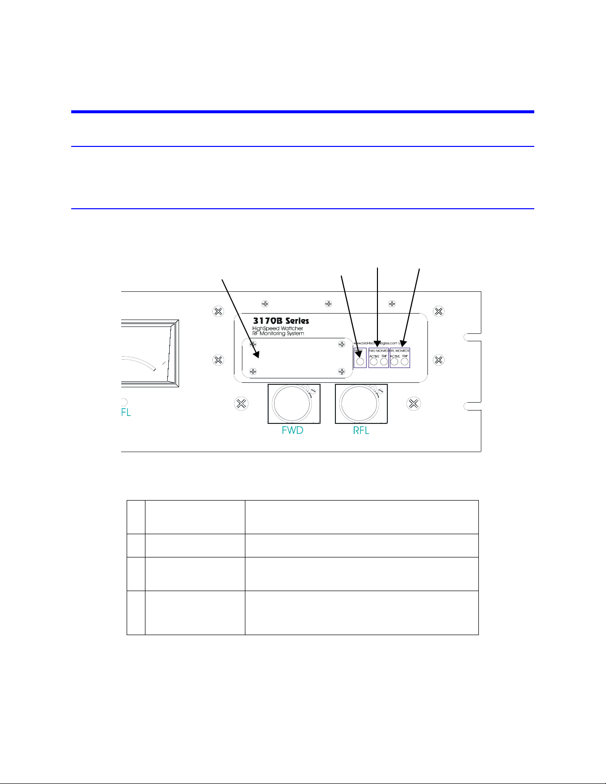
Front Panel
Figure 1 Front Panel
Table 1-2 Front Panel
1 Alarm/Setpoint
Faceplate
2 Reset This push button resets the monitoring system to normal
3 Forward Monitor Active LED—Indicates forward power is being monitored
4 Reflected Monitor Active LED—Indicates reflected power is being
If forward or reflected power set points are exceeded an
audible alarm is sounded. The alarm works in conjuction
with error status indicator reflecting failure conditions.
operation after an error condition has been corrected.
and an error condition will be indicated upon failure.
Trip LED—Indicates error condition has occurred.
monitored and an error condition will be indicated upon
failure.
Trip LED—Indicates error condition has occurred.
3
Page 16

Figure 2 Rear Panel
1
3
2
5
6
7
4
Table 1-3 Rear Panel
1 AC Receptacle Provides a means of supplying AC line power to
Wattcher control unit.
2 AC Line Fuse Slow-blow fuse, provides circuit protection from
excessive surge inline power or in the event of
component failure.
3 Line Voltage Selector
Switch
4 Power/Alarm/Remote
Terminal Strip
5 Remote Meter
Connections
6RF Power Input
Connections
(from line section)
7 Meter Connections Connectors for front panel main meters. Can also be
Determines line voltage operation (115 or 230VAC).
Provides connection for external DC supply, auxiliary
alarm input and output, reset input and output, remote
confirm output and auxiliary 5V output. See “User
Applications and Wiring” on page 31.
Extra meter connections for remote meters. For details
on connecting remote meters see “User Applications
and Wiring” on page 31. Levels: 1.038V full scale. Use
33.2k resistor in series with standard Bird 30mA meters.
Female BNC connectors, provide means of connecting
sampled RF power. Forward and Reflected power
connectors are labeled as such. Levels: 30μA full scale
into 1400Ω (42mV). May be overranged to 100mV.
used to connect remote meters. Levels: 30mA full scale
into 1400 ohm (42mV).
4
Page 17

Line Section
AC Receptacle
RF Input
Connector
RF Output
Connector
1/4”
(6mm)
18-5/32”
(461mm)
19”
(483mm)
2-1/4”
(57mm)
1-31/64”
(38mm)
5-7/32”
(133mm)
Meters
6-7/16”
(164mm)
Figure 3 Models 3170B and 3170B400
5
Page 18

Remote Line Section
AC Receptacle
RF Output
Connector
RF Input
Connector
1/4”
(6mm)
18-5/32”
(461mm)
19”
(483mm)
2-1/4”
(57mm)
1-31/64”
(38mm)
5-7/32”
(133mm)
~
6-7/16”
(164mm)
RFL FWD
Meters
Figure 4 Models 3171B and 3171B020
6
Page 19

Chapter 2 Theory of Operation
Input Signal
Direct current signals representing operating power levels are brought into the RF monitor from the sensing elements through the rear panel jacks labeled RF Power Input Forward and Reflected. These currents are shunted to
ground through 1400 ohm resistors. The voltage developed across these resistors is amplified by a pair of operational amplifiers to approximately one volt (meter full scale).
The drive current to the main indicating meters is taken from the amplifier outputs through series resistors of 33.2k
ohm each. The drive voltage for remote meters also comes from the amplifier outputs and is buffered by a pair of
op-amps configured for unity gain. This protects the 3170B/71B circuitry against accidental shorting of the remote
meter line.
Adjustment
The calibrate/operate switch and the two reference potentiometer allow the user to substitute an adjustable current in place of the signals from the sensing elements to facilitate adjustment of the set-points.
The three set-point potentiometer (forward, reflected, and confirm) provide DC voltages which are compared to the
amplifier outputs by three comparators.
The LED to the left of each potentiometer indicates whether the incoming signal is higher (LED ON) or lower (LED OFF)
than the set-point of the potentiometer.
Operations
The output of the confirm comparator goes directly to the confirm output drive transistors. The output of the
reflected comparator goes directly to the alarm circuitry and to the reflector monitor tripped LED latch. The output
of the forward comparator is gated by the activate forward monitor signal AFM before going to the alarm circuitry
and LED latch.
In other words, the signal is blocked if the activate forward monitor signal is not present. The AFM signal passes
through a delay circuit before reaching the gate. The purpose of the delay is to allow for any delays in the user’s equipment between the initial excitation of the carrier ON signal and the presence of power on the transmission line.
Reset
The reset signal clears the horn latch and the two trip LED latches. This signal can come from three sources: the push
button switch on the front panel, the rear panel input/output, or from the power-up reset capacitor when the
device is first turned on or after a power interruption.
7
Page 20

8
Page 21

Chapter 3 Preparation for Use
General
The series 3170B High-Speed Wattcher RF Monitoring System was designed for indoor use. This section contains
information on unpacking and inspection; and preparing the Wattcher Unit for use.
Unpacking and Inspection
1. Carefully inspect shipping container for signs of damage. If damage is noticed, do not
unpack the unit. Immediately notify the shipping carrier and Bird Electronic Corporation.
2. If container is not damaged, unpack the unit. Save shipping materials for repackaging.
3. Inspect unit for visual signs of damage. Immediately notify the shipping carrier and
Bird Electronic Corporation of equipment damage.
Installation
Mounting
The Model 3170B Series High Speed Wattcher System is intended for rack panel mounting. The panels are designed to fit
ASA standard 19 inch size “C” racks.
The Models 3170B and 3170B400 are fully self-contained units with the RF line section mounted on the panel. The
Models 3171B and 3171B020, however, utilize remotely mounted line sections.
CAUTION
Be sure the 115/230 voltage selector switch on the rear panel is set to the proper line
voltage before AC power is applied.
Note: For installation of Models 3170B and 3170B400 refer to Figure 3 on page 5. For installation of Models 3171B and 3171B020, refer to Figure 4 on page 6.
Models 3170B and 3170B400
Note: If the back of the unit is not accessible from the rear of the rack mount, any connections to the unit
must be made before the panel is secured in place.
1. Connect the RF coaxial transmission line to the line section.
2. Ensure the 115/230 line voltage switch is in the proper position for the voltage supplied.
Note: 3170B series Wattcher is shipped with a fuse and fuse drawer set for
115V operations. For 230V operations, see “Changing Fuse Drawer for 230V
Operation” on page 19.
3. Connect the AC power cord from the Wattcher unit to an appropriate source.
Note: Make DC power connections if needed.
4. Secure the panel to the rack with appropriate fasteners.
9
Page 22

Models 3171B and 3171B020
Remove
these
screws
1. Insert the line section in the coaxial RF coaxial transmission line.
2. Connect the DC cable to the line section.
3. Run the DC cable to the rack console unit.
4. Ensure that the 115/230 line voltage switch is in the correct position for the voltage
supplied.
5. Connect the AC power cord from the Wattcher unit to an appropriate source.
6. Secure the panel to the rack mount using appropriate fasteners.
Initial Setup
Preparation
Do not use electrically conductive tools for calibration when the front panel is
Damage to the unit and or the possibility of electrical shock exists.
Note: If the back of the unit is not accessible from the rear of the rack mount,
all connections to the unit must be made before the panel is secured in place.
Note: 3170B series Wattcher is shipped with a fuse and fuse drawer set for
115V operations. For 230V operations, see “Changing Fuse Drawer for 230V
Operation” on page 19..
Note: Make DC power connections if needed.
WARNING
removed.
Checking the LED Light
When either AC or DC power is applied to the unit, the yellow reflected monitor active LED should light. If this light
does not come on, disconnect the power cord and refer to Chapter 5, Maintenance. With the yellow reflected monitor active LED lit, signifying power is ON and the unit is operational, proceed with the initial setup be low.
Removing the Faceplate
1. Remove the four screws found in the corners of the faceplate.
Note: This exposes the circuit board on which the calibration controls are
located.
2. Set the CALIBRATE/OPERATE switch to the calibrate position (to the left).
Figure 5 Face Plate Removal
10
Page 23

Figure 6 Controls and Indicators
1
2
3
4
5
6
7
LED’s
Calibrate
Operate
Switch
1 Calibrate/Operate Switch
2 Forward Reference Adjustment Potentiometer
3 Reflected Reference Adjustment Potentiometer
4 Forward Set Point Potentiometer
5 Reflected Set Point Potentiometer
6 Confirm Set Point Potentiometer
7 Forward Monitor Active Delay Dip Switch
Adjust Set-Points
1. Set the CALIBRATE/OPERATE switch to the CALIBRATE position (to the left).
2. Do one or more of the following:
• Set the Forward Power Level Alarm Trip Point
a. Adjust the forward reference potentiometer to set the meter to indicate the
power level at which the forward alarm is to be tripped.
b. Adjust the forward set-point potentiometer until the miniature LED to the left
of the potentiometer is just at the transition from off to on.
Note: Turning the potentiometer clockwise will raise the set-point and turn the
light off.
• Set the Reflected Power Level Alarm Trip Point
a. Set the reflected trip point, on the reflected potentiometers, in a similar
manner to the forward trip point. See “Set the Forward Power Level Alarm
Trip Point” on page 11.
Note: The alarm will trip during this operation. It can be reset when completed.
• Set the Confirm Set-Point
a. Adjust the forward reference potentiometer to set the trip point level.
b. Adjust the confirm set-point potentiometer until the miniature LED to the left of
the potentiometer is just at the transition from off to on.
Note: If the confirm output is not used, it is not necessary to adjust the confirm
set-point potentiometer.
3. Return the CALIBRATE/OPERATE switch to the OPERATE position (to the right).
11
Page 24

Active Forward Monitor Setup
Note: Internal circuitry sets Active Forward Monitor (AFM) input to a high state. This inhibits monitoring of
forward power on transmission line. To monitor forward power, follow the steps below.
1. Connect AFM input to ground by hardwiring terminal strip position 10 (AFM input) to
position 7 (ground).
2. Select the appropriate delay (see Table 1-4).
Note: This delay allows transmitting equipment to reach acceptable power
output before being monitored by forward channel for low power condition.
3. Do one of the following:
• If the delay in the user’s equipment is known: the AFM should be set to the
same delay plus a minimum of 25 percent safety factor.
• If the delay in the user’s equipment is unknown:
a. Set the AFM to progressively shorter delays until switching on the carrier
causes the FWD monitor to trip when the user’s equipment is known to be
working properly.
b. Add a 25 percent safety factor to the delay indicated by the switch setting
and set the delay to that setting.
Note: That the disabling of the forward monitor is virtually instantaneous
when the AFM signal is removed and is unaffected by the switch settings.
Dip Switch Settings
Dip Switch bank SW2 is used to select AFM delay time. Refer to Figure 7 for correct on/off position. Ensure the
switches or set fully on or off.
In Table 1-4 the delay times are listed in the appropriate row & column for the switch set tings.
Figure 7 SO2 Dip Switch
12
Table 1-4 Setting AFM Delay
SW6 ON
SW5 OFF
SW4 OFF
SW1 SW2 SW3 3170B400 All
models
ON ON ON 7.1ms 71μs 71ms 710μs 710ms 7.1ms
OFF ON ON 8.3ms 83μs 83ms 830μs 830ms 8.3ms
ON OFF ON 10.0ms 100μs 100ms 1ms 1s 10.0ms
OFF OFF ON 12.1ms 121μs 121ms 1.21ms 1.21s 12.1ms
ON ON OFF 16.7ms 167μs 167ms 1.67ms 1.67s 16.7ms
OFF ON OFF 25.0ms 250μs 250ms 2.5ms 2.5s 25ms
ON OFF OFF 50.0ms 500μs 500ms 5.0ms 5.0s 50ms
SW6 OFF
SW5 ON
SW4 OFF
3170B400 All other
models
SW6 OFF
SW5 OFF
SW4 ON
3170B400 All other
models
Page 25

Chapter 4 Operating Instructions
General
When the unit is installed and connected to a transmitter for remote monitoring, metering, or external alarms and functions as your installation requires, operator attention is not required. The equipment will completely monitor a transmitter’s operation. The only time operating personnel will be necessary is to reset the unit if it has not been wired for
automatic or remote reset. Refer to "User Applications and Wiring" on page 31 for different applications in which the
Wattcher monitor can be used.
RF Power Measurement
RF power measurements are made by the insertion of the detector elements into the line section. The elements are
selected for the frequency range and power level used.
Forward and reflected power is indicated when the arrow on the element plate points in the direction of power
flow. The forward power flows from the transmitter to the load or antenna and the reflected power flows from the
load or antenna to the transmitter.
When the detecting element is placed in the line section, be sure it is fully seated and fully rotated to the stop for
the appropriate indicating position. Also be sure the element catch on the element socket face of the line section is
in place on the shoulder of the element. This will as sure good contact be tween the element and line section body.
Elements are selected for the power and frequency range required. Since the reflected power is generally much less
than the forward power, it may be beneficial to select an element of lower power value for the reflected side. This
will allow better reading resolution. Generally elements of a ten to one ratio are used.
13
Page 26

14
Page 27

Chapter 5 Maintenance
Safety Considerations
WARNING
Become thoroughly familiar with modern methods of resuscitation before working
near high voltage sources.
WARNING
Shock hazard. Always turn off AC power before removing any equipment panels.
Preventive Maintenance
Note: Preventive maintenance is limited to cleaning the unit and connectors.
WARNING
Disconnect this unit from AC power source before any disassembly for cleaning, repair
or replacement procedures. The potential for electrical shock exists.
Cleaning
WARNING
When using dry cleaning solvents, provide adequate ventilation and observe normal
safety precautions. Many dry cleaning agents emit toxic fumes that may be harmful to
your health if inhaled.
Front Panel
Clean the front panel face and meters with a soft cloth dampened with a mild detergent solution. Do not use an
excessive amount of water that would enter the unit and damage electrical components.
Line Section
Clean the line section connectors and elements with a dry cleaning solvent. Use a clean cloth to clean the mating
surfaces of the larger line sections and a cotton swab stick for the smaller connectors, elements, and line section element socket. Clean all mating surfaces thoroughly, especially the bottom shoulder of the element socket and the
spring contact finger.
CAUTION
Do not bend this contact finger when cleaning. The position of this contact is some what
critical. If it is out too far the element will not enter the socket and if it is in too far, it will not
make contact with the button on the element. For contact adjustments, refer to "Adjusting
the Element Wiper Contact" on page 18.
15
Page 28

Customer Service
Any maintenance or service procedure beyond the scope of those in this chapter should be referred to a qualified
service center.
If the unit needs to be returned for any reason, request an RMA through the Bird Technologies website. All instruments returned must be shipped prepaid and to the attention of the RMA number.
Bird Service Center
30303 Aurora Road
Cleveland (Solon), Ohio 44139-2794
Fax: (440) 248-5426
E-mail: bsc@bird-technologies.com
For the location of the Sales Office nearest you, visit our Web site at:
http://www.bird-technologies.com
16
Page 29

Troubleshooting
Locate the problem, review the possible cause, and perform the corrective action listed.
Note: Only those functions within the scope of normal maintenance are listed. This manual can not list all
malfunctions that may occur, or corrective actions. If a malfunction is not listed or not corrected by the listed
corrective actions, notify a qualified service center.
Table 1-5 Troubleshooting
PROBLEM CAUSE AREAS TO CHECK / CORRECTION
Active LED does
not Illuminate
No meter indication No RF power Check RF source.
No Line Power Check power source, restore
Defective line cord.
Fuses Opened Check fuses, replace if needed. See
“Fuse Drawer/Fuse Replacement” on
page 19.
Defective monitor
circuitry.
Line voltage selector
switch in wrong
position.
Arrow on plug-in
element pointing in
wrong direction
No pickup from DC
wiper contact
Open or short circuit
in DC meter cable
Open or short circuit
in line section circuit
in cable.
Return Wattcher, line section, and
elements to the factory. See “Customer
Service” on page 16.
Set switch to proper operating voltage.
Change position of element.
Adjust wiper contact. See “Adjusting the
Element Wiper Contact” on page 18.
Replace defective DC meter cable.
Replace defective cable.
Intermittent or
inconsistent meter
readings
Meter burned out or
damaged
Defective monitor
circuitry.
Faulty transmission
line
Dirty DC contact on
elements
Sticky or defective
meter
Replace defective meter. See “Meter
Replacement” on page 21.
Return Wattcher, line section, and
elements to the factory. See “Customer
Service” on page 16.
Inspect line connectors. Replace
defective connector.
Clean DC contacts. See “Cleaning” on
page 15.
Replace defective meter. See “Meter
Replacement” on page 21.
17
Page 30

PROBLEM CAUSE AREAS TO CHECK / CORRECTION
Reflected meter
pointer max out
with RF power
applied.
High VSWR or
reflected power
Remote meter
pointer is maxed out.
Unit does not
operate from
external DC source.
Meter/Line section
cables reversed.
Bad load or poor
connectors.
Shorted or open
transmission line.
Foreign material in
the line section or in
RF connector bodies.
Series resistor not
installed.
Fuse opened. Replace fuse, but check maximum
Maintenance Procedures
Adjusting the Element Wiper Contact
Connect reflected cable to proper BNC
connector on rear panel.
Replace load or connectors.
Have transmission line serviced.
Remove foreign material. See “Cleaning”
on page 15.
Series resistor of 33.2 K are required for
each remote meter.
voltage of DC source. See “Replacing
Fuse for External DC Input Voltage” on
page 20.
WARNING
Never attempt to adjust wider contact with RF power applied to the transmission line.
CAUTION
If the element cannot be fully inserted into the socket, do not force it. You might
damage the element wiper contact.
CAUTION
Be careful not to bend element wiper contact out too far as to interfere with insertion
of the elements.
Note: Continuous insertion or rotation of the element might cause a slight change in the position of the
contact spring in the element socket. If the contact spring changes position, erratic power readings may be
experienced.
Note: For this procedure, use a small flat head screwdriver.
1. Place the flat side of the screwdriver behind the contact bar. See Figure 8 on page 19.
2. Bend the contact bar so that the contact rests in the center of the slot adjacent to
the element socket.
3. Bend the contact bar slightly toward the center of the element socket bore.
18
Page 31

4. Ensure the profile of the element contact is visible when viewing the element socket
Adjust element contact up and down Adjust element contact in and out
AC Receptacle
Fuse Drawer Release Tab
Fuse Drawer
from the top of the socket bore.
Note: If the contact is accidently moved too far into the element bore, the element will not slide into the socket. Move the contact back into the recessed area
and repeat the process.
Figure 8 Adjust Element Contact Up and Down
Fuse Drawer/Fuse Replacement
Changing Fuse Drawer for 230V Operation
Note: 3170B series Wattcher is shipped with fuse and fuse drawer set per 115V operation.
WARNING
Disconnect this unit from AC power source before any disassembly for cleaning, repair
or replacement procedures. The potential for electrical shock exists.
1. Depress the release tabs on both sides of the fuse drawer.
2. Pull out from AC receptacle housing.
Note: Note the orientation of the fuse drawer and the fuse contained within.
Also note that for 115V operation there is a shorting bar insert in the neutral
side of the AC line.
3. Insert optional fuse drawer with two 315 mA fuse install.
4. Push fuse drawer in housing cavity until release tabs snap into place.
Figure 9 Changing the Fuse Drawer
19
Page 32

Replacing Blown Fuse
230V Fuse Drawer
115V Fuse Drawer with
Shorting Bar
Fuse, 5x20mm SLO-BLO, T315mA
Fuse, 5x20mm SLO-BLO, T315mA
Shorting Bar
Note: For either 115 or 230 Volt Operation.
1. Depress the release tabs on both sides of the fuse drawer.
2. Replace blown fuse.
Operating
Voltage
115 V 5A2257-14 5x20 mm, Slo-Blo, T630 mA
230 V 5A2257-11 5x20 mm, Slo-Blo, T315 mA
Bird PN Type
3. Insert fuse drawer into housing cavity.
4. Push until release tabs snap into place.
Figure 10 Fuses
Replacing Fuse for External DC Input Voltage
Fuse
20
WARNING
Disconnect this unit from AC power source before any disassembly for cleaning, repair
or replacement procedures. The potential for electrical shock exists.
1. Remove the five 4-40 screws from the cover top.
2. Remove the six 4-40 screws from the cover sides.
Note: Three screws from each side.
3. Remove the cover from lower housing to expose internal circuit.
4. Locate fuse on PC board assembly near the AC input receptacle.
5. Remove the fuse.
6. Replace with 3 AG type fast-acting rated at .5 amp.
7. Replace cover and screws.
Page 33

Figure 11 Replacing Fuse for External DC Input Voltage
4-40x3/16
Phillips Pan
Head Screws
Cover
4-40x3/16
Phillips Pan
Head Screws
Fuse 3AG Fast Acting .5 A
Meter Replacement
If the meters should become defective and require replacement, proceed as outlined in the following steps:
1. Observe the connections of the meter leads.
2. Disconnect the leads.
Note: This will insure the correct polarity in reassembly.
3. Loosen the clamp screw on the sides of the meter until the clamp is released.
4. Withdraw the meter through the front panel.
5. Reverse the above steps to install the new meter.
Storing
If the unit is not to be used for an extended period of time, store in a cool dry place where it will be free from rough
treatment, dust, and dampness.
Repackaging
Should you need to return the Wattcher unit, use the original shipping package if possible. If the original package is
not available, use a heavy duty corrugated box with shock-absorbing material around all sides of the unit to provide
firm cushion and to prevent movement in container. Container should be properly sealed.
21
Page 34

Replacement Parts List
Qty Description Part Number
AC power fuse
1
2
1 DC power fuse, 3 AG, 1/2 A 5-721-2
1 Power cord, 115/230 VAC 4421-055
2 Cable assembly (Line Section) 3170-058-1
2 Meter cable assembly 3170B110
2 Meter
1 Line section assembly
(Model 3170B and 3170B400 only) 4522-002-7
2 Bezel kit
(for all meters) 2150A015-2
Line Section Cable Assemblies
115V, 5x20 mm, Slo-Blo, T630 mA
230V, 5x20 mm, Slo-Blo, T315 mA
Models 3170B, 3170B400
Model 3171B
Model 3171B020
Length Part Number
14” 3170-058-1
6’ 3170-058-6
15’ 3170-058-2
*
25’
25’ 3170-058-3
40’ 3170-058-4
50’ 3170-058-5
80’ 3170-058-7
90’ 3170-058-8
100’ 3170-058-9
* Use if line section is 6-1/8”
3171-010
5A2257-14
5A2257-11
2150A015-1
2150A086-1
2150A093-1
Meter Cable Assemblies
Note: Cables are terminated with ring terminals that fit 1/4” meter studs.
22
Length Part Number
2’ 3170B110
6’ 3170B110-6
15’ 3170B110-15
25’ 3170B110-25
50’ 3170B110-50
Page 35

Specifications
Impedance 50 Ohms nominal
Power Range
Models 3170B, 3170B400
Model 3171B
Model 3171B020.
Indicated Power Accuracy 5% of full scale
Alarm Accuracy 5% of full scale
Response Time 25 μsec maximum
Activate Forward Monitor
(Adjustable Delay)
Models 3170B, 3171B, & 3171B020
3170B400
Activate Forward Monitor (Signal Levels)
Models 3170B, 3171B, 3171B020,
and 3170B400
Inputs and Outputs Will interface directly to TTL
100 mW to 10 kW full scale
250 W to 100 kW full scale
300 W to 60 kW full scale
71 μsec to 50 ms nominal
7.1 ms to 5 seconds nominal
Active state: 0 to 1 V Off state:
held to 5 V internally
Output Drive Capability
for Alarm and Confirm only
5 Volt Supply Output Will source 360 mA, regulated
Insertion VSWR 1.05 maximum dc to 1 GHz
Power Requirements
AC Power Requirements
DC Power Requirements
Overall Dimensions 7-23/32"D x 19"W x 5-7/32"H
Weight
Models 3170B, 3170B400
Models 3171B, 3171B020
* Depth dimensions does not include additional depth alotted to
cable assemblies.
Will sink 1.5A mA
115/230 VAC 50/60 Hz @ 56
mA maximum
12.7 VDC to 16.0 VDC @ 400
mA maximum
(237 x 483 x 133 mm)
6 lb. (2.5 kg)
4.2 lb. (1.9 kg)
*
23
Page 36

Element Tables
The following tables are used to determine the part numbers of elements required based on line section, power, and
frequency ranges.
Table 1-6 should be used to determine which element table to use, based on the model.
Note: Table 1-7 through Table 1-18, page 27 are numbered consecutively for convenience. The table heading corresponds to the table heading in the Bird catalog which is the common reference for element tables.
Table 1-6 Element Table Selection
Model
3170B
3170B400
3171B
3171B020
7/8" Line Section
Note: The following tables are used to select elements for 7/8" line sections.
Power
Range
(Watts)
5 -- 5A5B5C5D5E
10 -- 10A 10B 10C 10D 10E
25 -- 25A 25B 25C 25D 25E
50 50H 50A 50B 50C 50D 50E
100 100H 100A 100B 100C 100D 100E
250 250H 250A 250B 250C 250D 250E
500 500H 500A 500B 500C 500D 500E
1000 1000H 1000A 1000B 1000C 1000D 1000E
2500 2500H
5000 5000H
Line Section
Mount
Front
Panel
External Watts kilowatts
25/50/100 5/10/25 15/30/60 Element Table (2-)
Meter Scale
Line Section in
Inches
7/8
1 5/8 3 1/8 6 1/8
7 to 12
3 to 8
13 15 17
14 16 18
Table 1-7 Selection Table
Frequency
2 - 30 25- 60 50 - 125 100 - 250 200 - 500 400 - 1000
24
Table 1-8 High Frequency Milliwatt Elements - Entire Table (8% FS)
Power
Range
(milliwatts)
100 430-82 430-209 430-210 430-178 430-211 430-182 -250 -- -- -- 430-1 430-239 430-240 430-241
500 -- 430-259 -- 430-95 -- 430-159 --
950 1260
1250 1500
1500 1700
Frequency
17002200
2300 2400
2400 2500
2500 2600
Page 37

Table 1-9 Low Frequency Elements
Power Range
(Watts)
1000 1000P
2500 2500P
5000 5000P
10000 10000P
Frequency
Bands (Mhz)
.45 - 2.5
Table 1-10 Low Power Elements
100 mW
Frequency
Cat. No
Band (MHz)
45-50 430-266 45-50 430-267 45-54 430-242
50-60 430-191 50-60 430-212 54-60 430-243
60-66 430-192 60-66 430-213 60-66 430-244
66-72 430-193 66-72 430-214 66-72 430-245
72-76 430-2 72-76 430-22 72-76 430-33
76-82 430-194 76-82 430-215 76-88 430-246
82-88 430-195 82-88 430-216 88-108 430-247
88-97 430-170 88-108 430-217 105-120 430-26
97-108 430-171 105-120 430-20 120-136 430-248
108-136 430-57 116-126 430-48 136-150 430-249
135-175 430-86 125-136 430-218 150-170 430-53
170-190 430-62 130-150 430-13 170-190 430-250
190-210 430-63 150-180 430-15 190-216 430-251
210-216 430-176 170-190 430-64 216-240 430-252
216-230 430-196 190-210 430-65 240-290 430-27
230-240 430-197 210-220 430-184 290-340 430-253
240-250 430-198 216-230 430-219 340-360 430-157
250-260 430-199 230-240 430-220 350-400 430-254
260-270 430-200 240-250 430-221 400-450 430-255
270-280 430-201 250-260 430-222 450-500 430-256
280-290 430-202 260-270 430-223 500-600 430-257
290-300 430-203 270-280 430-224 600-800 430-258
300-320 430-204 280-290 430-225 800-1000 430-265
320-340 430-205 290-300 430-226
340-360 430-164 300 -320 430-227
360-380 430-206 320-340 430-228
380-400 430-207 340-360 430-229
400-420 430-7 360-380 430-230
420-450 430-208 375-400 430-231
450-470 430-8 400-450 430-232
470-500 430-179 450-470 430-61
500-600 430-168 470-500 430-233
600-800 430-169 500-600 430-234
800-1000 430-263 600-800 430-235
250 mW
Frequency
Cat. No
Band (MHz)
800-1000 430-264
500 mW
Frequency
Band
Cat. No
25
Page 38

Table 1-11 Low Frequency Elements
Line Section
Note: The following tables are used to select elements for 1-5/8" line sections.
Power
Range
2 - 30 25- 60 50 - 125 100 - 250 200 - 500 400 - 1000
Frequency
(Watts)
100 W -- 100A12 100B12 100C12 100D12 100E12
250 W -- 250A12 250B12 250C12 250D12 250E12
500 W 500H12 500A12 500B12 500C12 500D12 500E12
Table 1-12 High Frequency Elements Entire Table (8% FS) -
Milliwatt Elements
Power
Range
(Watts)
1 1 J 1 K 1 L 1 M 431 - 17 431 - 20 431 - 23 431 -
2.5 2.5 J 2.5 K 2.5 L 2.5 M 431 -
5 5 J 5 K 5 L 5 M 432-15 432-28 432-2 432-12
905 1260
1100 1800
Frequency Bands (Mhz)
1700 2200
2200 2300
2300 2400
110
2400 2500
431 107
2500 2600
431 108
2600 2700
120
431 -
117
Table 1-13 1-5/8” AA Standard Elements 30mA
Power
Range
100 W -- 100B12 100C12 100E12
250 W -- 250B12 250C12 250E12
500 W 500H12 500B12 500C12 500E12
1000 W 1000H12 1000B12 1000C12 1000E12
2500 W 2500H12 2500B12 2500C12 2500E12
5000 W 5000H12 5000B12 5000C12 5000E12
10 kW 10KH12 10KB12 -- -25 kW 25KH12 25KB12 -- --
2 - 30 50 - 125 100 - 250 400 - 1000
Frequency
Table 1-14 1-5/8” BB Standard Elements 30mA
\
Power
Range
600 W 600H12 600B12 600C12 600E12
1500 W 1500H12 1500B12 1500C12 1500E12
3000 W 3000H12 3000B12 3000C12 3000E12
6000 W 6000H12 6000B12 6000C12 6000E12
15 kW 15KH12 15KB12 -- --
2 - 30 50 - 125 100 - 250 400 - 1000
Frequency
26
Page 39

Table 1-15 3-1/8” AA Standard Elements 30μA
Power
Range
100 W -- 100B32 100C32 100E32
250 W -- 250B32 250C32 250E32
500 W 500H32 500B32 500C32 500E32
1000 W 1000H32 1000B32 1000C32 1000E32
2500 W 2500H32 2500B32 2500C32 2500E32
5000 W 5000H32 5000B32 5000C32 5000E32
10 kW 10KH32 10KB32 10KC32 10KE32
25 kW 25KH32 25KB32 25KC32 25KE32
50 kW 50KH32 50KB32 50KC32 -100 kW 100KH32 -- -- --
2 - 30 50 - 125 100 - 250 400 - 1000
Frequency
Table 1-16 3-1/8” BB Standard Elements 30μA
Power
Range
600 W 600B32 600C32 600E32
1500 W 1500B32 1500C32 1500E32
3000 W 3000B32 3000C32 3000E32
6000 W 6000B32 6000C32 6000E32
15 kW 15KB32 15KC32 15KE32
30 kW 30KB32 30KC32 30KE32
50 - 125 100 - 250 400 - 1000
Frequency
Table 1-17 6-1/8” AA Standard Elements 30μA
Power
Range
2 - 30 50 - 125 100 - 250 400 - 1000
Frequency
(Watts)
250 W -- -- 250C62 250E62
500 W -- 500B62 500C62 500E62
1000 W 1000H62 1000B62 1000C62 1000E62
2500 W 2500H62 2500B62 2500C62 2500E62
5000 W -- 5000B62 5000C62 5000E62
10 kW 10KH62 10KB62 10KC62 10KE62
25 kW -- 25KB62 25KC62 25KE62
50 kW 50KH62 50KB62 50KC62 50KE62
100 kW 100KH62 100KB62 100KC62 --
Table 1-18 6-1/8” BB Standard Elements 30μA
Power
Range
3000 W 3000B32 3000C32 3000E32
6000 W 6000B32 6000C32 6000E32
15 kW 15KB32 15KC32 15KE32
30 kW 30KB32 30KC32 30KE32
60 kW 60KB32 60KC32 60KE32
50 - 125 100 - 250 400 - 1000
Frequency
27
Page 40

28
Page 41

Appendix 1 Difference Data Sheet
Note: Table A-1 is used to outline the differences between various models.
Table 1-19 Differences Between Models
Model
3170B
3170B400
3171B
3171B020
Line Section
Mount
Front
Panel
External Watts kilowatts 71 μs
25/50/100 5/10/25 15/30/60
Meter Scale
AFM Delay
Adjustment Range
7.1 ms
to
50 ms
to
5 seconds
29
Page 42

30
Page 43

Appendix 3 User Applications and Wiring
This section is a collection of user specific applications and the wiring information required to activate them.
Connector Assignment
Table 1-20 BNC Jacks
Connection Description Function Levels
RF Power Input
Forward/Reflected
Main Meter
Forward/Reflected
Remote Meters
Forward/Reflected
Table 1-21 Terminal Strip
Connection Description Function Levels
TB1(+),
TB2(-)
TB3,4 Auxiliary Alarm Inputs Signals to trip alarms
TB5 5V Output Regulated 5V out put Can supply 360mA max.
TB6 Alarm Output Low when alarm is
TB7 Ground Chassis ground Reference for signals.
TB8 Reset Input /Output Input to reset Wattcher
TB9 Confirm Output Low when forward
TB10 Active Forward
DC Input Forward &
Reflected
DC Main Meter Drive
Output
DC Remote Meter
Drive Output
External 12V Supply Used to allow mobile
Monitor Input
(Carrier On)
Detected RF signals
from sensors
Current to drive
indicating meters
Voltage to drive
remote indicating
meters
operation
from external sources
sounding, returned
high by reset
from external source.
May be used as an
output to reset other
equipment when
Wattcher is reset by the
front panel switch.
power exceeds the
users confirm set point
Indicates to the
Wattcher that the RF
is on and that forward
power should be
monitored for a low
condition. There is an
adjustable internal
delay on the leading
edge of this signal.
30μA full scale into
1400Ω (42mV). May be
overranged to 100mV
30mA full scale into
1400W (42mV)
1.038V full scale (use
33.2k resistor in
series with standard
Bird 30mA meters
See Figure 18 on
page 35 for connection
information
TTL levels, active low.
Pulled up to 5V by
4.7k internally.
Shunted to ground by
0.1μF capacitor.
Active low. Pulled up to
5V by 4.7k. Will sink
1.5A and source 1mA.
TTL levels, active low.
Pulled up to 5V by
4.7k internally.
Shunted to ground by
10μF capacitor.
Active low. Pulled up to
5V by 4.7k. Will sink
1.5A and source 1mA.
TTL levels, active low.
Pulled up to 5V by
4.7k.
31
Page 44

Active Forward Monitor (AFM) Input
Wiring concept examples for activating the AFM circuit are shown below. These can be used for remote onsite or
offsite manual or automatic activation.
Dry Contact Closure
Closure will be from terminal 10 to case ground, terminal 7, in any convenient form, e.g. by an extra set of manual
contacts on the transmitter keying relay or a separate remote switch.
Figure 12 Dry Contact Closure
Logic “1" Closure
Closure circuit shown is a simplified means of interfacing a logic “1" as required from TTL driving positive signal, indicating transmitter is on.
Figure 13 Logic “1" Closure
32
Page 45

Confirm Output
270
Ohm
L.E.D.
For visual confirmation of transmitter “ON” see circuit below.
Relay Control
Relay control for greater current requirements. Connect the external relay coil, noting the polarity to terminal 5 for
+5V output and to terminal 9. Confirm output.
Figure 14 Confirm Output Relay Control
LED Indicator
Simple local or remote light emitting diode indicator, that requires no more than 1.5A. Resistors value may vary based on
current requirements of chosen LED.
Figure 15 Confirm Output LED Indicator
33
Page 46

Reset Input
Reflected
M
M
Remote
Off Site
Meters
Remote
Off Site
Meters
M
M
Forward
Shield
Ground
Shield
Ground
Remote
Off Site
Meters
Remote
Off Site
Meters
+
-
+
-
+
-
+
-
A remote reset could be used in case of false alarm or a brief disturbance has tripped the Wattcher Monitor but left
the transmission intact.
Remote Contact Reset
This option allows reset onsite, but remote from the Wattcher unit. Terminal 8, Reset, is active low and will cause a
reset when the switch is closed, making a connection to terminal 7, ground.
One or several momentary contact, normally open, switches can be connected in series for reset from various locations.
Figure 16 Reset Input
Remote Metering
Any number of meter pairs can be driven by the meter amplifiers up to 1mA into a total load of 470 to 1400 ohms,
with out effecting scale shape. Long line losses are compensated by adjusting amplifier gain and full scale meter current after network is balanced and amplifier zero setting. Usually RFI prevention by shielding, using chokes and bypass capacitors, is necessary only near the Wattcher unit.
Figure 17 Remote Monitors and Meters
34
Page 47

DC Power Supply Connections
External
DC Power
Source
+
-
A DC power supply can be connected to allow for mobile operation of the Wattcher unit.
The positive terminal of the DC power supply must be connected to Terminal 1. The negative terminal must be con-
nected to terminal 2. The minimum DC voltage required for operation is +12.7Vdc. The maximum DC voltage allowable is +16Vdc. The maximum current draw for this range is 400mA.
Figure 18 DC Power Supply
35
Page 48

36
Page 49

Limited Warranty
All products manufactured by Seller are warranted to be free from defects in material and workmanship
for a period of one (1) year, unless otherwise specified, from date of shipment and to conform to applicable specifications, drawings, blueprints and/or samples. Seller’s sole obligation under these warranties
shall be to issue credit, repair or replace any item or part thereof which is proved to be other than as warranted; no allowance shall be made for any labor charges of Buyer for replacement of parts, adjustment
or repairs, or any other work, unless such charges are authorized in advance by Seller.
If Seller’s products are claimed to be defective in material or workmanship or not to conform to specifications, drawings, blueprints and/or samples, Seller shall, upon prompt notice thereof, either examine the products where they are located or issue shipping instructions for return to Seller
(transportation-charges prepaid by Buyer). In the event any of our products are proved to be other
than as warranted, transportation costs (cheapest way) to and from Seller’s plant, will be borne by
Seller and reimbursement or credit will be made for amounts so expended by Buyer. Every such claim
for breach of these warranties shall be deemed to be waived by Buyer unless made in writing within
ten (10) days from the date of discovery of the defect.
The above warranties shall not extend to any products or parts thereof which have been subjected to
any misuse or neglect, damaged by accident, rendered defective by reason of improper installation or
by the performance of repairs or alterations outside of our plant, and shall not apply to any goods or
parts thereof furnished by Buyer or acquired from others at Buyer’s request and/or to Buyer’s specifications. Routine (regularly required) calibration is not covered under this limited warranty. In addition,
Seller’s warranties do not extend to the failure of tubes, transistors, fuses and batteries, or to other
equipment and parts manufactured by others except to the extent of the original manufacturer’s warranty to Seller.
The obligations under the foregoing warranties are limited to the precise terms thereof. These warranties provide exclusive remedies, expressly in lieu of all other remedies including claims for special or
consequential damages. SELLER NEITHER MAKES NOR ASSUMES ANY OTHER WARRANTY WHATSOEVER, WHETHER EXPRESS, STATUTORY, OR IMPLIED, INCLUDING WARRANTIES OF MERCHANTABILITY AND FITNESS, AND NO PERSON IS AUTHORIZED TO ASSUME FOR SELLER ANY OBLIGATION OR LIABILITY NOT STRICTLY IN ACCORDANCE WITH THE FOREGOING.
 Loading...