

Page 1

IN STRUC TION BOOK
OP ER ATING IN STRUC TIONS
WITH
PARTS LIST
THRULINE ® WATTMETER
HIGH-SPEED WATTCHER ®
RF-MONITORING SYS TEM
SERIES 3170A
In struc tion Book Part Num ber 920-3170AS Re vi sion C
Thruline® and Wattcher® are reg is tered trade marks of Bird Elec tronic Cor po ra tion
© Copy right 1996 by Bird Elec tronic Cor po ra tion
Page 2

LIMITED WAR RANTY
All prod ucts man u fac tured by Seller are war ranted to be free from de fects in ma te rial and w ork man ship for a pe riod of one (1)
year, un less oth er wise spec i fied, from date of ship ment and to con form to ap pli ca ble spec i fi ca tions, draw ings, blue prints
and/or sam ples. Seller’s sole ob li ga tion un der these war ran ties shall be to is sue credit, r e pair or re place any item or part
thereof which is proved to be other than as war ranted; no al low ance shall be made for any la bor charges of Buyer for re place ment of parts, ad just ment or re pairs, or any other work, un less such charges are au tho rized i n ad vance by Seller.
If Seller’s prod ucts are claimed to be de fec tive in ma te rial or work man ship or not to con fo rm to spec i fi ca tions, draw ings, blue prints and/or sam ples, Seller shall, upon prompt no tice thereof, ei ther ex am ine the prod ucts where they are lo cated or is sue
ship ping in struc tions for re turn to Seller (trans por ta tion-charges pre paid by Buyer). In th e event any of our prod ucts are
proved to be other than as war ranted, trans por ta tion costs (cheap est way) to and from Seller’s plant, will be borne by Seller
and re im burse ment or credit will be made for amounts so ex pended by Buyer. Ev ery such claim fo r breach of these war ran ties
shall be deemed to be waived by Buyer un less made in writ ing within ten (10) days from the date o f dis cov ery of the de fect.
The above war ran ties shall not ex tend to any prod ucts or parts thereof which have been sub ject ed to any mis use or ne glect,
dam aged by ac ci dent, ren dered de fec tive by rea son of im proper in stal la tion or by the per for mance of re pairs or al ter ations out side of our plant, and shall not ap ply to any goods or parts thereof fur nished by Buyer or ac qui red from oth ers at Buyer’s re quest and/or to Buyer’s spec i fi ca tions. In ad di tion, Seller’s war ran ties do not ex tend to the fail ure of tubes, tran sis tors, fuses
and bat ter ies, or to other equip ment and parts man u fac tured by oth ers ex cept to the ex tent of the orig i nal man u fac turer’s war ranty to Seller.
The ob li ga tions un der the fore go ing war ran ties are lim ited to the pre cise terms thereof. These war ran ties pro vide ex clu sive
rem e dies, ex pressly in lieu of all other rem e dies in clud ing claims for spe cial or con se qu en tial dam ages. SELLER NEI THER
MAKES NOR AS SUMES ANY OTHER WAR RANTY WHAT SO EVER, WHETHER EX PRESS, STAT U TORY, OR
IM PLIED, IN CLUDING WAR RANTIES OF MER CHANT ABIL ITY AND FIT NESS, AND NO PER SON IS AU THO RIZED TO AS SUME FOR SELLER ANY OB LI GA TION OR LI A BIL ITY NOT STRICTLY IN AC CO R DANCE WITH THE FOREGOING.
Page 3

Safety Pre cau tions
iii
Safety Pre cau tions
The fol low ing are gen eral safety pre cau tions that are not nec es sar ily re lated to any spe c ific part or pro ce dure and do not nec es sar ily ap pear else where in this pub li ca tion. These pre cau tions must be thor oughly un de r stood and ap ply to all phases of op er a tion and main te nance.
KEEP AWAY FROM LIVE CIR CUITS
Op er ating per son nel must at all times ob serve gen eral safety pre cau tions. Do not re place c om po nents or make ad just ments to
the in side of the equip ment with the high volt age sup ply turned on. To avoid ca su al ties, al ways re move power.
DO NOT SER VICE OR AD JUST ALONE
Un der no cir cum stances should any per son reach into an en clo sure for the pur pose of ser vice or ad just ment of equip ment ex cept in the pres ence of some one who is ca pa ble of ren der ing aid.
SAFETY EARTH GROUND
An uninterruptible earth safety ground must be sup plied from the main power source to test in stru ments. Grounding one con duc tor of a two con duc tor power ca ble is not suf fi cient pro tec tion. Se ri ous in jury or de ath can oc cur if this ground ing is not
prop erly sup plied.
SHOCK HAZ ARD
Do not at tempt to re move RF trans mis sion line while RF power is pres ent.
CHEM I CAL HAZ ARD
Dry clean ing sol vents used to clean parts may be po ten tially dan ger ous. Avoid in ha la tion o f fumes and also pro longed con tact with skin.
RE SUS CI TA TION
Per son nel work ing with or near high volt ages should be fa mil iar with mod ern meth ods of re s us ci ta tion.
SAFETY SYM BOLS
WARNING
Warn ing notes call at ten tion to a pro ce dure, which if not cor rectly per formed, could re sult in per sonal in jury.
CAU TION
Cau tion notes call at ten tion to a pro ce dure, which if not cor rectly per formed, could re sul t in dam age to the in stru -
ment.
Page 4

SERIES 3170A WARNING STATE MENTS
iv
The fol low ing safety warn ings ap pear in the text where there is dan ger to op er at ing and mai n te nance per son nel and are re peated here for em pha sis.
WARNING
Do not use elec tri cally con duc tive tools for cal i bra tion when the front panel is re moved. D am age to the unit and or
the pos si bil ity of elec tri cal shock ex ists.
WARNING
Dis con nect this unit from ac power source be fore any dis as sem bly for re pair or re place ment pro ce dures. The po ten tial
for elec tri cal shock ex ists.
WARNING
When us ing dry clean ing sol vents, pro vide ad e quate ven ti la tion and ob serve nor mal safety pre cau tions. Many dry
clean ing agents emit toxic fumes that may be harm ful to your health if in haled.
SERIES 3170A CAU TION STATE MENTS
The fol low ing equip ment cau tions ap pear in the text when ever the equip ment is in dan ger of dam age and are re peated here
for em pha sis.
CAU TION
Be sure the 115/230 volt age se lec tor switch on the rear panel is set to the proper line volt age be fore ac power is
ap plied.
Page 5

About This Man ual
v
About This Man ual
This in struc tion book cov ers the se ries 3170A. Models cov ered are:
3170A 3171A020
3170A200 3172A
3170A300 3173A
3171A
This in struc tion book is ar ranged so that es sen tial in for ma tion on safety is con tained in the front of the book. Read ing the
Safety Pre cau tions Sec tion be fore op er at ing the equip ment is strongly ad vised.
The re main der of this In struc tion Book is di vided into Chap ters and Sec tions. Fig ures and t a bles are num bered se quen tially
within each chap ter. At the be gin ning of each chap ter a gen eral over view will be given, de sc rib ing the con tents of that chap ter.
OP ER A TION
First time op er a tors should read Chap ter 1 - In tro duc tion, and Chap ter 3 - Prep a ra tion f or Use, to get an over view of equip ment ca pa bil i ties and how to in stall it. An ex pe ri enced op er a tor can re fer to Chap ter 4 - Op er ating In struc tions. All in struc tions nec es sary to op er ate the equip ment, are con tained in this sec tion.
MAIN TE NANCE
All per son nel should be fa mil iar with pre ven tive main te nance found in Chap ter 5 - Main te nance. If a fail ure should oc cur, the
trou ble shoot ing sec tion will aid in iso lat ing and re pair ing the fail ure.
PARTS
For lo ca tion of ma jor as sem blies or parts re fer to the part lists and as so ci ated draw ings in Chap ter 5.
CHANGES
Changes to this pub li ca tion will be made avail able in sup ple ments. To keep your in struc tion book ac cu rate and up to date, it
is rec om mended that a pe ri odic re quest of the lat est sup ple ment be made. It will be sup pli ed at no cost. When re quest ing up dates, ref er ence your in struc tion book part num ber and its re vi sion level listed on the ti t le page.
RE PORTING ER RORS
It is our goal to pro vide our us ers with the in for ma tion needed to op er ate and main tain the se ries 3170A. If you should dis cover any er rors in this pub li ca tion, or if you have sug ges tions for im prov ing this in stru c tion book, please send your com ments to our fac tory.
Page 6

vi
Page 7

Ta ble of Con tents
vii
Safety Pre cau tions ............................ iii
Se ries 3170A Warn ing State ments ..................... iv
Se ries 3170A Cau tion State ments ...................... iv
About This Man ual ........................... v
In tro duc tion
Gen eral ................................ 1-1
Pur pose and Func tion ........................... 1-1
Spec i fi ca tions .............................. 1-2
Ad di tional Op tions ............................ 1-2
El e ments ............................... 1-2
Ca ble As sem blies ........................... 1-2
Func tional De scrip tion .......................... 1-3
En clo sures .............................. 1-3
Front Panel .............................. 1-3
Rear Panel .............................. 1-4
Out line Draw ings ............................ 1-5
The ory of Op er a tion
In put Sig nal .............................. 2-1
Ad just ment ............................... 2-1
Op er a tions ............................... 2-2
Re set ................................. 2-2
Prep a ra tion for Use
Gen eral ................................ 3-1
Un packing and In spec tion ......................... 3-1
In stal la tion ............................... 3-1
Mount ing .............................. 3-1
Models 3170A and 3170A200 ...................... 3-1
Models 3171A, 3171A020, 3172A, and 3173A. ............... 3-2
Ini tial Setup .............................. 3-2
Prep a ra tion .............................. 3-2
Ad just Set-points ........................... 3-3
Ac tive For ward Mon i tor Setup ...................... 3-4
Dip Switch Set tings .......................... 3-4
Re mote Me ter Ca ble As sem bly ..................... 3-5
Op er ating In struc tions
Gen eral ................................ 4-1
RF Power Mea sure ment ......................... 4-1
Main te nance
Page 8

Sales / Re pair Fa cil ities ........................ 5-1
viii
Safety Con sid er ations ......................... 5-1
Pre ven tive Main te nance .......................... 5-2
Cleaning ............................... 5-2
Front Panel .............................. 5-2
Con nec tors .............................. 5-2
Trou ble shooting ............................. 5-3
Dis as sem bly .............................. 5-4
Me ter Re place ment .......................... 5-4
Re place dc Fuse ............................ 5-4
Stor age ................................ 5-4
Re pack aging .............................. 5-4
Re place ment Parts List .......................... 5-5
El e ment Ta bles ............................. 5-5
7
" Line Sec tion ........................... 5-6
8
5
" Line Sec tion ........................... 5-9
1
8
1
" Line Sec tion ........................... 5-9
3
8
1
" Line Sec tion ........................... 5-10
6
8
Dif fer ence Data Sheet A-1
User Ap pli ca tions and Wiring
Con nec tor As sign ment .......................... B-1
AFM In put ............................... B-2
Dry Con tact Clo sure .......................... B-2
Logic “1" Clo sure ........................... B-2
Con firm Out put ............................. B-3
Re lay Con trol ............................. B-3
LED In di ca tor ............................ B-3
Re set In put ............................... B-4
Re mote Con tact Re set ......................... B-4
Ex ter nal Alarms ............................. B-4
Re mote Mon i toring or Me tering ...................... B-5
DC Power Sup ply Con nec tions ....................... B-5
Page 9

Chap ter 1
1-1
In tro duc tion
Gen eral
This pub li ca tion re fers to the Model 3170A which is a mem ber of the Bird Model 3170A Se ries o f
High Speed Wattcher RF Mon i tors. Models in cluded in the se ries are listed in ta ble 1-1. All mo d els will gen er ally be re ferred to as a Wattcher unit through out this man ual.
The in for ma tion in this in struc tion book per tains to all mod els ex cept noted dif fer ences re ferred to
in the text and in the Dif fer ence Data Sheets (see Ap pen dix A).
Table 1-1
Var i ous Models
Model Num ber Power Range Com ments
3170A 100 mW - 10 kW Built in Line Sec tion
3170A200 100 mW - 10 kW
3170A300 100 mW - 10 kW
3171A 250 W - 100 kW Uses Ex ter nal Line
3171A020 300 W - 60 kW
3172A 100 mW - 10 kW
3173A 100 mW - 10 kW
Sec tion
Pur pose and Func tion
The Model 3170A Se ries High Speed Wattcher unit is a two chan nel power mon i tor ing sys tem for
use in 50 ohm co ax ial trans mis sion lines. Ad just able set points al low user to pre set max i mum re flected and min i mum for ward power trip points.
Ac ti vated au di ble/vi sual alarms in di cate an er ro ne ous con di tion pres ent on the trans m is sion line.
Cor rec tive ac tion can then be fol lowed to ei ther pro tect trans mis sion equip ment or re stor e trans mis sion line to op er a tional char ac ter is tics. This power mon i tor ing ca pa bil ity is ac c om plished
through the use of a dual port 50 ohm in ser tion type line sec tion. Each port must con tain a sta n dard Bird Elec tronic Cor po ra tion plug-in el e ment. Usually el e ments with a ten to one ra tio is rec om mended for the for ward and re verse power lev els.
The Wattcher mon i tor ing sys tem also pro vides ad di tional ter mi nal con nec tions for user sp e cific
ap pli ca tions. For de tails and wir ing in for ma tion, see Ap pen dix B.
Page 10

Bird Se ries 3170A High-Speed Wattcher
RF Mon i toring Sys tem
1-2
Spec i fi ca tions
Im ped ance 50 Ohms nom i nal
Power Range
Models 3170A, 3170A200,
3170A300, 3172A, 3173A
Model 3171A
Model 3171A020.
In di cated Power Ac cu racy 5% of full scale
Alarm Ac cu racy 5% of full scale
Re sponse Time
Ac ti vate For ward Mon i tor
(Ad just able De lay)
Models 3170A, 3170A200,
3171A, 3171A020, 3172A,
3173A
Model 3170A300
Ac ti vate For ward Mon i tor (Sig nal
Levels)
Models 3170A, 3170A300,
3171A, 3171A020, 3173A
Models 3170A200, 3172A
In puts and Out puts (All Units) Will in ter face di rectly to TTL
Out put Drive Ca pa bil ity Will sink 180 mA
5 Volt Sup ply Out put Will source 360 mA, reg u lated
In ser tion VSWR 1.05 max i mum dc to 1 GHz
AC Power Re quire ments 115/230 Vac 50/60 Hz @ 56 mA
DC Power Re quire ments 12.7 Vdc to 16.0 Vdc @ 400 mA
Over all Di men sions 9-21/64"D x 19"W x 5-7/32"H (237 x
Weight
Models 3170A, 3170A200,
3170A300
Models 3171A, 3171A020,
3172A, 3173A
100 mW to 10 kW full scale
250 W to 100 kW full scale
300 W to 60 kW full scale
25 µsec max i mum
71 µsec to 50 msec nom i nal
7.1 msec to 5 sec nom i nal
Ac tive state: 0 to 1 V Off state: held
to 5 V in ter nally
Ac tive state: 0 to 1 V Off state: 2.4 V
to 50 V
max i mum
max i mum
483 x 133 mm)
7 lb. (3.2 kg)
5.5 lb. (2.5 kg)
Ad di tional Op tions
Fre quency and power range are gov erned by the line sec tion and el e ments se lected. A sum mary of
the var i ous mod els and their ap pli ca tions is pro vided in Ap pen dix A, Dif fer ent Data Shee ts.
Elements An el e ment ta ble se lec tion guide for the var i ous line sec tions is pro vided in Chap ter—5 M ain te -
nance.
Cable Assemblies DC Ca ble As sem blies are avail able for re mote rigid line in stal la tion. The as sem blies are var i ous
length of RG-58/U ca ble with a dc plug, P/N 7500-076 on one end and a BNC(m) con nec tor in stalled on the op po site end. Re fer to the ca ble sec tion of the parts list for ca ble lengths a nd part
num bers.
Page 11
Func tional De scrip tion
-
1-3
Enclosures The Wattcher Mon i tor’s in ter nal cir cuitry and an a log me ters are en closed in sep a rate alu mi num
hous ings. These hous ings are mounted to a stan dard 19 inch panel for rack mount ap pli ca tions.
Front Panel
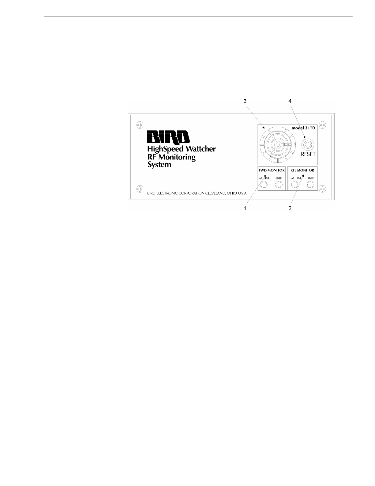
Figure 1-1
Front Panel
1 Forward Monitor
Ac tive LED—In di cates for ward power is be ing mon i tored and an er ror con di tion will be in d i cated
upon fail ure.
Trip LED—In di cates er ror con di tion has oc curred.
2 Reflected Monitor Ac tive LED—In di cates re flected power is be ing mon i tored and an er ror con di tion will be in di -
cated upon fail ure.
Trip LED—In di cates er ror con di tion has oc curred.
3 Audible Alarm If for ward or re flected power set points are ex ceeded an au di ble alarm is sounded. The alarm
works in conjuction with er ror sta tus in di ca tor re flect ing fail ure con di tions.
4 Reset This push but ton re sets the mon i tor ing sys tem to nor mal op er a tion af ter an er ror con di tion has
been cor rected.
Page 12
Bird Se ries 3170A High-Speed Wattcher
RF Mon i toring Sys tem
1-4
Rear Panel
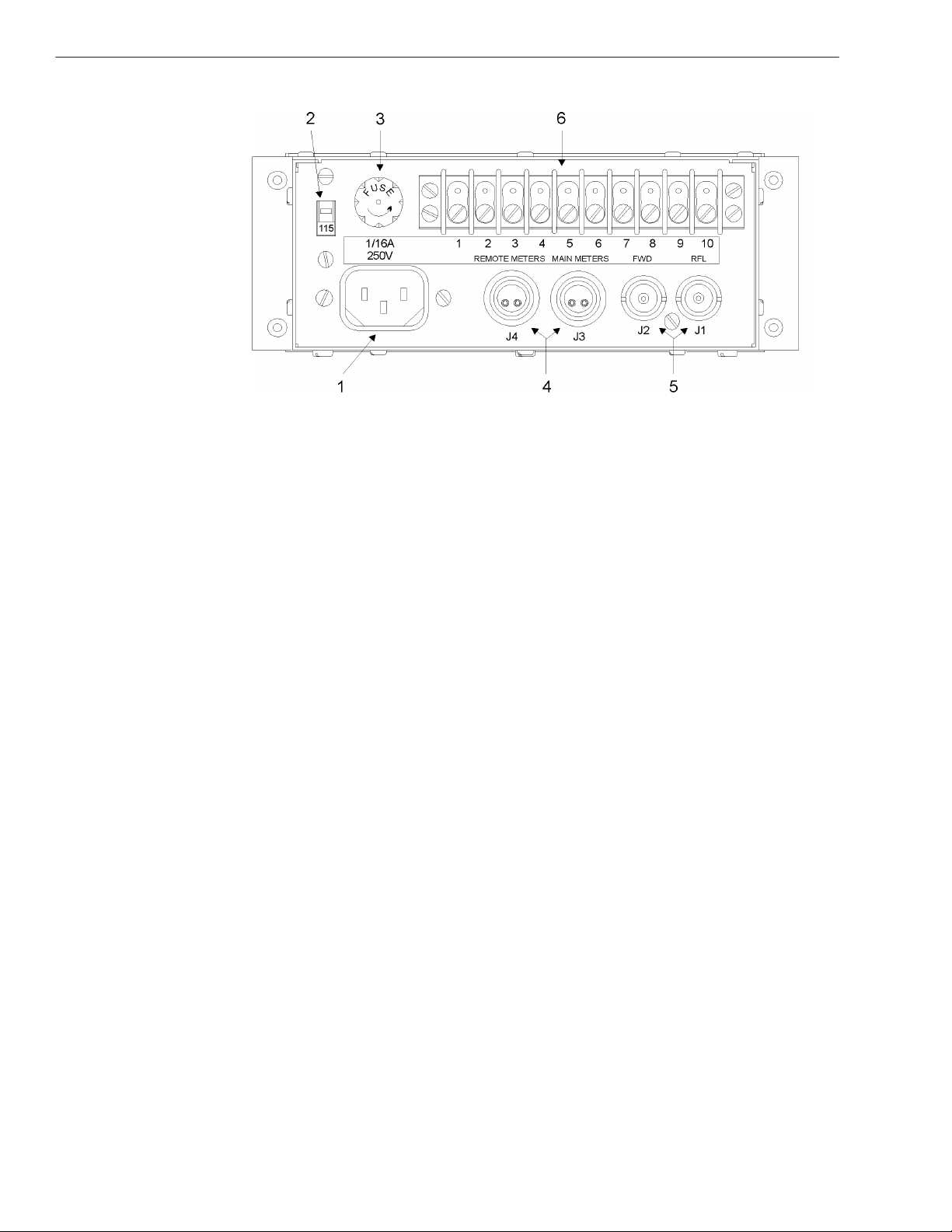
Figure 1-2
Rear Panel
1 AC Receptacle
2 Line Voltage
Selector Switch
3 AC Line Fuse 1/16A at 250V slow-blow fuse, pro vides cir cuit pro tec tion from ex ces sive surge in line power or
Pro vides a means of sup ply ing ac line power to Wattcher con trol unit.
De ter mines line volt age op er a tion.
in the event of com po nent fail ure.
4 Meter
Connections
J3—Con nec tor for front panel main me ters. Can also be used to con nect re mote me ters. Levels:
30 µA full scale into 1400 ohm (42mV).
J4—Ex tra me ter con nec tor for re mote me ters or chart re corder. For de tails on con nect ing r e mote
me ters see Ap pen dix B. Levels: 1.038V full scale. Use 33.2k re sis tor in se ries with stan dard Bird
30 µA me ters.
5 RF Power
Connections
Fe male BNC con nec tors, pro vide means of con nect ing sam pled RF power. J2 is for for ward
power, J1 is for re flected power. Levels: 30 µA full scale into 1400 Ω (42mV). May be over ranged
to 100mV.
6 Terminal Strip A ten con tact ter mi nal strip pro vides con nec tions for var i ous user spe cific ap pli ca tion s. De tails of
con tact as sign ment and ap pli ca tions are in Ap pen dix B.
Page 13
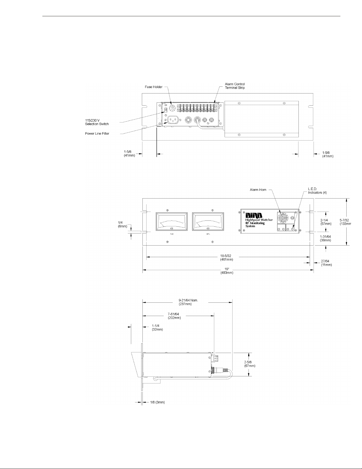
Out line Draw ings
-
1-5
Models 3171A, 3172A,
Figure 1-3
& 3173A
Page 14

Bird Se ries 3170A High-Speed Wattcher
RF Mon i toring Sys tem
1-6
Models 3170A, 3170A200,
Figure 1-4
& 3170A300
Page 15

Chap ter 2
2-1
The ory of Op er a tion
In put Sig nal
Di rect cur rent sig nals rep re sent ing op er at ing power lev els are brought into the RF mon i tor from
the sens ing el e ments through the rear panel jacks J1 and J2. These cur rents are shunted to grou nd
through 1400 ohm re sis tors. The volt age de vel oped across these re sis tors is am pli fied by a pair of
op er a tional am pli fi ers to ap prox i mately one volt (me ter full scale).
The drive cur rent to the main in di cat ing me ters is taken from the am pli fier out puts through se ries
re sis tors of 33.2k ohm each. The drive volt age for re mote me ters also co mes from the am pli f ier
out puts and is buf fered by a pair of op-amps con fig ured for unity gain. This pro tects the
3170A/71A cir cuitry against ac ci den tal short ing of the re mote me ter line.
Ad just ment
The cal i brate/op er ate switch and the two ref er ence po ten ti om e ter al low the user to sub sti tute an
ad just able cur rent in place of the sig nals from the sens ing el e ments to fa cil i tate ad jus t ment of the
set-points.
The three set-point po ten ti om e ter (for ward, re flected, and con firm) pro vide dc volt ages w hich are
com pared to the am pli fier out puts by three com para tors.
The LED to the left of each po ten ti om e ter in di cates whether the in com ing sig nal is higher (LED
ON) or lower (LED OFF) than the set-point of the po ten ti om e ter.
Page 16

Bird Se ries 3170A High-Speed Wattcher
RF Mon i toring Sys tem
2-2
Op er a tions
The out put of the con firm com para tor goes di rectly to the con firm out put drive tran sis tors . The
out put of the re flected com para tor goes di rectly to the alarm cir cuitry and to the re flec to r mon i tor
trip ped LED latch. The out put of the for ward com para tor is gated by the ac ti vate for ward mo n i tor
sig nal AFM be fore go ing to the alarm cir cuitry and LED latch.
In other words, the sig nal is blocked if the ac ti vate for ward mon i tor sig nal is not pres ent . The
AFM sig nal passes through a de lay cir cuit be fore reach ing the gate. The pur pose of the de lay is to
al low for any de lays in the user’s equip ment be tween the ini tial ex ci ta tion of the car rier ON sig nal
and the pres ence of power on the trans mis sion line.
Re set
The re set sig nal clears the horn latch and the two trip LED latches. This sig nal can come from
three sources: the pushbutton switch on the front panel, the rear panel in put/out put, or from the
power-up re set ca pac i tor when the de vice is first turned on or af ter a power in ter rup tion.
Page 17

Chap ter 3
3-1
Prep a ra tion for Use
Gen eral
The se ries 3170A High-Speed Wattcher RF Mon i toring Sys tem was de signed for in door use. This
sec tion con tains in for ma tion on un pack ing and in spec tion; and pre par ing the Wattcher Unit for
use.
Un packing and In spec tion
1. Care fully in spect ship ping con tainer for signs of dam age. If dam age
is no ticed, do not un pack the unit. Immediatly no tify the ship ping
car rier and Bird Elec tronic Cor po ra tion.
2. If con tainer is not dam aged, un pack the unit. Save ship ping ma te ri als for re pack ag ing.
3. In spect unit for vi sual signs of dam age. Immediatly no tify the ship ping car rier and Bird Elec tronic Cor po ra tion of equip ment dam age.
In stal la tion
Mounting The Model 3170A Se ries High Speed Wattcher Sys tem is in tended for rack panel mount ing. The
pan els are de signed to fit ASA stan dard 19 inch size “C” racks.
The Models 3170A, 3170A200 and 3170A300 are fully self-contained units with the RF line sec -
tion mounted on the panel. The Models 3171A, 3171A020, 3172A, and 3173A, how ever, uti lize
re motely mounted line sec tions.
CAU TION
Be sure the 115/230 volt age se lec tor switch on the rear panel is set to the proper line volt -
age be fore ac power is ap plied.
For in stal la tion of Models 3170A, 3170A200, and 3170A300 re fer to fig ure 1-4 Out line Draw ing .
For in stal la tion of Models 3171A, 3171A020, 3172A, and 3173A, re fer to fig ure 1-3 Out line
Draw ing.
Models 3170A,
3170A200, and
3170A300
1. If the back of the unit is not ac ces si ble from the rear of the rack
mount, any con nec tions to the unit must be made be fore the panel is
se cured in place.
2. Con nect the RF co ax ial line to the line sec tion.
3. Make sure the 115/230 line volt age switch is in the proper po si tion
for the volt age sup plied.
Page 18

Bird Se ries 3170A High-Speed Wattcher
RF Mon i toring Sys tem
3-2
4. Con nect the ac power cord from the Wattcher unit to an ap pro pri ate
source. Make dc power con nec tions if needed.
5. Se cure the panel to the rack with ap pro pri ate fas ten ers.
Models 3171A,
3171A020, 3172A,
and 3173A.
1. In sert the line sec tion in the co ax ial RF trans mis sion line. Con nect
the dc ca ble to the line sec tion and run the dc ca ble to the rack con sole unit.
2. If the back of the unit is not ac ces si ble from the rear of the rack
mount, all con nec tions to the unit must be made be fore the panel is
se cured in place.
3. Make sure that the 115/230 line volt age switch is in the cor rect po si tion for the volt age sup plied.
4. Con nect the ac power cord from the Wattcher unit to an ap pro pri ate
source. Make dc power con nec tions if needed.
5. Se cure the panel to the rack mount us ing ap pro pri ate fas ten ers.
Ini tial Setup
WARNING
Do not use electricically conductive tools for calibration when the front panel is removed.
Damage to the unit and or the possibility of electrical shock exists.
When ei ther ac or dc power is ap plied to the unit, the yel low re flected mon i tor ac tive LED s hould
light. If this light does not come on, dis con nect the power cord and re fer to Chap ter 5, Main t e nance. With the yel low re flected mon i tor ac tive LED lit, sig ni fy ing power is ON and the uni t is
op er a tional, pro ceed with the ini tial set up be low.
Preparation 1. Re move the face plate by re mov ing the four screws found in the
cor ners of the face plate. This ex poses the cir cuit board on which
the cal i bra tion con trols are lo cated.
Face Plate Re moval
Figure 3-1
Page 19

2. Set the CAL I BRATE/OP ER ATE switch to the cal i brate po si tion (to
-
3-3
the left).
Con trols and In di ca tors
Figure 3-2
1. Cal i brate/Op er ate Switch
2. For ward Ref er ence Ad just ment Po ten ti om e ter
3. Re flected Ref er ence Ad just ment Po ten ti om e ter
4. For ward Set Point Po ten ti om e ter
5. Re flected Set Point Po ten ti om e ter
6. Con firm Set Point Po ten ti om e ter
7. For ward Mon i tor Ac tive De lay Dip Switch
Adjust Set-points 1. Using the for ward ref er ence po ten ti om e ter ad just the for ward me ter
to in di cate the power level at which the for ward alarm is to be trip ped.
2. Ad just the for ward set-point po ten ti om e ter un til the min ia ture LED
to the left of the po ten ti om e ter is just at the tran si tion from off to
on.
+ NOTE: Turn ing the po ten ti om e ter clock wise will raise the set-point and turn the light off.
3. Using the re flected ref er ence po ten ti om e ter and the re flected
set-point po ten ti om e ter, set the re flected trip point in a sim i lar man ner. The alarm will trip dur ing this op er a tion un less the RE SET but ton is held in.
4. The con firm set-point is ad justed us ing the for ward ref er ence po ten ti om e ter and the con firm set-point po ten ti om e ter. If the con firm out put is not used, it is not nec es sary to ad just the con firm set-point
po ten ti om e ter.
5. Once the set-points are ad justed, the CAL I BRATE/OP ER ATE
switch can be re turned to the op er ate po si tion (to the right). If us ing
ac tive for ward mon i tor ca pa bil ity then pro ceed to para graph 3-6. If
not, then re place the face plate.
Page 20

Bird Se ries 3170A High-Speed Wattcher
RF Mon i toring Sys tem
3-4
Active Forward
Monitor Setup
In ter nal cir cuitry sets Ac tive For ward Mon i tor ( AFM ) in put to a high state. This in hib its mon i tor ing of for ward power on trans mis sion line. To mon i tor for ward power, fol low the steps be low .
1. Con nect AFM in put to ground by hardwiring ter mi nal strip po si tion
10 ( AFM in put) to po si tion 7 (ground).
2. Se lect the ap pro pri ate de lay (see ta ble 3-1). This de lay al lows trans mit ting equip ment to reach ac cept able power out put be fore be ing
mon i tored by for ward chan nel for low power con di tion.
There are two ways to de ter mine the re quired de lay:
a. If the de lay in the user’s equip ment is known, the AFM should be
set to the same de lay plus a min i mum of 25 per cent safety fac tor.
b. The sec ond al ter na tive is to set the AFM to pro gres sively shorter
de lays un til switch ing on the car rier causes the FWD mon i tor to trip
when the user’s equip ment is known to be work ing prop erly. Then
add a 25 per cent safety fac tor to the de lay in di cated by the switch
set ting and set the de lay to that set ting.
+ NOTE: that the dis abling of the for ward mon i tor is vir tu ally in stan ta neous when the AFM sig -
nal is re moved and is un af fected by the switch set tings.
Dip Switch Settings Dip Switch bank S02 is used to se lect AFM de lay time. Re fer to fig ure 3-3 for cor rect on / off po -
si tion. Be sure the switches or set fully on or off.
Figure 3-3
S02 Dip Switch
Table 3-1
Set ting AFM De lay
In ta ble 3-1 the de lay times are listed in the ap pro pri ate row & col umn for the switch set ti ngs.
+ NOTE: The de lay times are dif fer ent for the model 3170A300.
SW6 ON
SW5 OFF
SW4 OFF
SW1 SW2 SW3 3170A300 All Other
Models
ON ON ON 7.1ms
OFF ON ON 8.3ms
71 µs
83 µs
SW6 OFF
SW5 ON
SW4 OFF
3170A300 All Other Models 3170A300 All Other Models
71ms
710 µs
710m
SW6 OFF
SW5 OFF
SW4 ON
7.1s
s
83ms
830 µs
830m
8.3s
s
ON OFF ON 10.0ms
OFF OFF ON 12.1ms
100 µs
121 µs
100m
s
121m
s
1ms 1s 10.0s
1.21ms 1.21s 12.1s
Page 21

Remote Meter Cable
-
3-5
Assembly
Re mote me ters can be con nected to J4. The fol low ing in struc tions are pro vided for as sem bl ing ca bles for re mote me ter mount ing.
Ca ble rec om mended is Belden num ber 8208, 18 AWG braided shield wire. Bird p/n is 5-704. Re quired con nec tor plug is Bird p/n 5-665.
Re mote Me ter Ca ble
Figure 3-4
1. Cut ca ble to de sired length.
2. Strip and tin wires to lengths as shown.
3. Dis as sem ble con nec tor and as sem ble the plug sec tion on the ca ble.
In sert wires into pins mak ing sure the red wire is in serted in to pin
num ber two and the white wire to pin one. Soft sol der these con nec tions se curely.
4. In sert the shield braid ing be tween the spring coils and clip short.
Re as sem ble the con nec tor’s outer con duc tor and tighten the set
screws se curely.
5. Ser vice the other end of the ca ble as shown. Con nect two black
leads to the braided ground wire as shown. The red wire is the for ward power and the white is the re flected power.
Page 22

Bird Se ries 3170A High-Speed Wattcher
RF Mon i toring Sys tem
3-6
Page 23

Chap ter 4
4-1
Op er ating In struc tions
Gen eral
When the unit is in stalled and con nected to a trans mit ter for re mote mon i tor ing, me ter ing , or ex ter nal alarms and func tions as your in stal la tion re quires, op er a tor at ten tion is not re quired. The
equip ment will com pletely mon i tor a trans mit ter’s op er a tion. The only time op er at ing pe r son nel
will be nec es sary is to re set the unit if it has not been wired for au to matic or re mote re se t. Re fer to
Ap pen dix B for dif fer ent ap pli ca tions in which the Wattcher mon i tor can be used.
RF Power Mea sure ment
RF power mea sure ments are made by the in ser tion of the de tec tor el e ments into the line sec tion.
The el e ments are se lected for the fre quency range and power level used.
For ward and re flected power is in di cated when the ar row on the el e ment plate points in the d i rec tion of power flow. The for ward power flows from the trans mit ter to the load or an tenna and the
re flected power flows from the load or an tenna to the trans mit ter.
When the de tect ing el e ment is placed in the line sec tion, be sure it is fully seated and fully ro tated
to the stop for the ap pro pri ate in di cat ing po si tion. Also be sure the el e ment catch on th e el e ment
socket face of the line sec tion is in place on the shoul der of the el e ment. This will as sure g ood
con tact be tween the el e ment and line sec tion body.
El e ments are se lected for the power and fre quency range re quired. Since the re flected power i s
gen er ally much less than the for ward power, it may be ben e fi cial to se lect an el e ment of l ower
power value for the re flected side. This will al low better read ing res o lu tion. Gen erally el e ments of
a ten to one ra tio are used.
Page 24

Bird Se ries 3170A High-Speed Wattcher
RF Mon i toring Sys tem
4-2
Page 25

Chap ter 5
5-1
Main te nance
With ba sic care, the se ries 3170A should pro vide many years of trou ble free op er a tion. This sec tion con tains op er a tor main te nance in struc tions. Any main te nance or ser vice pro ce dure be yond the
scope of those pro vided in this sec tion should be re ferred to a qual i fied ser vice cen ter.
Sales / Repair
Facilities
U.S.A. Sales and Man u fac turing
Ser vice Group
Bird Elec tronic Cor po ra tion
30303 Au rora Road
Cleve land (Solon), Ohio 44139-2794
Phone: (440)248-1200 Ca ble: BIRDELEC
Fax: (440)248-5426 Telex: 706898 Bird Elec UD
Sales Facilities For the lo ca tion of Sales Of fice near est you, give us a call or visit our Web site at:
http :// www .bird-electronic.com
Safety Considerations When ser vic ing the se ries 3170A or re lated elec tri cal equip ment, ob serve the fol low ing sa fety pre -
cau tions:
WARNING
Become thoroughly familiar with modern methods of resuscitation before working near high
voltage sources.
WARNING
Shock hazard. Always turn off AC power before removing any equipment panels.
Page 26

Bird Se ries 3170A High-Speed
RF Mon i toring Sys tem
5-2
Cleaning
Front Panel Clean the front panel face and me ters with a soft cloth damp ened with a mild de ter gent so lu ti on.
Connectors Clean the line sec tion con nec tors and el e ments with a dry clean ing sol vent. Use a clean clot h to
Pre ven tive Main te nance
Pre ven tive main te nance is lim ited to clean ing the unit and con nec tors.
WARNING
Disconnect this unit from ac power source before any disassembly for cleaning, repair or
replacement procedures. The potential for electrical shock exists.
WARNING
When using dry cleaning solvents, provide adequate ventilation and observe normal safety
precautions. Many dry cleaning agents emit toxic fumes that may be harmful to your health
if inhaled.
Do not use an ex ces sive amount of wa ter that would en ter the unit and dam age elec tri cal com po nents.
clean the mat ing sur faces of the larger line sec tions and a cot ton swab stick for the smaller c on nec tors, el e ments, and line sec tion el e ment socket. Clean all mat ing sur faces thor oughly, es p e cially
the bot tom shoul der of the el e ment socket and the spring con tact fin ger. Do not bend this con tact
fin ger when clean ing. The po si tion of this con tact is some what crit i cal. If it is out too f ar the el e ment will not en ter the socket and if it is in too far, it will not make con tact with the but ton on the
el e ment.
Page 27

-
5-3
Table 5-1
Trou ble shooting
Ta ble 5-1 con tains trou ble shoot ing in for ma tion for prob lems which can oc cur dur ing nor m al op er a tion. Lo cate the prob lem, re view the pos si ble cause, and per form the cor rec tive ac tion
listed.
Only those func tions within the scope of nor mal main te nance are listed. This man ual can not li st
all mal func tions that may oc cur, or cor rec tive ac tions. If a mal func tion is not listed or n ot cor rected by the listed cor rec tive ac tions, no tify a qual i fied ser vice cen ter.
Page 28

Bird Se ries 3170A High-Speed
RF Mon i toring Sys tem
5-4
Dis as sem bly
Meter Replacement If the me ters should be come de fec tive and re quire re place ment, pro ceed as out lined in the fol low -
ing steps:
1. Re move the hous ing that cov ers the back of the me ters by un screw ing the four 4-40 oval head screws from the front panel. These
screws are lo cated above and be low the me ter faces. The cover will
come right off.
2. Ob serve the con nec tions of the me ter leads, to main tain the cor rect
po lar ity in re as sem bly. Then dis con nect the leads.
3. Loosen the clamp screw on the sides of the me ter un til the clamp is
re leased and can be taken off. The me ter may now be with drawn
for ward through the front panel.
4. The me ters are re placed by merely re vers ing the above pro ce dures.
Replace DC Fuse
WARNING
Disconnect this unit from ac power source before any disassembly for cleaning, repair or
replacement procedures. The potential for electrical shock exists.
1. Re move top cover.
2. Using a fuse puller or a small flat blade screw driver, care fully re move the fuse from fuse clips.
+ NOTE: The fuse is lo cated on the cir cuit board, to ward the back right cor ner.
3. Re place with same type and rat ing fuse. 3 AG,
5-721-2
4. Re place top cover.
Stor age
If the unit is not to be used for an ex tended pe riod of time, store in a cool dry place where it will
be free from rough treat ment, dust, and damp ness.
Re pack aging
1
Amp Bird P/N
2
Should you need to re turn the Wattcher unit, use the orig i nal ship ping pack age if pos si ble. If the
orig i nal pack age is not avail able, use a heavy duty cor ru gated box with shock-absorbing ma te rial
around all sides of the unit to pro vide firm cush ion and to pre vent move ment in con tainer. Con tainer should be prop erly sealed.
Page 29

Re place ment Parts List
-
5-5
QTY . DE SCRIP TION PART NUMBER
1 AC power fuse -3 AG, 1/16 A 5-721-15
1 DC power fuse -3 AG, 1/2 A 5-721-2
1 Power cord, 115/230 Vac 4421-055
2 Ca ble as sem bly 3170-058-1
1 Me ter ca ble as sem bly 3170-057
2 Me ter
Models 3170A, 3170A200,
3170A300, 3172A, & 3173A 2150-015
Model 3171A 2150-086
Model 3171A020 2150-093
1 Line sec tion as sem bly
(Model 3170A only) 4522- 002
DC Ca ble As sem blies
Length Part Num ber Length Part Num ber
14" 3170-058-1 6’ 3170-058-6
15’ 3170-058-2 25’ 3170-058-3
1
25’
50’ 3170-058-5 80’ 3170-058-7
90’ 3170-058-8 100’ 3170-058-9
1
Use if line sec tion is
3171-010 40 3170-058-4
1
"
6
8
Table 5-2
El e ment Ta bles
The fol low ing ta bles are used to de ter mine the part num bers of el e ments re quired based on line
sec tion, power, and fre quency ranges.
Ta ble 5-2 should be used to de ter mine which el e ment ta ble to use, based on the model.
Ta bles 5-3 through 5-15 are num bered con sec u tively for con ve nience. The ta ble head ing cor re -
sponds to the ta ble head ing in the Bird cat a log which is the com mon ref er ence for el e ment ta bles.
Trou ble shooting
Model Line Sec tion
Mount
Front
Panel
3170A 4 4 3 - 8
3170A200 4 4 3 - 8
3170A300 4 4 3 - 8
3171A 4 4 9 11 14
Ex ter nal
Me ter Scale Line Sec tion in Inches
Watts ki lo Watts
25/50/1005/10/2515/30/6
0
7
8
1
Ta ble (5-)
5
8
1
3
8
1
6
8
Page 30

Bird Se ries 3170A High-Speed
RF Mon i toring Sys tem
5-6
7
" Line Section The fol low ing ta bles are used to se lect el e ments for
8
Table 5-3
Model Line Sec tion
Me ter Scale Line Sec tion in Inches
Mount
Front
Panel
3170A 4 4 3 - 8
3170A200 4 4 3 - 8
3170A300 4 4 3 - 8
3171A 4 4 9 11 14
3171A020 4 4 10 13 15
3172A 4 4 3 - 8
3173A 4 4 3 - 8
Table 5-4
Power
Range
Ex ter nal
Watts ki lo Watts
25/50/1005/10/2515/30/6
Fre quency (MHz)
2-30 25-60 50-125 100-250 200-500 400-1000
(Watts)
5 — 5A 5B 5C 5D 5E
10 — 10A 10B 10C 10D 10E
25 — 25A 25B 25C 25D 25E
50 50H 50A 50B 50C 50D 50E
100 100H 100A 100B 100C 100D 100E
250 250H 250A 250B 250C 250D 250E
500 500H 500A 500B 500C 500D 500E
1000 1000H 1000A 1000B 1000C 1000D 1000E
2500 2500H
5000 5000H
7
" line sec tions.
8
0
7
8
Trou ble shooting
5
1
3
8
Ta ble (5-)
Se lec tion Ta ble
1
1
6
8
8
Stan dard El e ments
Page 31

-
5-7
Table 5-5
Table 5-6
Power Range
(Watts)
High Fre quency Milliwatt El e ments
Fre quency Band
.45 to 2.5 MHz
En tire Ta ble 8% FS
1000 1000P
2500 2500P
5000 5000P
10000 10000P
Low Fre quency El e ments
Low Power El e ments
Power
Range
(milliwa
905-12601250-1
500
Fre quency Bands (MHz)
1500-1
700
1700-2
200
2200-2
300
2300-2
400
2400-2
500
tts )
100 430-82430-209430-210430-178430-41 430-211430-182430-90
2500-2
600
Table 5-7
Low Power El e ments
Power
Range
(milliwa
905-12601250-1
500
Fre quency Bands (MHz)
1500-1
700
1700-2
200
2200-2
300
2300-2
400
2400-2
500
2500-2
600
tts )
Page 32

Bird Se ries 3170A High-Speed
RF Mon i toring Sys tem
5-8
Table 5-8
100 mW
Fre quency
Band (MHz)
Cat. No 250 mW
Fre quency
Band (MHz)
Cat. No. 500 mW
Fre quency
Band
45-50 430-266 45-50 430-267 45-54 430-242
50-60 430-191 50-60 430-212 54-60 430-243
60-66 430-192 60-66 430-213 60-66 430-244
66-72 430-193 66-72 430-214 66-72 430-245
72-76 430-2 72-76 430-22 72-76 430-33
76-82 430-194 76-82 430-215 76-88 430-246
82-88 430-195 82-88 430-216 88-108 430-247
88-97 430-170 88-108 430-217 105-120 430-26
97-108 430-171 105-120 430-20 120-136 430-248
108-136 430-57 116-126 430-48 136-150 430-249
135-175 430-86 125-136 430-218 150-170 430-53
170-190 430-62 130-150 430-13 170-190 430-250
190-210 430-63 150-180 430-15 190-216 430-251
210-216 430-176 170-190 430-64 216-240 430-252
216-230 430-196 190-210 430-65 240-290 430-27
230-240 430-197 210-220 430-184 290-340 430-253
240-250 430-198 216-230 430-219 340-360 430-157
250-260 430-199 230-240 430-220 350-400 430-254
260-270 430-200 240-250 430-221 400-450 430-255
270-280 430-201 250-260 430-222 450-500 430-256
280-290 430-202 260-270 430-223 500-600 430-257
290-300 430-203 270-280 430-224 600-800 430-258
300-320 430-204 280-290 430-225 800-1000 430-265
320-340 430-205 290-300 430-226
340-360 430-164 300 -320 430-227
360-380 430-206 320-340 430-228
380-400 430-207 340-360 430-229
400-420 430-7 360-380 430-230
420-450 430-208 375-400 430-231
450-470 430-8 400-450 430-232
470-500 430-179 450-470 430-61
500-600 430-168 470-500 430-233
600-800 430-169 500-600 430-234
800-1000 430-263 600-800 430-235
800-1000 430-264
Cat. No.
Page 33

5
-
5-9
1
" Line Section The fol low ing ta bles are used to se lect el e ments for 1
8
Table 5-9
5
" line sec tions.
8
Low Fre quency El e ments
Table 5-10
Power
Range
(Watts)
950-12601100-1
800
1700-2
200
Fre quency (MHz)
2200-2
2300-24002400-25002500-26002600-27
300
1 1 J 1 K 1 L 1 M 431-17 431-20 431-23 431-12
2.5 2.5 J 2.5 K 2.5 L 2.5 M 431-110431-107431-10
8
5 5 J 5 K 5 L 5 M 432-15 432-28 432-2 432-12
High Fre quency El e ments
En tire Ta ble 8% FS
Milliwatt El e ments
Power
Range
2-30 25-60 50-125 100-250 200-500 400-1000
Fre quency Bands (MHz)
100 W — 100A12 100B12 100C12 100D12 100E12
250 W — 250A12 250B12 250C12 250D12 250E12
500 W 500H12 500A12 500B12 500C12 500D12 500E12
00
0
431-11
7
1
3
" Line Section The fol low ing ta bles are used to se lect el e ments for 3
8
Table 5-11
Power
Range
2-30 50-125 100-250 400-1000
Fre quency Bands (MHz)
(Watts)
300 300H12 300B12 300C12 300E12
600 600H12 600B12 600C12 600E12
1500 1500H12 1500B12 1500C12 1500E12
3000 3000H12 3000B12 3000C12 3000E12
6000 6000H12 6000B12 6000C12 6000E12
15k 15KH12 15KB12
1
" line sec tions.
8
5
1-
5
1-
AA Stan dard El e ments 30 µA
8
BB Stan dard El e ments 30 µA
8
Page 34

Bird Se ries 3170A High-Speed
RF Mon i toring Sys tem
5-10
Table 5-12
Table 5-13
1
6
" Line Section
8
Table 5-14
5
1-
BB Stan dard El e ments 30 µA
8
Power
Range
2-30 25-60 50-125 100-250 200-500 400-1000
Fre quency Bands (MHz)
100 W — 100A32 100B32 100C32 100D32 100E32
1
AA Stan dard El e ments 30 µA
3
8
Power Range
50kW
30 µA
25-60 50-125 100-250
50KA42 50KB42 50KC42
The fol low ing ta bles are used to se lect el e ments for 6
Power
Range
Fre quency Bands (MHz)
50-125 100-250 400-100
Fre quency bands (MHz)
1
" line sec tions.
8
0
600 W 600B32 600C32 600E32
1500 W 1500B321500C321500E3
2
3000 W 3000B323000C323000E3
2
6000 W 6000B326000C326000E3
2
15 kW 15KB32 15KC32 15KE32
1
3
AAA
8
1
3
AAA
8
Table 5-15
1
BB
3
8
Power
Range
2-30 25-60 50-125 100-250 200-500 400-1000
Fre quency Bands (MHz)
250 W — 250A62 250B62 250C62 250D62 250E62
500 W — 500A62 500B62 500C62 500D62 500E62
1000 W 1000H62 1000A62 1000B62 1000C62 1000D62 1000E62
2500 W 2500H62 2500A62 2500B62 2500C62 2500D62 2500E62
5000 W 5000H62 5000A62 5000B62 5000C62 5000D62 5000E62
10 kW 10KH62 10KA62 10KB62 10KC62 10KD62 10KE62
25 kW 25KH62 25KA62 25KB62 25KC62 25KD62 25KE62
50 kW 50KH62 50KA62 50KB62 50KC62 50KD62 50KE62
Page 35

Dif fer ence Data Sheet
A-1
Ta ble A-1 is used to out line the dif fer ences be tween var i ous mod els.
Table A-1
Dif fer ences
Be tween Models
Model Line Sec tion
Mount
Me ter Scale AFM De lay
Ad just ment
AFM: Off State
Levels
Range
Front
Panel
3170A 4 4 4 4
3170A200 4 4 4 4
3170A300 4 4 4 4
3171A 4 4 4 4
3171A020 4 4 4 4
3172A 4 4 4 4
3173A 4 4 4 4
Ex ter nal
Watts ki lo Watts 70ms to
25/50/1005/10/2515/30/6
50ms
0
7.1ms
to 5s
Hold to
+5V
In ternally
+2.4 to
+5V
Page 36

Bird Se ries 3170A High-Speed Wattcher
RF Mon i toring Sys tem
A-2
Page 37

Ap pen dix B
B-1
User Ap pli ca tions and Wiring
This sec tion is a col lec tion of user spe cific ap pli ca tions and the wir ing in for ma tion re quired to ac ti vate them.
Con nec tor As sign ment
Con nec tion De scrip tion Func tion Levels
BNC Jacks
J1 & J2
J3 DC Main Me ter
J4 DC Re mote
TB1,2 Ex ter nal 12V
TB3,4 Aux il iary Alarm
TB5 5V Out put Reg u lated 5V out put Can sup ply 360mA
TB6 Alarm Out put Low when alarm is
TB7 Ground Chas sis ground Ref er ence for sig nals.
TB8 Re set In put /
TB9 Con firm Out put Low when for ward
DC In put
For ward &
Re flected
Drive Out put
Me ter Drive
Out put
Sup ply
In puts
Out put
De tected RF sig nals
from sen sors
Cur rent to drive
in di cat ing me ters
Volt age to drive re mote
in di cat ing me ters
Used to al low mo bile
op er a tion
Sig nals to trip alarms
from ex ter nal sources
sound ing, re turned
high by re set
In put to re set Wattcher
from ex ter nal source.
May be used as an
out put to re set other
equip ment when
Wattcher is re set by
the front panel switch.
power ex ceeds the
us ers con firm set point
30 µA full scale into
1400 Ω (42mV). May
be overranged to
100mV
30 µA full scale into
1400 Ω (42mV)
1.038V full scale (use
33.2k re sis tor in se ries
with stan dard Bird
30 µA me ters
See page B-5 for con nec tion in for ma tion
TTL lev els, ac tive low.
Pulled up to 5V by
4.7k in ter nally.
Shunted to ground by
0.1 µF ca pac i tor.
max.
TTL lev els, ac tive low.
Open col lec tor pulled
up to 5V by 4.7k. Will
sink 180mA.
TTL lev els, ac tive low.
Pulled up to 5V by
4.7k in ter nally.
Shunted to ground by
10 µF ca pac i tor.
TTL lev els, ac tive low.
Open col lec tor pulled
up to 5V by 4.7k. Will
sink 180mA.
Page 38

Bird Se ries 3170A High-Speed Wattcher
RF Mon i toring Sys tem
B-2
Ac tive For ward Mon i tor (AFM) In put
Wiring con cept ex am ples for ac ti vat ing the AFM cir cuit are shown be low. These can be used f or
re mote on site or off site man ual or au to matic ac ti va tion.
Dry Contact Closure Clo sure will be from ter mi nal 10 to case ground, ter mi nal 7, in any con ve nient form, e.g. by an ex -
tra set of man ual con tacts on the trans mit ter key ing re lay or a sep a rate re mote switch .
Dry Con tact Clo sure
Figure B-1
Logic “1" Closure
Figure B-2
Logic “1" Clo sure
Clo sure cir cuit shown is a sim pli fied means of in ter fac ing a logic “1" as re quired from TTL driv ing pos i tive sig nal, in di cat ing trans mit ter is on .
Page 39

Con firm Out put
-
B-3
For vi sual con fir ma tion of trans mit ter “ON” see cir cuit be low.
Relay Control Re lay con trol for greater cur rent re quire ments .
Figure B-3
Con firm Out put
Re lay Con trol
LED Indicator
Figure B-4
Con firm Out put
LED In di ca tor
Sim ple lo cal or re mote light emit ting di ode in di ca tor, that re quires no more than 180mA .
Page 40

Bird Se ries 3170A High-Speed Wattcher
RF Mon i toring Sys tem
B-4
Re set In put
A re mote re set could be used in case of false alarm or a brief dis tur bance has trip ped the Wat tcher
Mon i tor but left the trans mis sion in tact.
Remote Contact Reset This op tion al lows re set on site, but re mote from the Wattcher unit. Ter mi nal 8, Re set, is a c tive
low and will cause a re set when the switch is closed, mak ing a con nec tion to ter mi nal 7, grou nd.
One or sev eral mo men tary con tact, nor mally open, switches can be con nected in se ries for re set
from var i ous lo ca tion s.
Figure B-5
Re set In put
Figure B-6
Ex ter nal Alarms
Ex ter nal Alarms
Var i ous sen sors or sys tems may be con nected to the ex ter nal alarm, ter mi nals 3 or 4. Ter m i nals 3
and 4 are ac tive low in puts. An alarm con di tion oc curs when ei ther ter mi nal is pulled low. Un der
nor mal op er at ing con di tions, these in puts are held high by in ter nal re sis tor s.
Re mote Mon i toring or Me tering
Page 41

-
B-5
Figure B-7
Re mote Mon i tors
and Me ters
Re mote mon i tor ing is ac com plished by con nect ing a re corder to the re mote me ter jack, J4. An
X-Y re corder can be used for time log ging of for ward and re flected power per FCC re quire ments
for re mote sites.
Any num ber of me ter pairs can be driven by the me ter am pli fi ers up to 1mA into a to tal load of
470 to 1400 ohms, with out ef fect ing scale shape. Long line losses are com pen sated by ad just i ng
am pli fier gain and full scale me ter cur rent af ter net work is bal anced and am pli fier zero s et ting.
Usually RFI pre ven tion by shield ing, us ing chokes and by-pass ca pac i tors, is nec es sary onl y near
the Wattcher unit.
Figure B-8
DC Power Sup ply
DC Power Sup ply Con nec tions
A dc power sup ply can be con nected to al low for mo bile op er a tion of the Wattcher unit.
The pos i tive ter mi nal of the dc power sup ply must be con nected to Ter mi nal 1. The neg a tiv e ter -
mi nal must be con nected to ter mi nal 2. The min i mum dc volt age re quired for op er a tion is
+12.7Vdc. The max i mum dc volt age al low able is +16Vdc. The max i mum cur rent draw for this
range is 400mA .
Page 42

Bird Se ries 3170A High-Speed Wattcher
RF Mon i toring Sys tem
B-6
 Loading...