

Page 1

Transmitter Power Monitor/Meter
Operations Manual
Model TPM series
&
3140A Power Meter Panel
The information within this manual is as complete as possible at the time of
printing. Bird Electronic Corporation is not liable for errors. Specifications,
limits, and text are subject to change without notice.
©Copyright 2008 by Bird Electronic Corporation
Instruction Book Part Number 920-TPM Rev. B
Microsoft and Windows are registered trademarks
of the Microsoft Corporation
Page 2

Safety Precautions
The following are general safety precautions that are not necessarily
related to any specific part or procedure, and do not necessarily appear
elsewhere in this publication. These precautions must be thoroughly
understood and apply to all phases of operation and maintenance.
WARNING
Keep Away From Live Circuits
Operating Personnel must at all times observe general safety
precautions. Do not replace components or make adjustments to the
inside of the test equipment with the high voltage supply turned on.
To avoid casualties, always remove power.
WARNING
Shock Hazard
Do not attempt to remove the RF transmission line while RF power
is present.
WARNING
Do Not Service Or Adjust Alone
Under no circumstances should any person reach into an enclosure
for the purpose of service or adjustment of equipment except in the
presence of someone who is capable of rendering aid.
WARNING
Safety Earth Ground
An uniterruptible earth safety ground must be supplied from the
main power source to test instruments. Grounding one conductor of
a two conductor power cable is not sufficient protection. Serious
injury or death can occur if this grounding is not properly supplied.
WARNING
Resuscitation
Personnel working with or near high voltages should be familiar
with modern methods of resuscitation.
WARNING
Remove Power
Observe general safety precautions. Do not open the instrument
with the power on.
Page 3

Safety Symbols
WARNING
Warning notes call attention to a procedure, which if not correctly
performed, could result in personal injury.
CAUTION
Caution notes call attention to a procedure, which if not correctly
performed, could result in damage to the instrument.
Note: Calls attention to supplemental information.
Warning Statements
The following safety warnings appear in the text where there is danger to operating and maintenance personnel, and are repeated here
for emphasis.
WARNING
Disconnect the unit from the RF power source and the ac line
before any disassembly. The potential for electrical shock exists.
Refer to page 19.
Caution Statements
The following equipment cautions appear in the text and are repeated
here for emphasis.
CAUTION
Pin 4 must be connected to power supply ground, other grounds can
be left open if desired.
Refer to page 4.
CAUTION
DB9 are not serial connections. Serial connections to them could
damage the equipment.
Refer to page 7.
i
Page 4

CAUTION
A Bird Calibration Kit is recommended for this procedure.
Performing a calibration with anything other than a Bird
Calibration Kit voids Bird’s accuracy guarantee.
Performing a field calibration will void any remaining warranty on
this product. Bird recommends waiting until the terms of the
warranty have passed before performing a field calibration.
Refer to page 9.
CAUTION
Do not use harsh or abrasive detergents for cleaning.
Refer to page 19.
ii
Page 5

Safety Statements
USAGE
ANY USE OF THIS INSTRUMENT IN A MANNER NOT
SPECIFIED BY THE MANUFACTURER MAY IMPAIR THE
INSTRUMENT’S SAFETY PROTECTION.
USO
EL USO DE ESTE INSTRUMENTO DE MANERA NO
ESPECIFICADA POR EL FABRICANTE, PUEDE ANULAR LA
PROTECCIÓN DE SEGURIDAD DEL INSTRUMENTO.
BENUTZUNG
WIRD DAS GERÄT AUF ANDERE WEISE VERWENDET ALS VOM
HERSTELLER BESCHRIEBEN, KANN DIE GERÄTESICHERHEIT
BEEINTRÄCHTIGT WERDEN.
UTILISATION
TOUTE UTILISATION DE CET INSTRUMENT QUI N’EST PAS
EXPLICITEMENT PRÉVUE PAR LE FABRICANT PEUT
ENDOMMAGER LE DISPOSITIF DE PROTECTION DE
L’INSTRUMENT.
IMPIEGO
QUALORA QUESTO STRUMENTO VENISSE UTILIZZATO IN
MODO DIVERSO DA COME SPECIFICATO DAL PRODUTTORE
LA PROZIONE DI SICUREZZA POTREBBE VENIRNE
COMPROMESSA.
iii
Page 6

SERVICE
SERVICING INSTRUCTIONS ARE FOR USE BY SERVICE TRAINED PERSONNEL ONLY. TO AVOID DANGEROUS
ELECTRIC SHOCK, DO NOT PERFORM ANY SERVICING
UNLESS QUALIFIED TO DO SO.
SERVICIO
LAS INSTRUCCIONES DE SERVICIO SON PARA USO
EXCLUSIVO DEL PERSONAL DE SERVICIO CAPACITADO. PARA
EVITAR EL PELIGRO DE DESCARGAS ELÉCTRICAS, NO
REALICE NINGÚN SERVICIO A MENOS QUE ESTÉ
CAPACITADO PARA HACERIO.
WARTUNG
ANWEISUNGEN FÜR DIE WARTUNG DES GERÄTES GELTEN
NUR FÜR GESCHULTES FACHPERSONAL.
ZUR VERMEIDUNG GEFÄHRLICHE, ELEKTRISCHE SCHOCKS,
SIND WARTUNGSARBEITEN AUSSCHLIEßLICH VON
QUALIFIZIERTEM SERVICEPERSONAL DURCHZUFÜHREN.
ENTRENTIEN
L’EMPLOI DES INSTRUCTIONS D’ENTRETIEN DOIT ÊTRE
RÉSERVÉ AU PERSONNEL FORMÉ AUX OPÉRATIONS
D’ENTRETIEN. POUR PRÉVENIR UN CHOC ÉLECTRIQUE
DANGEREUX, NE PAS EFFECTUER D’ENTRETIEN SI L’ON N’A
PAS ÉTÉ QUALIFIÉ POUR CE FAIRE.
ASSISTENZA TECNICA
LE ISTRUZIONI RELATIVE ALL’ASSISTENZA SONO PREVISTE
ESCLUSIVAMENTE PER IL PERSONALE OPPORTUNAMENTE
ADDESTRATO. PER EVITARE PERICOLOSE SCOSSE
ELETTRICHE NON EFFETTUARRE ALCUNA RIPARAZIONE A
MENO CHE QUALIFICATI A FARLA.
iv
Page 7

RF VOLTAGE MAY BE PRESENT IN RF ELEMENT SOCKET - KEEP
ELEMENT IN SOCKET DURING OPERA TION.
DE LA TENSION H.F. PEAT ÊTRE PRÉSENTE DANS LA PRISE DE
L'ÉLÉMENT H.F. - CONSERVER L'ÉLÉMENT DANS LA PRISE LORS
DE L'EMPLOI.
HF-SPANNUNG KANN IN DER HF-ELEMENT-BUCHSE ANSTEHEN ELEMENT WÄHREND DES BETRIEBS EINGESTÖPSELT LASSEN.
PUEDE HABER VOL TAJE RF EN EL ENCHUFE DEL ELEMENTO RF MANTENGA EL ELEMENTO EN EL ENCHUFE DURANTE LA
OPERACION.
IL PORTAELEMENTO RF PUÒ PRESENTARE VOLTAGGIO RF TENERE L'ELEMENTO NELLA PRESA DURANTE IL
FUNZIONAMENTO.
v
Page 8

About This Manual
This manual covers the operating and maintenance instructions for
the following models:
All TPM series 3140A4 3140A8
Changes to this Manual
We have made every effort to ensure this manual is accurate. If you
discover any errors, or if you have suggestions for improving this man
ual, please send your comments to our Solon, Ohio factory. This manual may be periodically updated. When inquiring about updates to
this manual refer to the part number and revision on the title page.
Terminology
There are some unique terms used throughout this literature. They
are defined here clarify any misunderstanding.
TPM - Refer to the in-line Transmitter Power Monitor.
Display or Panel Meter - Refers to either the 3140A4 or 3140A8 meter.
-
Contents
Chapter Layout
Introduction
as a general overview of the product.
Installing & Operating Instructions - TPM — Describes the features of
the Transmitter Power Monitor and provides power-up instructions.
Installing & Operating Instructions - 3140A Panel — Describes the
features of the Power Meter Panel and provides power-up instructions.
Calibration — Describes different calibration methods and when to
use them.
Performance Specifications — Specifications and parts information
are also listed.
vi
— Describes the purpose and function of the TPM as well
Page 9

Table of Contents
Safety Symbols. . . . . . . . . . . . . . . . . . . . . . . . . . . . . . . . . . . . . . . . . . i
Warning Statements . . . . . . . . . . . . . . . . . . . . . . . . . . . . . . . . . . . . . i
Caution Statements. . . . . . . . . . . . . . . . . . . . . . . . . . . . . . . . . . . . . . i
Safety Statements . . . . . . . . . . . . . . . . . . . . . . . . . . . . . . . . . . . . . . iii
Changes to this Manual . . . . . . . . . . . . . . . . . . . . . . . . . . . . . . . . . vi
Terminology . . . . . . . . . . . . . . . . . . . . . . . . . . . . . . . . . . . . . . . . . . . vi
Contents . . . . . . . . . . . . . . . . . . . . . . . . . . . . . . . . . . . . . . . . . . . . . . vi
Chapter Layout . . . . . . . . . . . . . . . . . . . . . . . . . . . . . . . . . . . . . vi
Chapter 1 Introduction . . . . . . . . . . . . . . . . . . . . . . . . . . . . . . . . . . . . . 1
Purpose and Function . . . . . . . . . . . . . . . . . . . . . . . . . . . . . . . . . . . 1
Chapter 2 Installing & Operating Instructions - TPM . . . . . . . . . . . . 3
Installing the TPM. . . . . . . . . . . . . . . . . . . . . . . . . . . . . . . . . . . . . . 4
Normal Operation . . . . . . . . . . . . . . . . . . . . . . . . . . . . . . . . . . . . 5
Chapter 3 Installing & Operating Instructions - 3140A Panel . . . . . 7
Installing the Panel . . . . . . . . . . . . . . . . . . . . . . . . . . . . . . . . . . . . . 8
Chapter 4 Calibration . . . . . . . . . . . . . . . . . . . . . . . . . . . . . . . . . . . . . . 9
Zero Calibrating. . . . . . . . . . . . . . . . . . . . . . . . . . . . . . . . . . . . . . . . 9
Passive Calibration . . . . . . . . . . . . . . . . . . . . . . . . . . . . . . . . . . . . 10
Active Calibration . . . . . . . . . . . . . . . . . . . . . . . . . . . . . . . . . . . . . 11
Chapter 5 Performance Specifications . . . . . . . . . . . . . . . . . . . . . . . . 13
Transmitter Power Meter (TPM) . . . . . . . . . . . . . . . . . . . . . . . . . 13
Model Naming Table . . . . . . . . . . . . . . . . . . . . . . . . . . . . . . . . . 13
Dimensions . . . . . . . . . . . . . . . . . . . . . . . . . . . . . . . . . . . . . . . . . 16
3140A Meter Panel . . . . . . . . . . . . . . . . . . . . . . . . . . . . . . . . . . . . 18
Chapter 6 Maintenance . . . . . . . . . . . . . . . . . . . . . . . . . . . . . . . . . . . 19
ROHS . . . . . . . . . . . . . . . . . . . . . . . . . . . . . . . . . . . . . . . . . . . . . . . 19
Troubleshooting . . . . . . . . . . . . . . . . . . . . . . . . . . . . . . . . . . . . . . . 21
Parts List . . . . . . . . . . . . . . . . . . . . . . . . . . . . . . . . . . . . . . . . . . . . 22
Declaration of Conformity . . . . . . . . . . . . . . . . . . . . . . . . . . . . . . . 23
Customer Service. . . . . . . . . . . . . . . . . . . . . . . . . . . . . . . . . . . . . . 24
Service Facility . . . . . . . . . . . . . . . . . . . . . . . . . . . . . . . . . . . . . 24
Sales Facilities . . . . . . . . . . . . . . . . . . . . . . . . . . . . . . . . . . . . . . 24
vii
Page 10

viii
Page 11
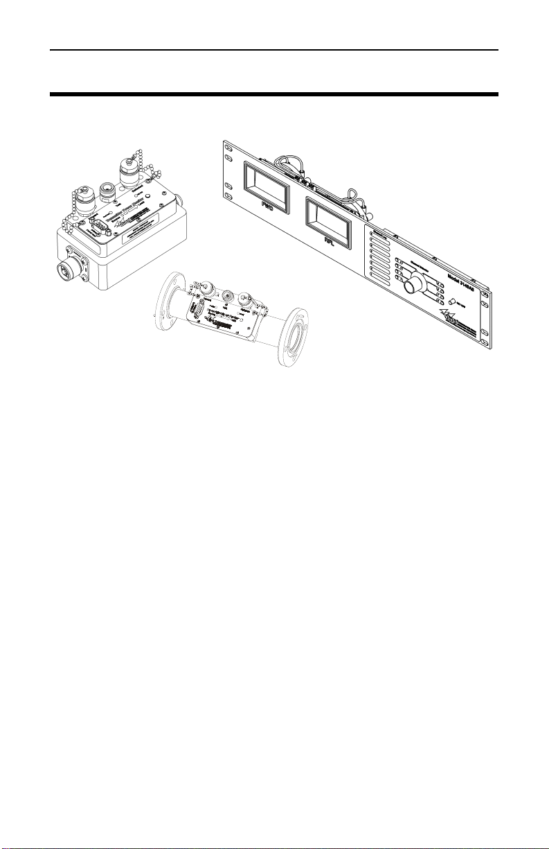
Introduction
3140 Panel
TPM7
TPM1
Chapter 1 Introduction
The Transmitter Power Monitor (TPM) is the latest broadcast solution
from Bird. Calibrated coupling ports and accurate power measure
ment combined in the same unit provides for easy use and accurate
readings. The TPM is the first inline power monitor that can be cali
brated in-line and on site minimizing downtime and optimizing on-air
time. In addition, a simplified interface allows for a high level of
customization and integration.
-
-
Purpose and Function
The TPM is used to measure power signals in broadcast systems. It is
used directly in line with the system being tested. It’s output provides
a linear DC voltage output from 0 to 4 volts allowing for a wide variety
of interface options. It’s in-line calibration capability allows for greater
accuracy in a single application (with an accurate power reference) and
its integrated non-directional coupler allows for signal analysis in
minimal space requirements. It is available in 7/8”, 1 5/8”, and 3 1/8”,
50 ohm lines for FM, VHF, and UHF broadcast frequencies.
When combined with a Bird model 3140A4 or 3140A8 Transmit Power
Meter (TPM) display, a complete adjustment system is achieved. The
display supplies a visual indication of Forward and Reflected power
being sampled by the inline TPM. Multiple TPM’s can be selected
(only one per channel setting) to give the operator an overall condition
of the transmitter system.
1
Page 12

Bird Electronics Corporation
2
Page 13

Installing & Operating Instructions - TPM
To Source
Operation LED
Calibration Cover
FWD Port
RFL
Port
Test
Port
Calibration Cover
Note: Figure shown with terminations assembled.
To Load
Communication
Connector
Figure 1
TPM
TPM1 Shown
Chapter 2 Installing & Operating Instructions - TPM
Note: The label on the top of the unit identifies the
connectors and ports. They are defined as follows:
Connect to the source of the RF signal
(transmitter side)
Connect to the load of the RF signal
(antenna/dummy load)
The forward directional coupler port. Terminate
this port in 50 ohms at all times.*
The reflected directional coupler port. Terminate
this port in 50 ohms at all times.*
A non directional sample port. No termination is
required.
SOURCE
LOAD
FORWARD
REFLECTED
TEST
* - If these ports are not terminated in 50 ohms, power
measurements will not be accurate.
Note: TPM units are terminated at the time of assembly.
3
Page 14

Bird Electronics Corporation
1
69
5
Pin 4 -
Power Supply
Ground
Figure 2
DB-9
Connector
Installing the TPM
The TPM has two RF connectors (Source and Load) that connect to the
transmission line, three test port connectors that are type N female
connectors (Forward, Reflected, and Test), and one nine-pin subminia
ture communication connector (DB-9 Male).
1. Do the following:
• Connect the RF connector labeled Source to the transmitter
side of the transmission line.
• Connect the RF connector labeled Load to the antenna or load
side of the transmission line.
• Use an appropriate coupling kit to secure the TPM in place.
2. Connect the DB-9 connector to a single channel on Model 3140A
power meter panel, or to an alternate appropriate power supply
and voltmeters that will indicate the forward and reflected power.
Note: The chart below Figure 2 identifies the signals on
each pin of the DB-9 connector.
-
Pin Description
1 Forward Voltage Output, 0 to 5 VDC, 1.0 kohm impedance
2 Ground
3 Reflected Voltage Output, 0 to 5 VDC, 1.0 kohm impedance
4 Power Supply Ground
5 DC Power Input, +11 to +18 VDC, <0.1 A current draw
6 Ground
7 Ground
8 Ground
9 Zero Calibration. DO NOT ground this pin. Leave this pin floating.
4
Note: Above 4VDC, the accuracy spec does not apply.
CAUTION
Pin 4 must be connected to power supply ground,
other grounds can be left open if desired.
Page 15

Installing & Operating Instructions - TPM
Normal Operation
Note: Coupler ports must be terminated to ensure accurate
power measurements. Terminate both forward and reflected
coupler ports in 50 ohms. Failure to terminate these ports will
result in inaccurate power measurements.
1. Install the TPM to the transmission line. Refer to “Installing
the TPM” on page 4.
2. Apply DC input power to the TPM.
3. Apply RF power to the TPM.
4. Use a voltmeter to measure the forward voltage and reflected
voltage.
Note: These voltages will be between 0 V (no power) and 4.0
V (full scale power). The forward and reflected voltages are linear.
Note: The full scale reflected power is 1/10 the value of the
full scale forward power.
5
Page 16

Bird Electronics Corporation
6
Page 17

Installing & Operating Instructions - 3140A Panel
FWD
Meter
Power
Button
DB9 Connections
Switch Notation Area
Meter
Adjustment
Pot
Channel
Selector
RFL Meter
Front View
DB9 Connections
Rear View
Meter
Adjustment
Pot
Meter
Adjustment
Pot
Zero Calibrate
Switch
Meter
Adjustment
Pot
Zero
Calibrate
Switch
Figure 3
3140 Panel
Note: 3140A8 shown.
Chapter 3 Installing & Operating Instructions - 3140A Panel
The 3140A is the standard display and power supply for the TPM. It
comes in both 4 Channel TPM and 8 Channel TPM models. It fits in a
standard 2U rack and requires a single 15V power supply (supplied
with panel).
DB9 are not serial connections. Serial connections to
CAUTION
them could damage the equipment.
7
Page 18

Bird Electronics Corporation
FWD/RFL
Meter
Meter Adj
Pot
Channel
Selector
Power
Button
Zero
Calibrate
Switch
DB9
Connection
Provides visual indication of measured power for
selected TPM.
Provides full scale meter calibration.
Selects either one of four (3140A4) or one of eight
(3140A8) connected TPM’s.
Applies DC input power to panel meter.
Grounds pin 9 to Zero calibrate the selected TPM.
Interface connection to TPM’s. Provides power and
Zero adjust to connected TPM’s. Receives TPM
output to drive meters.
Installing the Panel
1. Place panel in an empty slot on the rack and attach with mounting
screws (optional).
2. Connect the panel to a power supply.
3. Attach a TPM to one of the available channels on the back of the panel.
4. Label what TPM is attached to which channel in the switch notation area on the front of the panel.
Note: User should note each unit’s full scale power and
location in the notation area. Use a water soluble marker to
avoid permanent entries.
5. Repeat steps 3 and 4 for other TPM’s, if necessary.
6. Turn the panel on.
Note: All TPMs are powered, but only one TPM output is
displayed at a time.
7. Select the desired TPM to be measured by using the channel selector.
Note: The pots adjust the meter independently of TPM
calibration. The appropriate meter scale (1/2.5/5) must be
used with each TPM.
8
Page 19

Calibration
1
69
5
Pin 9
Figure 4
Pin 9
Chapter 4 Calibration
CAUTION
A Bird Calibration Kit is recommended for this procedure.
Performing a calibration with anything other than a Bird
Calibration Kit voids Bird’s accuracy guarantee.
Performing a field calibration will void any remaining warranty
on this product. Bird recommends waiting until the terms of the
warranty have passed before performing a field calibration.
Every calibration procedure will finish by providing a table of voltages
that correspond to power levels at the calibration frequency (f
be up to the user to use those voltages to generate an equation or fill in
a look up table on whatever they choose to use as an output.
). It will
0
Zero Calibrating
Note: This procedure can be performed any time the RF is
off and the TPM is on. There is no need to cycle power again on
the TPM.
Do one of the following:
• Locate pin 9 on the TPM’s DB9 connector and short it to ground.
• If connected to a display panel, press the zero calibration
switch. Refer to Figure 4 for Zero Calibration Switch location.
Note: Zero calibrate will set both the FWD and RFL at the
same time.
9
Page 20

Bird Electronics Corporation
Figure 6
Forward Calibration Set-Up
TPM
Connector
Figure 7
Reflected Calibration Set-Up
Calibration Standard
Figure 5
Calibration Kit
Passive Calibration
Calibrate the TPM on the transmitter it is monitoring. Also a reference power meter is needed to measure the output of the test port on
the TPM (model 7006A250). This calibration can be performed while
transmitting on air (forward only) or into a dummy load. Coupling
calibration data for the TPM is also needed.
By using several different power levels, an equation or lookup table
can be generated for the voltage output of the TPM as a function of
power level at the frequency of calibration.
1. Install the TPM to the transmission line. Refer to “Installing the
TPM” on page 4.
2. Remove the load from the Fwd testport.
3. Connect the calibration standard to the Fwd testport.
4. Apply RF power.
5. Record the transmitter frequency displayed and find the listing
closest to it on the TPM’s coupling calibration data card.
Note: Make note of the calibration factor.
6. Enter the calibration factor into the calibration standard’s offset
function.
7. Measure the power on the calibration standard and voltage on the
TPM output simultaneously.
8. Record the voltage verses power.
9. Turn the unit around and repeat steps 1 to 7 for Reflected calibration.
Note: Reflected fullscale is 1/10th of forward fullscale.
10
Note: Calibrating the reflected port is often optional.
Check with the FCC or other ruling body to determine if it is
necessary or not.
Page 21

Calibration
Active Calibration
The active method will recalibrate the TPM completely. This procedure will void the calibration and accuracy specifications for the unit.
The accuracy will be based on the accuracy of the reference power
meter used for this procedure. In addition to the equipment needed for
the active calibration, a Bird 6A340-ADJ Potentiometer Adjustment
Tool to adjust the potentiometers on the TPM is also needed.
Set the transmitter’s RF output to a desired power level using the reference meter on the test port and the test port calibration data. Then,
using a Bird 6A340-ADJ Potentiometer Adjustment Tool, turn the
potentiometers until the desired voltage output is reached. Extra data
points can be taken at different power levels to confirm the linearity
and generate a lookup table to drive the rest of the power levels.
The benefit of this calibration method is that the customer can set the
output voltage they want to drive their external meter. With the other
calibration methods, the customer simply uses TPM output voltages
as set at the factory.
1. Install the TPM to the transmission line. Refer to “Installing the
TPM” on page 4.
2. Remove the load from the Fwd testport.
3. Connect the calibration standard to the Fwd testport.
4. Apply RF power.
5. Record the transmitter frequency displayed and find the listing
closest to it on the TPM’s calibration data card.
Note: Make note of the calibration factor.
6. Enter the calibration factor into the calibration standard’s offset
function.
7. Break the seal over the Fwd Cal hole.
8. Adjust the potentiometer manually until the voltage is such that
the calibration standard reads fullscale power = 4.00V.
Example: If the power is exactly 50% of fullscale, adjust the
potentiometer to get V=2.00V.
9. Repeat steps 1 to 9 for Reflected calibration.
Note: Calibrating the reflected port is often optional.
Check with the FCC or other ruling body to determine if it is
necessary or not.
11
Page 22

Bird Electronics Corporation
Figure 8
Calibration
Data Card
Transmitter
Frequency
Fwd Coupling
Offset at 195 MHz
Rfl Coupling
Offset at 195 MHz
12
Page 23

Performance Specifications
Chapter 5 Performance Specifications
T ransmitter Power Meter (TPM)
Model Naming Table
Line Size and Interface Style
7xy = 7/8” with QC connectors, where x is
the input connector and y is the output
connector. Possibl e values of x and y are:
A =N(F) B = N(M)
C = LC(F) D = 7/8” Flange
H = 7-16 DIN(F) J = 7-16 DIN(M)
K = UHF(F) L = UHF(M)
1 = 1-5/8” Flanged 1U = 5/ 8 ”
Unflanged “recessed”
1UF = 1-5/8” Unflanged “flush”
3 = 3-1/8” Flanged 3U = 3- 1/ 8 ”
Unflanged “recessed”
3UF = 3-1/8” Unflanged “flush”
Frequency
Band*
L = 54 - 88 MHz
F = 88 - 108 MHz
H = 174 - 216 MHz
U = 470 - 806 MHz
Power
Range*
V = Very Low
L = Low
M = Medium
H = High
S = Very High
Note: Models TPM 3 x - LV and models TPM x - US are
not offered for sale.
Frequency Range - Model dependent. See table above
Forward Fullscale Power - Model dependent. See table below.
Note: Maximum safe line power may be lower than
fullscale power. See Line Section Max RF Power vs Frequency
table on page 20 for recommended max safe line powers at the
active frequency.
13
Page 24

Bird Electronics Corporation
Line Size Power Range Fullscale (kW)
7/8”
1 - 5/8”
3 - 1/8”
Very Low
Low
Medium
High
Very High
Very Low
Low
Medium
High
Very High
Very Low
Low
Medium
High
Very High
0.1
0.5
1.0
2.5
5.0
0.5
1.0
2.5
5.0
10.0
2.5
5.0
10.0
25.0
50.0
RF Specs
FWD / RFL Ratio Reflected fullscale power is 1/10 of forward
fullscale power.
Peak/Average Ratio 10 dB min*
Main Line Insertion Loss 0.2 dB max, 0.08 dB typical
Main Line VSWR 1.1 max
Testport VSWR 1.5 max, 1.3 typical
Accuracy ± 5% of reading (2s) after zeroing sensor, if
calibrated by Bird. This does not include
user mismatch uncertainty and user
voltmeter uncertainty. If not calibrated by
Bird, add the uncertainty of the calibration
method and reference standard. Derate
accuracy by 1% if not at 25 ± 10 °C.
Dynamic Range 16 dB min
Directivity, Rfl 26 dB min, 30 dB typical
Measurement type In-line, true-average power
Calibration Unit can be calibrated by user by adjusting
pot to get 4V output for a fullscale RF input.
Recommended Cal Interval 1 year
* - Peak to Average ratio is specified based on the fullscale
power of the specific TPM model. For example, a TPM with a
fullscale forward power rating of 1 kW will provide accurate
readings for signals with peak powers up to 10 kW. If the TPM is
operated below its fullscale power rating, the peak / average
rating will increase by the difference between the fullscale value
and the operating power. For example, if a 1 kW TPM is operated at 700 W, the new peak/ average ratio would be 11.5 dB.
14
Page 25

Performance Specifications
Interface Specs
Main line Diameters and center conductor setbacks per Bird
drawings.
Connectors One DB9(M), three N(F)
DB9 connector pinout
Pin 1 = “FWD” Analog output for forward RF power. 0 – 5.0 Vdc
proportional to RF power, 1 kohm
impedance. Fullscale RF input = 4.0V output.
Pin 3 = “RFL” Analog output for reflected RF power. 0 – 5.0 Vdc
proportional to RF power, 1 kohm
impedance. Fullscale RF input = 4.0V output.
Pin 5 = “Power” Power supply input. +11 to +18 Vdc, < 0.1 A.
Pin 9 = “Zeroline” Short this pin to ground to zero out any input offsets.
Normally floating. Unit can be zeroed whenever the unit is
powered up and there is no RF power being applied.
Pins 2,4,6–8 = GND
N(F) Testports Ports are labeled Forward, Test, and Reflected. Forward
and reflected testports include attached loads. These
testports must be terminated with the load, or some other
good termination such as a power sensor, during normal
operation to prevent measurement errors. Loads can
removed from the unit if desired without affecting calibrati on.
Forward Testport output is a sample of the forward RF signal.
Test Testport output is a nondirectional sample of the RF.
Reflected Testport output is a sample of the reflected RF signal.
Environmental Specs
T emperature, Operating 0 to +50 °C (32 to 122 °F)
T emperature, Storage –20 to +80 °C (–4 to +176 °F)
Altitude, Max 3,000 m (10,000 ft) above sea level
Humidity, Max 95% noncondensing
CE CE compliant
ROHS ROHS compliant
Dimensions Refer to “Dimensions” on page 16.
Weight See table below.
Line Size Weight, Max
7/8” 3 lbs (1.5 kg)
1-5/8”, unflanged 3.5 lbs (1.6 kg)
1-5/8”, flanged 5.5 lbs (2.5 kg)
3-1/8”, unflanged 4.5 lbs (2.0 kg)
3-1/8”, flanged 8 lbs (3.6 ks)
15
Page 26

Bird Electronics Corporation
Figure 9
TPM7
Figure 10
Unflanged
1-5/8” TPM
Figure 11
Flanged
1-5/8” TPM
Dimensions
16
Page 27

Performance Specifications
Figure 12
Unflanged
3-1/8” TPM
Figure 13
Flanged
3-1/8” TPM
17
Page 28

Bird Electronics Corporation
3140A Meter Panel
General Specs
Function Provide power to multiple TPM units. Display Fwd
and Rfl readings from one of the connected TPMs,
chosen with a switch.
Models
3140A4 Supports up to 4 TPMs
3140A8 Supports up to 8 TPMs
Display Two backlit analog meters. One displays forward
power as measured on the selected TPM, the other
displays reflected power. Which TPM’s readings are
displayed on the meters is controlled by a switch on
the front panel.
Power
requirements
TPM Connectors DB9(F), either 4 or 8 connectors on the back panel
DB9 Pinout Same as TPM DB9 pinout
Calibration Panel Meters can be calibrated independently of the
Units are provided with Bird 5A2436 power supply.
5A2436 requires 115/230 Vac @ 50/60 Hz, < 1.0 A
Panel requires 11 to 16 Vdc, < 1.0 A. Jack connector
is compatible with 5A2436.
TPMs. There is one user-adjustable pot for each meter.
Environmental Specs
Temperature, Operating 0 to +50 °C (32 to 122 °F)
Temperature, Storage –20 to +80 °C (–4 to +176 °F)
Altitude, Max 3,000 m (10,000 ft) above sea level
CE CE compliant
ROHS ROHS compliant
Dimensions 2U EIA
Weight, Max 2.5 lbs (1.0 kg)
18
Page 29

Maintenance
Chapter 6 Maintenance
Inspection and Cleaning
This unit requires only simple and routine maintenance.
WARNING
Disconnect the unit from the RF power source and
the ac line before any disassembly. The potential for
electrical shock exists.
CAUTION
Do not use harsh or abrasive detergents for
cleaning.
1. Wipe off dust and dirt regularly. Use a soft, clean cloth dampened
with mild detergent.
Check connectors, connector pins, and cables for damage. If needed,
clean the connectors using a self-drying contact cleaner that leaves no
residue.
ROHS
Part
Name
Copper
Alloy
O: Indicates that this toxic or hazardous substance contained in all of the
homogeneous materials for this part is below the limit requirement in
SJ/T11363-2006.
X: Indicates that this toxic or hazardous substance contained in at least one of
the homogeneous materials used for this part is above the limit requirements in
SJ/T11363-2006.
Toxic or hazardous Substances and Elements
Lead
(Pb)
Mercury
(Hg)
XOO O OO
Cadmium
(Cd)
Hexavalent
Chromium
(Cr(VI))
Polybrominated
biphenyls
(PBB)
Polybrominated
diphenyl
ethers
(PBDE)
19
Page 30

Bird Electronics Corporation
"
100
1000
10000
(kW)
Line Section Max Power vs. Frequency
6-1/8
4-1/16" & 4-1/2"
3-1/8"
1-5/8"
7/8"
0.1
1
10
1 10 100 1000 10000
Max Average Powe
r
Frequency (MHz)
20
Page 31

Maintenance
Troubleshooting
The TPM has no operator serviceable parts. Any required service must
be performed at an authorized service facility.
The table below contains troubleshooting information for problems
which can occur during normal operation. This manual cannot list all
malfunctions that may occur or their corrective actions. If a problem is
not listed or is not corrected by the listed actions, notify a qualified
service center.
Transmitter Power Monitor
Problem Possible Cause Correction
Power LED does
not illuminate
High VSWR Dirty connectors Clean connectors
No dc power Check power
source, and cable
Defective LED Return the unit to
an authorized
service center
Defective
connectors
Shorted or open
transmission line
Replace connectors
Have the line
serviced.
3140 Panel
Problem Possible Cause Correction
Display does not
light
Unit is not turned on Set AC Power
Switch to ON
Unit is not plugged inConnect ac power
cord
21
Page 32

Bird Electronics Corporation
Parts List
Customer Replacement Part Consists of Description
RPK7006B112 - Replacement
Digital Board
RPK7006A1000 - Replacement Lid 7006A109 Metal Lid
2-T-MN-2 - Replacement
Terminations
5A2211-2 - Replacement
Calibration Data
5A2264-09-MF-25
Replacement Cable
6A340-ADJ - Calibration
Adjustment Tool
7006A250 - TPM Transfer Standard 7006A250 Calibration
7006B112 Digital PC
Board
920-RPK7006B112 Instruction
Sheet
7006A124 Label
5A2833-LPC020CTP Light Pipe
5A2833-RTN150 Rubber Ring
920-RPK7000A1000 Instruction
Sheet
2-T-MN-2 Terminations
5A2211-2 Data
5A2264-09-MF-25 Cable, 9-pin
Male/Female,
25 ft
6A340-ADJ Calibration
Tool
Standard
22
Page 33

Declaration of Conformity
Maintenance
Manufacturer: Bird Technologies Group
Type Product: Panel Meter: 3140A4, 3140A8
Line Size and Interface Style Frequency Band* Power Range
7xy = 7/8” with QC connectors, where x is the
input connector and y is the output connector.
Possible values of x and y are:
A =N(F) B = N(M)
C = LC(F) D = 7/8” Flange
H = 7-16 DIN(F) J = 7-16 DIN(M)
K = UHF(F) L = UHF(M)
1 = 1-5/8” Flanged 1U = 5/8”
1UF = 1-5/8” Unflanged “flush”
3 = 3-1/8” Flanged 3U = 3-1/8” Unflanged
3UF = 3-1/8” Unflanged “flush”
The undersigned hereby declares, on behalf of Bird Technologies Group of Cleveland,
Ohio, that the above referenced products, to which this declaration relates, are in con
formance with the provisions of the following standards.
In accordance with EMC Directive (2004/108/EC)
30303 Aurora Road
Cleveland, Ohio 44139-2794
Transmitter Power Monitor: TPM series (see below for numbering)
L = 54 - 88 MHz
F = 88 - 108 MHz
H = 174 - 216 MHz
U = 470 - 806 MHz
Unflanged “recessed”
“recessed”
V = Very Low
L = Low
M = Medium
H = High
S = Very High
-
• European Standard EN 61326-1:2006; -2-1:2006 - Electrical Equipment for Mea-
surement, Control and Laboratory use, EMC Requirements - Parts 1 and 2-1.
• European Standard EN 61000-3-2:2000; -3-3:1995 - Electromagnetic Compatibil-
ity-Parts 3 Testing and measurement techniques - Sections 2 and 3.
In accordance with Low Voltage Directive (73/23/EEC), 1973 including Amendment (93/
68/EEC), 1993
• European Standard EN 61010-1:2001 - Safety Retirements for Electrical
Equipment for Measurement, Control and Laboratory Use
The technical documentation supporting compliance with these directives is maintained
at Bird Technologies Group, 30303 Aurora Road, Cleveland, Ohio 44139.
Steve Beitscher
Director of Quality
Bird Technologies Group
23
Page 34

Bird Electronics Corporation
Customer Service
If you need to return the unit prior to use, please contact the Bird
Technologies Sales department.
For a return after a unit has been put into use, contact the Bird Service Center for a return authorization. All instruments returned must
be shipped prepaid and to the attention of Bird Service Center.
Service Facility
Bird Service Center
30303 Aurora Road
Cleveland (Solon), Ohio 44139-2794
Phone: (440) 519-2298
Fax: (440) 519-2326
E-mail: bsc@bird-technologies.com
Sales Facilities
For the location of the Sales Office nearest you, give us a call or visit
our Web site at:
http://www.bird-electronic.com
24
Page 35

Limited Warranty
All products manufactured by Seller are warranted to be free from
defects in material and workmanship for a period of one year, unless
otherwise specified, from date of shipment and to conform to applica
ble specifications, drawings, blueprints and/or samples. Seller’s sole
obligation under these warranties shall be to issue credit, repair or
replace any item or part thereof which is proved to be other than as
warranted; no allowance shall be made for any labor charges of Buyer
for replacement of parts, adjustment or repairs, or any other work,
unless such charges are authorized in advance by Seller.
If Seller’s products are claimed to be defective in material or workmanship or not to conform to specifications, drawings, blueprints and/
or samples, Seller shall, upon prompt notice thereof, either examine
the products where they are located or issue shipping instructions for
return to Seller (transportation-charges prepaid by Buyer). In the
event any of our products are proved to be other than as warranted,
transportation costs (cheapest way) to and from Seller’s plant, will be
borne by Seller and reimbursement or credit will be made for amounts
so expended by Buyer. Every such claim for breach of these warranties
shall be deemed to be waived by Buyer unless made in writing within
ten days from the date of discovery of the defect.
The above warranties shall not extend to any products or parts thereof
which have been subjected to any misuse or neglect, damaged by acci
dent, rendered defective by reason of improper installation or by the
performance of repairs or alterations outside of our plant, and shall
not apply to any goods or parts thereof furnished by Buyer or acquired
from others at Buyer’s request and/or to Buyer’s specifications. Rou
tine (regularly required) calibration is not covered under this limited
warranty. In addition, Seller’s warranties do not extend to the failure
of tubes, transistors, fuses and batteries, or to other equipment and
parts manufactured by others except to the extent of the original man
ufacturer’s warranty to Seller.
The obligations under the foregoing warranties are limited to the precise
terms thereof. These warranties provide exclusive remedies, expressly in
lieu of all other remedies including claims for special or consequential
damages. SELLER NEITHER MAKES NOR ASSUMES ANY OTHER
WARRANTY WHATSOEVER, WHETHER EXPRESS, STATUTORY,
OR IMPLIED, INCLUDING WARRANTIES OF MERCHANTABILITY
AND FITNESS, AND NO PERSON IS AUTHORIZED TO ASSUME
FOR SELLER ANY OBLIGATION OR LIABILITY NOT STRICTLY IN
ACCORDANCE WITH THE FOREGOING.
-
-
-
-
25
Page 36

Bird Technologies
26
 Loading...