

Page 1

Broadcast Power
Monitor Series BPM-E
Model 3129 Digital Display
OPERATING INSTRUCTIONS
©Copyright 2012
Instruction Book P/N 920-7005ABPME Rev. H
Java® is a registered trademark of Sun Microsystems, Inc.
by Bird Electronic Corporation
Thruline® is a registered trademark of
Microsoft® and Windows® are registered
trademarks of the Microsoft Corporation
Bird Electronic Corporation
Page 2

This page is not blank
16
Page 3

Safety Precautions
The following are general safety precautions that are not necessarily related to
any specific part or procedure, and do not necessarily appear elsewhere in this
publication. These precautions must be thoroughly understood and apply to all
phases of operation and maintenance.
WARNING
Keep Away From Live Circuits
Operating Personnel must at all times observe general safety precautions. Do
not replace components or make adjustments to the inside of the test
equipment with the high voltage supply turned on. To avoid casualties, always
remove power.
WARNING
Shock Hazard
Do not attempt to remove the RF transmission line while RF power is present.
WARNING
Do Not Service Or Adjust Alone
Under no circumstances should any person reach into an enclosure for the
purpose of service or adjustment of equipment except in the presence of
someone who is capable of rendering aid.
WARNING
Safety Earth Ground
An uninterruptible earth safety ground must be supplied from the main power
source to test instruments. Grounding one conductor of a two conductor
power cable is not sufficient protection. Serious injury or death can occur if
this grounding is not properly supplied.
WARNING
Resuscitation
Personnel working with or near high voltages should be familiar with modern
methods of resuscitation.
WARNING
Remove Power
Observe general safety precautions. Do not open the instrument with the
power on.
i
Page 4
Safety Symbols
WARNING
Warning notes call attention to a procedure, which if not correctly performed,
could result in personal injury.
CAUTION
Caution notes call attention to a procedure, which if not correctly performed,
could result in damage to the instrument.
Note: Calls attention to supplemental information.
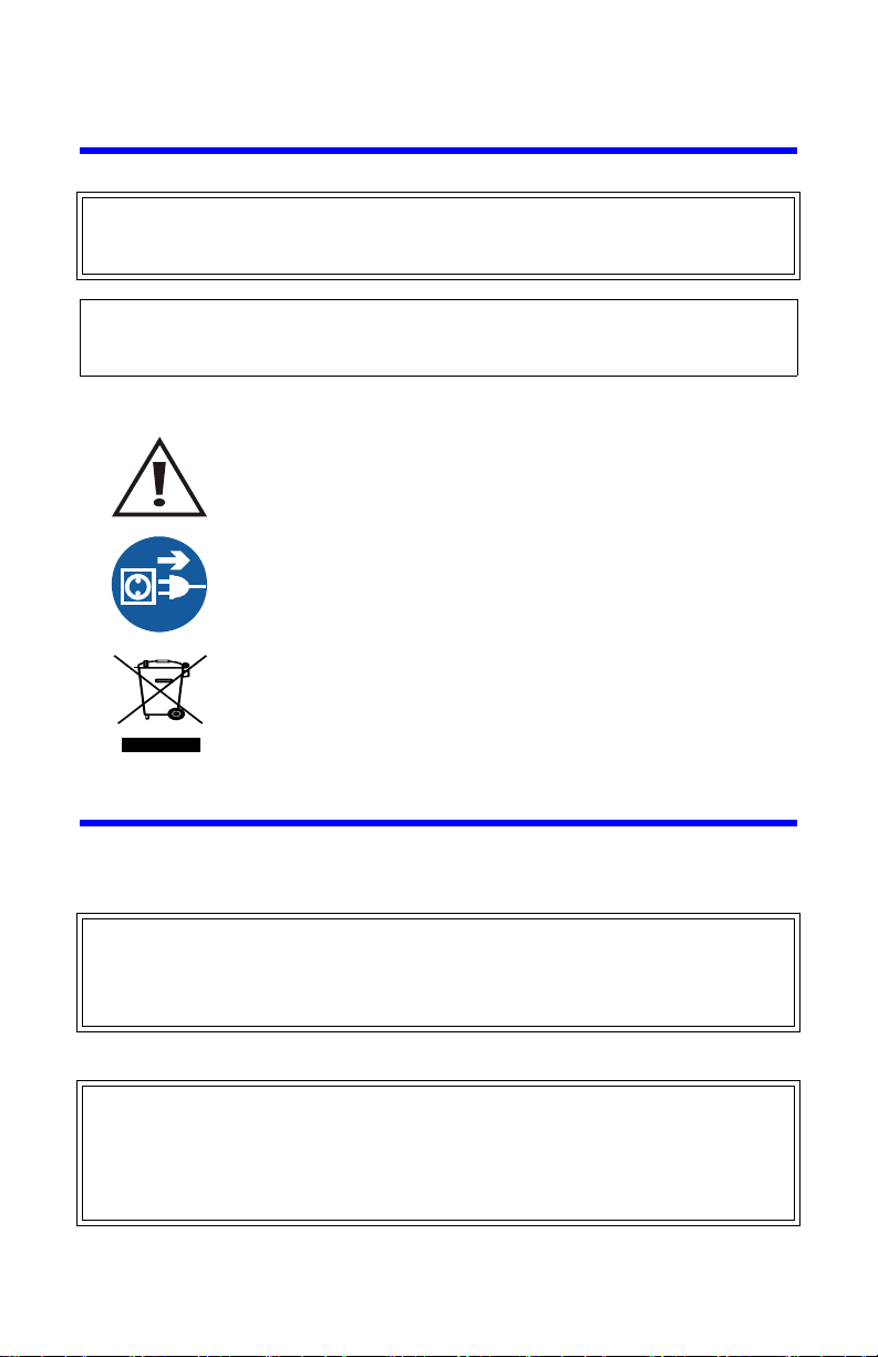
The caution symbol appears on the equipment indicating
there is important information in the instruction manual
regarding that particular area.
This symbol appears on the equipment and indicates that the
AC power cord should be removed before servicing the unit.
This symbol appears on the equipment and indicates the
requirement for separate collection of discarded electrical
and electronic equipment in accordance with the European
Union Directive 2002/96/EC. Refer to the Bird web site for
more information.
Warning Statements
The following safety warnings appear in the text where there is danger to operating and maintenance personnel, and are repeated here for emphasis.
WAR NING
Leaking RF energy is a potential health hazard. Never attempt to connect or
disconnect equipment from the transmission line while RF power is being applied.
Severe burns, electrical shock, or death can occur.
See page 11.
WAR NING
High RF voltage and energy is always present in the RF Test Port when the system is
operating. Do not operate the system if the BPM-E RF Test Port is open. Close the port
with a dummy plug or a suitable sampling plug. Failure to comply may result in severe
burns, electrical shock, or death.
See page 12.
ii
Page 5

WARNING
Dangerous RF voltage. Do not connect or apply an RF signal to the BPM-E
during equipment setup. Failure to comply may result in severe burns, loss of
use of limbs, or death.
See pages 19, 21, and 22.
WARNING
Disconnect the unit from the RF power source and the ac line before any
disassembly. The potential for electrical shock exists.
See page 41.
Caution Statements
The following equipment cautions appear in the text and are repeated here for
emphasis.
CAUTION
BPM-E signal sensing couplers are fixed in place. Do not attempt to remove or
rotate the couplers. They are calibrated and oriented at the factory and are not
designed to be rotated or removed by the end user. Failure to comply may
result in loss of calibration and accuracy, and in permanent damage to the unit.
See pages 12 and 27.
CAUTION
The DC voltage provided by the 3129 Digital Display power/alarm port should
only be used to power the BPM-E. Do not use the 3129 DC source to supply
power to anything else.
See page 15.
CAUTION
Network connections require specific address and protocol information. Have a
qualified IT or network professional perform the BPME ethernet setup. Failure to
comply may result in loss of network communication or the inability to
communicate with the BPME.
See page 22.
CAUTION
Do not use harsh or abrasive detergents for cleaning.
See page 41.
iii
Page 6

Safety Statements
USAGE
ANY USE OF THIS INSTRUMENT IN A MANNER NOT
SPECIFIED BY THE MANUFACTURER MAY IMPAIR THE
INSTRUMENT’S SAFETY PROTECTION.
USO
EL USO DE ESTE INSTRUMENTO DE MANERA NO
ESPECIFICADA POR EL FABRICANTE, PUEDE ANULAR LA
PROTECCIÓN DE SEGURIDAD DEL INSTRUMENTO.
BENUTZUNG
WIRD DAS GERÄT AUF ANDERE WEISE VERWENDET ALS VOM
HERSTELLER BESCHRIEBEN, KANN DIE GERÄTESICHERHEIT
BEEINTRÄCHTIGT WERDEN.
UTILISATION
TOUTE UTILISATION DE CET INSTRUMENT QUI N’EST PAS
EXPLICITEMENT PRÉVUE PAR LE FABRICANT PEUT
ENDOMMAGER LE DISPOSITIF DE PROTECTION DE
L’INSTRUMENT.
IMPIEGO
QUALORA QUESTO STRUMENTO VENISSE UTILIZZATO IN
MODO DIVERSO DA COME SPECIFICATO DAL PRODUTTORE
LA PROZIONE DI SICUREZZA POTREBBE VENIRNE
COMPROMESSA.
iv
Page 7

SERVICE
SERVICING INSTRUCTIONS ARE FOR USE BY SERVICE TRAINED PERSONNEL ONLY. TO AVOID DANGEROUS
ELECTRIC SHOCK, DO NOT PERFORM ANY SERVICING
UNLESS QUALIFIED TO DO SO.
SERVICIO
LAS INSTRUCCIONES DE SERVICIO SON PARA USO
EXCLUSIVO DEL PERSONAL DE SERVICIO CAPACITADO. PARA
EVITAR EL PELIGRO DE DESCARGAS ELÉCTRICAS, NO
REALICE NINGÚN SERVICIO A MENOS QUE ESTÉ
CAPACITADO PARA HACERIO.
WARTUNG
ANWEISUNGEN FÜR DIE WARTUNG DES GERÄTES GELTEN
NUR FÜR GESCHULTES FACHPERSONAL.
ZUR VERMEIDUNG GEFÄHRLICHE, ELEKTRISCHE SCHOCKS,
SIND WARTUNGSARBEITEN AUSSCHLIEßLICH VON
QUALIFIZIERTEM SERVICEPERSONAL DURCHZUFÜHREN.
ENTRENTIEN
L’EMPLOI DES INSTRUCTIONS D’ENTRETIEN DOIT ÊTRE
RÉSERVÉ AU PERSONNEL FORMÉ AUX OPÉRATIONS
D’ENTRETIEN. POUR PRÉVENIR UN CHOC ÉLECTRIQUE
DANGEREUX, NE PAS EFFECTUER D’ENTRETIEN SI L’ON N’A
PAS ÉTÉ QUALIFIÉ POUR CE FAIRE.
ASSISTENZA TECNICA
LE ISTRUZIONI RELATIVE ALL’ASSISTENZA SONO PREVISTE
ESCLUSIVAMENTE PER IL PERSONALE OPPORTUNAMENTE
ADDESTRATO. PER EVITARE PERICOLOSE SCOSSE
ELETTRICHE NON EFFETTUARRE ALCUNA RIPARAZIONE A
MENO CHE QUALIFICATI A FARLA.
v
Page 8

RF VOLTAGE MAY BE PRESENT IN RF ELEMENT SOCKET - KEEP
ELEMENT IN SOCKET DURING OPERATION.
DE LA TENSION H.F. PEAT ÊTRE PRÉSENTE DANS LA PRISE DE
L'ÉLÉMENT H.F. - CONSERVER L'ÉLÉMENT DANS LA PRISE LORS
DE L'EMPLOI.
HF-SPANNUNG KANN IN DER HF-ELEMENT-BUCHSE ANSTEHEN ELEMENT WÄHREND DES BETRIEBS EINGESTÖPSELT LASSEN.
PUEDE HABER VOL TAJE RF EN EL ENCHUFE DEL ELEMENTO RF MANTENGA EL ELEMENTO EN EL ENCHUFE DURANTE LA
OPERACION.
IL PORTAELEMENTO RF PUÒ PRESENTARE VOLTAGGIO RF TENERE L'ELEMENTO NELLA PRESA DURANTE IL
FUNZIONAMENTO.
vi
Page 9

About This Manual
1 2 3
4
BPME ___ ___ - ___ ___
This manual covers the operating and maintenance instructions for the following models:
3129 BPME
Figure 1 BPM-E Model Identification
Item Description Options
1 Line Section 1 = 1 - 5/8”
2 Line Interface U = Unflanged, Recessed Center Cond.
3 Frequency Band VL = 45 - 88 MHz
4 Power L = Low
3 = 3 - 1/8”
4 = 4 - 1/16”
4A = 4 - 1/2”
6 = 6 - 1/8”
UF = Unflanged, Flush Center Cond.
D = Dielectric Flanged
M = Myat Flanged
leave blank = Flanged, EIA standard
V = 88 - 230 MHz
U = 470 - 890 MHz
M = Medium
H = High
X = Extra Low
Refer to power ranges for each line section diameter (See “RF Power Ratings” on page 48)
vii
Page 10

Figure 2 BPM-E7 Model Identification
1 2 3
4 5
6
BPME 7 ___ ___ - ___ ___ ___
Item Description Options
1 Line Section 7 = 7/8”
2 Input Connector A = N (F)
B = N (M)
C = LC (F)
D = 7/8” EIA
H = 7/16 DIN (F)
J = 7/16 DIN (M)
K = UHF (F)
L = UHF (M)
3 Output Connec-
tor
A = N (F)
B = N (M)
C = LC (F)
D = 7/8” EIA
H = 7/16 DIN (F)
J = 7/16 DIN (M)
K = UHF (F)
L = UHF (M)
4 Frequency Band VL = 45 - 88 MHz
V = 88 - 230 MHz
U = 470 - 890 MHz
5 Power L = Low
M = Medium
H = High
refer to power ranges for each line
section diameter (See “RF Power
Ratings” on page 48)
6 Mounting P = Panel mount (for a 19 in. equip-
ment rack)
leave blank = Standard mounting
configuration
viii
Page 11

Changes to this Manual
We have made every effort to ensure this manual is accurate. If you
discover any errors, or if you have suggestions for improving this manual, please send your comments to our Solon, Ohio factory. This manual may be periodically updated. When inquiring about updates to
this manual refer to the part number and revision on the title page.
Literature Contents
Chapter Layout
Introduction — Identifies the parts and functions of the BPM-E and the 3129
Display Panel, and lists optional equipment available.
Theory of Operation — Describes the theory and features of the BPM-E and
the Display, including the alarm options.
Installation — Provides information on installing the BPM-E and 3129 Digital
Display at a site, as well as information on the cable connections and installation
instructions for the WebTool utility and the PCTool software.
Operating Instructions — Describes operation of the display and use of the
PCTool software and the WebTool software.
Maintenance — Lists basic troubleshooting information, routine maintenance
tasks for the BPM-E and the 3129 digital display, specifications, and parts lists.
ix
Page 12

x
Page 13

Table of Contents
Safety Precautions . . . . . . . . . . . . . . . . . . . . . . . . . . . . . . . . . . . . . . . . . i
Safety Symbols . . . . . . . . . . . . . . . . . . . . . . . . . . . . . . . . . . . . . . . . . . . . . . . . . . ii
Warning Statements . . . . . . . . . . . . . . . . . . . . . . . . . . . . . . . . . . . . . . . . . . . . . ii
Caution Statements . . . . . . . . . . . . . . . . . . . . . . . . . . . . . . . . . . . . . . . . . . . . . . iii
Safety Statements . . . . . . . . . . . . . . . . . . . . . . . . . . . . . . . . . . . . . . . . . . . . . . . iv
About This Manual . . . . . . . . . . . . . . . . . . . . . . . . . . . . . . . . . . . . . . . . vii
Changes to this Manual . . . . . . . . . . . . . . . . . . . . . . . . . . . . . . . . . . . . . . . . . . . ix
Literature Contents . . . . . . . . . . . . . . . . . . . . . . . . . . . . . . . . . . . . . . . . . . . . . . ix
Chapter Layout . . . . . . . . . . . . . . . . . . . . . . . . . . . . . . . . . . . . . . . . . . . . . . ix
Chapter 1 Introduction . . . . . . . . . . . . . . . . . . . . . . . . . . . . . . . . . . . . .1
Broadcast Power Monitor . . . . . . . . . . . . . . . . . . . . . . . . . . . . . . . . . . . . . . . . . 1
Features . . . . . . . . . . . . . . . . . . . . . . . . . . . . . . . . . . . . . . . . . . . . . . . . . . . . 1
Items Supplied . . . . . . . . . . . . . . . . . . . . . . . . . . . . . . . . . . . . . . . . . . . . . . . 1
Optional Items Available . . . . . . . . . . . . . . . . . . . . . . . . . . . . . . . . . . . . . . . 2
Digital Display . . . . . . . . . . . . . . . . . . . . . . . . . . . . . . . . . . . . . . . . . . . . . . . . . . 2
Features . . . . . . . . . . . . . . . . . . . . . . . . . . . . . . . . . . . . . . . . . . . . . . . . . . . . 2
Component Description . . . . . . . . . . . . . . . . . . . . . . . . . . . . . . . . . . . . . . . . . . 3
Chapter 2 Theory of Operation. . . . . . . . . . . . . . . . . . . . . . . . . . . . . . .7
General Theory . . . . . . . . . . . . . . . . . . . . . . . . . . . . . . . . . . . . . . . . . . . . . . . . . 7
Factors that Affect Power Reading Accuracy . . . . . . . . . . . . . . . . . . . . . . . . . 7
Alarm Response . . . . . . . . . . . . . . . . . . . . . . . . . . . . . . . . . . . . . . . . . . . . . . 8
Alarm Reset . . . . . . . . . . . . . . . . . . . . . . . . . . . . . . . . . . . . . . . . . . . . . . . . . 8
Alarm Latching . . . . . . . . . . . . . . . . . . . . . . . . . . . . . . . . . . . . . . . . . . . . . . . 8
VSWR Alarm . . . . . . . . . . . . . . . . . . . . . . . . . . . . . . . . . . . . . . . . . . . . . . . . . 8
Alarm on Zero Power . . . . . . . . . . . . . . . . . . . . . . . . . . . . . . . . . . . . . . . . . 9
High Power Alarm . . . . . . . . . . . . . . . . . . . . . . . . . . . . . . . . . . . . . . . . . . . . 9
Low Power Alarm . . . . . . . . . . . . . . . . . . . . . . . . . . . . . . . . . . . . . . . . . . . . 9
Chapter 3 Installation . . . . . . . . . . . . . . . . . . . . . . . . . . . . . . . . . . . . . 11
Unpacking and Inspection . . . . . . . . . . . . . . . . . . . . . . . . . . . . . . . . . . . . . . . . 11
Tools Required . . . . . . . . . . . . . . . . . . . . . . . . . . . . . . . . . . . . . . . . . . . . . . . . . 11
Mounting a BPM-E . . . . . . . . . . . . . . . . . . . . . . . . . . . . . . . . . . . . . . . . . . . . . . 11
BPM-E7 . . . . . . . . . . . . . . . . . . . . . . . . . . . . . . . . . . . . . . . . . . . . . . . . . . . . 12
Flanged Connector . . . . . . . . . . . . . . . . . . . . . . . . . . . . . . . . . . . . . . . . . . 13
Unflanged Connector . . . . . . . . . . . . . . . . . . . . . . . . . . . . . . . . . . . . . . . . 13
xi
Page 14

3129 Digital Display . . . . . . . . . . . . . . . . . . . . . . . . . . . . . . . . . . . . . . . . . . . . +14
Mounting a 3129 Digital Display . . . . . . . . . . . . . . . . . . . . . . . . . . . . . . . 14
AC Power Connector . . . . . . . . . . . . . . . . . . . . . . . . . . . . . . . . . . . . . . . 14
Alarm Interlocks . . . . . . . . . . . . . . . . . . . . . . . . . . . . . . . . . . . . . . . . . . . . . 14
Remote Computer Connector . . . . . . . . . . . . . . . . . . . . . . . . . . . . . . . . . 15
Power/Alarm Connector . . . . . . . . . . . . . . . . . . . . . . . . . . . . . . . . . . . . . . 15
Power ON/OFF Switch . . . . . . . . . . . . . . . . . . . . . . . . . . . . . . . . . . . . . . . . 15
BPM-E DC Power Connections . . . . . . . . . . . . . . . . . . . . . . . . . . . . . . . . . . . . 16
Setting Up the BPM-E . . . . . . . . . . . . . . . . . . . . . . . . . . . . . . . . . . . . . . . . . . . 19
Installing PCTool and Finder . . . . . . . . . . . . . . . . . . . . . . . . . . . . . . . . . . . 19
Connecting the BPM-E Using the RS-232 Port . . . . . . . . . . . . . . . . . . . . 20
Connecting the BPM-E Using the Ethernet Port . . . . . . . . . . . . . . . . . . . 22
Chapter 4 Operating Instructions . . . . . . . . . . . . . . . . . . . . . . . . . . . 27
Couplers . . . . . . . . . . . . . . . . . . . . . . . . . . . . . . . . . . . . . . . . . . . . . . . . . . . . . . 27
BPM-E Controls . . . . . . . . . . . . . . . . . . . . . . . . . . . . . . . . . . . . . . . . . . . . . . . . 27
3129 Digital Display . . . . . . . . . . . . . . . . . . . . . . . . . . . . . . . . . . . . . . . . . . . . . 27
Power On . . . . . . . . . . . . . . . . . . . . . . . . . . . . . . . . . . . . . . . . . . . . . . . . . . 27
Mode Button . . . . . . . . . . . . . . . . . . . . . . . . . . . . . . . . . . . . . . . . . . . . . . . 28
Units Button . . . . . . . . . . . . . . . . . . . . . . . . . . . . . . . . . . . . . . . . . . . . . . . . 28
Reset Button . . . . . . . . . . . . . . . . . . . . . . . . . . . . . . . . . . . . . . . . . . . . . . . 28
Alarm LED . . . . . . . . . . . . . . . . . . . . . . . . . . . . . . . . . . . . . . . . . . . . . . . . . . 28
WebTool Software . . . . . . . . . . . . . . . . . . . . . . . . . . . . . . . . . . . . . . . . . . . . . . 28
Main Screen . . . . . . . . . . . . . . . . . . . . . . . . . . . . . . . . . . . . . . . . . . . . . . . . 29
Stats Screen . . . . . . . . . . . . . . . . . . . . . . . . . . . . . . . . . . . . . . . . . . . . . . . . 30
Config Screen . . . . . . . . . . . . . . . . . . . . . . . . . . . . . . . . . . . . . . . . . . . . . . . 31
Alarm Tab . . . . . . . . . . . . . . . . . . . . . . . . . . . . . . . . . . . . . . . . . . . . . . . . 31
Frequency Tab . . . . . . . . . . . . . . . . . . . . . . . . . . . . . . . . . . . . . . . . . . . . 32
Admin Screen . . . . . . . . . . . . . . . . . . . . . . . . . . . . . . . . . . . . . . . . . . . . . . . 33
Network Tab . . . . . . . . . . . . . . . . . . . . . . . . . . . . . . . . . . . . . . . . . . . . . . 33
Email Alerts Tab . . . . . . . . . . . . . . . . . . . . . . . . . . . . . . . . . . . . . . . . . . . 33
SNMP Tab . . . . . . . . . . . . . . . . . . . . . . . . . . . . . . . . . . . . . . . . . . . . . . . . 34
Password Tab . . . . . . . . . . . . . . . . . . . . . . . . . . . . . . . . . . . . . . . . . . . . . 35
Help Screen . . . . . . . . . . . . . . . . . . . . . . . . . . . . . . . . . . . . . . . . . . . . . . . . 35
PCTool Software . . . . . . . . . . . . . . . . . . . . . . . . . . . . . . . . . . . . . . . . . . . . . . . 36
Connection . . . . . . . . . . . . . . . . . . . . . . . . . . . . . . . . . . . . . . . . . . . . . . . . . 37
View . . . . . . . . . . . . . . . . . . . . . . . . . . . . . . . . . . . . . . . . . . . . . . . . . . . . . . 37
Main . . . . . . . . . . . . . . . . . . . . . . . . . . . . . . . . . . . . . . . . . . . . . . . . . . . . . 37
Config . . . . . . . . . . . . . . . . . . . . . . . . . . . . . . . . . . . . . . . . . . . . . . . . . . . . 38
Frequency Tab . . . . . . . . . . . . . . . . . . . . . . . . . . . . . . . . . . . . . . . . . . . . 40
xii
Page 15

Chapter 5 Maintenance . . . . . . . . . . . . . . . . . . . . . . . . . . . . . . . . . . . .41
Inspection and Cleaning . . . . . . . . . . . . . . . . . . . . . . . . . . . . . . . . . . . . . . . . . 41
3129 Digital Display Fuses . . . . . . . . . . . . . . . . . . . . . . . . . . . . . . . . . . . . . . . . 41
Specifications . . . . . . . . . . . . . . . . . . . . . . . . . . . . . . . . . . . . . . . . . . . . . . . . . . 42
BPM-E Specifications . . . . . . . . . . . . . . . . . . . . . . . . . . . . . . . . . . . . . . . . . 42
3129 Digital Display Specifications . . . . . . . . . . . . . . . . . . . . . . . . . . . . . . 44
RF Power Range, VHF Frequency Band (45-230 MHz) . . . . . . . . . . . . . . 45
Troubleshooting . . . . . . . . . . . . . . . . . . . . . . . . . . . . . . . . . . . . . . . . . . . . . . . . 47
Replacement Parts . . . . . . . . . . . . . . . . . . . . . . . . . . . . . . . . . . . . . . . . . . . . . 47
RF Power Ratings . . . . . . . . . . . . . . . . . . . . . . . . . . . . . . . . . . . . . . . . . . . . . . . 48
Line Section Sizes . . . . . . . . . . . . . . . . . . . . . . . . . . . . . . . . . . . . . . . . . . . . . . . 49
3129 Digital Display . . . . . . . . . . . . . . . . . . . . . . . . . . . . . . . . . . . . . . . . . . . . . 51
Customer Service . . . . . . . . . . . . . . . . . . . . . . . . . . . . . . . . . . . . . . . . . . . . . . . 52
Appendix 1 Reference Information 53
Determining VSWR Alarm Trip Point . . . . . . . . . . . . . . . . . . . . . . . . . . . . . . . 53
Limited Warranty . . . . . . . . . . . . . . . . . . . . . . . . . . . . . . . . . . . . . . . . .55
xiii
Page 16

xiv
Page 17

Chapter 1 Introduction
This chapter contains introductory information including items supplied and
component descriptions.
Broadcast Power Monitor
The Enhanced Bird Broadcast Power Monitor (BPM-E) is a compact, microprocessor controlled instrument intended for long-term system VSWR and power
monitoring. The BPM-E is designed for use only with shielded (grounded) 50
ohm transmission lines. See Figure 31 on page 49 for an outline drawing with
dimensions.
Features
•
Compatible with analog or digital systems
•
Monitors VSWR and power
•
Measures forward power from 2.5 W to 200 kW, measurable reflected
power from 0.25 W to 20 kW (actual measurement ranges depend
upon frequency and line diameter size)
•
Remote monitoring capability
•
Multiple alarm options
•
May be used at any point in the transmission line
•
Available in a variety of line sections
•
Can send an e-mail when an alarm occurs
•
Supports ethernet connection
•
Provides an extra socket for connecting an RF test element
Items Supplied
•
Broadcast Power Monitor
•
Instruction Manual
•
PCTool software (on CD)
1
Page 18

Optional
3129 Digital Display - Displays the BPM-E status and provides power to the
BMPE electronics. Includes a power cord, a 50 foot 9-pin cable, and a 50 foot 15pin cable.
DB-15 Power/Alarm Cable - Connects the BPM-E to a power supply and to
external controllers. 50 feet long with male/female connectors. Refer to Figure 7
on page 16 for pin layout.
DB-15 Interface Connector - Allows easy custom data cable connections to
the BPM-E.
DB-9 RS-232 PC Interface Cable - Connects the BPM-E to a PC. Available in
either 10 or 50 foot lengths, with male/female connectors. Refer to Figure 10 on
page 18 for pin layout.
Items
Available
Digital Display
The Bird 3129 Digital Display is a remote monitor panel that can be used with
the BPM-E.
Features
•
A single line display divided into two fields.
Note: Displays forward power, and either reflected power or the
match measurement. An indicator in the lower right of the last digit
blinks on and off to indicate communication with the BPM-E.
•
Displays match measurements as VSWR, Rho, Return Loss, or efficiency
•
Supplies dc power to the BPM-E
•
Displays the BPM-E alarm status
•
Provides an electrical interface for the discrete outputs from the BPM-E
•
Provides a serial interface to connect a PC to the BPM-E
2
Page 19
Component Description
1
2
3
4
5
6
7
8
9
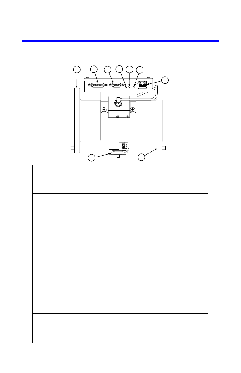
Figure 1 BPM-E Components
Item
(Fig. 1)
Function Description
1 RF Input Input to BPM-E from transmitter
2 Power/Alarm
Parallel Port
Connects to the 3129 digital display using a
15 pin cable.
Note: Also used for remote
operation.
3 RS-232 Serial
Port
4 Alarm LED Red LED, lights when an alarm is triggered
5 Monitor On
LED
6 Reset Switch Press to reset the alarm. If an alarm trigger
7 Ethernet Port Connects to a network or PC ethernet card
8 RF Output Output from BPM-E to antenna or load
9 RF Test Port Insert a sampling element with an
Connects to a 3129 digital display, a PC, or
other display panel using a 9 pin RS-232
cable
Green LED, lights when the unit is powered
is still present, the alarm will reactivate
appropriate connector to connect to a
monitor device (e.g. spectrum analyzer,
modulation monitor, oscilloscope)
3
Page 20
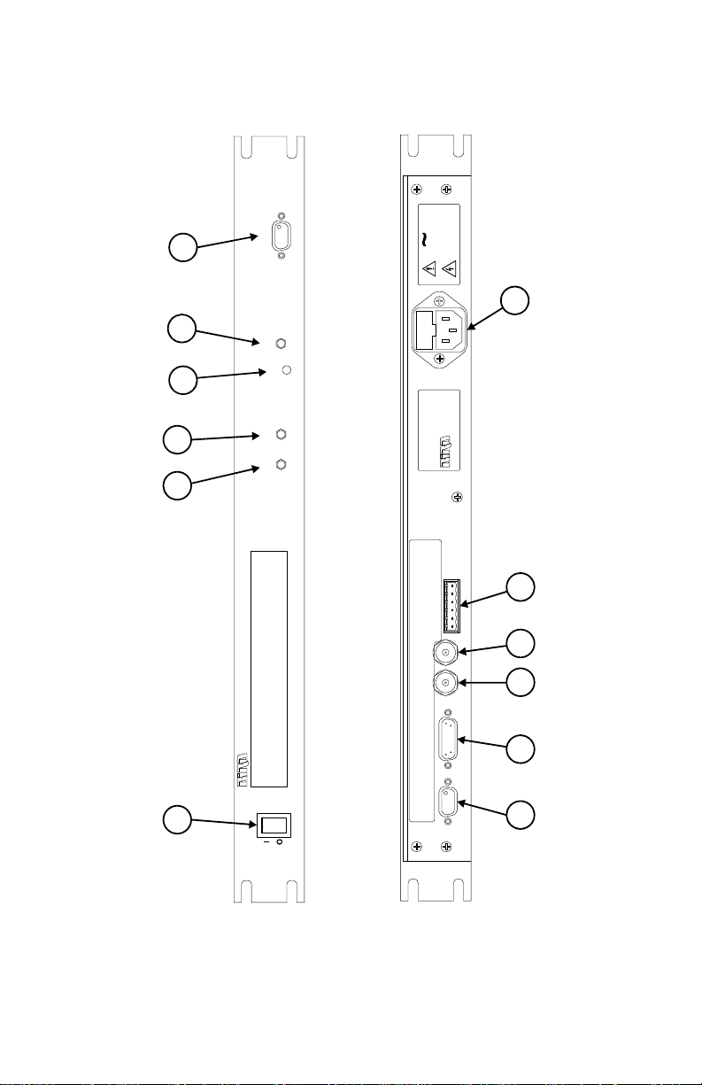
Figure 2 3129 Digital Display Components
Electronic Corporation
Model 3129
True Average Power
Mode Units
Alarm
Reset
Remote
Cleveland, Ohio USA
Phone: (440) 248-1200
www.bird-electronic.com
MODEL 3129
S/N
Electronic Corporation
FUSE 1.0A, 250 V
115/230 VAC
50/60 Hz
.6A MAX.
LINE
C
L
O
S
E
D
N
O
A
L
R
M
O
P
E
N
N
O
A
L
R
M
C
O
M
M
O
N
F
O
R
A
L
R
M
A
L
R
M
T
T
L
O
U
T
R
E
M
O
T
E
R
E
S
E
T
G
R
O
U
N
D
RFL
ANALOG OUTPUT
FWD
POWER/ALARM
SENSOR INTERFACE
RS-232
1
2
3
4
5
6
7
8
9
10
11
12
4
Page 21

Item
(Fig. 2)
Function Description
1 AC Power
Connector
2 Alarm
Interlocks
3 Analog
Output,
Forward
Power
4 Analog
Output,
Reflected
Power
5 Power/
Alarm Port
6 RS-232
Serial Port
7 AC Power
Switch
8 Mode
Button
Connect to ac power supply with a
power cord
Alarm interlocks are used to shut down
transmitter when an alarm condition
occurs. Remote reset can be used to
reset the BPM-E after the alarm event
0 to 2 V full scale, linear, 200 ohm
output impedance, BNC (f) connector
0 to 2 V full scale, linear, 200 ohm
output impedance, BNC (f) connector
Connects to the BPM-E using a 15 pin
cable. Provides operating power to the
BPM-E. Contains analog and digital
alarm information.
Connects to the BPM-E using a 9 pin
RS-232 cable (ASCII data between
the BPM-E and the display)
Turns on the display panel (and BPME if connected).
Selects display mode for the right
field.
9 Units Button Selects the displayed power units.
10 Alarm LED Red LED, lights when an alarm is
triggered
11 Reset
Switch
Press to reset the alarm. If an alarm
trigger is still present, the alarm will
reactivate
12 Remote
Computer
Interface with a PC using a 9 pin RS232 cable
Connector
5
Page 22

6
Page 23

Chapter 2 Theory of Operation
Detector Board
Control
Board
Alarm
LED
Power
LED
Reset
Button
DB-9
Connector
DB-15
Connector
Rj45
Connector
and Xport
Ethernet
Controller
Forward
Coupler
Reflected
Coupler
RF IN
RF OUT
Line Section
General Theory
The enhanced Broadcast Power Monitor (BPM-E) is an instrument that is
inserted directly into a transmission line to monitor the forward power, reflected
power, and VSWR of the system. The BPM-E consists of a line section with forward and reflected directional couplers and an additional housing that contains
the external circuitry. The external circuitry consists of a detector circuit and a
control circuit (Figure 3, page 7).
The directional couplers sample, through a known coupling factor, the forward
and reflected wave in the transmission line. The coupled RF signal is passed to the
detector board and converted into a dc voltage. The dc voltage, which is proportional to the RF power in the line seciton, is then sent to the control circuit.
In the control circuit, an analog-to-digital converter digitizes the incoming signal
and passes it to a micro controller that manages input and output processing.
The control circuitry comminicates by sending signals to the alarm and power
LEDs, receiving a user initiated signal from the reset button, and both sending
and receiving signals via the RS-232 connector (DB9), the ethernet connector
(RJ45), and the power/alarm connector (DB15).
Factors that Affect Power Reading Accuracy
Many sources can affect the accuracy of any in-line power reading. These
sources include directivity of the directional couplers, noise in the system, and
the insertion loss of various system components. To more fully understand how
these and other sources cause the power readings to be out of specification,
consult with a Bird Applications Engineer.
Figure 3 BPM-E Functional Block Diagram
7
Page 24

Alarm Response
When an alarm is triggered, the Bird Broadcast Power Monitor turns on the
alarm LEDs, provides a TTL alarm out signal (low = alarm), and deactivates a
form-C dry contact relay. Additionally the BPM-E can latch the alarm condition
and notify up to two persons via email if you have set up this option in the
WebTool software.
Note: The alarm relay defaults to fail safe. That is, the relay is de-
energized when an alarm activates or when power is lost. If you need
to have an alarm relay that energizes on an alarm, contact Bird (see
title page of this manual).
Alarm Reset
After an alarm occurs, you can reset it in the following ways:
•
Press the reset switch on the BPM-E or on the digital display.
•
Apply a TTL logic low signal (0 to 0.8 Vdc) to the reset pin on the Power/
Alarm connector.
•
Use the PCTool software to reset the unit through the RS-232 port.
•
Use the WebTool software to reset the unit through the ethernet port.
Alarm Latching
The alarm defaults to latching operation. In this mode, the alarm will stay active
until reset. In non-latching mode, the alarm will reset automatically about forty
seconds after the trigger condition is corrected. The latching mode can be
changed using the PCTool or the WebTool.
VSWR Alarm
Activating the VSWR also enables all other alarms that have been selected. Conversely, deactivating the VSWR alarm disables all other alarms that have been
selected.
The BPM-E continuously monitors forward and reflected power. From the power
measurements, the VSWR is calculated and compared to the allowed maximum
(default of 1.8 to 1). Based on the results of the comparison, possible actions
include:
•
No alarms are activated if the VSWR is less than the maximum, or if the
VSWR alarm is disabled.
8
Page 25

•
If:
•
The VSWR is equal to or slightly greater than the maximum, addi-
tional measurements are accumulated to determine a trend.
•
Reverse power is increasing, an alarm is triggered.
•
The reverse power is stable, measurements continue until a trend is
established.
An alarm will be set if the VSWR exceeds the maximum for
more than thirty seconds.
•
If the VSWR is much greater than the maximum then an alarm is trig-
gered immediately.
Alarm on Zero Power
When the forward power is very small (< 2.5% of full scale), the measured VSWR
becomes large due to the noise floor of the sensor. Under these conditions, the
VSWR level is meaningless. When the zero power alarm is disabled, the VSWR
will not be monitored at these low powers.
High Power Alarm
When the high power alarm is enabled, the forward power is continuously monitored. The alarm trigger is a percentage of the Monitor’s full scale power, from 0 –
125%. If the forward power is greater than the trigger level, an alarm is triggered.
Low Power Alarm
When the low power alarm is enabled, the forward power is continuously monitored. The alarm trigger is a percentage of the Monitor’s full scale power, from 0 –
125%. If the forward power is less than the trigger level, an alarm is triggered.
9
Page 26

10
Page 27

Chapter 3 Installation
This chapter provides information for preparing the Bird Broadcast Power Monitor for use.
Unpacking and Inspection
1. Carefully inspect the shipping container for signs of damage. If damage is
noticed, do not unpack the unit. Immediately notify the shipping carrier and
Bird Electronic Corporation.
2. If the shipping container is not damaged, unpack the unit. Save the packing
material in case the unit needs to be shipped again.
3. Inspect all of the components for visible signs of damage. Immediately
notify the shipping carrier and Bird Electronic Corporation of equipment
damage or missing parts.
The Bird BPM-E is shipped complete and ready for use upon receipt. After
unpacking and inspecting the unit, it is ready to be installed.
Tools Required
You will need only common hand tools to install the BPM-E and the 3129 Digital
Display (if used).
WARNING
Leaking RF energy is a potential health hazard. Never attempt to connect or
disconnect equipment from the transmission line while RF power is being
applied. Severe burns, electrical shock, or death can occur.
Mounting a BPM-E
Make sure that the LEDs and reset button are accessible, and that the connecting cables have adequate clearance. Mount the BPM-E in the transmission line
between the transmitter and the antenna. “In” or “RF Input” is the signal from
your transmitter. “RF Output” is the signal going to the antenna or load. Follow
the instructions in this section to mount a BPM-E7 (See “BPM-E7” on page 12), a
BPM-E with a flanged connector (See “Flanged Connector” on page 13), or a
BPM-E with an unflanged connector (See “Unflanged Connector” on page 13).
Be sure to connect the BPM-E to the RF line as described.
11
Page 28

WARNING
RF INPUT
RF OUTPUT
High RF voltage and energy is always present in the RF Test Port when the
system is operating. Do not operate the system if the BPM-E RF Test Port is
open. Close the port with a dummy plug or a suitable sampling plug. Failure
to comply may result in severe burns, electrical shock, or death.
CAUTION
BPM-E signal sensing couplers are fixed in place. Do not attempt to remove or
rotate the couplers. They are calibrated and oriented at the factory and are not
designed to be rotated or removed by the end user. Failure to comply may result
in loss of calibration and accuracy, and in permanent damage to the unit.
BPM-E7
The BPM-E uses QC-type quick change connectors. Use 50 ohm coaxial cable
such as RG-218/U or RG-220/U (-17A or -19A), appropriate for the frequency and
power level of operation. Use a cable connector that will mate with both the
transmission line and the BPM-E7. Connect the BPM-E7 to the RF line as shown
in Figure 4, page 12.
Figure 4 BPM-E 7, RF Direction
12
Page 29

Flanged Connector
RF INPUT RF OUTPUT
To connect a flanged unit to a flanged RF transmission line, use an appropriate
coupling kit. Refer to Figure 5, page 13 for RF input and output orientation.
1. Insert the center connector (bullet).
Note: Push the connector until it is fully seated.
2. Connect the coaxial input in a straight line.
Note: Push carefully to close.
3. Insert the bolt sets.
4. Tighten the bolt sets evenly all around to transmission line manufacturer’s
recommended torque.
Note: Use all of the bolts.
Unflanged Connector
To connect an unflanged unit to an unflanged RF line, use an appropriate coupling kit.
1. Insert the center connector (bullet).
Note: 1.Push the connector until it is fully seated.
2. Position the outer sleeve, with clamping bands, over the input connector.
3. Set the transmission line snugly against the coupling stops.
4. Position the clamping bands evenly about 3/4” from the ends of the sleeve.
5. Tighten the clamping bands.
Figure 5 BPM-E Flanged Line Sections, RF Direction
13
Page 30

3129 Digital Display
Cleveland, Ohio USA
Phone: (440) 248-1200
www.bird-electronic.com
MODEL 3129
S/N
Electronic Corporation
FUSE 1.0A, 250 V
115/230 VAC
50/60 Hz
.6A MAX.
LINE
C
L
O
S
E
D
N
O
A
L
R
M
O
P
E
N
N
O
A
L
R
M
C
O
M
M
O
N
F
O
R
A
L
R
M
A
L
R
M
T
T
L
O
U
T
R
E
M
O
T
E
R
E
S
E
T
G
R
O
U
N
D
RFL
ANALOG OUTPUT
FWD
POWER/ALARM
SENSOR INTERFACE
RS-232
OLD LABEL
NEW LABEL
A
L
R
M
N
O
R
M
C
L
S
D
A
L
R
M
N
O
R
M
O
P
E
N
A
L
R
M
C
O
M
M
O
N
A
L
R
M
T
T
L
O
U
T
R
E
M
O
T
E
R
E
S
E
T
G
R
O
U
N
D
C
L
O
S
E
D
N
O
A
L
R
M
O
P
E
N
N
O
A
L
R
M
C
O
M
M
O
N
F
O
R
A
L
R
M
A
L
R
M
T
T
L
O
U
T
R
E
M
O
T
E
R
E
S
E
T
G
R
O
U
N
D
1 2 3 4 5 6
Note: When using with a BPME, it is recommended to connect the
3129 directly to a universal power source (UPS).
Mounting a 3129 Digital Display
Install the digital display in a standard (1U) rack mount.
AC Power Connector
The AC Power connector (Figure 2 on page 4) provides operating power for the
digital display and the BPM-E electronics. The AC power supply cord is also the
line disconnect device for this product. You can use any approved power cord to
connect to the digital display, such as domestic type SVT, 300 VAC, 18 AWG, 10
A, 3 conductor (including ground) or international type H05VV-F, 300 VAC, 1.00
mm, 10 A, 3 conductor (including ground).
Alarm Interlocks
When an alarm occurs, the 3129 Digital Display utilizes one of the follwing two
methods to shut down your system.
•
A TTL signal (Alarm TTL Out) that goes low on alarm
•
A relay (alarm relay) that de-energizes on alarm
The alarm interlocks are available at the alarm interlock connector at the rear of
the unit (Figure 6, page 14).
Note: The alarm relay label text has been revised for clarity. If you
are connecting to an older Bird 3129 display, the alarm interlock connector might have the “old label” text.
Figure 6 Alarm Interlock Connections
14
1
Page 31

Pin #
(Fig. 6)
1 Ground
2 Remote Reset (reset TTL alarm signal, TTL low = reset)
3 Alrm TTL Out (low = alarm)
4 Common for Alrm (relay contact common)
5 Open No Alrm (relay energized, contacts are open when no
alarm exists)
6 Closed No Alrm (relay energized, contacts are closed when
no alarm exists)
New Label Text and Description
Remote Computer Connector
To communicate with a BPM-E that is connected to the RS-232 port at the rear
of the 3129 Digital Display, connect a PC to the Remote Computer connector on
the front panel of the display. When connected in this manner, signals are
routed directly from the BPM-E through the display to the PC.
To setup a BPM-E connected to the Remote Computer connector (as described
above), follow the setup instructions for RS-232 and PC Tool software in "Setting
Up the BPM-E" on page 19.
Power/Alarm Connector
The Power/Alarm connector provides operating power to the BPM-E and receives
signals and data from the BPM-E. Pin numbers and descriptions are given in
Figure 7, page 16 and a typical connection is illustrated in Figure 8 on page 17.
CAUTION
The DC voltage provided by the 3129 Digital Display power/alarm port should
only be used to power the BPM-E. Do not use the 3129 DC source to supply
power to anything else.
Power ON/OFF Switch
The power switch on the front of the display turns the unit ON or OFF.
15
Page 32

BPM-E DC Power Connections
1
15
8
9
MALE (model ACM-L2-DFDFTL-12SP only)
Connect DC operating power to the BPM-E Power/Alarm 15-pin connector.
The BPM-E requires an isolated +12 to +26 VDC power supply (0.5 A max). This
power is available from the Power/Alarms connector at the rear of the 3129 Digital Display.
If your installation does not use a 3129 Digital Display, you must provide the
required power and connect it to the BPM-E Power/Alarm 15-pin connector. The
BPM-E Power/Alarm connector also provides alarm signals (TTL and relay contacts), a reset line, and forward and reflected power information. See Figure 7,
page 16 for the connector pin descriptions.
Figure 7 DB-15 Power/Alarm Connector
Pin Description
1 Relay , normally closed contact (closed when relay is
not energized)
(open when there is no alarm)
2 Relay, common contact
3 Alarm output, TTL compatible
TTL High (≥ 4.3 VDC with a 10k load) = no alarm
TTL Low (<0.2 VDC) = alarm
4 Forward monitor, 0 to 2 VDC linearly proportional to
forward power, 200 ohm output impedance
5 Reset input, TTL compatible
6-7 No connection
8 Reflected monitor, 0 to 2 VDC linearly proportional
9 Relay, normally open contact (open when relay is
10-11 Reserved
12-13 DC input, +12 to +26 VDC (<0.5 A)
14-15 Ground for DC input and signals
16
TTL Low (<0.5 VDC) resets alarm
to reflected power, 200 ohm output impedance
not energized)
(closed when there is no alarm)
Page 33

BPM-E Data Connections
NETWORK ANALYZER
MODULATION MONITOR
OSCILLOSCOPE
1
2
3 4
5
6
7
8
Cleveland, Ohio USA
Phone: (440) 248-1200
www.bird-electronic.com
MODEL 3129
S/N
Electronic Corporation
FUSE 1.0A, 250 V
115/230 VAC
50/60 Hz
.6A MAX.
LINE
C
L
O
S
E
D
N
O
A
L
R
M
O
P
E
N
N
O
A
L
R
M
C
O
M
M
O
N
F
O
R
A
L
R
M
A
L
R
M
T
T
L
O
U
T
R
E
M
O
T
E
R
E
S
E
T
G
R
O
U
N
D
RFL
ANALOG OUTPUT
FWD
POWER/ALARM
SENSOR INTERFACE
RS-232
The BPM-E has an RS-232 connector and an ethernet connector. The RS-232 connector conducts ASCII data between the BPM-E and a display panel or a PC. The
ethernet connector conducts data between the BPM-E and a network device (hub,
router, PC with network capability). Figure 8 on page 17 shows how a BPM-E can
be connected to a Bird 3129 Digital Display. RS-232 pin numbers and descriptions
are given in Figure 10 on page 18. When you connect using the RS-233 port, you
will use the PCTool software utility to communicate with the BPM-E.
If you connect the BPM-E to the rear panel of a 3129 Digital Display (RS-232 connection), you can also connect a PC to the RS-232 connector on the front of the
display (Remote connector) to communicate with the BPM-E.
The ethernet connector provides a means for you to connect the BPM-E to a
network or directly to a computer with ethernet capability that is not connected
to a network. When you use the ethernet capability, you will also use the WebTool utility to set the IP address, configure the BPM-E, and monitor the power
and alarm status of the transmission line.
Figure 8 BPM-E Rear Panel Data Connections
Item Description
1 3129 Digital Display, rear panel
2 RS-232 communication port, 9-pin
3 Power/Alarm connector, 15-pin
4 Ethernet connector (for network or local PC)
5 Computer (for network or local PC)
6 Sampler port
7 Monitor device (network analyzer, modulation monitor,
oscilloscope)
8 BPM-E controller
17
Page 34

Figure 9 BPM-E Front Panel Data Connections
1
2
3
Electronic Corporation
Model 3129
True Average Power
Mode Units
Alarm
Reset
Remote
Item Description
1 3129 Digital Display, front panel
2 3129 Remote computer connector
3 Computer (PC)
Figure 10 DB-9 RS-232 Connector
Pin Description
1 Carrier Detect, always > +5 C
2 Transmit Output, RS-232 data signal
3 Receive Input, RS-232 data signal
4 Data Set Ready Input, connected but not used
5 Data Signal Ground
6 Data Terminal Ready Output, connected but not
used
7 Clear-To-Send, shorted internally to Ready-T o-Send
8 Ready-To-Send, shorted internally to Clear-To-Send
18
9 Ring Indicator, no connection
Page 35

Setting Up the BPM-E
Note: It is recommended to connec the BPME directly to a universal
power source (UPS).
If you connect directly to a display instead of a computer or network, you can begin
using the BPM-E, as shipped, with the factory default alarm and frequency settings.
However, you should change the settings (frequency, alarms, etc.) to fit your application. To make changes to any of the settings or to set up the BPM-E to communicate
with a computer, you need to use either the PCTool (used with RS-232 connection)
or the WebTool and the Finder utility (used with ethernet connection).
Note: To use the PCTool software or the WebTool software, your PC
must have the Java runtime environment (java virtual machine
v1.4.2 or later) installed prior to connecting the BPM-E. If you do not
have the runtime environment, you can find it on the CD that came
with your BPM-E or you can download it from the web at
www.java.com or from the Bird Technology web site (www.bird-electronic.com). For information about downloading the Java Runtime
Environment, refer to the readme.txt file that was provided on the
CD shipped with your unit.
Installing PCTool and Finder
WARNING
Dangerous RF voltage. Do not connect or apply an RF signal to the BPM-E
during equipment setup. Failure to comply may result in severe burns, loss of
use of limbs, or death.
1. Make sure that there is NO RF power applied to the BPM-E.
2. Copy the file named SETUP.EXE from the CD that came with your unit to a
temporary folder on your hard drive. You can also download SETUP.EXE
from the Bird Technology web site (www.bird-electronic.com).
3. Launch SETUP.EXE from your hard drive. Typically if you double-click the file
name, the file will launch.
4. Follow the on-screen instructions to complete the installation. When the
installation is complete, you will see the PCTool main screen with no data in
the fields (Figure 11, page 20).
Note: IF you have an older version of PCTool installed on your
computer, the installation process in this step will uninstall the
older version. To install the newer version, you must run SETUP.EXE
a second time.
19
Page 36

Figure 11 PCTool Installation Screen
5. Do one of the following to set up your BPM-E:
•
If you connect your BPM-E directly to a display panel (such as the Bird
2139 Digital Display) using an RS-232 cable, or you connect it directly
to a PC using an RS-232 cabl, follow the setup instructions described in
See “Connecting the BPM-E Using the RS-232 Port” on page 20.
•
If you connect your BPM-E directly to a PC or to a network using an
ethernet cable, follow the setup instructions described in See “Con-
necting the BPM-E Using the Ethernet Port” on page 22.
Connecting the BPM-E Using the RS-232 Port
The RS-232 communication protocol is fixed in the firmware and cannot be modified.
1. Connect the computer’s serial port, via a DB-9 cable, directly to the BPM-E
or to the BPM-E through a 3129 digital display.
Note: Do not use a null modem adapter.
2. Install the Java runtime environment, refer to "Setting Up the BPM-E" on
page 19.
Note: Perform this step if it is not already done.
20
Page 37

WARNING
Dangerous RF voltage. Do not connect or apply an RF signal to the BPM-E
during equipment setup. Failure to comply may result in severe burns, loss of
use of limbs, or death.
WARNING
Do not connect RF power to the unit.
3. Apply operating power to the BPM-E. Refer to "BPM-E Data Connections"
on page 17).
4. Launch PCTool from your hard drive.
5. Specify which COM (serial) port the BPM-E will use:
a. On the Menu bar, click on Connection and select New....
b. On the New Connection dialog box, select the computer
COM port to which the BPM-E is connected then click OK
(Figure 12, page 21).
Note: When the BPM-E establishes communication with your PC, the
PCTool software will display the COM port being used in the space
immediately below the Menu bar.
Note: To use the features of the PCTool software, refer to
Chapter 4 Operating Instructions on page 27.
Figure 12 PCTool, Select a COM Port
21
Page 38

Connecting the BPM-E Using the Ethernet Port
When you connect to the BPM-E using the ethernet port, you use the WebTool
software to setup the BPM-E. You do not need to install the WebTool software
because it is part of the BPM-E firmware.
Note: You must have Java runtime installed before you can use the
WebTool software.
CAUTION
Network connections require specific address and protocol information. Have a
qualified IT or network professional perform the BPM-E ethernet setup. Failure to
comply may result in loss of network communication or the inability to
communicate with the BPM-E.
The setup in this section should be performed only by a person who thoroughly
understands IP and network setup protocols.
Note: If you are connecting to a network, before you begin, do the
following:
•
Contact your IT professional to get the subnet mask values for
your network and to determine whether or not your network
has a DHCP server.
•
Inform your network administrator that the BPM-E will use port
10001. The network administrator might need to open this
port before you can set up the BPM-E.
1. Install the Java runtime environment (refer to See “Setting Up the BPM-E”
on page 19).
Note: Perform this step if it is not already done.
Note: To use the WebTool software, your PC must have the Java run-
time environment (java virtual machine v1.4.2 or later) installed prior to
connecting the BPM-E to an ethernet device. If you do not have the runtime environment, you can download it from the web at www.java.com
or from the Bird Technology web site (www.bird-electronic.com). For
information about downloading the Java 2 Runtime Environment, refer
to the readme.txt file that was provided with your unit.
WARNING
Dangerous RF voltage. Do not connect or apply an RF signal to the BPM-E
during equipment setup. Failure to comply may result in severe burns, loss of
use of limbs, or death.
WARNING
Do not connect RF power to the unit.
2. Apply operating power to the BPM-E, refer to "BPM-E Data Connections" on
page 17).
3. Follow the ethernet setup flowchart (Figure 13, page 23) to complete the
installation.
22
Page 39

Figure 13 Ethernet Connection Flowchart
Change your computer
IP to 169.254.x.x and
subnet to 255.255.0.0
Record the IP and subnet
address of your computer
Use a cross-over Ethernet
cable to connect BPM-E
to computer
Start the BPMFinder utility
on your computer and
enter the subnet mask
of your network
Does your
network have a
DHCP server?
Connect BPM-E to
network with a standard
Ethernet cable
Will you
connect directly
to the BPM-E
for setup?
Record the BPM-E
serial number
YES
YES
NO
NO
1. Start the BPMEFinder utility
on your computer
2. Enter the subnet mask
as 255.255.0.0
3. Click the button Find BPMEs
On Network
4. On the BPMEFinder list, click
on the serial number that
matches your unit
A
0
153363
CH 17 XMTR
SITE 7A
Note: The name you enter (at the left of the @ symbol) is also used in
the BPM-E Finder utility. If you use the email option to notify someone
that an alarm has occurred, the name of this BPM-E will help identify
where the alarm came from.
23
Page 40

When you click on the serial
number that matches your unit,
the WebTool starts. If WebTool
doesn’t start, your web browser
is not in your path. Either add it
to your path or open your Web
browser and enter the IP address
of the BPM-E in the address bar.
http://<ip address>
A
B
Click on ‘Email Alerts’ tab and check
the ‘Enabled’ box.
Fill out ‘Email From’ field to set the
BPM-E’s name on the network (or
leave it as is to identify the BPM-E
it by serial number).
Uncheck the ‘Enabled’ box to disable
email alerts.
OR
Leave the ‘Enabled’ box checked and
fill out the ‘Email Recipient’ fields
and SMTP server IP address.
E
D
24
Page 41

If you access the BPM-E
using a static IP or Host
name, you can save the
webpage address in your
Favorites (a dynamic IP
may be different each time
the BPM-E connects).
When BPM-E is attached to its final
destination network or computer,
connect to it either by typing its IP
address or host name in the address
bar of your web browser, or use the
BPMEFinder with your network or
computer’s subnet mask to find and
connect to the BPME.
If computer IP address or
subnet mask were changed,
restore the original settings.
Click ‘Apply all Changes’
Setup is now
complete
E
Note: To use the features of the WebTool software, refer to
Chapter 4 Operating Instructions on page 27.
25
Page 42

26
Page 43

Chapter 4 Operating Instructions
This chapter provides a description of controls and indicators on the BPM-E and
the 3129 Digital Display. Read and become familiar with the following instructions before operating the unit.
Couplers
The BPM-E does not use elements to sense the RF signal. It uses couplers. The
couplers are fixed in place.
CAUTION
BPM-E signal sensing couplers are fixed in place. Do not attempt to remove or
rotate the couplers. They are calibrated and oriented at the factory and are
not designed to be rotated or removed by the end user. Failure to comply may
result in loss of calibration and accuracy, and in permanent damage to the
unit.
BPM-E Controls
There are two indicators and one control on the BPM-E:
Monitor On LED (green) - Lights when the unit is powered.
Alarm LED (red) - Lights when an alarm has been triggered.
Reset Switch - Press to reset an alarm. If the alarm trigger condition is still
present, the alarm will reactivate.
3129 Digital Display
Power On
After the AC power switch is set to ON, a message will be displayed. Examples of
possible messages are:
•
‘Digital display ver x.xxx’ Shown at power-up for about 4 seconds.
•
‘Waiting...’ Shown when no response is received from the BPM-E.
•
‘Serial Pass Thru...’ Shown when a PC or other remote device is connected
to the Remote Computer Connector on the front panel.
27
Page 44

Mode Button
Press MODE to cycle through the possible display modes for the right half of the
display, which are:
•
Reflected Power
•
Match Efficiency (%)
•
Return Loss (dB)
•
VSWR (SWR)
•
Reflection Coefficient (ρ)
Units Button
Press UNITS to toggle the display between Watts (W or kW) and dBm. The unit applies
to forward power and to reflected power (if it is displayed).
Reset Button
Resets the alarm LED if the alarm condition is no longer present. Directly connected to
the Reset Input pin of the BPM-E Power/Alarm connector.
Alarm LED
Indicates the presence of an alarm condition. Directly connected to the Alarm
pin on the BPM-E Power/Alarm connector.
WebTool Software
The BPM-E WebTool software is used to monitor the measurement outputs from
the BPM-E and to set and change alarm and network configurations. This software runs in a web browser (such as Microsoft’s Internet Explorer). To use the
tool, open a web browser then in the address field, type the address of the
BPM-E you wish to access. The software has five buttons at the left side that
open the following screens: Main, Stats, Config, Admin, and Help. You can access
information about the WebTool software by click on the Help button.
28
Page 45

Main Screen
The Main screen is the default screen you see when you open the WebTool software (Figure 14, page 29). The Main screen identifies the BPM-E at the top of
the window. The center of the screen displays measurement data that is being
received from the BPM-E. You can set the refresh rate from 1 second to 60 seconds (how frequently the software updates the data from the BPM-E). At the
bottom of the window, the status bar displays various information about the
software and uses three alert colors, red - a fatal error (cannot establish connection, connection lost), yellow - a warning (cannot complete a user request, user
does not have access permission), gray - normal operation.
For more information about the Main screen features, refer to the help section
in the software (click on the Help button).
The alarm condition area (Figure 15, page 30) will display three conditions
•
No alarm (green text) - no alarm condition exists
•
Latched (red text) - an alarm condition did occur but its cause has been
fixed or the cause no longer exists.
•
Alarm (red text) - an alarm condition that has occurred and has not
gone away or been reset is identified by text (VSWR, High Pwr, Low Pwr,
or any combination of these if more than one alarm exists).
You can reset the alarm at the BPM-E by pressing the reset button or by clicking
on the Reset Alarm button on the Web Tool Main screen. If the cause of the
alarm is still present, the message cannot be reset.
Figure 14 BPM-E WebTool Software, Main Screen
29
Page 46

Figure 15 Alarm Active Message
Reset Alarm
Stats Screen
The Stats screen (Figure 16 on page 30) can chart and display historical data
stored in the BPM-E memory. You can chart forward and reflected power readings and alarm conditions (low power, high power, and VSWR alarm). You can
display the data in either a line graph or a bar chart.
The BPM-E keeps data for a 365 day period. You select the starting day (in the
Begin field) and the number of days to view. Day 0 is today, day 1 is yesterday,
and so on to day 364. Click the Add >> button to add the days to the list to view.
When you click the Chart It button, the WebTool retrieves the data and generates a new chart. Click the Clear button to clear your day selection.
For more information about the Stats screen features, refer to the help section
in the software (click on the Help button).
Figure 16 Web Tool Stats Screen
30
Page 47

Config Screen
The Config (Configure) screen has two tab views, Alarms and Frequency. The
administrator of the WebTool can set an optional password requirement to control who can make changes to the Config screen (refer to Admin Screen for password control).
For more information about the Config screen, refer to the help section in the
software (click on the Help button).
Alarm Tab
In the Alarms tab (Figure 17, page 32), you specify BPM-E alarm settings. To
return to the factory default alarm settings, click on the Factory Default button.
After you have set the alarm preferences, click the Apply Changes button to
record your settings in memory.
You can select or deselect the following alarm conditions:
Master Alarm Enable - When checked, activates the VSWR alarm and
enables all other alarm conditions that have been selected (boxes checked), disables all alarms when not checked.
VSWR trip point - Specify the VSWR value that will cause an alarm (select val-
ues from the drop-down list). This value is adjustable from 1.3 to 2.5 by increments of 0.1. Check the VSWR Alarm Enabled on Zero Power checkbox to allow
the VSWR alarm to trigger at very low forward power (< 2.5% of full scale
power). Refer to See “Determining VSWR Alarm Trip Point” on page 53 for additional information about limitations of the VSWR trip point.
High Power Alarm (forward power only) - Check the Enable box and spec-
ify the percentage of full scale at which an alarm will occur. The high power
value must be greater than the low power value. The maximum value is 125% of
full scale power. The alarm setpoint is entered as a percent of full scale. For
example, if you have a 500W full scale unit and would like an alarm when the
forward power exceeds 375 W, the alarm setpoint would be 375/500 x 100 or
75%. Enter 75 in the field and check the Enable High Power Alarm checkbox.
Low Power Alarm (forward power only) - Check the Enable box and spec-
ify the percentage of full scale at which an alarm will occur. The low power value
must be less than the high power value. The minimum is 0%.
Latch Alarms - Sets whether the alarm will reset automatically in the absence
of an alarm condition. When this checkbox is unchecked, if an alarm trigger is
corrected, the alarm will reset after a forty-five second delay. When the box is
checked, the alarm must be manually reset.
Trigger Alarm Button - After you have set or made changes to alarm settings,
you can use the Trigger Alarm button to test the alarms (messages, relay, TTL outputs). If the Config password is enabled, you will be required to enter the password
before you can test the alarm settings.
31
Page 48

Figure 17 WebTool Config Screen, Alarms
Frequency Tab
In the Frequency view (Figure 18 on page 32), you specify monitor frequencies
and then apply that configuration to the BPM-E. Click the View Channel List button
to display a list of United States television channels and their frequencies (Figure ,
page 32). To add a frequency to the Selected Frequencies list, type it in the Frequency (MHz) field, then click the Add button. To remove a frequency from the
list, click on the frequency to select it, then click on the Remove button. After you
have set the configuration frequencies, click the Configure button to record your
settings to memory. The value shown beside Configuration Frequency is the center frequency of all of the values in the Selected Frequencies list.
Note: The changed frequencies stored in memory will not take effect
until the BPM-E power has been turned off and then back on.
Figure 18 Web Tool Config Screen, Frequency
32
Page 49

Admin Screen
The Admin screen has four tabs, Network, Email Alerts, SNMP, and Passwords.
After making changes in one or all of the tabs, click the Apply All Changes button
to record your settings in memory.
For more information about the Admin screen, refer to the help in the software
(click on the Help button).
Network Tab
In the Networking tab (Figure 19 on page 33), you can specify the following information about the address of the BPM-E: IP address, subnet mask, gateway IP,
DHCP host name, and whether or not DHCP is used.
If you use the ethernet connection to communicate with the BPM-E, you need to
specify a unique IP address. An IP address is required even if you connect the
BPM-E directly to a computer that is not on a network. Contact your IT professional for assistance in determining the IP address, subnet mask, and information
about DHCP use and name.
Figure 19 WebTool Admin Screen, Network Setup
Email Alerts Tab
In the Email Alerts tab (Figure 20 on page 34), you can specify the following information: the SMTP server IP, the SMTP port, whether or not to use the email alerts,
the email address of the BPM-E, and the email addresses of two people to notify
when an alarm occurs (optional).
You can have the WebTool software contact two specified recipients via email if
an alarm occurs. The BPM-E needs to be connected to a computer or server that
has email capabilities. Contact your IT professional for assistance in determining
the SMTP server IP and port. The text you enter at the left of the @ symbol in
the From email address will uniquely identify this BPM-E in all sent emails. Use
text that will identify the BPM-E and its location. The text at the right of the @
symbol is the email domain information for your server.
33
Page 50

Figure 20 WebTool Admin Screen, Email Alerts
SNMP Tab
In the SNMP tab (Figure 21 on page 34), you can specify setup for the SNMP feature if you have chosen to use it. Contact your IT professional for assistance. You
can obtain the latest MIB file from the Bird Technologies web site.
Figure 21 WebTool Admin Screen, Set SNMP Email Address
34
Page 51

Password Tab
In the Password tab (Figure 22 on page 35), you can set the administrator password and the optional configuration access password. When you set or change a
password, you must type the password a second time in the appropriate “confirm”
field before it will be accepted.
You must have a password to view and edit the Admin screen. The default password is “bird” (lower case without the quotes). After you make changes, click on
the Apply All button.
If a configuration access password is set, users can view the Config screen but
not edit it. A password must have at least 3 and no more than 49 characters.
Figure 22 Web Tool Admin Screen, Passwords
Help Screen
While you are using the WebTool software, you can get help about the screens
and features by clicking on the Help button at the left side of the screen.
35
Page 52

PCTool Software
The BPM-E PCTool software is used to monitor the measurement outputs from the
BPM-E and to set and change alarm configurations. This software is a stand-alone
application that must be installed onto your PC. To use the tool, launch it from the
computer’s operating system menus or from a shortcut on your desktop.
Note: Your PC must have the Java runtime environment (java vir-
tual machine) installed to run the PCTool software. For Windows
operating systems, this is typically installed by default. If you do not
have the runtime environment, you can download it from the
java.com web site (look for Java Software for Desktop).
The PCTool screen (Figure 23, page 36) is divided into three parts, the Menu bar
at the top, the information area in the center, and the status bar at the bottom.
The BPM-E identification and the COM port being used appear in the space
immediately below the Menu bar. The status bar displays various information
about the software and uses three alert colors, red - a fatal error (cannot establish connection, connection lost), yellow - a warning (cannot complete a user
request), gray - normal operation. The Menu bar has the following four entries:
File - Contains the command to exit the software
Connection - Contains two options, New (select a COM port), and Close (dis-
connect the BPM-E from the PC)
View - Contains two options, Main (open the Main screen) and Config (open
the Config and Alarm screen)
Help - Provides information about the software version and opens the on-line
help screens.
Figure 23 PCTool Screen, Main Screen
36
Page 53

Connection
The PCTool software must be set to use the correct computer COM port to communicate with the BPM-E. The default port is COM 1. To change the Com port,
select Connection from the Menu bar, then select New. Choose the COM port
you want from the drop-down list in the dialog box then click OK (Figure 24,
page 37).
Note: The Connection menu also has a Close command. Choosing
the Close command will close (break) the COM port connection to the
computer.
For more information about the Connection screen features, refer to the help
section in the software (click on Help on the Menu bar).
Figure 24 PCTool Software, New Co nnection Com Menu
View
The View menu has two options, Main and Config.
Main
The “Main” screen (Figure 23, page 36) is the default screen you see when you
open the PCTool software. It displays forward and reflected power, VSWR, return
loss, Rho, efficiency, and alarm conditions.
37
Page 54

The alarm condition area displays information in three colors:
No alarm (green text) - No alarm condition exists
Latched (red text) - An alarm has happened, but has cleared
Alarm (red text) - An alarm has happened and is identified (VSWR, High Pwr,
Low Pwr, or any combination of these if more than one alarm exists)
If an alarm has occurred and has not been reset, the alarm text will be red and
will display which alarm (or alarms) occurred (Figure 25, page 38). You can reset
the alarm at the BPM-E or by clicking on the Reset Alarm button on the Main
screen. If the alarm condition is still present, the message cannot be reset.
You can also set the refresh rate from 1 second to 60 seconds (how frequently
the software updates the data from the BPM-E).
For more information about the Main screen features, refer to the help section
in the software (click on Help on the Menu bar).
Figure 25 PCTool Main Screen (alarm display)
Config
The Configure (Config) screen has two tab views, Alarms and Frequency.
Alarm Tab - In the Alarms tab (Figure 26, page 39), you specify BPM-E alarm set-
tings. To return to the factory default alarm settings, click on the Factory Default
button. After you have set the alarm preferences, click the Apply Changes button
to record your settings in memory.
38
Page 55

Figure 26 Config Screen, Alarm Tab
You can select or deselect the following alarm conditions:
Master Alarm Enable - When checked, activates the VSWR alarm and
enables all other alarm conditions that have been selected (boxes checked), disables all alarms when not checked.
VSWR trip point - Specify the VSWR value that will cause an alarm (select val-
ues from the drop-down list). This value is adjustable from 1.3 to 2.5 by increments of 0.1. Check the VSWR Alarm Enabled on Zero Power checkbox to allow
the VSWR alarm to trigger at very low forward power (< 2.5% of full scale
power).
High Power Alarm (forward power only) - Check the Enable box and spec-
ify the percentage of full scale at which an alarm will trigger. The high power
value must be greater than the low power value. The maximum value is 125% of
full scale power. The alarm setpoint is entered as a percent of full scale. For
example, if you have a 500W full scale unit and would like an alarm when the
forward power exceeds 375 W, the alarm setpoint would be 375/500 x 100 or
75%. Enter 75 in the field and check the Enable High Power Alarm checkbox.
Low Power Alarm (forward power only) - Check the Enable box and specify
the percentage of full scale at which an alarm will trigger. The low power value must be
less than the high power value. The minimum is 0%.
Latch Alarms - Sets whether the alarm will reset automatically in the absence
of an alarm condition. When this checkbox is unchecked, if an alarm trigger is
corrected, the alarm will reset after a forty-five second delay. When the box is
checked, the alarm must be manually reset.
After you have set or made changes to alarm settings, you can test the settings
by clicking on the Trigger Alarm button.
39
Page 56

Frequency Tab
In the Frequency tab (Figure 27 on page 40), you specify monitor frequencies and
then apply that configuration the BPM-E. Click the View Channel List button to display a list of United States television channels and their frequencies (Figure 28,
page 40). To add a frequency to the Selected Frequencies list, type it in the Frequency (MHz) field, then click the Add button. To remove a frequency from the
list, click on the frequency to select it, then click on the Remove button. After you
have set the configuration frequencies, click the Configure button to record your
settings to memory. The value shown beside Configuration Frequency is the center frequency of all of the values in the Selected Frequencies list.
Figure 27 Config Screen, Frequency Tab
Figure 28 US Television Channel List
40
Page 57

Chapter 5 Maintenance
This chapter contains cleaning, troubleshooting, specifications, and part information for the Bird Broadcast Power Monitor and the 3129 Digital Display.
Inspection and Cleaning
This unit requires only simple and routine maintenance.
WARNING
Disconnect the unit from the RF power source and the ac
line before any disassembly. The potential for electrical
shock exists.
CAUTION
Do not use harsh or abrasive detergents for cleaning.
1. Wipe off dust and dirt regularly. Use a soft, clean cloth dampened with mild
detergent.
2. Check connectors, connector pins, and cables for damage. If needed, clean
the connectors using a self-drying contact cleaner that leaves no residue.
3129 Digital Display Fuses
The 3129 Digital Display contains two time-delayed IEC (5 x 20mm) Type T 1.0A,
250V fuses. These are the only user replaceable parts. Refer to figure Figure 29
on page 42 for fuse location.
41
Page 58

Figure 29 3129 Digital Display, Fuse Location
1
2
3
Item Description
1 Fuse holder tab, pry outward to remove fuse holder
2 Fuse holder
3Fuse
Specifications
BPM-E Specifications
Frequency Range
VHF low
VHF
UHF
Dynamic Range, Min 20 dB
Max Allowable Peak/
Average Ratio
Insertion Loss, Max 0.05 dB
Directivity, Min 26 dB min, 30 dB typical
42
45 – 88 MHz
88 - 230 MHz
470-890 MHz
10 dB min. at max RF power
Page 59

Detection Method T rue Average Power
Impedance 50 ohms
Accuracy
Power
Calibrated for FM band
TV Channels 1-6
TV Channels 7-83
VSWR
Display Resolution
RMS Noise
Connectors, RF See See “Line Section Sizes” on
RS-232 Serial Port
Connector
Protocol
DC Power Required
Analog Outputs
NOTE: Refer to See “Factors that Affect
Power Reading Accuracy” on page 7 in
the Theory of Operation to learn about
factors that can cause power readings to
be out of spec.
± 5% of reading
± 5% of reading at calibrated channel ± 1
channel
± 5% of reading at calibrated channel ± 4
channels
Calculated from Fwd and Rfl power
± 1 digit
0.1 % of full scale
page 49
Female DB-9
9600 baud, no parity, 8 data bits, 1 stop
bit, no handshake
+12 to +26 Vdc @ <0.5A
2V full scale, 0 to 2V range, 200 ohm
output impedance, linear scale.
Ethernet port
Network Interlace
Compatibility Protocols
Left LED
Right LED
Security
Power/Alarm Parallel Port
Display Options
Ethernet 10/100 BASE-T (auto sensing)
Ethernet version 2.0 / IEEE 802.3
ARP, UDP/IP, TCP/IP, DHCP, BOOTP,
AutoIP, and HTTP
Amber: 10 Mbps. Green: 100 Mbps
Amber: Half-duplex. Green: Full-duplex
128 bit encryption
Female DB-15 connector
BPM-E-PCTool, 3129 digital display,
Site Analyzer, BPM-E-WebTool
43
Page 60

Alarm
Alarm Relay
Relay Contact Rating
VSWR set points
Alarm Stimulus
Alarm Response
Alarm Reset
Alarm Power Up
Environmental
Operating Temp
Storage Temp
Humidity
Altitude
CE CE compliant
Calibration Cycle > 1 year
Dry, contacts, with common, normally
open, and normally closed connections
(form C)
100 Vdc @ 0.5 A
1.3 to 2.5:1 by 0.1 steps, measurement
limited by max input power
VSWR, high forward power, low forward
power
Turn on red LED; trip relay; set software
flag; set alarm line low (<0.2V); Send email
Response time is inversely proportional to
the overload
Push button on BPM-E
Push button on 3129 digital display
Ethernet or RS-232 command TTL low
(Vdc=0 to +0.8 V)
Alarm defaults to fail-safe (alarm on
when unit is not powered
0 to +50 °C (+32 to 122 °F)
–20 to +80 °C (–4 to +176 °F)
95% max. (non-condensing)
3000 m (10,000 ft.) above sea level
Recommended Calibration
Cycle Interval
Dimensions See See “Line Section Sizes” on
Weight, Nominal See Figure 31, page 49
3129 Digital Display Specifications
Display 20 character LCD with LED backlight
RS-232 Serial Port
Connector
Protocol
Power/Alarm Parallel Port Male DB-15 connector
User defined
page 49
Male DB-9
RS-232, 9600 baud, no parity, 8 data bit s,
1 stop bit, no handshake
44
Page 61

Remote Computer Connector
Connector
Protocol
AC Power Requirements 115/230 Vac @ 50/60 Hz, 0.6 A
AC Connector
Domestic
International
T emperature
Operating
Storage
Humidity 95% max. (non-condensing)
Altitude 3000 m (10,000 ft.)
Dimensions 19" L x 1.75" W x 5" H
Weight, Nominal < 10 lbs
RF Power Range, VHF Frequency Band (45-230 MHz)
Female DB-9
RS-232, 9600 baud, no parity, 8 data bit s,
1 stop bit, no handshake
North American Power Cord Standard
Type SVT, 300 Vac, 18 A WG, 10 A, 3
conductor (including ground)
Type H05VV-F, 300 Vac, 1.00 mm, 10 A,
3 conductor (including ground)
–10 to +50 °C (+14 to 122 °F)
–40 to +80 °C (–40 to +176 °F)
(483 x 44 x 127 mm) (1U EIA)
Line size
7/8” High
1-5/8” High
3-1/8” High
4-1/16” and
4-1/2”
6-1/8” High
Unit power
Med
Low
Med
Low
Med
Low
Extra Low
High
Med
Low
Med
Low
range
Measurable
Range, Fwd
5000 - 50 W
2000 - 20 W
500 - 5 W
20 - 0.2 kW
8000 - 80 W
2000 - 20 W
50 - 0.5kW
20 - 0.2 kW
5000 - 50 W
1000 - 10 W
100 - 1 kW
40 - 0.4 kW
10 - 0.1 kW
200 - 2 kW
80 - 0.8 kW
20 - 0.2 kW
Measurable
Range, Rfl
500 - 5 W
200 - 2 W
50 - 0.5 W
2000 - 20 W
800 - 8 W
200 - 2 W
5000 - 50 W
2000 - 20 W
500 - 5 W
100 - 1 W
10 - 0.1 kW
4000 - 40 W
1000 - 10 W
20 - 0.2 kW
8000 - 80 W
2000 - 20 W
45
Page 62

RF Power Range, UHF Frequency Band (470-890 MHz)
Line size Unit power
range
7/8” High
Med
Low
1-5/8” High
Med
Low
3-1/8” High
Med
Low
Extra Low
4-1/16” and
4-1/2”
6-1/8” High
High
Med
Low
Med
Low
Measurable
Range, Fwd
2500 - 25 W
1000 - 10 W
250 - 2.5 W
5000 - 50 kW
2000 - 20 W
500 - 5 W
25 - 0.25 kW
10 - 0.1 kW
2500 - 25 W
1000 - 10 W
40 - 0.4 kW
15 - 0.15 kW
4000 - 40 W
75 - 0.75 kW
30 - 0.3 kW
8000 - 80 W
Measurable
Range, Rfl
250 - 2.5 W
100 - 1 W
25 - 0.25 W
500 - 5 W
200 - 2 W
50 - .05 W
2500 - 25 W
1000 - 10 W
250 - 2.5 W
100 - 1 W
4000 - 40 W
1500 - 15 W
4000 - 4 W
7500 - 75 W
3000 - 30 W
800 - 8 W
46
Page 63

Troubleshooting
The Bird Broadcast Power Monitor has no operator serviceable parts. Any required
service must be performed at an authorized service facility.
The table below contains troubleshooting information for problems which can
occur during normal operation. This manual cannot list all malfunctions that
may occur or their corrective actions. If a problem is not listed or is not corrected by the listed actions, notify a qualified service center.
PROBLEM POSSIBLE CAUSE CORRECTION
Monitor On LED
does not
illuminate
Alarm LED does
not illuminate
when alarm
exists
High VSWR Dirty connectors Clean connectors
Digital display
screen does not
light
No dc power Check power source, and
15 pin power/alarm cable
Defective LED Return the unit to an
authorized service center
Defective LED Return the unit to an
authorized service center
Defective power/alarm
cable
Defective connectors Replace connectors
Shorted or open
transmission line
Unit is not turned on Set AC Power Switch to
Unit is not plugged in Connect AC power cord
Fuse is blown Replace fuse
Repair or replace cable
Have the line serviced.
ON
Replacement Parts
Description Part Number
Digital Display 3129
9 pin RS-232 Interface Cable
50 ft.
10 ft.
DB-15 Interface Cable,
50 ft., male/female 5A2264-15-MF-50
DB-15 Interface Connector SUBCON-15/M-SH
Fuse, for 3129 digital display (1
amp, slow blow)
5A2264-09-MF-50
5A2264-09-MF-10
5A2257-16
47
Page 64

RF Power Ratings
4
-1/16 ”
&
4-
1
/
2
”
6-1/8 ”
Line Section Max RF Power vs. Frequency
1000
100
10
Max Average Power (kW)
Frequency (Mhz)
10
1
100 1000
3
-1/
8 ”
7
/
8
”
1
-
5
/
8
”
For power ratings based upon line sizes, refer to See “Specifications” on page 42.
Note: For a specific frequency and line size, the maximum safe oper-
ating power may be lower than the full scale power measurement
capability of the BPME.
48
Page 65

Line Section Sizes
6.5”
(165 mm)
6 11/64”
(169.9 mm)
3 1/8”
(79.4 mm)
BPM-E7
4.25”
(106 mm)
C
POWER/ALARM RS/232
ALARM
OPR/TEST
RESET
BROADCAST
POWER MONITOR
Cleveland, Ohio USA
Phone: (440) 248-1200
www.bird-electronic.com
B
A
4.5”
114 mm
()
Figure 30 BMPE Dimensions, Model BPM-E7
Figure 31 BPM-E Dimensions, Flanged and Unflanged Models
49
Page 66

Inner
Conduc
1
Model Connector
BPME1 1-5/8” EIA
Flanged
BPME1U 1-5/8” EIA
BPME1UF 1-5/8” EIA
BPME3 3-1/8” EIA
BPME3U 3-1/8” EIA
BPME3UF 3-1/8” EIA
BPME4AUF 4-1/2” IEC
BPME4D 4-1/16”
BPME4M 4-1/16”
BPME6 6-1/8” EIA
BPME6U 6-1/8” EIA
BPME7 7/8” line,
1
For unflanged units, this dimension is the outer diameter of the transmission line.
Unflanged
Unflanged,
Flush Center
Flanged
Unflanged
Unflanged,
Flush Center
Unflanged
Flanged,
Dielectric
Standard
Flanged,
Myat
Standard
Flanged
Unflanged
Type N
connectors
Dim. A
3.50”
(89 mm)
1-5/8”
(41.3 mm)
1-5/8”
(41.28 mm)
5.19”
(132 mm)
3-1/8”
(79.4 mm)
3-1/8”
(79.4 mm)
4.17”
(106 mm)
6.19”
(157 mm)
6.19”
(157 mm)
8.13”
(206 mm)
6-1/8”
(155.6 mm)
1.25”
(318 mm)
Dim. B Dim. C
6.75”
(171.5 mm)
6.38”
(162 mm)
6.38”
(162 mm)
7.03”
(178.6 mm)
6.5”
(165.1 mm)
6.5”
(165.1 mm)
7.5”
(190.5 mm)
8.38”
(212.8 mm)
8.38”
(212.8 mm)
10.22”
(259.6 mm)
9.63”
(244.6 mm)
n/a n/a n/a 1.25 lbs.
2.98“
(75.7 mm)
2.98“
(75.6 mm)
2.98“
(75.6 mm)
3.4“
(86.4 mm)
3.4“
(86.4 mm)
3.4“
(86.4 mm)
3.96”
(100.7 mm)
3.87“
(98.2 mm)
3.87“
(98.2 mm)
4.96“
(126 mm)
4.96“
(126 mm)
tor
Setback
EIA 3.25 lbs.
0.438”
(11.1 mm)
0 1.5 lbs.
EIA 7.25 lbs.
0.688”
(17.5 mm)
0 4.25 lbs.
0.06”
(1.5 mm)
1.22”
(31 mm)
1.375”
(35 mm)
EIA 17 lbs.
0.968”
(24.6 mm)
Weight
(1.5 kg)
1.5 lbs.
(0.68 kg)
(0.68 kg)
(3.3 kg)
4.25 lbs.
(1.93 kg)
(1.93 kg)
10 lbs.
(4.55 kg)
8.88 lbs.
(4 kg)
8.88 lbs.
(4 kg)
(4 kg)
12.75 lbs.
(5.78 kg)
(0.57 kg)
50
Page 67

3129 Digital Display
Electronic Corporation
Model 3129
True Average Power
Mode Units
Alarm
Reset
Remote
1.75 ”
(44 mm)
0.25 ”
(6 mm)
1/8 ”
(3 mm)
19 ”
(483 mm)
(432 mm)
4.92 ”
(125 mm)
WARNING
SHOCK HAZARD
REMOVE AC POWER BEFORE ATTEMPTING
TO SERVICE THIS INSTRUMENT
Figure 32 3129 Digital Display Dimensions
51
Page 68

Customer Service
Any maintenance or service procedure beyond the scope of those in this chapter
should be referred to a qualified service center.
If you need to return the unit for any reason, request an RMA through the Bird
Technologies website (link shown below). All instruments returned must be
shipped prepaid and to the attention of the RMA number.
Bird Service Center
30303 Aurora Road
Cleveland (Solon), Ohio 44139-2794
Fax: (440) 248-5426
E-mail: bsc@bird-technologies.com
For the location of the Sales Office nearest you, visit our website at:
http://www.bird-technologies.com
52
Page 69

Appendix 3 Reference Information
Determining VSWR Alarm Trip Point
Even though the VSWR trip point can be set to 2.5, the instrument cannot
always measure VSWR above 1.9. This is due to the large amount of reflected
power caused at higher VSWRs. The maximum VSWR that can be physically
measured is determined by the ratio of the forward and reflected couplers at full
scale. This ratio is 10:1. The maximum measurable VSWR occurs when the
reflected channel is near its limit. The following table shows the maximum measurable VSWR as a function of percentage of full scale forward input power. Use
this table as a guide to determine the VSWR trip point. For example, using a
BPM-E 1 for the VHF low band, the full scale power measurement is 2 kW. If you
are measuring a transmitter that delivers 1.7 kW (1.7 Kw is 85% of the 2 kW full
scale), the maximum measurable VSWR is 2.24. If the transmitter power is
reduced to 1 kW (50 % of the 2 kW full scale), then the maximum measurable
VSWR is 3.00.
Percentage Full
Scale
50% 3.00
55% 2.82
60% 2.68
65% 2.56
70% 2.46
75% 2.38
80% 2.31
85% 2.24
90% 2.19
95% 2.14
100% 2.09
Max VSWR
53
Page 70

54
Page 71

Limited Warranty
All products manufactured by Seller are warranted to be free from defects in
material and workmanship for a period of one (1) year, unless otherwise specified, from date of shipment and to conform to applicable specifications, drawings, blueprints and/or samples. Seller’s sole obligation under these warranties
shall be to issue credit, repair or replace any item or part thereof which is proved
to be other than as warranted; no allowance shall be made for any labor charges
of Buyer for replacement of parts, adjustment or repairs, or any other work,
unless such charges are authorized in advance by Seller.
If Seller’s products are claimed to be defective in material or workmanship or
not to conform to specifications, drawings, blueprints and/or samples, Seller
shall, upon prompt notice thereof, either examine the products where they are
located or issue shipping instructions for return to Seller (transportation-charges
prepaid by Buyer). In the event any of our products are proved to be other than
as warranted, transportation costs (cheapest way) to and from Seller’s plant, will
be borne by Seller and reimbursement or credit will be made for amounts so
expended by Buyer. Every such claim for breach of these warranties shall be
deemed to be waived by Buyer unless made in writing within ten (10) days from
the date of discovery of the defect.
The above warranties shall not extend to any products or parts thereof which
have been subjected to any misuse or neglect, damaged by accident, rendered
defective by reason of improper installation or by the performance of repairs or
alterations outside of our plant, and shall not apply to any goods or parts
thereof furnished by Buyer or acquired from others at Buyer’s request and/or to
Buyer’s specifications. Routine (regularly required) calibration is not covered
under this limited warranty. In addition, Seller’s warranties do not extend to the
failure of tubes, transistors, fuses and batteries, or to other equipment and parts
manufactured by others except to the extent of the original manufacturer’s warranty to Seller.
The obligations under the foregoing warranties are limited to the precise terms
thereof. These warranties provide exclusive remedies, expressly in lieu of all other
remedies including claims for special or consequential damages. SELLER NEITHER
MAKES NOR ASSUMES ANY OTHER WARRANTY WHATSOEVER, WHETHER EXPRESS,
STATUTORY, OR IMPLIED, INCLUDING WARRANTIES OF MERCHANTABILITY AND FITNESS, AND NO PERSON IS AUTHORIZED TO ASSUME FOR SELLER ANY OBLIGATION
OR LIABILITY NOT STRICTLY IN ACCORDANCE WITH THE FOREGOING.
Page 72

Bird Technologies
56
 Loading...