

Page 1
Instruction Manual
Vari-Notch
Manual Part Number
YOU'RE HEARD, LOUD AND CLEAR.
® Duplexers (6” Cavities)
7-9177
8625 Industrial Parkway, Angola, NY 14006 Tel: 716-549-4700 Fax: 716-549-4772 sales@birdrf.com www.bird-technologies.com
Page 2

Warranty
This warranty applies for one year from shipping date.
TX RX Systems Inc. warrants its products to be free from defect in material and workmanship at the time of shipment.
Our obligation under warranty is limited to replacement or repair, at our option, of any such products that shall have
been defective at the time of manufacture. TX RX Systems Inc. reserves the right to replace with merchandise of
equal performance although not identical in every way to that originally sold. TX RX Systems Inc. is not liable for dam-
age caused by lightning or other natural disasters. No product will be accepted for repair or replacement without our
prior written approval. The purchaser must prepay all shipping charges on returned products. TX RX Systems Inc.
shall in no event be liable for consequential damages, installation costs or expense of any nature resulting from the
purchase or use of products, whether or not they are used in accordance with instructions. This warranty is in lieu of all
other warranties, either expressed or implied, including any implied warranty or merchantability of fitness. No representative is authorized to assume for TX RX Systems Inc. any other liability or warranty than set forth above in connection with our products or services.
TERMS AND CONDITIONS OF SALE
PRICES AND TERMS:
Prices are FOB seller’s plant in Angola, NY domestic packaging only, and are subject to change without notice. Federal, State and local sales or excise taxes are not included in prices. When Net 30 terms are applicable, payment is
due within 30 days of invoice date. All orders are subject to a $100.00 net minimum.
QUOTATIONS:
Only written quotations are valid.
ACCEPTANCE OF ORDERS:
Acceptance of orders is valid only when so acknowledged in writing by the seller.
SHIPPING:
Unless otherwise agreed at the time the order is placed, seller reserves the right to make partial shipments for which
payment shall be made in accordance with seller’s stated terms. Shipments are made with transportation charges collect unless otherwise specified by the buyer. Seller’s best judgement will be used in routing, except that buyer’s routing
is used where practicable. The seller is not responsible for selection of most economical or timeliest routing.
CLAIMS:
All claims for damage or loss in transit must be made promptly by the buyer against the carrier. All claims for shortages
must be made within 30 days after date of shipment of material from the seller’s plant.
SPECIFICATION CHANGES OR MODIFICATIONS:
All designs and specifications of seller’s products are subject to change without notice provided the changes or modifications do not affect performance.
RETURN MATERIAL:
Product or material may be returned for credit only after written authorization from the seller, as to which seller shall
have sole discretion. In the event of such authorization, credit given shall not exceed 80 percent of the original purchase. In no case will Seller authorize return of material more than 90 days after shipment from Seller’s plant. Credit
for returned material is issued by the Seller only to the original purchaser.
ORDER CANCELLATION OR ALTERATION:
Cancellation or alteration of acknowledged orders by the buyer will be accepted only on terms that protect the seller
against loss.
NON WARRANTY REPAIRS AND RETURN WORK:
Consult seller’s plant for pricing. Buyer must prepay all transportation charges to seller’s plant. Standard shipping policy set forth above shall apply with respect to return shipment from TX RX Systems Inc. to buyer.
DISCLAIMER
Product part numbering in photographs and drawings is accurate at time of printing. Part number labels on TX RX
products supersede part numbers given within this manual. Information is subject to change without notice.
Bird Technologies Group TX RX Systems Inc.
Page 3
Manual Part Number 7-9177
Copyright © 1997 TX RX Systems, Inc.
First Printing: September 1997
Version Number Version Date
1 09/19/97
Symbols Commonly Used
WARNING
CAUTION or ATTENTION
High Voltage
Use Safety Glasses
ESD Elecrostatic Discharge
Hot Surface
Electrical Shock Hazard
NOTE
Important Information
Bird Technologies Group TX RX Systems Inc.
Page 4

Page 5
GENERAL DESCRIPTION
Vari-Notch® duplexers are used to provide simultaneous operation of a transmitter and receiver (or
two transmitters) which are operating at different
frequencies while connected to a common antenna. These duplexers are frequently used in radio repeater systems. This instruction manual
(part# 7-9177-1) covers the installation, tuning,
and maintenance of Vari-Notch duplexers constructed from 6.625" diameter cavities. Table 1
shows the model numbers and electrical specifications of the duplexers covered by this manual.
Vari-Notch duplexers are composed of two groups
(or sets) of daisy-chained resonant cavity filters,
which couple signals to and from the shared antenna. This creates two signal paths, a high frequency channel and a low frequency channel. The
minimum frequency separation between the channels, as well as the isolation in dB's (per channel
and between channels) is listed for each model in
table 1.
The cavity filters used in a transmit channel will
reduce transmitter noise components at the receive frequency, thus preventing noise desensitization of the receiver. Conversely, the cavity filters
used in a receive channel will isolate the receiver
from the transmitter carrier preventing carrier desensitization of the receiver.
Resonant cavity filters are the basic building
blocks of the system. Also important, are the interconnect cables between each filter which have cut
length's equivalent to either 1/4λ or 3/4λ of that
channels pass frequency. The exception is the antenna cable that couples each channels final filter
to the antenna port, which is cut to 1/2λ of the
(or remaining) channels pass frequency.
other
This effectively places a relatively large impedance in parallel with the antenna, insuring a good
impedance match between the other
(or remaining) channel and the antenna. This technique of
impedance matching allows both channels to be
connected to the same antenna with very little loss
due to mismatching. The antenna cables are permanently soldered and crimped to the antenna
junction. The combination of the antenna junction
and the attached antenna cables is referred to as
an "Antenna Junction Assembly".
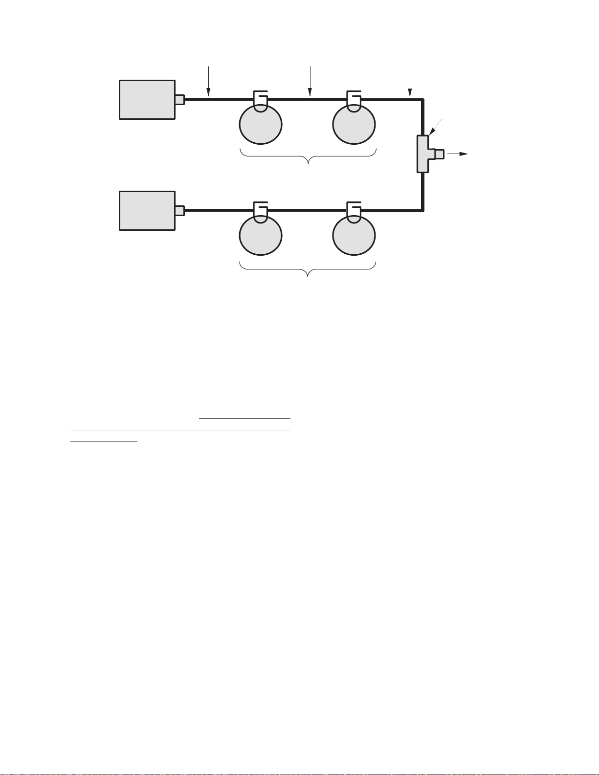
Figure 1 on page 2 shows the functional block diagram of a typical four-cavity Vari-Notch duplexer
system. Six and eight cavity systems are similar
except for the extra filters in each channel. The
photograph shown in figure 2 on page 3 is the
front view of a typical four-cavity Vari-Notch duplexer. Each of the physical components in the
system is labeled with the field adjustable parts
shown in emboldened italics.
Model
Number
28-13-01F 30-40 400 0.3 1.5 90 50
28-14-01F 38-50 400 0.3 1.5 90 50
28-28-02A/G 66-88 400 0.35 1.5 85 50
28-36-02A/G 132-150 400 0.5 1.5 85 50
28-36-11E/G 132-150 400 0.3 2.2 100 50
28-37-02A/G 144-174 400 0.5 1.5 85 50
28-37-11E/G 144-174 400 0.3 2.2 100 50
28-37-08G 144-174 400 0.24 3 100 50
28-65-01A 406-430 350 1.5 1.5 90 50
28-65-05A/G 406-430 350 0.7 2.2 100 50
28-70-01A 450-470 350 1.5 1.5 90 50
28-70-07A/G 450-470 350 0.7 2.2 100 50
28-69-01A 470-512 350 1.5 1.5 90 50
28-69-04A 470-512 350 0.7 2.2 100 50
TX RX Systems Inc. Manual 7-9177-1 09/19/97 Page 1
Frequency Range
(MHz)
Table 1: Vari-Notch Duplexer electrical specifications (for 6.625" diameter cavities).
Power
Rating
(Watts)
Min. Freq.
Separation
(MHz)
Insertion
Loss
(dB)
Isolation
(dB)
Per Chan. Bet Chan.
Page 6
High
a
Frequency
Equipment
Low
Frequency
Equipment
RG214 or RG142
Double-Shielded Cable
(Supplied by customer)
Rejection notch tuned to low frequency
Rejection notch tuned to high frequency
TYPICAL FOUR CAVITY VARI-NOTCH FILTER
Interconne ct C a b le
λ
or 3/4 λ of this)
(1/4
(channels pass freq.)
Vari-
Notch
Filter
Passband tuned to high frequency
Vari-
Notch
Filter
Passband tuned to low frequency
Vari-
Notch
Filter
Vari-
Notch
Filter
Antenna Cable
(1/2 λ of the other)
(channels pass freq.)
Antenna
Junction
To
Antenn
Figure 1: Block diagram of a typical four-cavity Vari-Notch Duplexer (6.625" diameter cavities).
UNPACKING
Care should be used when removing the duplexer
from it's shipping container to avoid unnecessary
damage. It is important to visually inspect the duplexer for any shipping damages as soon as possible after taking delivery.
It is the customers
responsibility to file any necessary damage claims
with the carrier.
Vari-Notch duplexers are rugged devices but may
become detuned if jostled or dented during shipping. The most easily damaged parts of the duplexer are the tuning rods. These rods are marked
where they exit from the locking nut with a dab of
red varnish or other color/type of paint. If this seal
appears to be broken it may indicate that the system has been detuned in transit.
INSTALLATION
Vari-Notch duplexers should be securely installed
in a dry, vibration-free environment. Attachment of
the cavity shells to a grounding bus is recommended in order to maximize lightning protection.
A lightning protection device placed in the antenna
feedline, preceding the duplexer, is also recommended. High quality double shielded coaxial cable terminated with quality connectors (N-type) are
recommended for connecting the transmitter and
receiver to the duplexer, and are available from
TX RX Systems Inc. It is also important to observe
the power handling ratings of cables in transmit
systems.
Mount the duplexer in it's permanent operating position using suitable hardware. Connect the two
transmitters (or transmitter/receiver) and the antenna feedline to the duplexer making sure to connect the correct equipment to the correct port.
Labels are affixed next to each port (port labels) to
help you make the right connections. In addition, a
specification tag will be found in a plastic bag attached to one of the tuning rods. The frequency
that each cavity group is tuned to will appear on
either the port labels or the specification tag. The
duplexer is now ready for normal operation. No
tuning is required if the frequencies (high frequency and low frequency) found on the port
labels/specification tag matches the actual operating frequencies.
MAINTENANCE
No special maintenance is required. Vari-Notch
duplexers are passive devices of rugged electrical
and mechanical design. They are tuned at the factory for the original design requirements and require no further adjustment or maintenance.
These devices will stay properly tuned unless they
have been physically damaged or are tampered
with. Check for loose or corroded connectors on
TX RX Systems Inc. Manual 7-9177-1 09/19/97 Page 2
Page 7

Resonant
Cavity
Equipment
Port
Equipment
Port
Coarse Tuning Rod
Coarse Tuning Lock
10-32 Cap Screw
Interconnect
Cable
Variable Capacitor
Access Barrel
Loop Plate
Hole Cover
Loop Plate
Hold Down Screws
Antenna
Cable
Antenna
Port
Loop Plate
Assembly
Calibration
Index
Interconnect
Cable
Mounting
Bar
Fine Tuning Rod
Fine Tuning Lock
Knurled Thumb Nut
Antenna
Cable
Figure 2: Top view of a typical four-cavity Vari-Notch Duplexer (6.625" diameter cavities).
the interconnect cables whenever an inspection is
performed on other station equipment.
Because duplexers are passive devices, field repairs are rarely required. Field repair of duplexers
is limited to the replacement or repair of damaged
cables. Cavity damage, when it occurs, is usually
due to catastrophic failure from lightning or power
far in excess of the duplexers rating. If cavity problems are suspected, the unit should be returned to
the factory for repair. Due to the critical alignment
of parts inside of the cavity resonators, field repair
is not recommended.
TUNING
Vari-Notch duplexers are originally pre-tuned at
the factory to the customers specification. To retune the duplexer, each resonant cavity must be
separated from the group and adjusted individually. Then the individual cavities are re-connected
and each channel is fine tuned to peak it's overall
response. When reconnecting the assembly, it is
mandatory that each filter and cable be replaced in
it's original position.
There are two adjustable parameters found in a
Vari-Notch filter; the
tion notch
. Adjustment of the coarse and fine tun-
pass frequency
and the
rejec-
ing rods will allow the filters passband to be
centered at the desired frequency. The rejection
notch frequency is adjusted by turning the variable
capacitor located on the loop plate assembly.
The insertion loss of a cavity is determined by the
position of the loop plate and is not field adjustable. The loop plate on a 6.625" cavity should
never be loosened or moved from it's factory
preset position.
It is also important to note that the insertion loss
specification in table 1 for each of the different
models, is the total insertion loss for each channel
of that model. For instance, the specification for
model 28-13-01F is 1.5 dB, this means both the
high and low frequency channels will each have a
TX RX Systems Inc. Manual 7-9177-1 09/19/97 Page 3
Page 8

total of 1.5 dB of insertion loss. The total insertion
loss is the sum of losses from each cavity in the
channel as well as from the interconnecting cables
between the cavities.
3. Final tune the passband.
4. Final tune the rejection notch, always the last
adjustment made.
Required Equipment
Due to the sensitivity of the adjustments, it is
strongly recommended that the proper equipment
be used when tuning the individual filters, otherwise the filter should be sent to the factory or an
authorized representative for retuning. The following equipment or it's equivalent is recommended in
order to properly perform the tuning adjustments
for the Vari-Notch duplexer.
1. IFR A-7550 spectrum analyzer with optional
tracking generator installed.
2. 5/32" hex wrench.
3. Double shielded coaxial cable test leads
(RG142 B/U or RG223/U).
4. 50 ohm load with at least -35 dB return loss
(1.10:1 VSWR). The JFW Industries model
50T-007 or equivalent.
5. Female union (UG29-N or UG914-BNC).
6. Return Loss Bridge
(Eagle model# RLB150N3A).
7. Insulated tuning tool (TX RX Systems Inc.
part# 95-00-01).
Tuning Procedure
Tuning of the filter requires adjustment of the
passband
and the
rejection notch
. The passband
is adjusted while observing the return loss response and the rejection notch is adjusted by
monitoring the output of a tracking generator after
it passes through the filter.
WARNING - Tuning while under transmit power can result in damage to the
duplexer.
PASSBAND
The peak of the passband will correspond very
closely to the point of minimum reflected energy
from the filter and maximum forward power
through it. A transmitter connected to the filter will
operate best when the reflected energy is lowest,
therefore the return loss response will be used to
set the passband. The passband can be checked
and adjusted using the following procedure.
Checking the passband
1. A zero reference for return loss must be established at the IFR A-7550 prior to checking the
passband frequency, this is done by connecting the return loss bridge to the analyzer / generator as shown in figure 3.
dBm
40
30
20
10
0
-10
-20
-30
-40
ANALYZER
INPUT
200
KHz/DIV
dB ATT GEN
40
MHz
dBM
0
300
KHz RES
10
MSEC
GENERATE
OUTPUT
All Vari-Notch filters should be temporarily removed from the system and tuned on the bench
using test instrumentation only. Do not adjust the
filters while they are under transmit power. To insure proper tuning of the 6.625" Vari-Notch filter,
RLB - 150 BRIDGE
REFLECTED
all adjustments should be performed in the following order:
LOAD
SOURCE
1. Rough tune the passband.
2. Rough tune the rejection notch.
TX RX Systems Inc. Manual 7-9177-1 09/19/97 Page 4
Figure 3: Setting the return loss reference.
Page 9

2. Set-up the analyzer / generator for the desired
frequency (center of display) and for a vertical
scale of 10 dB/div.
3. Do not connect the return loss bridge (RLB) to
the cavity, leave the "load" port on the bridge
open. This will supply the maximum amount of
reflected energy to the analyzer input.
4. Insure that the IFR A-7550 menu's are set as
follows: DISPLAY - line
MODE - live
FILTER - none
SETUP - 50 ohm/dBm/gen1.
decreased by pulling it out; the exact opposite of
the coarse tuning rod. For ease in making adjustments, rotate and slide the rods while gently tapping on them with a screwdriver handle or other
small tool. This will break the surface tension on
the probe contact fingers and allow smoother
movement of the tuning rods.
Cavity Tuning Tip
When tuning a cavity that has been in service for
some time it is not unusual to find the main tuning
rod hard to move in or out. This occurs because
TX RX Systems Inc. uses construction techniques
borrowed from microwave technology that provide
5. The flat line across the screen is the return loss
curve. Select the "MODE" main menu item and
then choose the "STORE " command.
6 Next select the "DISPLAY" main menu item
and choose the "REFERENCE" command.
This will cause the stored value
to be displayed
at the center of the screen as the 0 dB reference value.
7. Connect the "load" port on the RLB to the input
of the loop plate, make sure the output of the
loop plate is connected to a 50 ohm load, refer
to figure 4. The display will now present the return loss curve for the 6.625" Vari-Notch filter
being measured. The passband is that fre-
quency range over which the return loss is
15 dB or greater.
Adjusting the passband
Set the fine tuning rod at it's mid-point. Adjust the
passband by setting the peak (maximum negative
value) of the return loss curve at the desired passband frequency (should be the center-vertical
graticule line on the IFR A-7550's display). Refer
to figure 4.
The resonant frequency is adjusted by using the
coarse tuning rod, which is a sliding adjustment
(invar rod) that rapidly tunes the response curve
across the frequency range of the filter. Resonant
frequency is increased by pulling the rod out of the
cavity and is decreased by pushing the rod into
the cavity. Additionally, the fine tuning rod, also a
sliding adjustment (silver-plated-brass rod) allows
a more precise setting of the frequency after the
course adjustment is made. The frequency is increased by pushing the fine tuning rod in and is
200
dBm
40
30
20
10
0
-10
-20
-30
-40
ANALYZER
INPUT
VARI-NOTCH
FILTER
KHz/DIV
dB ATT GEN
40
REFLECTED
20
15
0
5
0
MHz
0
RLB - 150 BRIDGE
LOAD
dBM
Figure 4: Checking the passband.
300
KHz RES
10
GENERATE
SOURCE
50 OHM LOAD
MSEC
OUTPUT
TX RX Systems Inc. Manual 7-9177-1 09/19/97 Page 5
Page 10

large area contact surfaces on our tuning probes.
These silver plated surfaces will actually form
pressure welds which maintain excellent conductivity. The pressure weld develops over time and
must be broken in order for the tuning rod to
move. This is easily accomplished by gently tapping the tuning rod with a plastic screwdriver handle or small hammer so it moves into the cavity.
The pressure weld will be broken with no damage
to the cavity.
Once the desired response is obtained using the
coarse and fine tuning rods, they are "locked" into
place. The coarse rod is secured by tightening the
10-32 cap screw and the fine tuning rod is held in
place by tightening the knurled thumb nut. Failure
to lock the tuning rods will cause a loss of temperature compensation and detuning of the cavity.
REJECTION NOTCH
The rejection notch will track with the tuning of the
passband and therefore should be the last adjustment made to the 6.625" Vari-Notch filter. The rejection notch is adjusted by changing the amount
of capacitance in the loop assembly. The capacitor is variable and is either an air-plate or tubular
piston type depending upon the frequency range
of the filter. The air-plate type has a red mark
painted on the access barrel and one-half of the
adjusting screw, when the red marks line up the
maximum capacitance is achieved. On UHF models (400 MHz and over) the capacitor access barrel is omitted and a 10-32 inch screw must then be
removed from the loop plate assembly to gain access to the piston trimmer under the plate.
FINE TUNING THE CHANNELS
Once all of the individual filters have been tuned,
each of the channels as a whole must be fine
tuned. First the passband for both channels and
then the rejection notches. The following is a step
by step procedure for fine tuning the channels and
completes the re-tuning of the duplexer.
1. Reassemble the duplexer by reinstalling the
cavities and interconnect cables in their original
locations.
2. The
passband
for the channels are fine tuned
first, in a manner very similar to tuning a single
cavity.
3. A zero reference for return loss must be established at the IFR-7550. Connect the RLB to the
analyzer / generator as shown in figure 3.
dBm
10
0
-10
-20
-30
-40
-50
-60
-70
ANALYZER
INPUT
200
KHz/DIV
dB ATT GEN
40
MHz
dBM
0
300
KHz RES
10
GENERATE
MSEC
OUTPUT
Checking the rejection notch
1. The rejection notch is checked by connecting
the tracking generator to the input of the cavity
filter while the spectrum analyzer is connected
to the output, as illustrated in figure 5.
2. Insure that the IFR A-7550 menu's are set as
follows: DISPLAY - line
MODE - live
VARI-NOTCH
FILTER
20
15
0
5
0
FILTER - none
SETUP - 50 ohm/dBm/gen1.
Adjusting the rejection notch
The notch is adjusted by turning the variable capacitor. Because of the filters sensitivity to tool
contact, an insulated tuning tool must be used to
make the adjustment.
TX RX Systems Inc. Manual 7-9177-1 09/19/97 Page 6
Figure 5: Checking the rejection notch.
Page 11

4. Set-up the analyzer / generator to the desired
frequency (center of display) and for a vertical
scale of 10 dB/div.
with the 50 ohm load. The equipment port of
the remaining duplexer channel is left disconnected, refer to figure 6.
5. Do not connect the RLB to the duplexer at this
time, leave the "load" port on the bridge open.
This will supply the maximum amount of reflected energy to the analyzer input.
6. Insure that the IFR A-7550 menu's are set as
follows: DISPLAY - line
MODE - live
FILTER - none
SETUP - 50 ohm/dBm/gen1.
7. The flat line across the screen is the return loss
curve. Select the "MODE" main menu item and
then choose the "STORE " command.
8. Next select the "DISPLAY" main menu item
and choose the "REFERENCE" command.
This will cause the stored value
to be displayed
at the center of the screen as the 0 dB reference value.
9. Connect the "load" port on the RLB to the
equipment port of the channel to be fine tuned.
Terminate the duplexers antenna connector
10. The display will now present the combined return loss curve for all of the cavities in the
channel. The channels passband is that frequency range over which the return loss is 15
dB or greater.
11. Fine tune the passband for the entire channel
(for maximum return loss) by gently adjusting
the positions of the fine tuning rods (coarse
rods if needed) moving between cavities as
required. Once the desired response is obtained "lock" the tuning rods into place by
tightening the 1/4" shaft lock nuts and the
knurled thumb nuts on each filter.
12. Move the cable from the RLB's "load" port to
the equipment port of the other channel. This
will allow the remaining duplexer channel to be
fine tuned. Reset the analyzer / generator center frequency. Repeat steps 10 and 11.
13. The
rejection notch
for each of the channels
must be fine tuned next.
500
dBm
dBm
KHz/DIV
40
30
20
10
0
-10
-20
-40
-40
dB ATT GEN
40
ANALYZER
INPUT
Reflected
RLB - 150 BRIDGE
(RLB)
MHz
Load
dBM
0
KHz RES
Source
300
10
GENERATE
Vari-
Notch
Filter
High Frequency Pass Channel
Reject the Low Frequency Channel
MSEC
OUTPUT
Vari-
Notch
Filter
Low Frequency Pass Channel
Reject the High Frequency Channel
Figure 6: Equipment setup for fine tuning the passband of each channel.
Vari-
Notch
Filter
Vari-
Notch
Filter
50
Load
Ω
TX RX Systems Inc. Manual 7-9177-1 09/19/97 Page 7
Page 12

14. Terminate the antenna connector with a 50
ohm load. Connect the output of the tracking
generator to the equipment port of one of the
duplexer channels and the spectrum analyzer
input to the equipment port of the remaining
channel as shown in figure 7.
15. Set-up the analyzer / generator to sweep
across the rejection notch frequency of the
channel being tuned. The center of the display
should be set to the desired center frequency
of the rejection notch being adjusted. Set the
vertical scale of the analyzer / generator to 10
dB/div.
The display will now show most of the rejection notch. Using the analyzer's attenuation
control adjust the amount of attenuation so
that the "peak" or lowest value on the rejection
notch is displayed.
18. The cavities rejection notches are adjusted
(for maximum rejection) by gently turning the
variable capacitors in the loop plate assemblies. Move between filters as needed.
Because of the filters sensitivity to tool contact, an insulated tuning tool must be used to
make the adjustment..
Keep in mind that the high frequency channel
has it's rejection notch set to reject the low frequency signal and vice-versa for the rejection
notch of the low frequency channel.
16. Insure that the IFR A-7550 menu's are set as
follows: DISPLAY - line
MODE - live
FILTER - none
SETUP - 50 ohm/dBm/gen1
17. Set the analyzers attenuation control so that
the 0 dBm level is at the top of the display.
dBm
dBm
-30
-40
-50
-60
-70
-80
-90
-100
-110
ANALYZER
INPUT
50
KHz/DIV
dB ATT GEN
30
MHz
dBM
0
300
KHz RES
10
MSEC
GENERATE
OUTPUT
19. Adjust the rejection notch of the remaining
cavities by changing the sweep frequency of
the analyzer / generator to match the new rejection notch frequency. The equipment stays
connected as it is.
20. Repeat step 17 and 18 for the remaining
channel (cables and equipment stay connected where they are).
21. With the tuning completed, reconnect the
equipment cables and antenna feedline. Test
the system for proper operation.
Vari-
Notch
Filter
High Frequency Pass Channel
Reject the Low Frequency Channel
Vari-
Notch
Filter
Vari-
Notch
Filter
Vari-
Notch
Filter
50
Load
Ω
Low Frequency Pass Channel
Reject the High Frequency Channel
Figure 7: Equipment setup for fine tuning the rejection notch of each channel.
TX RX Systems Inc. Manual 7-9177-1 09/19/97 Page 8
Page 13

DUPLEXER PROBLEMS AND REMEDIES
Duplexers are passive devices requiring little or no service once installed in a system. The proper design and application of a given Duplexer will give
years of trouble free service. When problems do occur in a duplex system it is necessary to identify as many abnormal conditions as possible to zero
in on the specific cause of the problem. Unfortunately, there are only a few measurable or observable performance indicators at the disposal of the
field serviceman, and any number of conditions may exist, even simultaneously, which are responsible for the observed phenomena. Most Duplexer
installation problems fall into three categories. Each of these three conditions will be treated separately, using the typical cause and remedy approach.
A. High input VSWR
B. Excessive loss
C. Desensitization of the receiver
when transmitter is keyed
PROBLEM POTENTIAL CAUSE
A B C
●●
●●
●
●●
●●●
●●
●●
●
●
●
●
●
●
●
●
●
●
THE NUMBER AT RIGHT CORRESPONDS TO THE APPROPRIATE NUMBERED REMEDY PARAGRAPH
Reverse labeling of Tx and Rx terminals.
Unit tuned to wrong frequencies.
Bad antenna or interconnect cables.
Use of between series adapters, especially UHF types.
Duplexer detuned in shipment.
Water has entered the Duplexer antenna connector from the antenna feed line.
Spurious Tx output is being reflected by the selective Duplexer input terminal and observed on the wattmeter, the
wattmeter being unable to discriminate between on-frequency and off-frequency energy.
Bad joint in a cable or antenna system beyond the antenna terminal of the Duplexer. All lines may show zero
reflected power, but noise can still be produced when a corroded or indefinite metal-to-metal contact is exposed to
RF energy. When this occurs beyond the Duplexer, it cannot be filtered out, and the noise backs up into the
receiver
Adverse cable length between Duplexer and transmitter using varactor or broadband hybrid combining type
transmitter outputs. Even though the Duplexer VSWR is flat on frequency, the reflected impedance of the
Duplexer off resonance, transformed by changing cable lengths, can cause parasitics to be generated.
Duplexer transmitter mixing with another outside transmitter, producing intermodulation on or near the receiver
frequency.
Transmitter cable leading to Duplexer in close proximity to Duplexer antenna or receiver cable. This is usually
only a problem on close separation Duplexers, (1.0 MHz or less) where the 85 to 100 dB isolation is decreased by
adverse coupling, created by running these cables too close together for too great a distance.
Inadequate shielding of transmitter and receiver modules in the repeater.
Insufficient duplex isolation for the application.
A spurious transmitter response outside of the normal Duplexer isolation band or inadequacy of notch filter type
Duplexers to suppress a wide enough band of Tx noise to protect the receiver.
Impedance change in antenna due to icing. VSWR increase may be sufficient to reflect back through the Duplexer
and upset transmitter tuning, causing parasitics, which are not suppressed sufficiently by the Duplexer.
The addition of a broadband power amplifier to a low power transmitter. The noise floor of the low power radio is
raised by an amount equal to the gain of the power amplifier, and in addition, the power amplifier will contribute its
own noise. Power amplifiers are just as prone to the generation of parasitics as transmitters, and may be triggered
by an adverse cable length between power amplifier and Duplexer, a problem covered above.
Excessive loss with changing temperature and apparent Duplexer detuning.
1
2
3
4
5
6
7
8
9
10
11
12
13
14
15
16
17
REMEDIES
1. Tune a signal generator to the receive frequency and inject it into the antenna terminal, sampling for the signal at each equipment terminal.
Reverse the labels if necessary. It may be that the unit was ordered to the reverse frequencies. If so, the label will indicate this. If the duplexer
is symmetrical in design (usually indicated by the same number of Tx and Rx filter sections) just reverse the equipment labels and operate.
Generally, no damage will be done to the duplexer when operated in reverse for a short time period. If other adverse symptoms appear, contact the factory.
TX RX Systems Inc. Manual 7-9177-1 09/19/97 Page 9
Page 14

2. Check the unit label. If needed, the duplexer may be field tuned. Consult the instructions and/or the factory if the duplexer is still under
warranty or beyond field tuning capability.
3. Check cable, by substitution, using a termaline wattmeter, or a thruline wattmeter into a known good load. Check the antenna line input for
reflected power.
4. To eliminate high input VSWR reduce the number of between series adapters by making up proper interconnect cables. UHF connectors
are non-constant impedance, and certain combinations can transform a 1.1:1 VSWR into a 2.0:1, or vice versa.
5. Consult the instruction manual for field tuning procedures, or the factory, if the unit is still under warranty or beyond field tuning capability.
(We trust that our products will not be prone to this problem).
6. Consult the factory. The affected antenna cables may be field replaceable, or a "baking out" process may be possible.
7. To prove this condition, place a bandpass filter between the Tx and duplexer to clean up the spurious, and put the wattmeter between the
bandpass filter and the duplexer to measure reflected power from the duplexer. The bandpass filter selectivity should be equal to or better
than that of the duplexer at about the 3.0 dB points.
8. Operate the duplex system into a dummy load. If no desensitization occurs, check out all lines, antennas, and look for potential bad joints
close to the radiating antenna where re-radiation of noise may be possible back into the antenna system receiver. Loose metal-to-metal
contacts on tower guying systems have also been known to create system noise. Note the effect of vibrating tower guys on system
noise.
9. Change the length of cable between the transmitter and duplexer, traversing through a half wave in increments of between 1 and 2 inches
until the desensitization ceases or is minimal. A ferrite isolator will also cure this condition when it is installed between the transmitter and
duplexer. However, this is a much more expensive remedy.
10. If the IM is in the duplex transmitter, a ferrite isolator in the duplex transmitter line (NOT antenna line) will show this by either reducing or
eliminating it. More isolation can be obtained by cascading isolators if needed. However, IM of this magnitude indicates the system
should be studied for possible revision to reduce the production of this IM.
11. Cables such as RG-8a/u and RG-213/u should be kept at least 3-4" apart over 5'-10' runs. Use of double shielded cable will reduce the
susceptibility to this problem.
12. Consult the radio manufacturer. This condition can be verified by operating the transmitter into a dummy load while injecting a minimum
quieting signal into the receiver. Some radios require special modifications before they are suitable for repeater operation.
13. If this problem is suspected, contact the radio manufacturer for recommended duplex isolation for Tx noise suppression and carrier suppression. Duplexer isolation should be measured first per instruction manual to verify rated specifications are present. If more duplex isolation is required, contact TX RX SYSTEMS for recommended filtering.
14. Consult the factory. Bandpass filter tests can be made to confirm this. In extreme cases, adjustments to the transmitter may be required.
15. Either de-ice the antenna, or use an antenna less sensitive to ice. A ferrite isolator can also be put at the transmitter output to improve the
impedance match. Ferrite isolators cannot be put in antenna lines, as they will attenuate Rx signals.
16. A mismatch may possibly be reduced by lengthening the cable which runs between the power amplifier output and the duplexer input until
the receiver desensitization disappears, as follows
30 MHz to 512 MHz RANGE; BNC or N type adapters may be inserted in the original cable, one at a time and not to exceed a total of 1/2
wavelength, until desensitization disappears.
800 MHz to 1.3 GHz RANGE; Prepare a cable length 3/4" longer than the original cable and insert. If desensitization does not disappear,
repeat with cables each 3/4" longer than the previous length, not to exceed 1/2 wavelength.
17. We find that this cause most commonly relates to shifting impedance of the transmitter or power amplifier with temperature. The duplexer
appears detuned, since a "conjugate match" (canceling reactance, and matching resistance component) is approached by shifting the duplexer passband above or below the 50 ohm point, as determined by an increase in output power on the wattmeter. In this case, temperature control of the room is the only answer, other than upgrading the transmitter.
TX RX Systems Inc. Manual 7-9177-1 09/19/97 Page 10
Page 15

POWER IN/OUT
t
e
VS.
INSE R T ION LOS S
The graph below offers a convenient means of determining the insertion loss of filters, duplexers,
multicouplers and relat ed pr oducts. The gr aph on t he back page wi l l al l ow you t o quic kly det er mine VSWR. I
should be remembered that the fiel d accuracy of watt meter readings i s subject to consider able variance du
to RF connector VSWR and basic wattmeter accuracy, particularly at low end scale readings. However,
allowing for these variances, these graphs should prove to be a useful reference.
INSERTION LOSS (dB)
500
400
300
250
200
150
125
INPUT POWER (WATTS)
100
6.5
7.0
5.5
5.0
6.0
4.5
3.5
4.0
2.5
3.0
2.0
1.5
1.0
.25
.50
75
50
50
75 100
125 150 200
250
300
400
500
OUTPUT POWER (WATTS)
FOR LOWER POWER LEVELS, DIVIDE
BOTH SCALES BY 10 (5 TO 50 WATTS)
TX RX Systems Inc. Manual 7-9177-1 09/19/97 Page 11
Page 16

500
400
300
200
100
50
40
30
POWER FWD./REV.
VS.
VSWR
V
S
W
R
1.1:1
1.15:1
20
10
FORWARD POWER (WATTS)
5.0
4.0
3.0
2.0
1.0
0.5
40
20
10
8.0 6.0
4.0
2.0
1.0 0.8
0.6
0.4
1.2:1
1.25:1
1.3:1
1.4:1
1.5:1
1.6:1
1.8:1
2.0:1
2.5:1
3.0:1
0.2
REFLECTED POWER (WATTS)
FOR OTHER POWER LEVELS, MULTIPLY
BOTH SCALES BY THE SAME MULTIPLIER
TX RX Systems Inc. Manual 7-9177-1 09/19/97 Page 12
Page 17

Power Ratio and Voltage Ratio to Decibel
Conversion Chart
Loss or Gain Power Ratio Voltage Ratio
+9.1 dB 8.128 2.851
-9.1 dB 0.123 0.351
- dB +- dB +
Voltage
Ratio
1 1 0 1 1
0.989 0.977 0.1 1.012 1.023
0.977 0.955 0.2 1.023 1.047
0.966 0.933 0.3 1.035 1.072
0.955 0.912 0.4 1.047 1.096
0.944 0.891 0.5 1.059 1.122
0.933 0.871 0.6 1.072 1.148
0.923 0.851 0.7 1.084 1.175
0.912 0.832 0.8 1.096 1.202
0.902 0.813 0.9 1.109 1.23
0.891 0.794 1 1.122 1.259
0.881 0.776 1.1 1.135 1.288
0.871 0.759 1.2 1.148 1.318
0.861 0.741 1.3 1.161 1.349
0.851 0.724 1.4 1.175 1.38
0.841 0.708 1.5 1.189 1.413
0.832 0.692 1.6 1.202 1.445
0.822 0.676 1.7 1.216 1.479
0.813 0.661 1.8 1.23 1.514
0.804 0.646 1.9 1.245 1.549
0.794 0.631 2 1.259 1.585
0.785 0.617 2.1 1.274 1.622
0.776 0.603 2.2 1.288 1.66
0.767 0.589 2.3 1.303 1.698
0.759 0.575 2.4 1.318 1.738
0.75 0.562 2.5 1.334 1.778
0.741 0.55 2.6 1.349 1.82
0.733 0.537 2.7 1.365 1.862
0.724 0.525 2.8 1.38 1.905
0.716 0.513 2.9 1.396 1.95
0.708 0.501 3 1.413 1.995
0.7 0.49 3.1 1.429 2.042
0.692 0.479 3.2 1.445 2.089
0.684 0.468 3.3 1.462 2.138
0.676 0.457 3.4 1.479 2.188
0.668 0.447 3.5 1.496 2.239
0.661 0.437 3.6 1.514 2.291
0.653 0.427 3.7 1.531 2.344
0.646 0.417 3.8 1.549 2.399
0.638 0.407 3.9 1.567 2.455
0.631 0.398 4 1.585 2.512
0.624 0.389 4.1 1.603 2.57
0.617 0.38 4.2 1.622 2.63
0.61 0.372 4.3 1.641 2.692
0.603 0.363 4.4 1.66 2.754
0.596 0.355 4.5 1.679 2.818
0.589 0.347 4.6 1.698 2.884
0.582 0.339 4.7 1.718 2.951
0.575 0.331 4.8 1.738 3.02
0.569 0.324 4.9 1.758 3.09
Power
Ratio
dB
Voltage
Ratio
Power
Ratio
Voltage
Ratio
0.562 0.316 5 1.778 3.162
0.556 0.309 5.1 1.799 3.236
0.55 0.302 5.2 1.82 3.311
0.543 0.295 5.3 1.841 3.388
0.537 0.288 5.4 1.862 3.467
0.531 0.282 5.5 1.884 3.548
0.525 0.275 5.6 1.905 3.631
0.519 0.269 5.7 1.928 3.715
0.513 0.263 5.8 1.95 3.802
0.507 0.257 5.9 1.972 3.89
0.501 0.251 6 1.995 3.981
0.496 0.246 6.1 2.018 4.074
0.49 0.24 6.2 2.042 4.169
0.484 0.234 6.3 2.065 4.266
0.479 0.229 6.4 2.089 4.365
0.473 0.224 6.5 2.113 4.467
0.468 0.219 6.6 2.138 4.571
0.462 0.214 6.7 2.163 4.677
0.457 0.209 6.8 2.188 4.786
0.452 0.204 6.9 2.213 4.898
0.447 0.2 7 2.239 5.012
0.442 0.195 7.1 2.265 5.129
0.437 0.191 7.2 2.291 5.248
0.432 0.186 7.3 2.317 5.37
0.427 0.182 7.4 2.344 5.495
0.422 0.178 7.5 2.371 5.623
0.417 0.174 7.6 2.399 5.754
0.412 0.17 7.7 2.427 5.888
0.407 0.166 7.8 2.455 6.026
0.403 0.162 7.9 2.483 6.166
0.398 0.159 8 2.512 6.31
0.394 0.155 8.1 2.541 6.457
0.389 0.151 8.2 2.57 6.607
0.385 0.148 8.3 2.6 6.761
0.38 0.145 8.4 2.63 6.918
0.376 0.141 8.5 2.661 7.079
0.372 0.138 8.6 2.692 7.244
0.367 0.135 8.7 2.723 7.413
0.363 0.132 8.8 2.754 7.586
0.359 0.129 8.9 2.786 7.762
0.355 0.126 9 2.818 7.943
0.351 0.123 9.1 2.851 8.128
0.347 0.12 9.2 2.884 8.318
0.343 0.118 9.3 2.917 8.511
0.339 0.115 9.4 2.951 8.71
0.335 0.112 9.5 2.985 8.913
0.331 0.11 9.6 3.02 9.12
0.327 0.107 9.7 3.055 9.333
0.324 0.105 9.8 3.09 9.55
0.32 0.102 9.9 3.126 9.772
Power
Ratio
dB
Voltage
Ratio
Power
Ratio
Bird Technologies Group TX RX Systems Inc.
Page 18

Power Conversion Chart
dBm to dBw to Watts to Volts
dBm dBw Watts
80 50 100kW 2236
75 45 31.6 kW 1257
70 40 10.0 kW 707
65 35 3.16 kW 398
60 30 1000 224
55 25 316 126
50 20 100 70.7
45 15 31.6 39.8
40 10 10.0 22.4
38 8 6.31 17.8
36 6 3.98 14.1
34 4 2.51 11.2
32 2 1.58 8.90
30 0 1.00 7.07
29 -1 0.79 6.30
28 -2 0.63 5.62
27 -3 0.50 5.01
26 -4 0.40 4.46
25 -5 0.32 3.98
24 -6 0.25 3.54
23 -7 0.20 3.16
22 -8 0.16 2.82
21 -9 0.13 2.51
20 -10 0.10 2.24
19 -11 79 mW 1.99
Volts 50 Ω
dBm dBw Watts
18 -12 63 mW 1.78
17 -13 50 mW 1.58
16 -14 40 mW 1.41
15 -15 32 mW 1.26
14 -16 25 mW 1.12
13 -17 20 mW 1.00
12 -18 16 mW 0.890
11 -19 13 mW 0.793
10 -20 10 mW 0.707
9 -21 7.9 mW 0.630
8 -22 6.3 mW 0.562
7 -23 5.0 mW 0.501
6 -24 4.0 mW 0.446
5 -25 3.2 mW 0.398
4 -26 2.5 mW 0.354
3 -27 2.0 mW 0.316
2 -28 1.6 mW 0.282
1 -29 1.3 mW 0.251
0 -30 1.0 mW 0.224
-5 -35 316 uW 0.126
-10 -40 100 uW 0.071
-15 -45 31.6 uW 0.040
-20 -50 10 uW 0.022
-25 -55 3.16 uW 0.013
-30 -60 1 uW 0.007
Volts 5 0 Ω
Bird Technologies Group TX RX Systems Inc.
Page 19

Return Loss vs. VSWR
Watts to dBm
Return Loss VSWR
30 1.06
25 1.11
20 1.20
19 1.25
18 1.28
17 1.33
16 1.37
15 1.43
14 1.50
13 1.57
12 1.67
11 1.78
10 1.92
9 2.10
Watts dBm
300 54.8
250 54.0
200 53.0
150 51.8
100 50.0
75 48.8
50 47.0
25 44.0
20 43.0
15 41.8
10 40.0
5 37.0
4 36.0
3 34.8
2 33.0
1 30.0
dBm = 10log P/1mW
Where P = power (Watt)
Insertion Loss
Input Power (Watts)
50 75 100 125 150 200 250 300
3 25 38 50 63 75 100 125 150
2.5 28 42 56 70 84 112 141 169
2 32 47 63 79 95 126 158 189
1.5 35 53 71 88 106 142 177 212
1 40 60 79 99 119 159 199 238
Insertion Loss
.5 45 67 89 111 134 178 223 267
Output Power (Watts)
Free Space Loss
Distance (miles)
.25 .50 .75 1 2 5 10 15
150 68 74 78 80 86 94 100 104
220 71 77 81 83 89 97 103 107
460 78 84 87 90 96 104 110 113
860 83 89 93 95 101 109 115 119
940 84 90 94 96 102 110 116 120
Frequency (MHz)
1920 90 96 100 102 108 116 122 126
Free Space Loss (dB)
Free space loss = 36.6 + 20log D + 20log F
Where D = distance in miles and F = frequency in MHz
Bird Technologies Group TX RX Systems Inc.
Page 20

8625 Industrial Parkway, Angola, NY 14006 Tel: 716-549-4700 Fax: 716-549-4772 sales@birdrf.com www.bird-technologies.com
 Loading...