


SERVICE MANUAL
MS330IA031203
II
INDEX |
|
1. INTRODUCTION |
1-1 |
2. FUNCTIONAL PARTS DESCRIPTION |
2-1 |
2.1. Optical system |
2-1 |
2.1.1. Constitutive parts |
2-1 |
2.1.2. System description |
2-1 |
2.1.3. Physical description |
2-2 |
2.1.4. Signal conditioning |
2-2 |
2.1.5. Adjustment |
2-7 |
2.1.6. Precautions and maintenance |
2-7 |
2.2. Aspiration system |
2-7 |
2.2.1. Components |
2-7 |
2.2.2. System description |
2-7 |
2.2.3. Physical description |
2-8 |
2.2.4. Programmable parameters |
2-8 |
2.2.5. Programming |
2-8 |
2.2.6. Adjustment |
2-8 |
2.2.7. Precautions and maintenance |
2-9 |
2.3. Thermostatization system |
2-9 |
2.3.1. Components |
2-9 |
2.3.2. System description |
2-9 |
2.3.3. Physical description |
2-14 |
2.3.4. Programming |
2-14 |
2.3.5. Adjustment |
2-14 |
2.3.6. Precautions and maintenance |
2-14 |
2.4. Communications system |
2-15 |
2.4.1. Channel type |
2-15 |
2.4.2. Channel characteristics |
2-15 |
2.4.3. Information transmitted |
2-15 |
2.4.4. Programming |
2-16 |
2.5. Block diagram |
2-18 |
2.5.1. Logarithmic amplifier |
2-18 |
2.5.2. Analogic/Digital converter |
2-18 |
2.5.3. Lamp control |
2-18 |
2.5.4. Filters wheel detector |
2-18 |
2.5.5. Filters wheel motor control |
2-18 |
2.5.6. Temperature sensor amplifier |
2-18 |
2.5.7. Peltier cell control |
2-18 |
2.5.8. Pump motor control |
2-19 |
2.5.9. Keyboard circuit |
2-19 |
2.5.10. Printer control |
2-19 |
2.5.11. Display circuit |
2-19 |
2.5.12. RS-232 channel circuit |
2-19 |
2.5.13. Fan control |
2-19 |
2.5.14. Microcontroller |
2-19 |
I
2.5.15. Power supply |
2-20 |
2.5.16. Reset and battery-backup supervisory circuit |
2-20 |
2.6. Electronic circuit description |
2-20 |
2.6.1. Logarithmic amplifier |
2-20 |
2.6.2. Analog to digital converter |
2-22 |
2.6.3. Lamp control |
2-22 |
2.6.4. Filter wheel detector |
2-22 |
2.6.5. Filters wheel motor control |
2-23 |
2.6.6. Temperature sensor amplifier |
2-23 |
2.6.7. Peltier Cell control |
2-23 |
2.6.8. Pump motor control |
2-24 |
2.6.9. Keyboard circuit |
2-24 |
2.6.10. Printer control |
2-25 |
2.6.11. Display circuit |
2-25 |
2.6.12. RS-232 channel circuit |
2-26 |
2.6.13. Fan control |
2-26 |
2.6.14. Microcontroller |
2-26 |
2.6.15. Power supply |
2-27 |
2.6.16. Microcontroller supervisory and reset circuit |
2-27 |
3. CHECKS AND ADJUSTMENTS |
3-1 |
3.1. Service menu |
3-1 |
3.1.1. Option TEST |
3-1 |
3.1.2. Option ADJUSTMENTS |
3-2 |
3.1.3. Option UNLOCK/LOCK TESTS |
3-2 |
3.1.4. Option UNLOCK/LOCK instrument |
3-2 |
3.2. ADJUSTMENTS |
3-2 |
3.2.1. Photometric adjustment |
3-2 |
3.2.1.1. Materials needed |
3-3 |
3.2.1.2. General remarks |
3-3 |
3.2.1.3. Procedure |
3-3 |
3.2.2. Thermostatic system adjustement |
3-4 |
3.2.2.1. Materials needed |
3-4 |
3.2.2.2. General remarks |
3-4 |
3.2.2.3. Procedure |
3-4 |
3.2.2.4. Explanation of the list parameters |
3-5 |
3.2.2.4. Check |
3-5 |
3.2.3. Filters wheel adjustment |
3-5 |
3.2.3.1. Materials needed |
3-6 |
3.2.3.2. General remarks |
3-6 |
3.2.3.3. Manual mode |
3-6 |
3.2.3.4. Automatic mode |
3-7 |
3.2.4. Peristaltic pump adjustment |
3-8 |
3.2.4.1. Materials needed |
3-9 |
3.2.4.2. General remarks |
3-9 |
3.2.4.3. Check method |
3-9 |
3.2.4.4. Manual mode |
3-9 |
II
3.2.4.5. Automatic mode |
3-10 |
3.3. Transformer and power supply checking |
3-11 |
3.4. Fan checking |
3-12 |
3.5. Optical system checking |
3-12 |
3.6. Check of the sensitivity with flow cuvette |
3-13 |
4. CHECK TESTS |
4-1 |
4.1. Activation of a test |
4-1 |
4.2. Screen |
4-1 |
4.3. Buzzer |
4-1 |
4.4. Keyboard |
4-1 |
4.5. Printer |
4-1 |
4.6. Serial Port RS-232 |
4-1 |
4.7. Motors |
4-2 |
4.7.1. Loss of steps of the peristaltic pump |
4-2 |
4.7.2. Loss of steps of the filters wheel |
4-2 |
4.8. Cuvette temperature |
4-2 |
4.9. Carry Over |
4-3 |
4.10. Photometry |
4-3 |
4.10.1. Filter sensitivity |
4-3 |
4.10.2. Electric noise |
4-3 |
4.10.3. Stability of the readings |
4-4 |
4.10.4. Precision |
4-4 |
4.10.5. Accuracy |
4-5 |
4.11. Unlock / Lock QC techniques |
4-5 |
5. MAINTENANCE |
5-1 |
5.1. Case replacement |
5-1 |
5.2. Main board replacement |
5-3 |
5.3. Change of the display board |
5-3 |
5.4. Printer replacement |
5-7 |
5.5. Keyboard replacement |
5-7 |
5.6. Transformer replacement |
5-9 |
5.7. Cuvette holder tray removal |
5-9 |
5.8. Filters wheel replacement |
5-10 |
5.9. Filters wheel motor replacement |
5-10 |
5.10. Peristaltic pump replacement |
5-11 |
5.11. Peltier cell replacement |
5-11 |
5.12. Change of the photodiode |
5-12 |
5.13. Fan replacement |
5-14 |
5.14. Temperature sensor replacement |
5-14 |
5.15. Lamp replacement |
5-15 |
5.16. Filters replacement |
5-17 |
5.17. Lenses replacement |
5-17 |
5.18. General care |
5-18 |
III
5.19. Cleaning of the optical components |
5-20 |
5.20. Cleaning the filters |
5-23 |
5.21. Cleaning the lenses |
5-23 |
5.22. Cleaning the photodiode |
5-23 |
5.23. Cleaning the aspiration system |
5-23 |
5.24. Cleaning the flow-cuvette |
5-24 |
5.25. General cleaning of the instrument |
5-24 |
APPENDIX I. TECHNICAL SPECIFICATIONS |
I-1 |
I.1. Optical system |
I-1 |
I.2. Thermostatic control |
I-1 |
I.3. Printer |
I-1 |
I.4. Display |
I-1 |
I.5. Electronics |
I-2 |
I.6. Communications |
I-2 |
I.7. Installation |
I-2 |
I.8. Dimensions and weight |
I-2 |
I.9. Cuvette systems |
I-2 |
I.10. Flow system |
I-3 |
I.11.- Environmental conditions |
I-3 |
APPENDIX II. CALIBRATION TOLERANCES TABLES |
II-1 |
II.1. Photometric adjustment Tolerances |
II-1 |
II.2. Filters Wheel Adjustment |
II-1 |
II.3. AC Voltage of the Transformer Secondaries |
II-1 |
II.4. Filters sensitivity without flow cuvette |
II-2 |
II.5. Electric Noise |
II-2 |
II.6. Filters sensitivity with flow cuvette |
II-2 |
II.7. Fan Voltage Control |
II-3 |
II.8. Zero-Currents for the Sensitivity Test |
II-3 |
II.9. Heating Adjustment |
II-3 |
II.10. Peristaltic Pump Adjustment |
II-3 |
APPENDIX III. DEFAULT PARAMETERS |
III-1 |
APPENDIX IV. MAINTENANCE PLAN |
IV-1 |
IV.1. Cleaning |
|
IV-1 |
|
IV.2.Change |
IV-1 |
IV.3. Review |
IV-1 |
IV.4.Check |
IV-1 |
IV
APPENDIX V. SPARE PARTS AND ACCESSORIES |
V-1 |
V.1.Accessories |
|
V-1 |
V.2.Authorized Spare Parts |
|
V-2 |
APPENDIX VI. PASSWORD |
|
VI-1 |
APENDIX VII. SOFTWARE VERSIONS |
VII-1 |
|
APENDIX VIII. COMPATIBILITY TABLE TO UPDATE SOFTWARE |
VIII-1 |
|
VERSIONS |
|
|
ESQUEMAS |
|
|
Shematic distribution |
E33000A |
|
Monocard (1-4) |
E33001A |
|
Monocard (2-4) |
E33001A |
|
Monocard (3-4) |
E33001A |
|
Monocard (4-4) |
E33001A |
|
Display / Printer (1-2) |
E33003A |
|
Display / Printer (2-2) |
E33003A |
|
Keyboard-330 |
E33005A |
|
Photodetector |
E33009A |
|
MODIFICATIONS |
|
|
1 Modification |
|
|
- This is to make compatible in U7 the integrated circuits MAX691 |
|
|
(Maxim) or ADM691 (Analog Devices). |
1-1 |
|
- Schemes |
|
1-2 |
2 Modification |
|
|
- This is to all devices to be only one monocard |
2-1 |
|
- Schemes |
|
2-2 |
3 Modification |
|
|
- The problem is the transform of inverter circuit fails |
3-1 |
|
- Photos |
|
3-2 |
- Schemes |
|
3-5 |
8
4 Modification |
|
- Modification for recode the components to improve their description |
4-1 |
5 Modification |
|
- Modification for change the display circuit board version |
5-1 |
-Schemes |
5-2 |
VI
1. INTRODUCTION
This instrument instrument, due to its compact design and the reduced number of components, is a simple, easy-to-maintain one. The computer design has allowed to study the tolerance of all the optical block’s components, making unnecessary any mechanical adjustment. Most of its parts are aluminum or plastic-injected and so a maximum simplicity with reduced maintenance requirements has been achieved.
Electronic adjustments are also avoided because of the modern, highintegrated circuits used. A powerful software allows the adjustment of most of the parameters used. Corrections are made via software, using reference tools or calibrators.
All the electronic parts are located in two printed circuit boards (PCB’s), and the software has a lot of check programs to make easy the search and diagnosis of failures.
This manual is not only a guide for maintenance but a document for Technical Assistance Service staff’s training. The running principles as well as the electronic circuits are explained in order to get a global view of the instrument.
Note: Throughout this manual, the Absorbance Unit is abbreviated as "Abs" instead of "A", in order to avoid confusion with the electric current unit, the Ampere, represented as "A".
1-1
1-2
2. FUNCTIONAL PARTS DESCRIPTION
This instrument is composed of the following functional parts:
a)An optical system to carry out the readings.
b)An aspiration system based on a peristaltic pump, to introduce the sample in the flow cuvette.
c)A thermostatic system to carry out reactions into the cuvettes at a constant temperature, when needed.
d)A communications interface, allowing the connection to a host computer by means of a proper software.
e)A microcontroller-based system, wich controls most of funtional parts.
The next sections describe each one of the functional parts.
2.1. Optical system
2.1.1. Constitutive parts
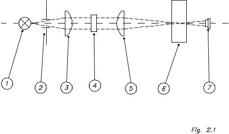
Figure 2.1. shows the optical system. It consists in:
a)An halogen lamp (1)
b)A diaphragm (2)
c)A first plano-convex lens (3)
d)An interference filter (4)
e)A second plano-convex lens (5)
f)A cuvette (6)
g)A silicon photodiode (7)
2.1.2. System description
The first component is the light source: one halogen lamp (1). The diaphragm
(2) delimits a light solid angle that is collected by the first lens (3). It sends a parallel beam to an interference filter (4). This is one of the nine possible ones located in the wheel. One stepper motor drives this wheel and, controlled by the program, place the proper filter in the optical axis, in front of the light beam. Each filter monochromes one wavelength with the characteristics described in section I.1.
A second lens (5) focuses the monochromatic beam in the cuvette center (6). In case of flow cuvettes, the light path hole itself behaves as a diaphragm, decreasing the sensitivity, that it is lower than in the common cuvettes. The
2-1
light beam goes through the cuvette as far as a light sensor (7), that converts the light beam into electric current.
2.1.3. Physical description
The optical system (figure 2.2) consists in an injected-aluminum holder (1) where there are mounted the following components:
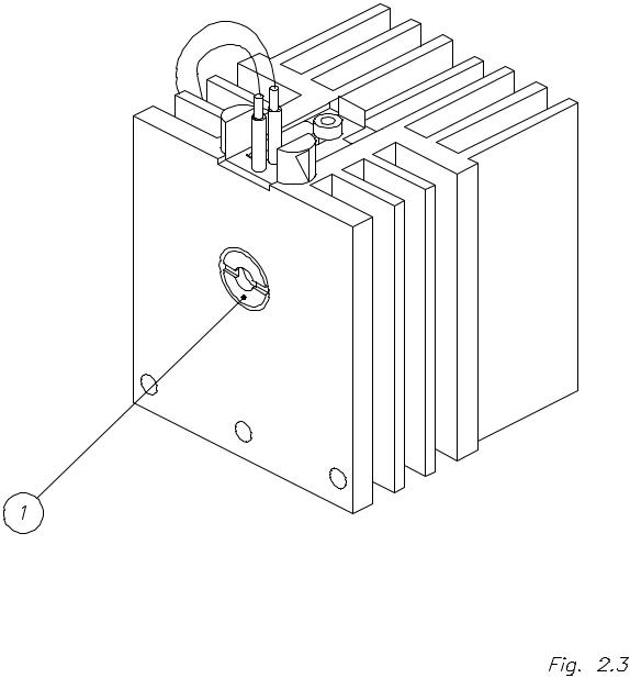
-A heat sink shape aluminium block (2) containing a lamp-holder (3). That block includes a diaphragm (figure 2.3 (1)) that delimits the a light solid angle.
-A lens holder (4) that contains the first lens.
-A filters wheel (5), with capacity for 9 filters. This filters must be mounted in special holders (6). This wheel is moved through a belt (8) by a stepper motor
(7). A photointerrupter (9) allows the detection of a stem (10) that indicates the filters wheel home position.
-A lens holder (11) that contains the second lens.
-A light protector (12), fitted together the second lens holder, avoids the parasite light interference.
-A cuvette-holder (13) holds both the cuvette and the photodiode detector. The thermostatic system is fitted together (see section 2.3.).
2.1.4. Signal conditioning
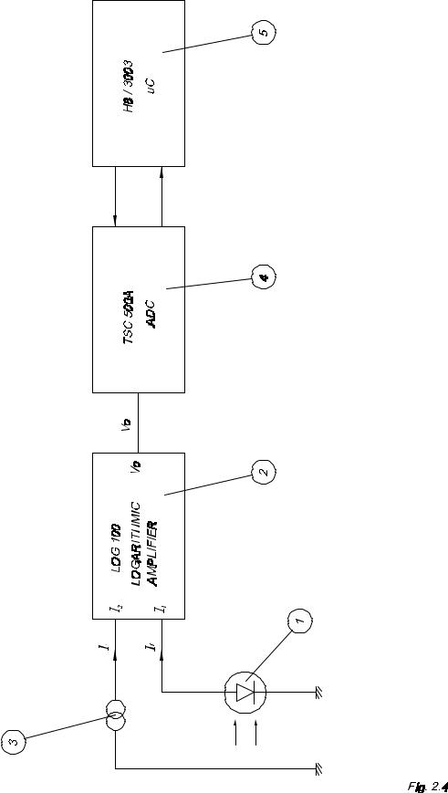
(See figure 2.4) The photodiode (1) gives an electric current (If) directly proportional to the received light. This current goes to the input I1 of the LOG100 logarithmic amplifier (2). A reference current Ir (3) (nominal 100 nA) is introduced by input I2. The output voltage of LOG-100 is:
If
V0 = k x log -----------
Ir
In this case, k=1 and V0 = 1 volt/Abs.
2-2
2-3

2-4
2-5
2-6
V0 is digitalized by the double-ramp converter TSC500A (4) with a resolution of
10,000 counts per volt. The conversion time depends on the absorbance value and increases together with it; for instance, 2 Abs time is 0.15 sec. This converter is controlled by the microcontroller (5).
2.1.5. Adjustment
The global system (optical system, amplifier and converter) is not strictly linear due to the components tolerance, so that it is necessary to do some adjustments to compensate the inherent deviations of the system.
The photometric adjustment is performed in ranges; between 0 and 2 Abs.
Several value ranges are determined and different correction factors are applied depending on the range. As deviation also depends on the wavelength, it is necessary to adjust with different filters. Adjustment process is described in section 3.2.
2.1.6. Precautions and maintenance
Maintenance of the optical system should be carried out according to the instructions given in section 5.20.
2.2. Aspiration system
2.2.1. Components
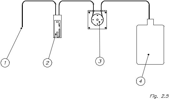
The aspiration system is composed of the following parts (figure 2.5):
a)Sipping tubing (1)
b)Flow cuvette (2)
c)Peristaltic pump (3)
d)Waste bottle (4)
2.2.2. System description
The sample is sipped by the sipping tubing (1). This tubing, Teflon made, has a standard length and the system is adjusted in accordance with it. The sipped sample enters into the flow cuvette (2), where readings take place. Sipping is performed through a silicone tube by means of a peristaltic pump (3), made up of a four-rollered rotor that is contolled by a stepper motor. Finally, the sample ends into the waste bottle (4).
2-7
2.2.3. Physical description
The sipping tubing (figures 2.6 and 2.7) is placed on the cuvette-holder tray.
The silicone tube (1), that crosses the case through a steel guiding tube (2), is fixed to this guiding tube by means of a silicone connector (3) and to the cuvette (4) by means of an inlet adapter (5). The teflon tube (6) is connected to the cuvette by an outlet adapter (7), placed in the peristaltic pump (8) and finally connected to the waste outlet (9).
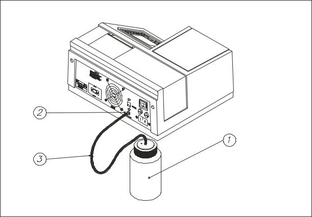
The waste bottle (1) (figure 2.8) is connected to the outlet (2) in the back of the instrument by means of a silicone tube (3).
2.2.4. Programmable parameters
Three parameters control the sipper functioning and they must be programmed to obtain the expected performance characteristics. Their programming is explained in the user’s manual.
a)SAMPLE VOLUME. It is a number that indicates the volume of sample to be sipped, in 2l.
b)PUMP DELAY. It is the number of seconds the pump will wait since the sipping finishes till the pump is activated again to position the sample into the flow cuvette.
c)POSITIONING. It is the number of steps that the peristaltic pump’s motor gives to set the sample into the flow cuvette, ensuring that it is suitably positioned in order to be read.
2.2.5. Programming
The aspiration system’s programming must be performed in order to indicate the instrument the volume, in microlitres, to be sipped.
2.2.6. Adjustment
The pump’s nominal flow is 110 2L/revolution, nevertheless, the accuracy of this figure depends on the tolerances in length and diameter of the sipping tube, that may be affected by the aging of the tube itself; this is why this value should be adjusted from time to time. The adjustment process is explained in section 3.5. As it can be also done by the user, it is also explained in the user's manual.
2-8
2.2.7. Precautions and maintenance
The general rules for the aspiration system’s maintenance are the same as the ones given in section 5.24.
Weekly adjustment of the aspiration system is strongly recommended.
2.3. Thermostatization system
2.3.1. Components
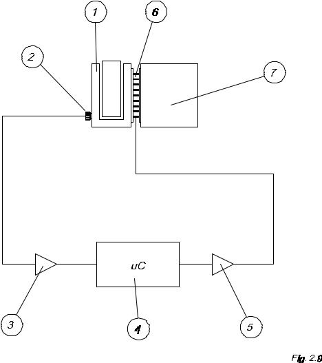
Figure 2.9 shows an schema of the thermostatization system, that is composed by the following parts:
a)A cuvette-holder (1)
b)A temperature sensor (2)
c)An amplifier of the temperature sensor (3)
d)The microcontrollers’ A/D converter (4).
e)A Peltier Cell’s in-circuit power driver(5).
f)A Peltier Cell (6)
g)A heat sink block (optical system holder) (7).
2.3.2. System description
The cuvette with the reaction mixture to be thermostatized is placed in its holder (1). Thermal contact is settled between the cuvette and the holder.
The cuvette-holder is isolated from the optical system holder (7) and contacts one of the Peltier Cell’s faces (6). The other cell’s face is in contact with the optical system holder.
The Peltier Cell pumps heat from one face to the other, depending on the current sense. The power control circuit (5) is in charge of making that current circulate in the adequate sense inside the Cell, in order to heat or cool depending on the microcontroller’s instructions.
When heating, heat is pumped from the environment (taken from the optical system holder) to the cuvette-holder and when cooling the opposite is done. The optical system holder has a heat sink block to cool the heat coming from the cuvette-holder. A temperature sensor (2) gives a small voltage, directly proportional to the cuvette-holder’s temperature, that is conditioned by one amplifier (3) and read by the microcontroller’s A/D converter (4). The microcontroller’s thermostatization program, depending on the programmed temperature and the read value, activates the power control (5) heating or cooling as required.
2-9
2-10
2-11
F ig 2 .8
2-12
2-13
2.3.3. Physical description
The cuvette-holder (13) (figure 2.2) is fixed to the optical system holder (1) by means of four screws (14) thermally isolated. The Peltier Cell (15) is located between the cuvette-holder (13) and the optical system holder (1). The temperature sensor, located in a plastic holder (16) is fixed to the cuvetteholder by a thread.
2.3.4. Programming
Programming the thermostatization system consists in indicating the instrument which temperature is desired for the reaction mixture. This value may introduced in several program’s points.
2.3.5. Adjustment
Components’ tolerance produce a deviation between the programmed temperature and the real one, so it is necessary an adjustment procedure to compensate such deviations. The thermostatization adjustment procedure is described in section 3.3.
2.3.6. Precautions and maintenance
The thermostatization system has two critical points: the good thermal contact between both faces of the Peltier Cell with the optical system holder and the cuvette-holder, and the good thermal contact between the temperature sensor and the cuvette-holder.
To ensure proper conditions in both points, the following cautions should be taken into account:
a)A thin, uniform layer of silicone must be placed in each face of the Peltier Cell, covering the whole surface.
b)The silicone layer should neither go beyond the surface of the Cell, nor go inside between its two faces; it would result in a thermal short-crossing that would reduce the system’s performance.
c)The temperature sensor should have a silicone layer in order to make a good thermal contact with the bottom of its lodging.
For assembling these components, follow the procedures described in sections
5.11. (changing the Peltier Cell) and 5.14. (changing the temperature sensor).
2-14
2.4. Communications system
This instrument is equipped with a communication channel allowing connection with computers. The operation of this communication channel depends on the program release and the computer’s application software.
2.4.1. Channel type
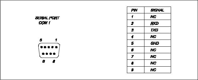
The communication channel is a RS-232, and uses the following connection lines:
RxD: Receiver Data
TxD: Transmitter Data
GND: Ground (0 volts)
The connector is located in the instrument’s back side, rounded by a box labeled COM 1. The signals’ electric level meets the E.I.A. RS-232 standard.
Figure 2.10 describes the connector’s signals.
2.4.2. Channel characteristics
The serial channel is pre-programmed by the manufacturer with next default parameters:
Baud rate: 9600
Timeout:: 0
Terminal number: 0
2.4.3. Information transmitted
The communications procedure uses a ‘sending & waiting’ protocol. Every time the transmitter sends a message, it waits for an ‘ok’ from the receiver. If the ‘ok’ message is not received, after a programmable timeout period the message is sended again. The CRC-16 error-detection code is used to check the received messages.
The communications procedure works using a MASTER-SLAVE method, so it is possible to communicate several instruments at one time. To achieve this, every instrument has to be configured with a different identification terminal number. This parameter is configured in the CONFIGURATION / COMMUNICATIONS menu.
Communications are always started by the MASTER (the computer). The
SLAVE (the instrument) is in a ‘hearing’ mode, and only sends information when it is required by the MASTER.
2-15
The instrument can send the information below:
-Quality control values
-Concentration values
In order to get the communication between the computer and the instrument, a proper computer-running software is needed. This program save the data received from the instrument into the computer hard disk. These data are stored in an EXCEL compatible format.
The file format used is showed in figure 2.11.
2.4.4. Programming
In order to get a suitable communication with a computer through the serial channel, it is necessary to fit the configuration parameters with the computer ones. If the computer parameters are not known, refer to its manual. Usually they are likewise programmable, in most cases from the application programs themselves.
The instrument can be programmed with the next parameters: transmission speed (bauds), timeout and terminal number. In the user’s manual is explained how to program these parameters.
2-16
|
- Quality control values: |
|
|
|
|
|
|
|
|
|||||
|
|
|
|
|
|
|
|
|
|
|
|
|
|
|
|
Test’s name |
|
|
|
|
|
|
|
|
|
|
|
||
|
Control 1 or Control 2 |
|
|
|
|
|
|
|
|
|
|
|
||
|
Control’s name |
|
|
|
|
|
|
|
|
|
|
|
||
|
Control’s lot |
|
|
|
|
|
|
|
|
|
|
|
||
|
Concentration |
|
Date |
|
Alarm |
|
|
|
|
|
||||
|
Concentration 1 |
|
Date 1 |
|
Alarm 1 |
|
|
|
|
|
||||
|
Concentration 2 |
|
Date 2 |
|
Alarm 2 |
|
|
|
|
|
||||
|
Concentration n |
|
Date n |
|
Alarm n |
|
|
|
|
|
||||
|
Concentration values: |
|
|
|
|
|
|
|
|
|
|
|
||
|
|
|
|
|
|
|
|
|
|
|
|
|||
|
Test’s |
Sample’s |
|
Blank |
|
Factor |
Control-1, |
Concentration |
Units |
Date |
|
|||
|
name |
number or |
|
|
|
|
|
|
Control-2 |
|
|
|
|
|
|
|
patient’s |
|
|
|
|
|
|
or sample |
|
|
|
|
|
|
|
code |
|
|
|
|
|
|
id. |
|
|
|
|
|
|
|
|
|
|
|
|
|
|
|
|
|
|
|
|
Fig.2.11
2-17
2.5. Block diagram
The block diagram (figure 2.12) is intended to give a general overview of the the electronic circuit’s different parts.
2.5.1. Logarithmic amplifier
It converts the electric current coming from the photodiode in a voltage equal to its logarithm (section 2.1.4.).
2.5.2. Analog to digital converter
It digitalizes the voltage coming from the logarithmic amplifier for its further treatment by the microcontroller.
2.5.3. Lamp control
It supplies the regulated 12V that the lamp needs to work properly.
2.5.4. Filters wheel detector
It is a photointerrupter to detect the filters wheel home position. Allows the microcontroller to know the location of each filter thus being able to position them in front of the light beam.
2.5.5. Filters wheel motor control
This is a circuit that, by means of the microcontroller’s logic control, supplies power to the stepper motor that moves the filters wheel.
2.5.6. Temperature sensor amplifier
This is a circuit to make the signal conditioning for the temperature sensor’s voltage level in order to be measured by the microcontroller’s 10-bits analog to digital converter, with a resolution enough to adjust the system.
2.5.7. Peltier cell control
This is a microcontroller-controlled power circuit that supplies the Peltier cell the adequate current to heat or cool the cell-holder.
2-18
2.5.8. Pump motor control
This is a circuit that, by means of the microcontroller’s logic control, supplies the needed power to the stepper motor that moves the peristaltic pump.
2.5.9. Keyboard circuit
This circuit basically consists in the keyboard itself and some protection diodes.
2.5.10. Printer control
It consists in the power circuits that allow the orders coming from the microcontroller to act on the printer, either moving the motors or heating the thermal head points.
2.5.11. Display circuit
This circuit consists in the display itself, the control and supply lines, one inverter circuit for the CFL backlight and one circuit to control the LCD contrast adjustment.
2.5.12. RS-232 channel circuit
It is formed by the circuits needed to make the signal conditioning from TTL voltage level to the RS-232 standard. The ACIA is integrated in the microcontroller itself.
2.5.13. Fan control
This is a circuit that measures the temperature in the power supply’s heat sink and changes the fan’s speed according to the cooling necessity. A more silent working conditions are thus achieved.
2.5.14. Microcontroller
By means of its program, it is in charge of linking and controlling almost all the instrument systems. Only the fan’s circuit and the lamp’s one are not controlled by the microcontroller.
2-19
2.5.15. Power supply
It is in charge of supplying the needed voltages to the different instrument parts.
2.5.16. Reset and battery-backup supervisory circuit
When the instrument is turned on, this circuit is in charge of keeping the microcontroller and other chips (like memories) in a ‘reset state’ until the supply voltage reaches the proper working level, avoiding undesired effects when the instrument is powered on, as well as protecting the RAM against erroneous writings during the on / off voltage transitions.
Also, this circuit provides a batery backup switchover every time the instrument is switched ON/OFF
2.6. Electronic circuit description
This section describes the different electronic parts, following the functional structure given in section 2.5.
2.6.1. Logarithmic amplifier
(See schema E33001A, sheet 1)
The logarithmic amplifier is formed by the hybrid circuit LOG-100 (U16). Its supply voltage is H 15 V. C90, C91, C96 and C97 are bypass capacitors that store electrical charge that is released to the power line whenever a transient voltage spike occurs. The photodiode is connected between ground and the input I1 (1/U16). A reference current (section 2.1.4.) is generated in the 2.5 V voltage regulator TL431CD (U15) and the T-circuit formed by R45, R51 and
R52. Its nominal value is 100 nA. The LOG-100 has the output OUT (7/U16) connected to the pin K1 (3/U16), thus being the logarithmic conversion constant (K) equal to 1. The capacitor C92 is for circuit stability.
2-20
 Loading...