


A25
SERVICE MANUAL
ENGLISH

SERVICE MANUAL
English
TESE-00001-04-ENG
June - 2006

TABLE OF CONTENTS |
|
1. INTRODUCTION ................................................................................. |
9 |
1.1. GENERAL DESCRIPTION OF THE ANALYZER ............................................................ |
9 |
1.1.1. Operating arm ...................................................................................................................................... |
10 |
1.1.2. Dispensing system ............................................................................................................................... |
10 |
1.1.3. Reactions rotor and reading ................................................................................................................ |
11 |
1.1.4. Electronic system ................................................................................................................................. |
12 |
1.1.5. Application program ........................................................................................................................... |
12 |
1.2. FUNCTIONING OF THE ANALYZER............................................................................. |
13 |
1.3. TRANSPORT AND RESHIPMENT OF THE ANALYZER .............................................. |
13 |
2. MECHANICAL COMPONENTS ........................................................ |
15 |
2.1. Instrument breakdown ................................................................................................. |
15 |
2.2. Description of the mechanical components............................................................... |
15 |
2.2.1. Operating arm ...................................................................................................................................... |
15 |
2.2.1.1. X guide .............................................................................................................................................. |
16 |
2.2.1.2. X carriage .......................................................................................................................................... |
17 |
2.2.1.3. Y carriage .......................................................................................................................................... |
18 |
2.2.1.4. Z carriage .......................................................................................................................................... |
20 |
2.2.2. Dispensing system ............................................................................................................................... |
21 |
2.2.2.1. Thermostated needle ....................................................................................................................... |
21 |
2.2.2.2. Dispensing pump .............................................................................................................................. |
22 |
2.2.2.3. Tubes and containers ....................................................................................................................... |
24 |
2.2.2.4. Container level control scales ......................................................................................................... |
25 |
2.2.2.5. Racks tray with integrated washing station ................................................................................... |
26 |
2.2.2.6. Washing pumps ................................................................................................................................ |
27 |
2.2.3. Reactions rotor with integrated optical system ................................................................................ |
27 |
2.2.3.1. Thermostated rotor and photometric system ................................................................................. |
28 |
2.2.3.2. Lighting system ................................................................................................................................. |
31 |
2.2.4. Back covers .......................................................................................................................................... |
33 |
2.2.4.1. Connectors cover .............................................................................................................................. |
33 |
2.2.4.2. Switch cover...................................................................................................................................... |
33 |
2.2.4.3. Electronics cover .............................................................................................................................. |
34 |
2.2.5. Main cover hinges ............................................................................................................................... |
35 |
2.2.6. Base ...................................................................................................................................................... |
35 |
2.2.7. Housings ............................................................................................................................................... |
36 |
3. Electronic system and fluids ......................................................... |
38 |
3.1 CPU Board (CIIM00006) ................................................................................................ |
38 |
3.2 Power Supply Board (CIIM00007) ................................................................................ |
44 |
3.3 Needle Board (CIIM00008) ............................................................................................ |
46 |
3.4 Photometry Board (CIIM00009) .................................................................................... |
47 |
3.5 Racks Board (CIIM00010).............................................................................................. |
48 |
3.6 LED Board (CIIM00011) ................................................................................................. |
48 |
3.7 Communications Board (CIIM00019) ........................................................................... |
49 |
3.8 Interconnection between boards ................................................................................. |
49 |
3.9 Boards interconnection ................................................................................................ |
54 |
3.10 Schematic liquid circuit............................................................................................... |
62 |
4. SERVICE PROGRAM ....................................................................... |
63 |
4.1 Initialising the analyser ................................................................................................. |
63 |
4.2. ADJUSTMENTS ............................................................................................................ |
65 |
4.2.1. Adjustment of the needle thermostatation system ........................................................................... |
65 |
4.2.2. Adjustment of the rotor thermostation system .................................................................................. |
66 |

Service Manual |
|
4.2.3. Adjustment of the positioning of the operating arm ........................................................................ |
67 |
4.2.3.1 Adjusting the maximum sweep of the Z axis.................................................................................. |
67 |
4.2.4. Adjustment of the positioning of the rotor ........................................................................................ |
69 |
4.2.4.1. Centering of the rotor with regard to the dispensing point .......................................................... |
69 |
4.2.4.2. Centering of the rotor with regard to the optical system.............................................................. |
69 |
4.2.5 . Adjustment of the positioning of the filter wheel ............................................................................ |
70 |
4.2.6. Adjustment of the level control scales .............................................................................................. |
71 |
4.2.7. Adjustment of the level detection sensitivity .................................................................................... |
71 |
4.3. TESTS ........................................................................................................................... |
72 |
4.3.1. Motor tests ............................................................................................................................................ |
72 |
4.3.1.1. Initialization test ............................................................................................................................... |
73 |
4.3.1.2. Movement test ................................................................................................................................... |
73 |
4.3.1.3. Loss step test ..................................................................................................................................... |
74 |
4.3.1.4. Stress mode test................................................................................................................................ |
74 |
4.3.1.5. Z axis security systems test .............................................................................................................. |
75 |
4.3.1.6 Maximum Z verification test ............................................................................................................. |
75 |
4.3.2. Diaphragm pumps and electrovalves test ......................................................................................... |
76 |
4.3.2.1. Functioning test ................................................................................................................................ |
77 |
4.3.2.2. Stress mode test................................................................................................................................ |
77 |
4.3.3. Needle self-centering system test ...................................................................................................... |
77 |
4.3.4. Needle level detection system test .................................................................................................... |
77 |
4.3.5. Needle thermostatation system test ................................................................................................... |
78 |
4.3.6. Needle rotor thermostatation system test ......................................................................................... |
79 |
4.3.7. Photometry tests .................................................................................................................................. |
80 |
4.3.7.1. Base line and integration times ...................................................................................................... |
80 |
4.3.7.2. Darkness counts ................................................................................................................................ |
82 |
4.3.7.3. Repeatability without moving the filter wheel .............................................................................. |
82 |
4.3.7.4. Stability.............................................................................................................................................. |
83 |
4.3.7.5. Repeatability moving filter wheel .................................................................................................. |
83 |
4.3.7.6. Absorbance measurement ............................................................................................................... |
84 |
4.3.7.7. Reactions rotor check....................................................................................................................... |
84 |
4.3.8. Level control scales test ..................................................................................................................... |
85 |
4.3.9. Racks and covers detection test ......................................................................................................... |
85 |
4.3.10. PC-Analyzer communications channel test .................................................................................... |
86 |
4.3.11. Global stress mode of the analyzer ................................................................................................. |
86 |
4.4. UTILITIES ...................................................................................................................... |
87 |
4.4.1. Disassembly of the dispensing needle .............................................................................................. |
87 |
4.3.2. Fluid system supply ............................................................................................................................. |
88 |
4.3.3. Cleaning of the dispensing system .................................................................................................... |
89 |
4.3.4. Changing the lamp .............................................................................................................................. |
89 |
4.3.5. Configuration of the filter wheel ........................................................................................................ |
90 |
4.3.6. Demonstration mode ........................................................................................................................... |
90 |
4.4.7 Read/load adjustments and cycles ..................................................................................................... |
91 |
4.5. REGISTER ..................................................................................................................... |
92 |
4.5.1. Introducing the analyzer serial number ............................................................................................ |
93 |
4.5.2. Service Reports.................................................................................................................................... |
93 |
4.5.3. Language change................................................................................................................................ |
94 |
4.5.4. Users...................................................................................................................................................... |
94 |
4.6. MONITOR....................................................................................................................... |
94 |
4.7 User’s program .............................................................................................................. |
95 |
4.7.1 Configuration of the level of access to the analyser ......................................................................... |
95 |
4.7.2 Reagent Consumption .......................................................................................................................... |
97 |
5. MAINTENANCE AND CLEANING..................................................... |
99 |
5.1. MAINTENANCE OPERATIONS .................................................................................... |
99 |
5.1.1. Housings and covers ........................................................................................................................... |
99 |
5.1.1.1. Removing the arm housing ............................................................................................................. |
99 |
5.1.1.2. Removing the front housing ............................................................................................................ |
99 |

5.1.1.3. Removing the main cover.............................................................................................................. |
100 |
5.1.1.4. Removing the back housing .......................................................................................................... |
101 |
5.1.1.5. Removing the main cover hinges ................................................................................................. |
102 |
5.1.2. Operating arm .................................................................................................................................... |
102 |
5.1.2.1. Fully removing the operating arm ................................................................................................ |
102 |
5.1.2.2. Changing the cable carrier chain with the electrical hoses and dispensing tube .................. |
102 |
5.1.2.3. Changing an electrical hose or the dispensing tube .................................................................. |
103 |
5.1.2.4. Changing the X motor .................................................................................................................... |
104 |
5.1.2.5. Changing the Y motor .................................................................................................................... |
104 |
5.1.2.6. Changing the Z motor..................................................................................................................... |
105 |
5.1.2.7. Changing the X motor belt ............................................................................................................ |
106 |
5.1.2.8. Changing the Y motor belt ............................................................................................................. |
107 |
5.1.2.9 Changing the Z motor belt .............................................................................................................. |
107 |
5.1.2.10. Changing the encoder-spring unit .............................................................................................. |
108 |
5.1.2.11. Changing the belt return pulleys ................................................................................................. |
108 |
5.1.2.12. Changing the X start photodetector ............................................................................................ |
109 |
5.1.2.13. Changing the Y start photodetector ............................................................................................ |
109 |
5.1.2.14. Changing the Z encoder photodetector....................................................................................... |
110 |
5.1.3. Dispensing system .............................................................................................................................. |
110 |
5.1.1.1. Removing the thermostated needle set ........................................................................................ |
110 |
5.1.3.2. Changing the needle fan ................................................................................................................ |
110 |
5.1.3.3. Changing the needle Peltier cell ................................................................................................... |
110 |
5.1.3.4. Changing the needle temperature sensor .................................................................................... |
111 |
5.1.3.5 Changing the ceramic pump ........................................................................................................... |
112 |
5.1.3.6. Changing the dispensing pump seal ............................................................................................. |
112 |
5.1.3.7. Changing the dispensing pump motor .......................................................................................... |
113 |
5.1.3.8. Changing the dispensing electrovalve .......................................................................................... |
113 |
5.1.3.9. Changing the container tube unit .................................................................................................. |
114 |
5.1.3.10. Changing the distilled water container filters ............................................................................ |
114 |
5.1.3.11. Removing the racks tray................................................................................................................ |
115 |
5.1.3.12. Changing the washing electrovalve ............................................................................................ |
115 |
5.1.3.13. Changing the washing pumps ...................................................................................................... |
116 |
5.1.3.14. Changing the load cell of the level control scales ..................................................................... |
116 |
5.1.4. Reactions rotor and reading .............................................................................................................. |
117 |
5.1.4.1. Changing the rotor temperature probe ......................................................................................... |
117 |
5.1.4.2. Fully removing the rotor ................................................................................................................. |
117 |
5.1.4.3. Changing the rotor Peltier cells ..................................................................................................... |
118 |
5.1.4.4. Changing the rotor cover detector ................................................................................................. |
119 |
5.1.4.5. Changing the rotor start photodetector ......................................................................................... |
119 |
5.1.4.6. Changing the rotor motor .............................................................................................................. |
120 |
5.1.4.7. Changing the rotor belt .................................................................................................................. |
120 |
5.1.4.8. Changing the lamp ......................................................................................................................... |
121 |
5.1.4.9. Changing an optical filter .............................................................................................................. |
121 |
5.1.4.10. Configuration of the filter wheel ................................................................................................. |
122 |
5.1.4.11. Changing the filter wheel start photodetector ........................................................................... |
123 |
5.1.4.12. Changing the filter wheel motor ................................................................................................. |
123 |
5.1.4.13. Changing the lenses ..................................................................................................................... |
123 |
5.1.4.14. Changing the optical fan.............................................................................................................. |
124 |
5.1.5. Electronic Systems ............................................................................................................................ |
124 |
5.1.5.1. Changing the microprocessor board ............................................................................................ |
125 |
5.1.5.2. Changing the power supply board ............................................................................................... |
125 |
5.1.5.3. Changing the needle conditioning board .................................................................................... |
125 |
5.1.5.4. Changing the racks detection board ............................................................................................ |
126 |
5.1.5.5. Changing the photometric system board ..................................................................................... |
127 |
5.1.5.6. Changing the front indicator board .............................................................................................. |
128 |
5.1.5.7. Change the communications board ............................................................................................. |
128 |
5.1.5.8.Changing the firmware program ................................................................................................... |
128 |
5.2. RECOMMENDED PREVENTIVE MAINTENANCE .................................................... |
128 |
5.3. CARE AND CLEANING ............................................................................................... |
129 |

Service Manual |
|
5.3.1. General care of the analyzer ........................................................................................................... |
129 |
5.3.2. Cleaning the optical system ............................................................................................................. |
129 |
5.3.3. Cleaning the dispensing system ...................................................................................................... |
130 |
5.3.4. General cleaning of the interior of the apparatus ......................................................................... |
130 |
AI. TECHNICAL SPECIFICATIONS ................................................... |
131 |
A II. ADJUSTMENT MARGINS TABLES ............................................ |
135 |
A III. LIST OF CONSUMABLES, ACCESSORIES AND SPARES ....... |
136 |
A IV. LIST OF REQUIRED TOOLS ..................................................... |
141 |
A V. SOFTWARE VERSIONS ............................................................. |
142 |
1. INTRODUCTION
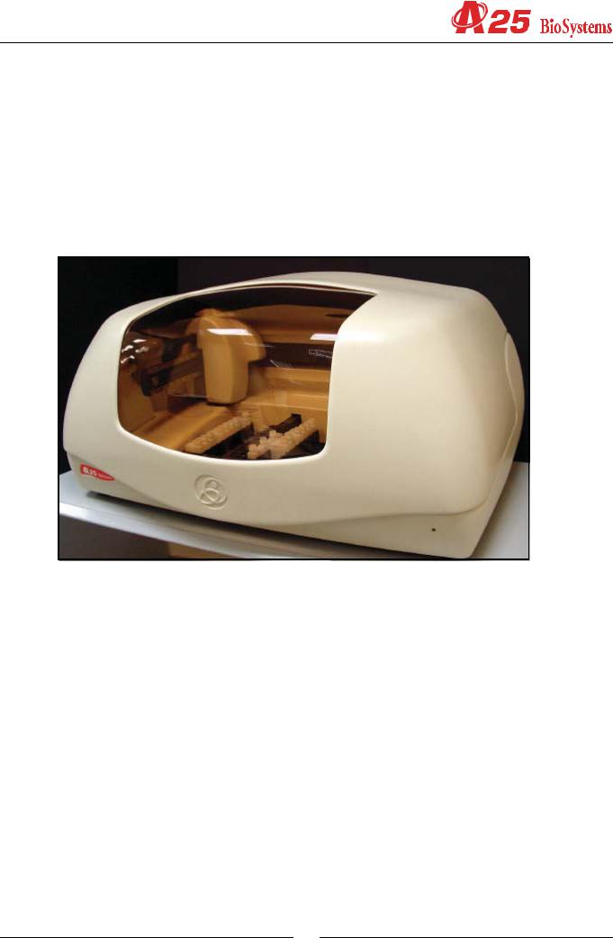
The A25 analyzer is an automatic random access analyzer specially designed for performing biochemical and turbidimetric clinical analyses. The instrument is controlled on-line in real time from an external dedicated PC.
In each of the components of the A25 analyzer, BioSystems has used leading edge technology to obtain optimum analytical performance, as well as taking into account economy, robustness, easy use and maintenance. A three-axis Cartesian operating arm prepares the reactions. Dispensing is performed by means of a pump with a ceramic piston via a detachable thermostatised needle with Fuzzy Logic control. A washing station guarantees that the needle is kept perfectly clean throughout the process. The reactions take place in a thermostatised rotor in which absorbance readings are taken directly by means of an integrated optical system.
This manual contains the information required for learning about, maintaining and repairing the A25 automatic analyzer. It should be used by the Technical Service as a learning and consultation document for the maintenance and repair of the instrument. Chapter 2 describes the different mechanical components that form the analyzer together with their functionality, and chapter 3 describes the electronic system. Chapter 4 describes the Service Program. All the adjustments and checks of the analyzer are carried out through this program, which is independent from the application program (User Program). The separation of both programs enable it to be maintained separately and the extensions and improvements of one do not affect the other. The user does not have the service program. The Technical Service must install it on the user’s computer in order to carry out the service requirements. Once said tasks have been carried out, the Technical Service must uninstall the program. Chapter 5 offers instructions for the different maintenance, repair and cleaning operations that can be carried out by the Technical Service. The annexes contain a summary of the technical specifications of the analyzer, the adjustment margin tables, the lists of accessories and spares, a list of software versions and their compatibility and a software troubleshooting guide.
1.1. GENERAL DESCRIPTION OF THE ANALYZER
The A25 analyzer is made up of three basic components: the operating arm, the dispensing system and the reading and reactions rotor. The electronic system of the instrument controls said components and communicates with the external
9
Service manual
computer containing the application program. Through this program, the user can control all the operations of the analyzer. The analyzer may be fitted with the option of an external module for measuring ion concentration.
1.1.1. Operating arm
This is a three-axis XYZ Cartesian mechanism. The X and Y axes move the dispensing needle over the analyzer horizontally and the Z axis moves it vertically. It is operated by three step-by-step motors. In each 15-second preparation cycle, the operating arm performs the following actions: first of all, it sucks in the reagent from the corresponding bottle. Next, the needle is washed externally in the washing station and sucks in the sample from the corresponding tube. It is washed externally again and dispenses the sample and the reagent into the reactions rotor. Finally, it is exhaustively washed internally and externally before proceeding with the next preparation. The arm has a system for controlling vertical movement to detect whether or not the needle has collided into anything on descending. If a collision occurs, as may be the case if, for example, a lid has been left on a bottle of reagent, the arm automatically restarts, verifies the straightness of the needle and continues working issuing the corresponding alert to the user. A vertical axis retention system prevents the needle from falling in the case of a power cut, avoiding injury from the needle to the user or the needle being bent by an attempt to move the arm manually. The operating arm only makes the preparations if the general cover of the analyzer is closed. If the cover is raised while it is functioning, the arm automatically aborts the task in progress and returns to its parked position to avoid injury to the user.
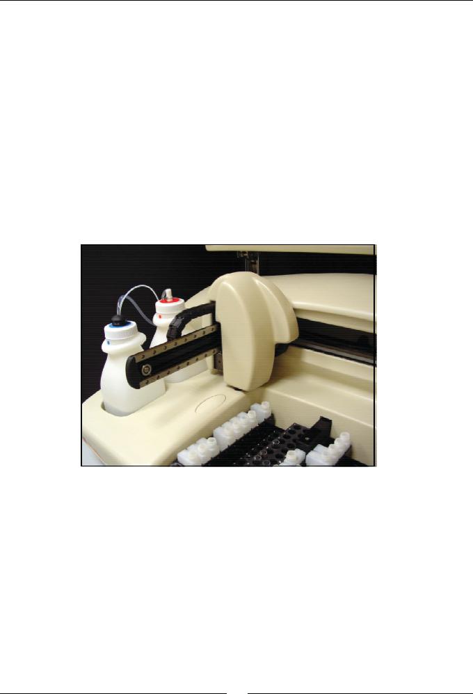
1.1.2. Dispensing system
This system consists of a thermostatised needle, supported and displaced by an operating arm and connected to a dispensing pump. The needle is detachable to enable cleaning and replacement. The analyzer has capacity level detection to control the level of the bottles and tubes and prevent the needle from penetrating too far into the corresponding liquids, thus minimising contamination. An automatic adjustment system informs the user if the needle is not mounted or if it is too bent. The needle has a sophisticated Peltier thermostatisation system, with Fuzzy Logic control, capable of thermostatising the preparations at approximately 37º in less than 6 seconds. Dispensing is carried out by means of a low maintenance ceramic piston pump driven by a step-by-step motor. It is capable of dispensing between 3 and 1250 L. The exterior of the needle is kept constantly clean by means of a washing station, which consists of a font specially designed to clean and dry the needle, integrated in the racks tray. A system of diaphragm pumps supplies the font with distilled water and transports the waste to its container.
The A25 analyzer has a tray with 6 free positions for racks of reagents or samples, plus three fixed positions for bottles opposite the washing station. Each reagents rack can carry up to 10 reagents in 20 ml or 50 ml bottles. Each samples rack can contain up to 24 tubes of samples. The samples can be patients, calibrators or controls. The analyzer can be configured to work with 13 mm or 15 mm diameter tubes of samples with a length of up to 100 mm or with paediatric wells. Any possible configuration of racks can be mounted from 1 rack of reagents (10 reagents) and 5 racks of samples
10
(120 samples) to 5 racks of reagents (50 reagents) and 1 rack of samples (24 samples). Any reagent may be placed in the fixed positions, but it is recommendable to use them for the bottles of distilled water, saline solution for the automatic pre-dilutions and washing solution. The rack tray detects and identifies the type of racks. In this way, if the physical disposition of the racks does not coincide with that programd on the computer, the analyzer alerts the user.
On the left of the analyzer are the waste and distilled water containers. The analyzer constantly controls the level of these containers and issues the appropriate alerts if the distilled water is nearly empty or if the waste container is full.
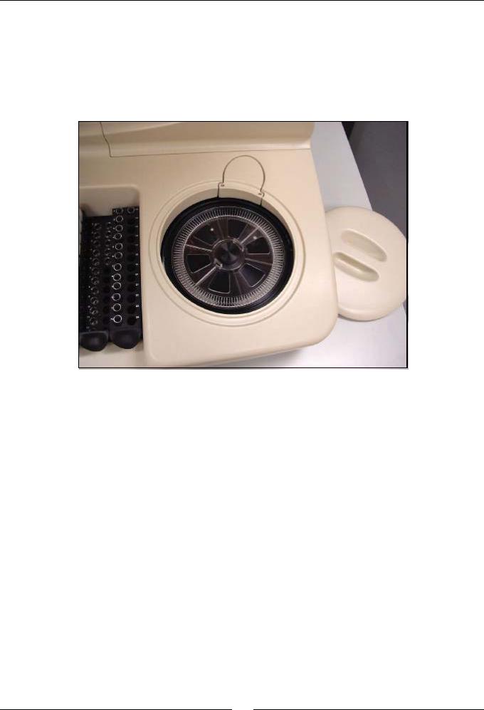
1.1.3. Reactions rotor and reading
The preparations are dispensed in an optical quality methacrylate reactions rotor thermostatised at 37ºC. The optical absorbance readings are taken directly on this rotor. Each reaction can be read for 15 minutes. The readings are taken as they are programd in each measurement procedure. The reaction wells have been designed to enable the mixture of the sample and the reagent during the dispensing. Each rotor has 120 reaction wells. The length of the light path is 6 mm. The minimum volume required to take the optical reading is 200 L. The wells have a maximum useful capacity of 800 L. When the reactions rotor is completely full, the user must change it with one that is empty, clean and dry. The reactions rotors can be reused up to 5 times if they are carefully cleaned immediately after use. The Cleaning the semi-disposable reactions rotor section in the User’s Manual describes how to clean the rotors. The user has a test in the computer program, which he or she may use to check the condition of the rotor. The rotor is driven by a step-by-step motor with a transmission. A Peltier system with PID control thermostatises the rotor at 37ºC.
An optical system integrated in the rotor takes the readings directly on the reaction wells. The light source is a 20 W halogen lamp. The detector is a silicon photodiode. The wavelength is selected by a wheel with 9 positions available for optic filters. The filters are easily changed by the user from the exterior of the analyzer, without the need for disassembling the filter wheel. A step-by-step motor positions the wheel. The optical system is capable of taking 5 readings per second, with or without a filter change in between. The light beam of the lamp passes through a compensated interferential filter to select the desired wavelength and through focalisation lenses. It then passes through the rotor well and finally reaches the photodiode, where the light signal is turned into an electric signal. A sophisticated analogical digital integratorconverter system converts the electric signal into a digital value with which the analyzer obtains the absorbance values.
11
Service manual
The optical system continues to work when the general cover of the analyzer is open, whereby the analyzer can continue to take readings while the user handles, for example, the sample tubes or the reagent bottles. The rotor cover must be in place for the optical system to work correctly. A detector tells the analyzer of the presence of the cover. The analyzer aborts the readings if the user removes the rotor cover while the optical system is taking photometric measurements. If the rotor is not covered, the analyzer informs the user so that he or she places the rotor cover when it sends samples to be analyzed.
1.1.4. Electronic system
The described components are controlled by an electronic system based on a microprocessor. The microprocessor has two external communication channels that make it possible to link up the instrument to the computer containing the application program and to an optional external module for measuring ion concentration. The electronic system is made up of the following independent boards:
-Microprocessor board
-Photometric system board
-Needle conditioning board
-Racks detection board
-Front indicator board
-Power supply board
-Communications board
1.1.5. Application program
The application program makes it possible to control all the operations of the analyzer. From this program, the user can monitor the state of the analyzer and the work session, program parameters, e.g. technique parameters, prepare the work session, prepare results reports, configure different analyzer options, activate various test utilities, prepare and maintain the instrument and carry out internal quality control processes. The purpose of this manual is not to explain the functioning of the user program. For detailed information to this regard, please consult the User’s Manual included with the analyzer.
12

1.2. FUNCTIONING OF THE ANALYZER
The A25 analyzer is an automatic random access analyzer specially designed for performing biochemical and turbidimetric clinical analyses. The analyzer performs patient-by-patient analyses and enables the continual introduction of samples. The analyzer is controlled from a dedicated PC that is permanently communicated to the instrument. The program, installed on the computer, keeps the user constantly informed of the status of the analyzer and the progress of the analyses. As results are obtained, the computer shows them to the user immediately.
When a Work Session is begun, the analyzer proposes performing the blanks, calibrators and controls programd for the measurement procedures it is to carry out. The user may choose between performing the blanks and the calibrators or not. If they are not performed, the analyzer uses the last available memorised data. The controls can also be activated or not. During a session, while the analyzer is working, the user can introduce new normal or urgent samples to be analyzed. Each time a new sample is added, the analyzer automatically proposes the possible new blanks, calibrators or controls to be performed. A work session can remain open for one or more days. When a session is closed and another new session is opened (Reset Session), the analyzer again proposes performing the blanks, calibrators and controls. It is recommended that the session is reset each working day.
The analyzer determines the concentrations of the analytes based on optical absorbance measurements. To measure the concentration of a certain analyte in a sample, the analyzer uses a pipette to take a specific volume of the sample and the corresponding reagent, quickly thermostatises them in the needle itself and dispenses them into the reactions rotor. The very dispensing speed together with the geometry of the reaction well causes the mixture to be shaken and the chemical reaction begins. In the bireagent modes, the reaction begins when the analyzer later dispenses a second reagent in the same reaction well. The reactions can be biochemical or turbidimetric. In both cases, the reaction or the chain of reactions produced generate substances that attenuate certain wavelengths, either by absorption or by dispersion. Comparing the light intensity of a certain wavelength that crosses a well when there is a reaction and when there is not a reaction can determine the concentration of the corresponding analyte. This comparison is quantified with the physical magnitude called absorbance. In some cases, the concentration is a direct function of the absorbance, and in other cases, it is a function of the variation of the absorbance over time, depending on the analysis mode.
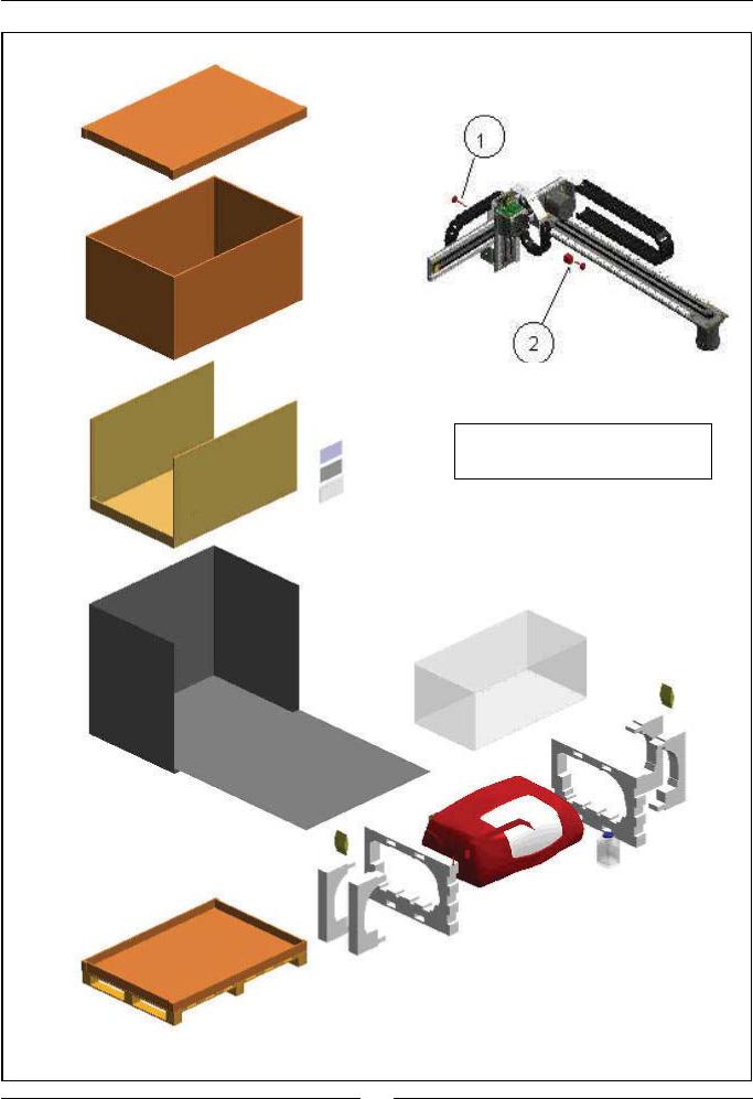
1.3. TRANSPORT AND RESHIPMENT OF THE ANALYZER
If the analyzer is to be reshipped or moved using a transport vehicle, it is important to block the operating arm and use the original packaging to ensure that the apparatus is not damaged. To package the instrument, we recommend you follow the following instructions: (on the unpackaging instructions sheet).
13
Service manual
Screws (1) and (2) are for blocking and unblocking the arm mechanism.
14

2. MECHANICAL COMPONENTS
2.1. Instrument breakdown
The physical structure of the analyzer can be broken down as follows:
·Operating arm
-X guide.
-X carriage.
-Y carriage. This includes the spring and encoder of the Z carriage.
-Z carriage. This is the carriage carrying the thermostated needle. It includes the electronic needle conditioning board.
-Cable carrier chains. These contain the electrical hoses of the arm and the dispensing tube.
·Dispensing system.
-Thermostated probe.
-Dispensing pump.
-Tubes and containers.
-Container level control scales.
-Racks tray with integrated washing station. This includes the electronic racks detection board.
-Washing pumps.
·Reactions rotor with integrated optical system.
-Thermostated rotor and photometric system. This contains the electronic photometric system board.
-Lighting system.
·Back covers
·Main cover hinges.
·Base. This houses the electronic boards of the microprocessor, the power supply and the front indicator.
·Housings.
-Back housing.
-Front housing. This houses the optical and rotor covers.
-Arm housing.
-Main cover.
The following is a brief description of each of the mechanical components that make up the analyzer.
2.2. Description of the mechanical components
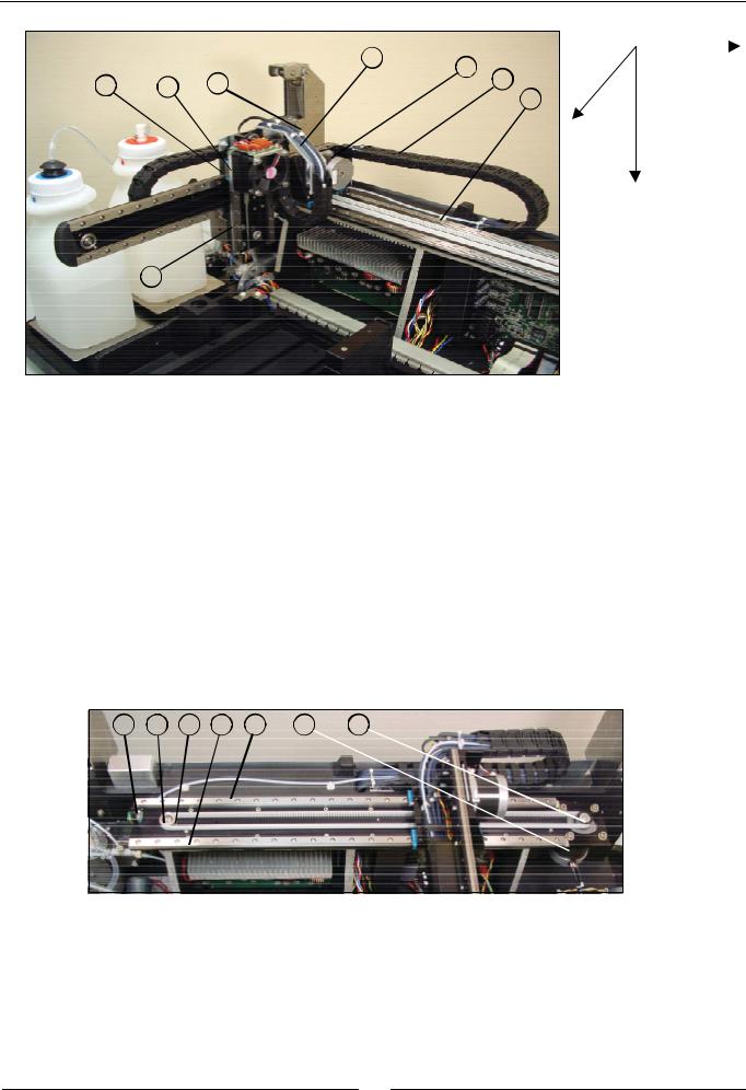
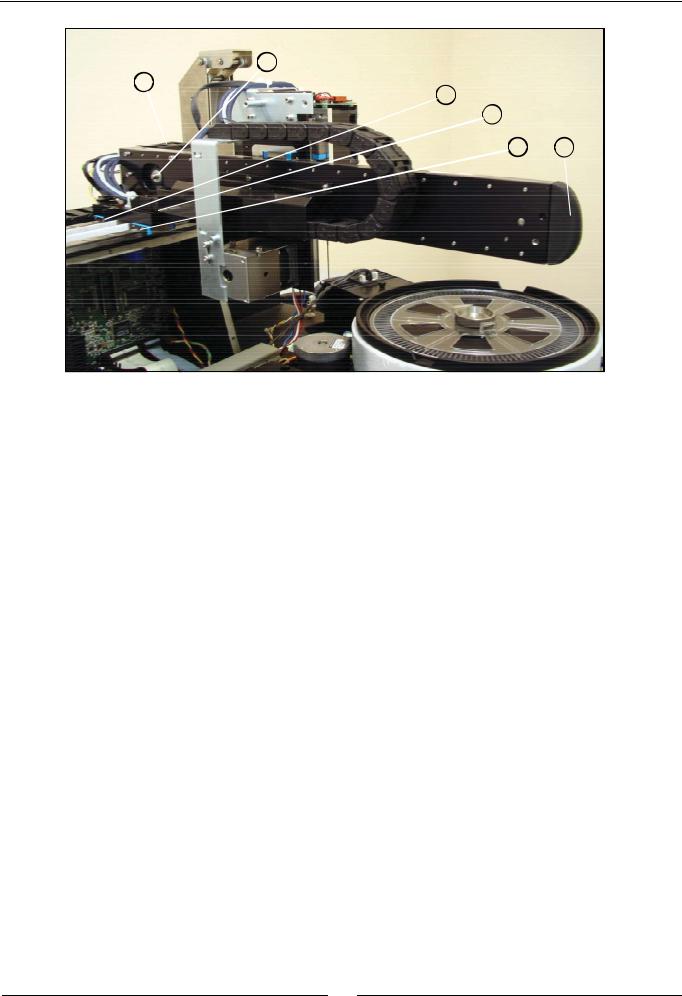
2.2.1. Operating arm
This mechanism positions the dispensing needle appropriately during the preparation of the analyses. An encoder checks the vertical movement of the needle and a spring automatically stops it from falling in the case of a power cut. The dispensing tube and the electrical hoses of the arm are housed in cable carrier chains, which guide them appropriately. A housing unit covers the Y and Z carriages.
(1)X GUIDE
(2)X CARRIAGE
(3)Y CARRIAGE
(4)Z CARRIAGE
(5)CABLE CARRIER CHAIN
(6)TEFLON DISPENSING TUBE
(7)ELECTRICAL HOSES
(8)Y CARRIAGE CHAIN SUPPORT COVER
15
Service manual
|
|
7 |
2 |
5 |
|
X |
8 |
4 |
6 |
|
|||
|
1 |
|
||||
|
|
|
|
|
|
Y
Z
3
The Z carriage (4) supports the thermostated needle and can be displaced over the Y carriage (3), which, in turn, can be displaced over the X carriage (2), which, in turn, can be displaced over the X guide (1). In this way, the needle can be displaced in the three Cartesian directions of X, Y and Z. The cable carrier chain (5) houses the Teflon dispensing tube (6) and all the electrical hoses (7) of the arm. The support cover (8) guides the cable carrier chain of the Y carriage along the X carriage.
2.2.1.1. X guide
(1)X GUIDE PROFILE
(2)X TRACK RAILS
(3)X START PHOTODETECTOR
(4)RETURN PULLEY
(5)BEARING
(6)OPERATING PULLEY
(7)X MOTOR
3 |
4 |
5 |
2 |
1 |
7 |
6 |
This consists of an aluminium profile (1) which holds the steel rails (2) on which the X carriage runs. The photodetector
(3) indicates the position of the start of the movement of the X carriage. The motor (7) operates the belt of the X carriage by means of the pulley (6). The pulley (4), fitted on the bearing (5), returns the belt operated by the motor.
16
2.2.1.2. X carriage
(1)X CARRIAGE BODY
(2)Y GUIDE PROFILE
(3)Y TRACK RAILS
(4)Y START PHOTODETECTOR
(5)X START DETECTION BARRIER
(6)LINEAR SLIDE UNIT
(7)NOTCHED BELT
(8)BELT FASTENING
(9)RETURN PULLEY
(10)BEARING
(11)OPERATING PULLEY
(12)Y MOTOR
(13)X CARRIAGE CHAIN SUPPORT COVER
(14)X CARRIAGE CHAIN TERMINAL
(15)Y CARRIAGE CHAIN TERMINAL
(16)Y GUIDE RUBBER PROTECTION
4
3
10
9 2
8 |
12 |
13 |
|
7 |
|
|
|
1
17
Service manual
11
14
5
15
6 17
The X carriage can run over the X guide. The body of the X carriage (1) supports the aluminium profile (2) that holds the steel rails (3) on which the Y carriage runs. The photodetector (4) indicates the start position of the movement of the Y carriage. The motor (12) operates the Y carriage belt by means of the pulley (11). The pulley (9), fitted on the bearing (10), returns the belt operated by the motor. The barrier (5) obstructs the X start photodetector when the X carriage reaches its start position. The X carriage runs on its guide using the linear slide unit (6) fastened to the carriage body. The belt (7) operates the X carriage. It is held to the body of the X carriage by means of the fastening (8). The support (13) holds the terminal of the X carriage chain (14). The Y carriage chain terminal (15) is screwed directly onto the X carriage. The rubber protection (16) prevents the Y guide from injuring the user.
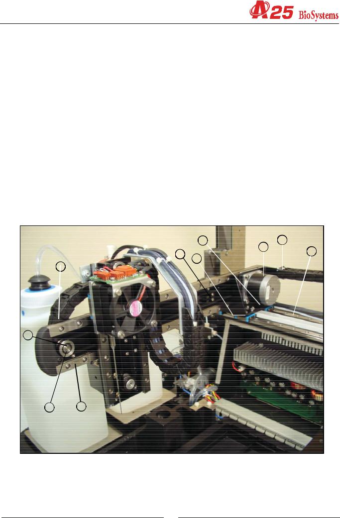
2.2.1.3. Y carriage
(1)Z GUIDE PROFILE
(2)Z TRACK RAILS
(3)Y START DETECTION BARRIER
(4)Z START DETECTION BARRIER
(5)LINEAR SLIDE UNIT
(6)Y CARRIAGE CHAIN TERMINAL
(7)Z CARRIAGE CHAIN TERMINAL
(8)NOTCHED BELT
(9)BELT FASTENING
(10)RETURN PULLEY
(11)BEARING
(12)OPERATING PULLEY
(13)Y CARRIAGE CHAIN SUPPORT COVER
(14)ENCODER PHOTODETECTOR
(15)ENCODER
(16)SPRING
(17)SPRING FASTENING
(18)SUPPORT BODY
(19)COVER
(20)BONDING STRIP
(21)UNIT HOLDING
(22)Z MOTOR
18

2 |
11 |
4 |
10 |
3 |
1 |
7 |
9
8
12 
5
17 16
7
13
20
14
17
22
15
18
19
 21
21
19
Service manual
The Y carriage can run on the Y guide, which forms part of the X carriage. The aluminium profile (1), which holds the steel rails (2) on which the Z carriage runs, constitutes the body of the Y carriage itself. The motor (22) operates the Z carriage belt through the pulley (13). The pulley (11), fitted on the bearing (12), returns the belt operated by the motor. The barrier
(3) obstructs the X start photodetector when the X carriage reaches its start position. The barrier (4) obstructs the Z start photodetector when the Z carriage reaches its start position. The Y carriage runs on its guide using the linear slide unit
(5) fastened to the carriage body. The belt (9) operates the Y carriage. It is held to the body of the Y carriage by means of the fastening (10). The support (14) holds the Y and Z carriage chain terminals (7) and the arm housing. The springencoder unit of the Z carriage is made up of components (15)-(22). Part (19) is made up of the system body and contains the self-raising spring (17) and the encoder (16) for the detection of vertical collisions. Part (18) joins the spring to the encoder. The photodetector (15) detects the turn of the encoder when it runs along the Z carriage. The cover (20) closes the system. The motor (23) has two shafts. Its back shaft has the encoder (16) and its front shaft has the operating pulley of the Z carriage (13). Part (22) holds the system body (19) to the motor. The board (21) joins the system to the instrument frame.
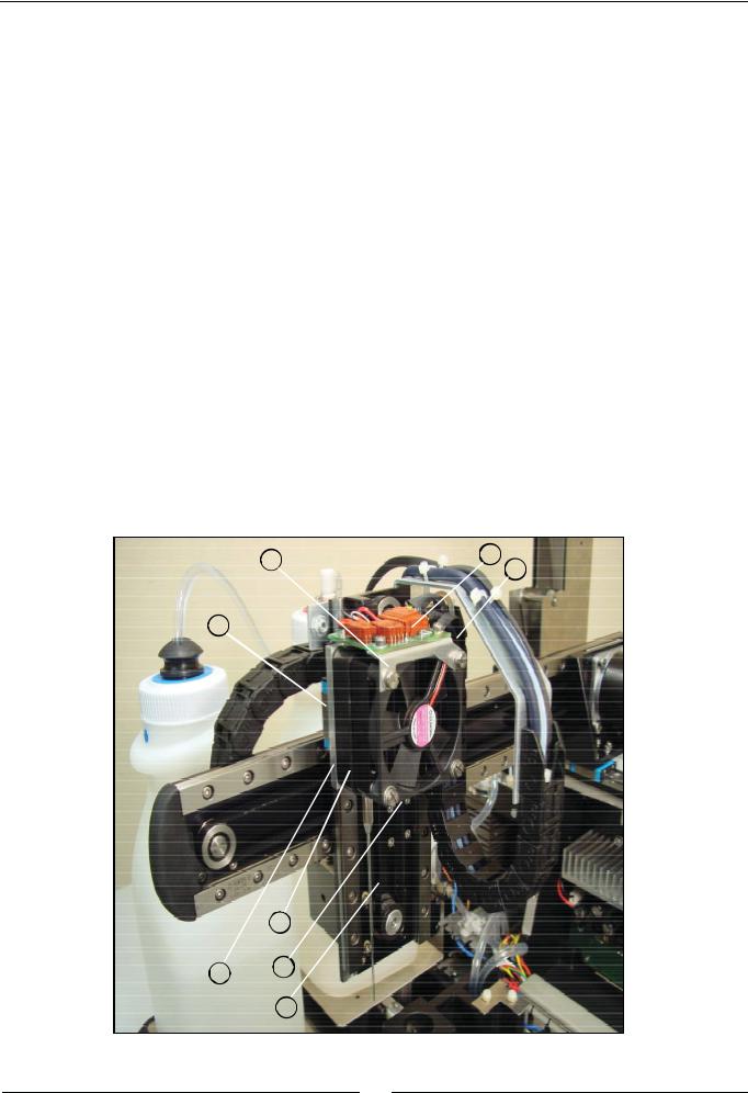
2.2.1.4. Z carriage
(1)ELECTRONIC NEEDLE CONDITIONING BOARD
(2)BOARD SUPPORT
(3)LINEAR SLIDE UNIT
(4)Z CARRIAGE CHAIN TERMINAL
(5)Z CARRIAGE BODY
(6)GEARED BELT
(7)BELT FASTENING
(8)THERMOSTATED NEEDLE
2 |
1 |
|
4 |
||
|
3
8
57
6
20
The Z carriage holds the thermostated needle (9). It can run along the Z guide, which forms part of the Y carriage, by means of the guide rollers (3) fastened to the carriage body (6). The belt (7) that operates the Z carriage is held to the body of the carriage by means of the fastening (8). The terminal of the Z carriage chain (5) is screwed to the carriage body. The electronic needle conditioning board (1) is screwed to the needle body and to the support plate (2). This board contains the Z carriage start photodetector.
2.2.2. Dispensing system
The dispensing pump dispenses the preparations through the thermostated needle. The needle is washed internally and externally at the washing station. The racks tray makes it possible to position the samples to be analyzed and the required reagents. The level of the distilled water and waste containers is controlled by the analyzer by weight.
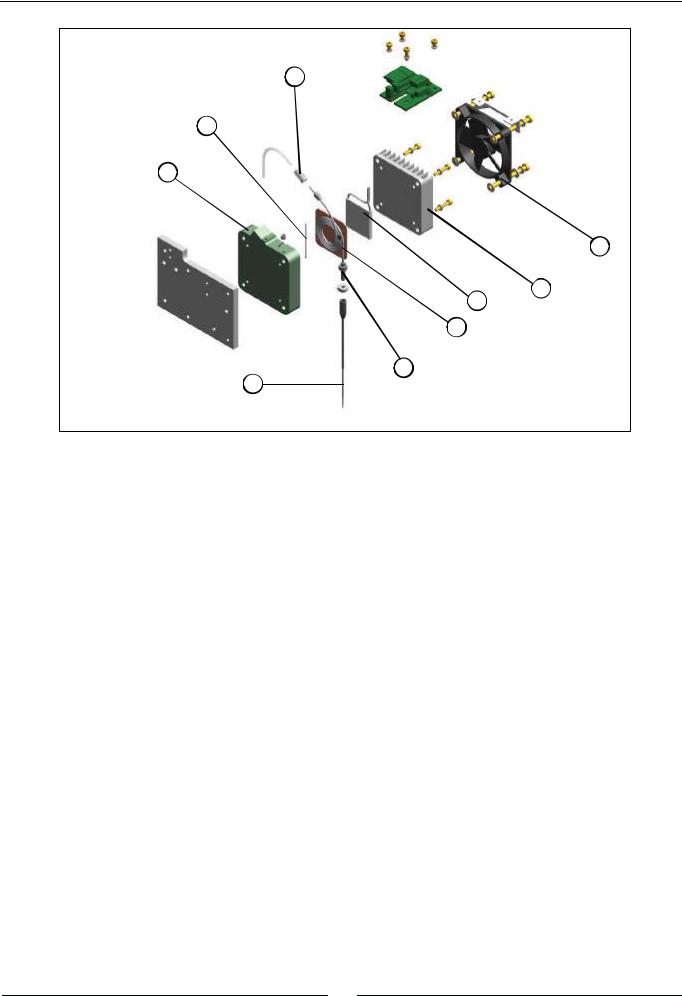
2.2.2.1. Thermostated needle
(1)PELTIER CELL
(2)THERMISTOR
(3)SPIRAL UNIT
(4)NEEDLE FASTENING FITTING
(5)REMOVABLE NEEDLE
(6)BODY
(7)FASTENING FITTING
(8)RADIATOR
(9)FAN
7
9
6
8
5
21
Service manual
7
2
6
9
8
1
3
4
5
The spiral unit (3) is made up of a spiral tube with fittings at both ends, welded to a copper plate. This unit is housed in the interior of the plastic body (6). The thermistor (2) is held between these two parts and is the sensor used to control the system temperature. The lower end of the tube of the spiral unit is firmly fastened to the body by the nut (4). The removable needle (5) is screwed to this end of the tube. The upper end of the spiral tube is connected to the Teflon dispensing tube of the operating arm. The fastening fitting (7) ensures said connection. The Peltier cell (1) that controls the temperature is in contact with the copper plate of the spiral unit. The radiator (8), which is screwed to the plastic body, closes the system. The bolts that hold the radiator fan (9) are bushing bolts and are used to fasten the entire needle unit to the Z carriage of the operating arm.
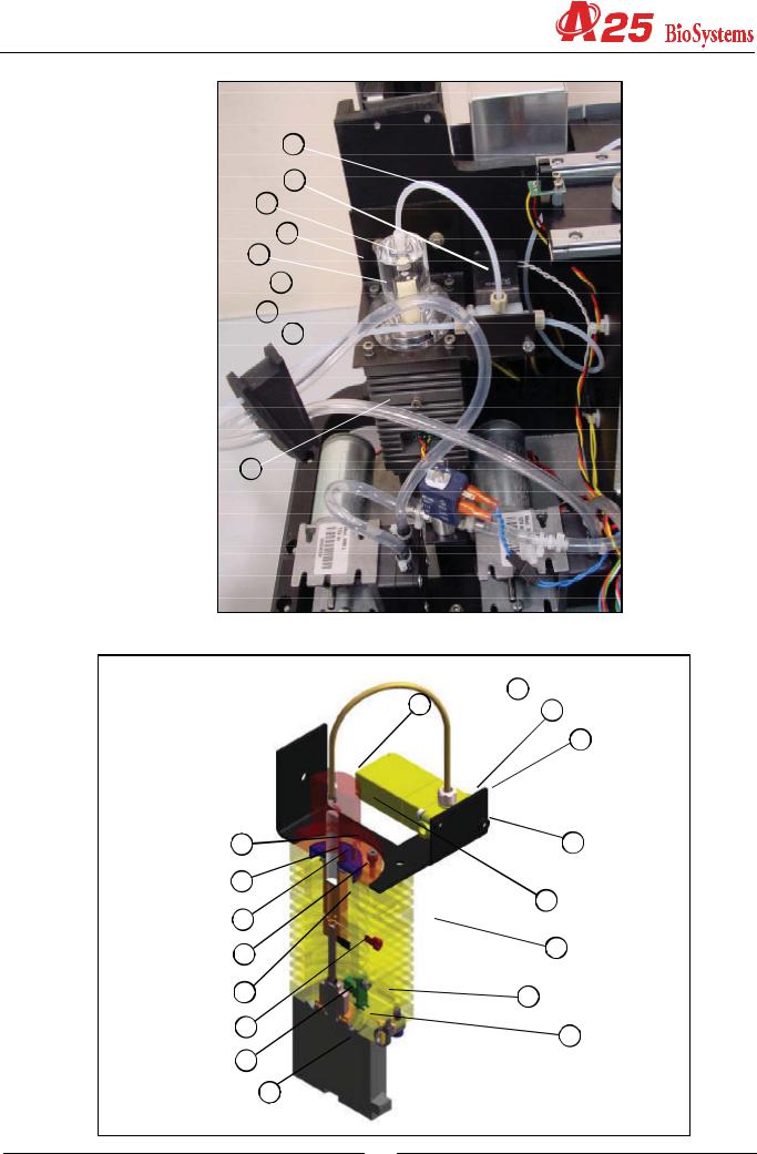
2.2.2.2. Dispensing pump
(1)BODY
(2)FLUIDIC CHAMBER
(3)SEAL
(4)SEAL SUPPORT
(5)CERAMIC PISTON
(6)PISTON SUPPORT
(7)TRANSMISSION PROTECTOR
(8)START DETECTION BARRIER
(9)WORM
(10)AXIAL BEARING
(11)MOTOR
(12)START PHOTODETECTOR
(13)PUMP SUPPORT
(14)PUMP FITTING
(15)PUMP-ELECTROVALVE TEFLON TUBE
(16)3-CHANNEL ELECTROVALVE
(17)ELECTROVALVE FITTING
22
15
16
14
13
2
17
5 
3 
1
 15
15
14 |
17 |
|
16
5 |
13 |
4 |
|
3 |
2 |
|
|
7 |
1 |
|
|
6 |
12 |
8 |
10 |
|
|
9 |
|
|
11 |
23
Service manual
The aluminium body (1) joins the different components that make up the pump. The transparent methacrylate fluidic chamber (2) makes it possible to observe the flow of liquid through the pump. The support (4) fastens the seal (3) to the chamber. The ceramic piston (5) dispenses by displacing a certain volume of liquid in the chamber. The plastic protection
(7) prevents the pump transmission from getting wet if the seal fails. The piston is adhered to the support (6), which moves alternatively by the rotation of the worm (9) fixed to the motor shaft (11). The barrier (9), joined to the piston support, obstructs the photodetector (12) when the piston reaches its start position. The axial bearing (10) prevents any longitudinal displacement of the motor shaft for greater precision in the dispensing operation. The 3-channel electrovalve (16) makes it possible to connect the pump chamber to the distilled water container or to the thermostated needle. The support (13) makes it possible to fasten the pump and the electrovalve to the analyzer. The Teflon tube (15) connects the chamber to the electrovalve. It is connected to each of these components by the fittings (14) and (17).
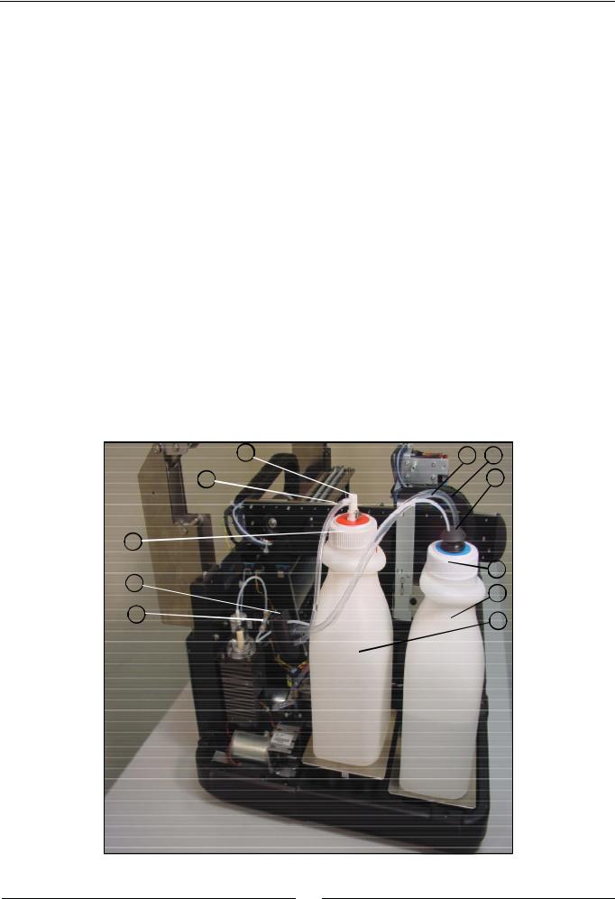
2.2.2.3. Tubes and containers
(1)WATER CONTAINER
(2)WATER CONTAINER LID
(3)WATER CONTAINER TUBES FASTENING
(4)WATER CONTAINER TEFLON TUBE
(5)TEFLON TUBE FILTER
(6)ELECTROVALVE FITTING
(7)WATER CONTAINER PVC TUBE
(8)PVC TUBE FILTER
(9)WASTE CONTAINER
(10)WASTE CONTAINER LID
(11)FAST COUPLING FITTING
(12)WASTE CONTAINER PVC TUBE
(13)GROMMET
11 4 7
12 |
3 |
|
10 |
|
|
13 |
2 |
|
1 |
||
|
||
6 |
9 |
|
|
24
5
8
The Teflon tube (4) connects the distilled water container (1) to the electrovalve of the dispensing pump. This tube is installed at the end of the filter container (5). It is connected to the electrovalve of the dispensing pump through the fitting
(6) The PVC tube (7) connects the distilled water container to the diaphragm pump of the washing water. This tube is installed at the end of the filter container (8). Both water tubes pass through the rubber piece (3) in the lid (2) of the container, which fastens them in position. The PVC tube (12) connects the waste extraction diaphragm pump to the waste container (9). The waste container lid (10) has a fast coupling fitting (11) with automatic drip-proof closing when disconnected. All the tubes pass into the interior of the analyzer through the rubber grommet (13).
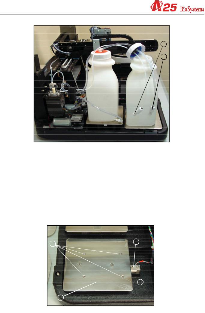
2.2.2.4. Container level control scales
(1)LOAD CELL
(2)BASE SUPPORT
(3)BASE
(4)ADJUSTABLE MAXIMUMS
4 |
1 |
|
 2
2
3
25
Service manual
The analyzer has two scales to control the level of the distilled water and waste containers by weight. Each of these scales has a load cell (1) as a weighing component. One of the ends of the cell is fastened to the base of the instrument. The support of the base (2) is screwed to the other free end. The base (3) is the stainless steel board on which the containers stand. The base of the analyzer has 4 adjustable maximums (4) for regulating the maximum allowed deformation of the load cell. The maximums prevent the cells from deteriorating if the user puts the containers on the scales in a brusque manner.
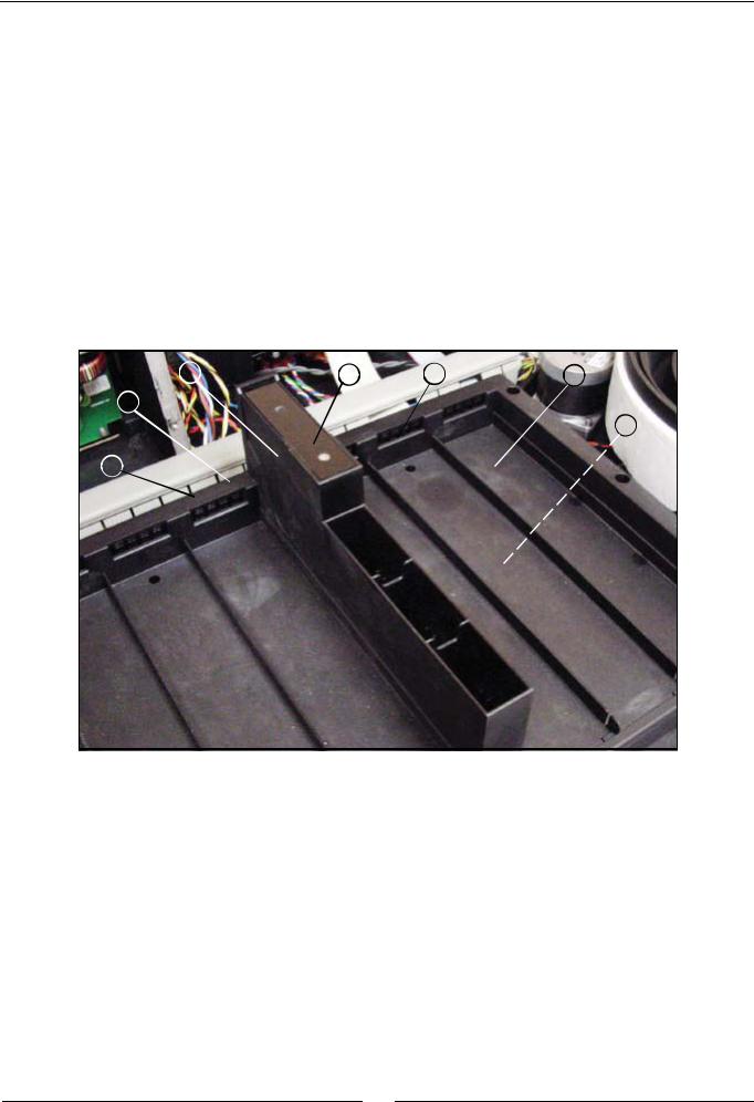
2.2.2.5. Racks tray with integrated washing station
(1)TRAY
(2)WASHING STATION
(3)WASHING STATION COVER
(4)LEVEL DETECTION SHEETING
(5)ELECTRONIC RACKS DETECTION BOARD
(6)WASHING WATER PVC TUBE
(7)WASTE EXTRACTION PVC TUBE
2 |
3 |
5 |
1 |
6
4
7
The plastic injection tray (1) is fastened directly to the base of the instrument. In the centre is the stainless steel washing station (2), covered by the lid (3). The sheeting (4) enables the detection of the level of the dispensing needle. The electronic board (5) detects the rack type placed in each of the 6 positions of the tray. The PVC tube (6) connects the washing station to the flow volume limiter of the washing pump. The PVC tube (7) connects the washing station drain to the waste extraction pump.
26
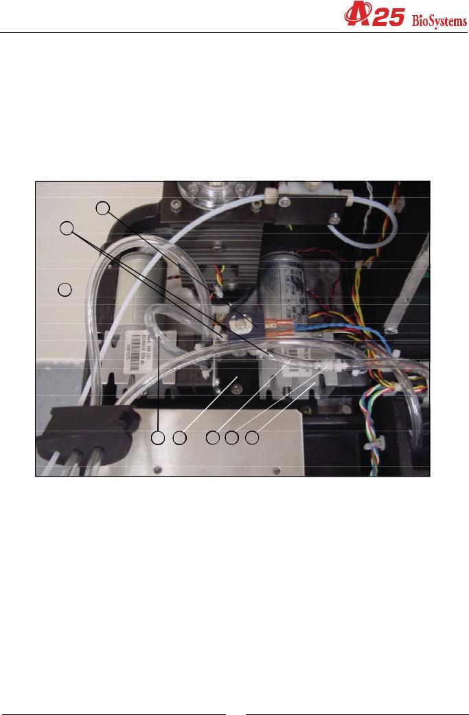
2.2.2.6. Washing pumps
(1)WASHING WATER diaphragm PUMP
(2)PUMP-ELECTROVALVE PVC TUBE
(3)2-CHANNEL ELECTROVALVE
(4)FITTINGS
(5)ELECTROVALVE-LIMITER PVC TUBE
(6)FLOW VOLUME LIMITER
(7)WASTE EXTRACTION diaphragm PUMP
(8)SUPPORT
3
4
1 
2 |
8 |
5 |
6 |
7 |
The needle washing system has two diaphragm pumps, one for the washing water (1) and another for waste extraction
(7). The PVC tube (2) connects the washing pump to the 2-way electrovalve (3), which is used to prevent the washing station from unloading and to establish the precise amount of washing water. The PVC tube (5) connects the electrovalve to the flow volume limiter (6). The electrovalve has stainless steel fittings for the connection of the PVC tubes. The support (8) fastens the pumps and the electrovalve to the base of the instrument.
2.2.3. Reactions rotor with integrated optical system
The reactions rotor is thermostated at 37ºC. The optical system, made up of a lighting system and a photometric system takes the readings directly on the rotor reaction wells. The lighting system has a halogen lamp, a filter wheel for the selection of the wavelength and various lenses to form the appropriate beam of light. The photometric system contains a silicon photodiode and the corresponding electronics to obtain a digital value that is proportionate to the light intensity received.
27
Service manual
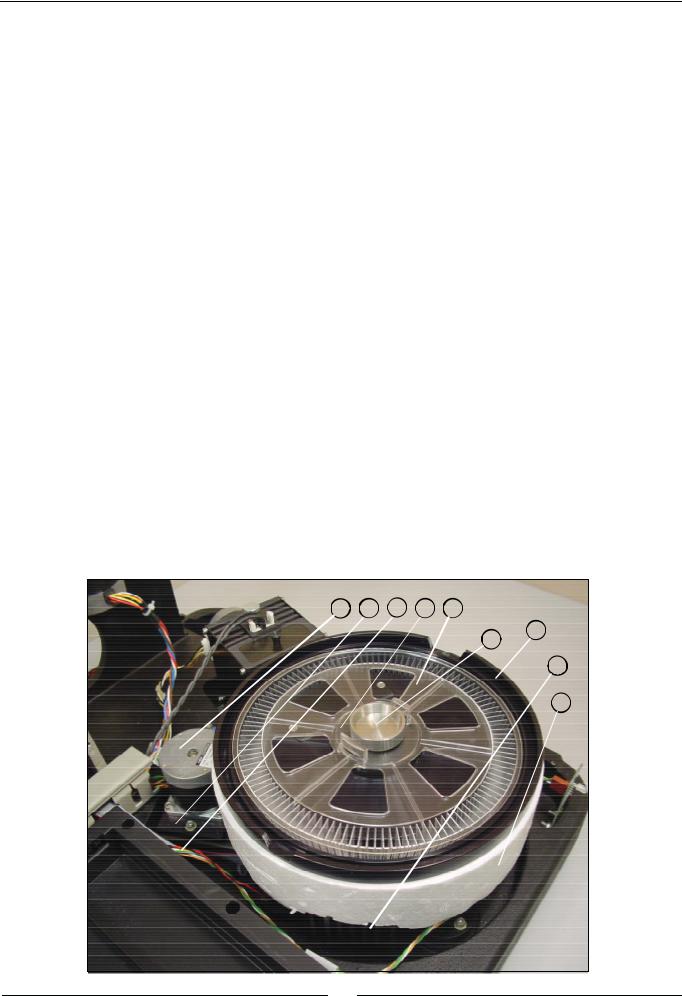
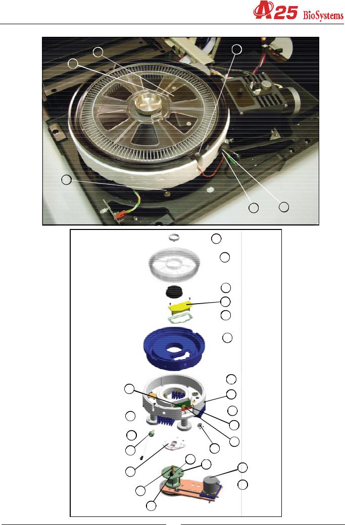
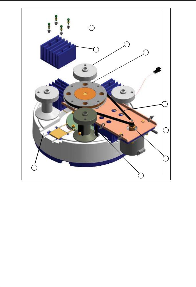
2.2.3.1. Thermostated rotor and photometric system
(1)METHACRYLATE ROTOR
(2)HEATING CHANNEL
(3)THERMAL INSULATION OF THE HEATING CHANNEL
(4)PELTIER CELLS
(5)RADIATORS
(6)THERMAL INSULATION BUSHES
(7)ROTOR FASTENING SCREW
(8)ROTOR CENTERER
(9)THERMAL INSULATION OF THE GEAR SUPPORT
(10)GEAR SUPPORT
(11)START PHOTODETECTOR
(12)ROTOR SHAFT
(13)BEARINGS
(14)ROTOR PULLEY
(15)GEARED BELT
(16)MOTOR SUPPORT
(17)MOTOR SPACER
(18)MOTOR
(19)MOTOR PULLEY
(20)PHOTOMETRIC SYSTEM SUPPORT COVER
(21)LEAKPROOF SEAL
(22)LOWER PHOTOMETRIC SYSTEM SUPPORT COVER
(23)PHOTODIODE GRILL CENTERER
(24)PHOTOMETRIC SYSTEM BOARD
(25)PHOTODIODE SPACER
(26)ROTOR GRILL
(27)TEMPERATURE PROBE
(28)THERMAL INSULATION OF PROBE
(29)COVER DETECTOR
(30)EARTH CONNECTION
(31)DRAINAGE TUBES
(32)COLUMNS
18 17 16 8 1
7
2
5
3
28
20
21
32
25
29
27
28
9
12
11
29
28 27
 7
7
 1
1
 8 20
8 20
 21
21
 2
2
 3
3
30
 24
24
22
23
26
13
10 18
 17
17
29
Service manual
 6
6
32
5
14
15
 16
16
19
4
31
The dispensing system dispenses the reagents and the samples in the methacrylate rotor (1). The optical system measures the absorbance directly on the rotor wells. The aluminium heating channel (2) surrounds the rotor and keeps it at 37ºC. The channel is thermally insulated from the exterior by means of the molded expanded polystyrene insulation
(3). The Peltier cells (4), with their respective radiators (5), act on the channel to control the temperature. The screws that fasten the radiators are thermally insulated from the former by the bushes (6). The sensor used to control the temperature is the probe (27), which is thermally insulated from the exterior of the channel by means of the sleeve (28). The methacrylate rotor is fastened to its centerer (8) by means of the screw (7). The centerer is fastened to the rotor (12), which is mounted on bearings (13) in the gear support (10). This support is screwed to the heating channel. The plastic part (9) thermally insulates both parts from each other. The barrier obstructing the photodetector (11) when the rotor reaches its start position forms part of the centerer (8). The pulley (19), fastened to the motor (18), acts, by means of the belt (14), on the pulley (14) fastened to the rotor. The gear ratio is 1:12. The spacer (17) makes it possible to move the motor on its support (16) to adjust the belt tension correctly. The electronic board of the photometric system (24) is housed in a cavity in the heating channel. The upper cover of this cavity (20) supports the electronic board. The seal (21) keeps the cavity hermetically closed in the case of possible liquid spillage. The cavity is closed at the bottom by the cover (22). The photodiode is welded onto the board on the spacer (25). The part (23) centers the photodiode with regard to the lighting system and also acts as a grill to prevent the incidence of unwanted light. The grill (26) limits the light hitting the reactions rotor. The detector (29) tells the analyzer if the rotor cover is in position or not. The part (30) connects the heating
30
 Loading...