


SERVICE MANUAL
MS330IA031203

II

INDEX
1. INTRODUCTION 1-1
2. FUNCTIONAL PARTS DESCRIPTION 2-1
2.1. Optical system 2-1
2.1.1. Constitutive parts 2-1
2.1.2. System description 2-1
2.1.3. Physical description 2-2
2.1.4. Signal conditioning 2-2
2.1.5. Adjustment 2-7
2.1.6. Precautions and maintenance 2-7
2.2. Aspiration system 2-7
2.2.1. Components 2-7
2.2.2. System description 2-7
2.2.3. Physical description 2-8
2.2.4. Programmable parameters 2-8
2.2.5. Programming 2-8
2.2.6. Adjustment 2-8
2.2.7. Precautions and maintenance 2-9
2.3. Thermostatization system 2-9
2.3.1. Components 2-9
2.3.2. System description 2-9
2.3.3. Physical description 2-14
2.3.4. Programming 2-14
2.3.5. Adjustment 2-14
2.3.6. Precautions and maintenance 2-14
2.4. Communications system 2-15
2.4.1. Channel type 2-15
2.4.2. Channel characteristics 2-15
2.4.3. Information transmitted 2-15
2.4.4. Programming 2-16
2.5. Block diagram 2-18
2.5.1. Logarithmic amplifier 2-18
2.5.2. Analogic/Digital converter 2-18
2.5.3. Lamp control 2-18
2.5.4. Filters wheel detector 2-18
2.5.5. Filters wheel motor control 2-18
2.5.6. Temperature sensor amplifier 2-18
2.5.7. Peltier cell control 2-18
2.5.8. Pump motor control 2-19
2.5.9. Keyboard circuit 2-19
2.5.10. Printer control 2-19
2.5.11. Display circuit 2-19
2.5.12. RS-232 channel circuit 2-19
2.5.13. Fan control 2-19
2.5.14. Microcontroller 2-19
I

2.5.15. Power supply 2-20
2.5.16. Reset and battery-backup supervisory circuit 2-20
2.6. Electronic circuit description 2-20
2.6.1. Logarithmic amplifier 2-20
2.6.2. Analog to digital converter 2-22
2.6.3. Lamp control 2-22
2.6.4. Filter wheel detector 2-22
2.6.5. Filters wheel motor control 2-23
2.6.6. Temperature sensor amplifier 2-23
2.6.7. Peltier Cell control 2-23
2.6.8. Pump motor control 2-24
2.6.9. Keyboard circuit 2-24
2.6.10. Printer control 2-25
2.6.11. Display circuit 2-25
2.6.12. RS-232 channel circuit 2-26
2.6.13. Fan control 2-26
2.6.14. Microcontroller 2-26
2.6.15. Power supply 2-27
2.6.16. Microcontroll e r supervisory and reset circuit 2-27
3. CHECKS AND ADJUSTMENTS 3-1
3.1. Service menu 3-1
3.1.1. Option TEST 3-1
3.1.2. Option ADJUSTMENTS 3-2
3.1.3. Option UNLOCK/LOCK TESTS 3-2
3.1.4. Option UNLOCK/LOCK instrument 3-2
3.2. ADJUSTMENTS 3-2
3.2.1. Photometric adjustment 3-2
3.2.1.1. Materials needed 3-3
3.2.1.2. General remarks 3-3
3.2.1.3. Procedure 3-3
3.2.2. Thermostatic system adjustement 3-4
3.2.2.1. Materials needed 3-4
3.2.2.2. General remarks 3-4
3.2.2.3. Procedure 3-4
3.2.2.4. Explanation of the list parameters 3-5
3.2.2.4. Check 3-5
3.2.3. Filters wheel adjustment 3-5
3.2.3.1. Materials needed 3-6
3.2.3.2. General remarks 3-6
3.2.3.3. Manual mode 3-6
3.2.3.4. Automatic mode 3-7
3.2.4. Peristaltic pump adjustment 3-8
3.2.4.1. Materials needed 3-9
3.2.4.2. General remarks 3-9
3.2.4.3. Check method 3-9
3.2.4.4. Manual mode 3-9
II

3.2.4.5. Automatic mode 3-10
3.3. Transformer and power supply checking 3-11
3.4. Fan checking 3-12
3.5. Optical system checking 3-12
3.6. Check of the sensitivity with flow cuvette 3-13
4. CHECK TESTS 4-1
4.1. Activation of a test 4-1
4.2. Screen 4-1
4.3. Buzzer 4-1
4.4. Keyboard 4-1
4.5. Printer 4-1
4.6. Serial Port RS-232 4-1
4.7. Motors 4-2
4.7.1. Loss of steps of the peristaltic pump 4-2
4.7.2. Loss of steps of the filters wheel 4-2
4.8. Cuvette temperature 4-2
4.9. Carry Over 4-3
4.10. Photometry 4-3
4.10.1. Filter sensitivity 4-3
4.10.2. Electric noise 4-3
4.10.3. Stability of the readings 4-4
4.10.4. Precision 4-4
4.10.5. Accuracy 4-5
4.11. Unlock / Lock QC techniques 4-5
5. MAINTENANCE 5-1
5.1. Case replacement 5-1
5.2. Main board replacement 5-3
5.3. Change of the display board 5-3
5.4. Printer replacement 5-7
5.5. Keyboard replacement 5-7
5.6. Transformer replacement 5-9
5.7. Cuvette holder tray removal 5-9
5.8. Filters wheel replacement 5-10
5.9. Filters wheel motor replacement 5-10
5.10. Peristaltic pump replacement 5-11
5.11. Peltier cell replacement 5-11
5.12. Change of the photodiode 5-12
5.13. Fan replacement 5-14
5.14. Temperature sensor replacement 5-14
5.15. Lamp replacement 5-15
5.16. Filters replacement 5-17
5.17. Lenses replacement 5-17
5.18. General care 5-18
III

5.19. Cleaning of the optical components 5-20
5.20. Cleaning the filters 5-23
5.21. Cleaning the lenses 5-23
5.22. Cleaning the photodiode 5-23
5.23. Cleaning the aspiration system 5-23
5.24. Cleaning the flow-cuvette 5-24
5.25. General cleaning of the instrument 5-24
APPENDIX I. TECHNICAL SPECIFICATIONS I-1
I.1. Optical system I-1
I.2. Thermostatic control I-1
I.3. Printer I-1
I.4. Display I-1
I.5. Electronics I-2
I.6. Communications I-2
I.7. Installation I-2
I.8. Dimensions and weight I-2
I.9. Cuvette systems I-2
I.10. Flow system I-3
I.11.- Environmental conditions I-3
APPENDIX II. CALIBRATION TOLERANCES TABLES II-1
II.1. Photometric adjustment Tolerances II-1
II.2. Filters Wheel Adjustment II-1
II.3. AC Voltage of the Transformer Secondaries II-1
II.4. Filters sensitivity without flow cuvette II-2
II.5. Electric Noise II-2
II.6. Filters sensitivity with flow cuvette II-2
II.7. Fan Voltage Control II-3
II.8. Zero-Currents for the Sensitivity Test II-3
II.9. Heating Adjustment II-3
II.10. Peristaltic Pump Adjustment II-3
APPENDIX III. DEFAULT PARAMETERS III-1
APPENDIX IV. MAINTENANCE PLAN IV-1
IV.1. Cleaning
IV-1
IV.2.Change IV-1
IV.3. Review IV-1
IV.4.Check IV-1
IV
APPENDIX V. SPARE PARTS AND ACCESSORIES V-1
V.1.Accessories V-1
V.2.Authorized Spare Parts V-2
APPENDIX VI. PASSWORD VI-1
APENDIX VII. SOFTWARE VERSIONS VII-1
APENDIX VIII. COMPATIBILITY TABLE TO UPDATE SOFTWARE VIII-1
VERSIONS
ESQUEMAS
Shematic distribution E33000A
Monocard (1-4) E33001A
Monocard (2-4) E33001A
Monocard (3-4) E33001A
Monocard (4-4) E33001A
Display / Printer (1-2) E33003A
Display / Printer (2-2) E33003A
Keyboard-330 E33005A
Photodetector E33009A
MODIFICATIONS
1 Modification
- This is to make compatible in U7 the integrated circuits MAX691
(Maxim) or ADM691 (Analog Devices). 1-1
- Schemes 1-2
2 Modification
- This is to all devices to be only one monocard 2-1
- Schemes 2-2
3 Modification
- The problem is the transform of inverter circuit fails 3-1
- Photos 3-2
- Schemes 3-5
V

4 Modification
- Modification for recode the components to improve their description 4-1
5 Modification
- Modification for change the display circuit board version 5-1
-Schemes 5-2
VI

1. INTRODUCTION
This instrument instrument, due to its compact design and the reduced number
of components, is a simple, easy-to-maintain one. The computer design has
allowed to study the tolerance of all the optical block’s components, making
unnecessary any mechanical adjustment. Most of its parts are aluminum or
plastic-injected and so a maximum simplicity with reduced maintenance
requirements has been achieved.
Electronic adjustments are also avoided because of the modern, highintegrated circuits used. A powerful software allows the adjustment of most of
the parameters used. Corrections are made via software, using reference tool s
or calibrators.
All the electronic parts are located in two printed circuit boards (PCB’s), and
the software has a lot of check programs to make easy the search and
diagnosis of fail u res.
This manual is not only a guide for maintenance but a document for Technical
Assistance Service staff’s training. The running principles as well as the
electronic circuits are explained in order to get a global vi ew of the instrument.
Note: Throughout this manual, the Absorbance Unit is abbreviated as "Abs"
instead of "A", in order to avoid confusion with the electric current unit, the
Ampere, represented as "A".
1-1

1-2

2. FUNCTIONAL PARTS DESCRIPTION
This instrument is composed of the following functional parts:
a) An optical system to carry out the readings.
b) An aspiration system based on a peristaltic pump, to introduce the sample
in the flow cuvette.
c) A thermostatic system to carry out reactions into the cuvettes at a constant
temperature, when needed.
d) A communications interface, allowing the connection to a host computer by
means of a proper software.
e) A microcontroller-based system, wich controls most of funtional parts.
The next sections describe each one of the functional parts.
2.1. Optical system
2.1.1. Constitutive parts
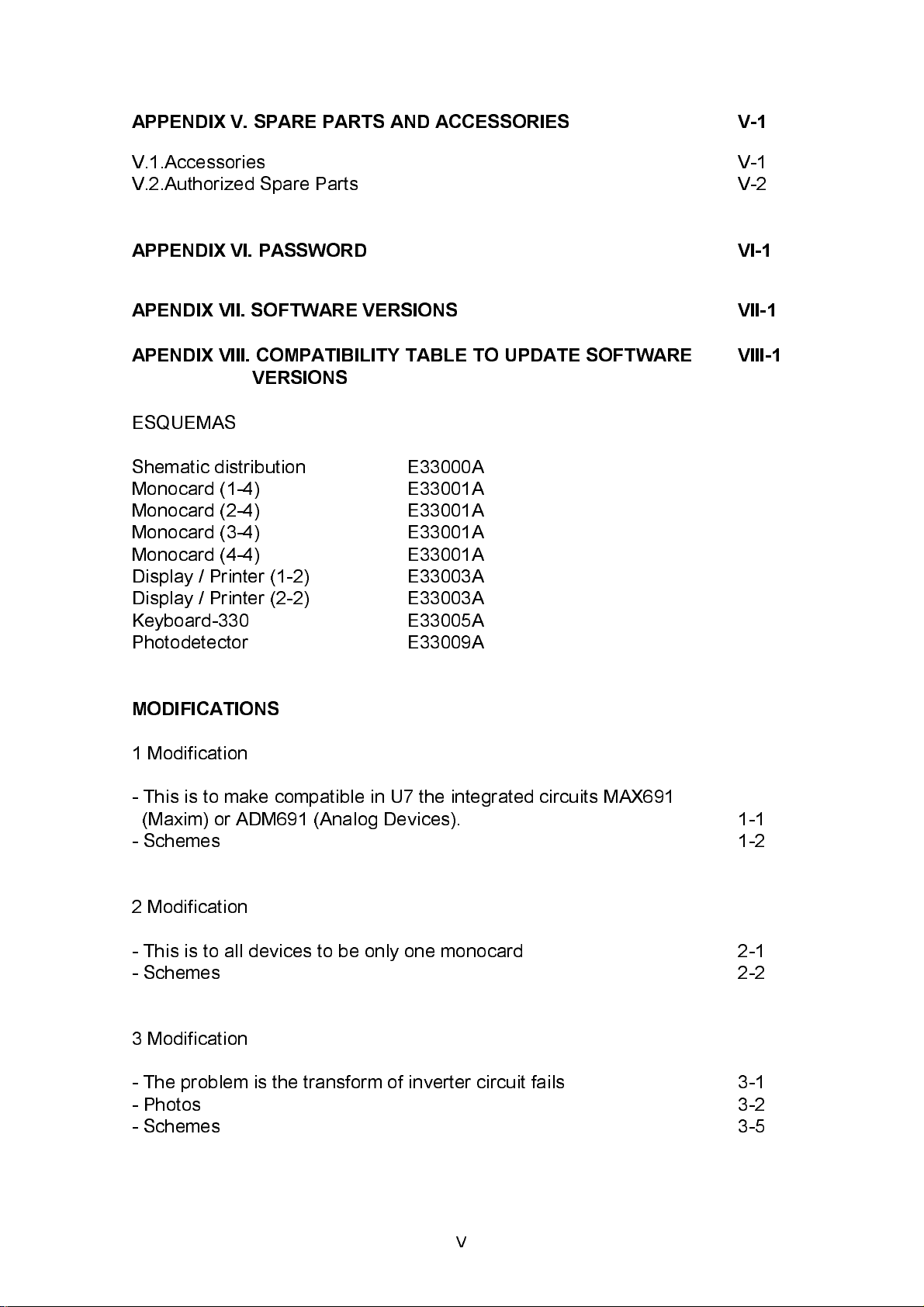
Figure 2.1. shows the optical system. It consists in:
a) An halogen lamp (1)
b) A diaphragm (2)
c) A first plano-convex lens (3)
d) An interference filter (4)
e) A second plano-convex lens (5)
f) A cuvette (6)
g) A silicon photodiode (7)
2.1.2. System description
The first component is the light source: one halogen lamp (1). The di aphragm
(2) delimits a light solid angl e that is collected by the first lens (3). It sends a
parallel beam to an interference filter (4). Thi s is one of the nine possibl e ones
located in the wheel. One stepper motor drives this wheel and, controlled by
the program, place the proper filter in the opti cal axis, in front of the l i ght beam.
Each filter monochromes one wavelength with the characteristics described in
section I.1.
A second lens (5) focuses the monochromatic beam in the cuvette center (6). In
case of flow cuvettes, the light path hole itself behaves as a diaphragm,
decreasing the sensitivity, that it is lower than in the common cuvettes. The
2-1

light beam goes through the cuvette as far as a light sensor (7), that converts
the light beam into electric current.
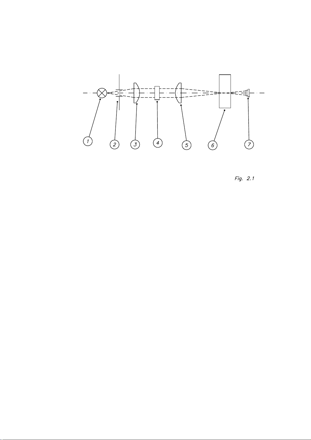
2.1.3. Physical description
The optical system (figure 2.2) consists in an injected-aluminum holder (1)
where there are mounted the following components:
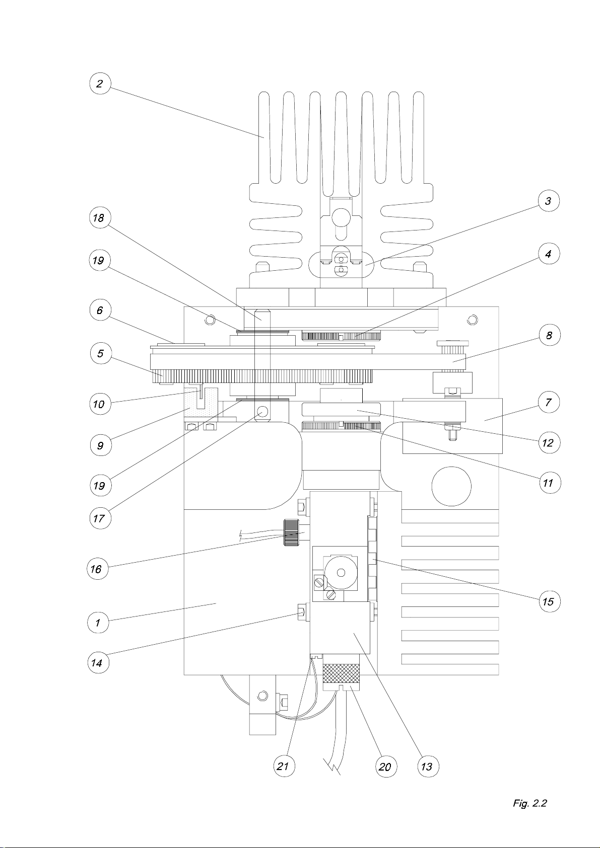
- A heat sink shape aluminium block (2) containing a lamp-holder (3). That
block includes a diaphragm (figure 2.3 (1)) that delimits the a light solid angle.
- A lens holder (4) that contains the first lens.
- A filters wheel (5), with capacity for 9 filters. This fil ters must be mounted in
special holders (6). Thi s wheel is moved through a belt (8) by a stepper motor
(7). A photointerrupter (9) allows the detection of a stem (10) that indicates the
filters wheel home position.
- A lens holder (11) that contains the second lens.
- A light protector (12), fitted together the second lens holder, avoids the
parasite light in terference.
- A cuvette-holder (13) holds both the cuvette and the photodiode detector. The
thermostatic system is fitted together (see section 2.3.).
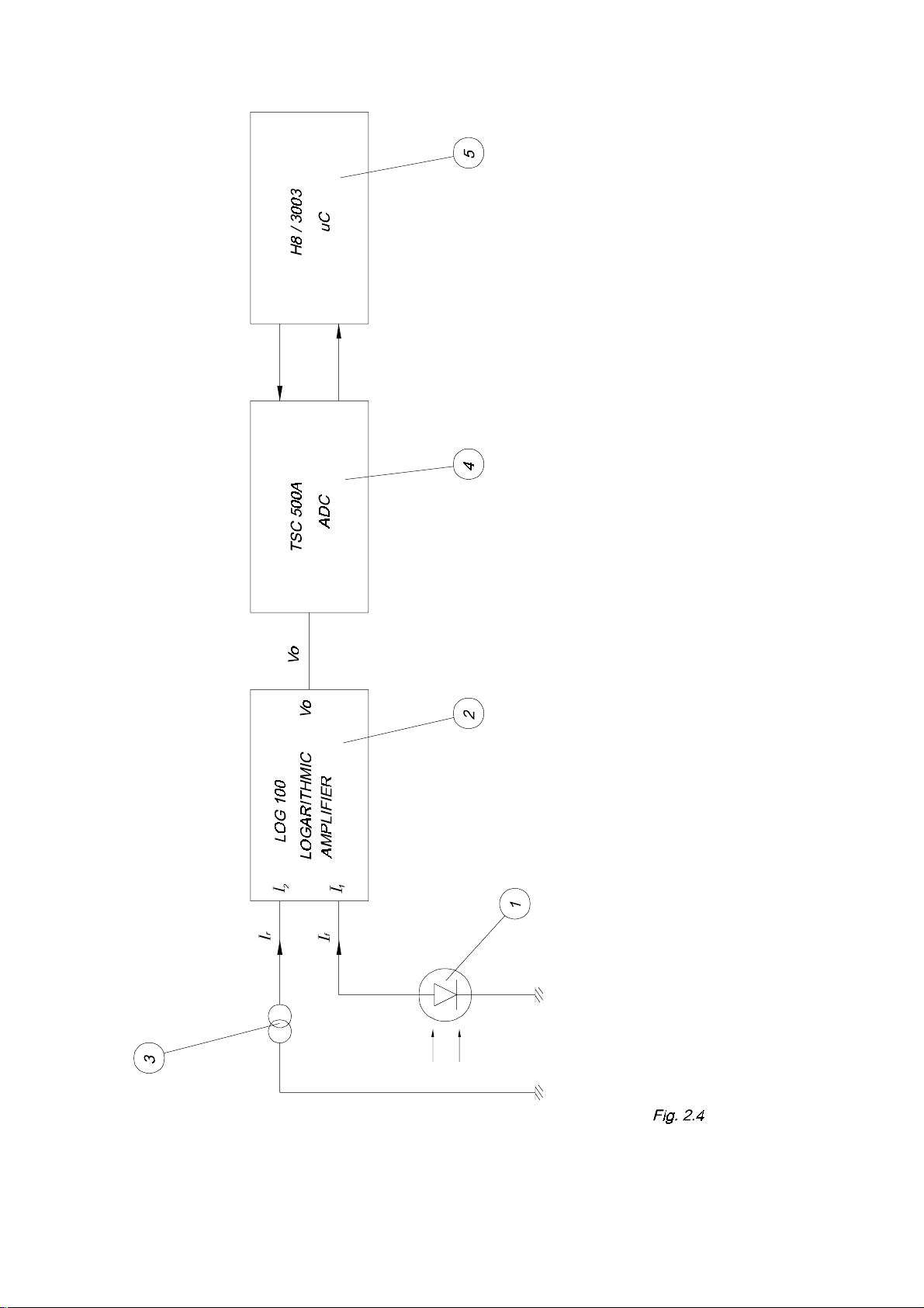
2.1.4. Signal conditioning
(See figure 2.4) The photodiode (1) gives an electric current (If) directly
proportional to the received light. Thi s current goes to the input I
100 logarithmic amplifier (2). A reference current I
introduced by input I
I
. The output voltage of LOG-100 is:
2
f
(3) (nominal 100 nA) is
r
of the LOG-
1
V0 = k x log ---------- I
r
In this case, k=1 and V0 = 1 volt/Abs.
2-2
2-3
2-4
2-5
2-6

V
is digitali zed by the double-ramp converter TSC500A (4) with a resolution of
0
10,000 counts per volt. The conversion time depends on the absorbance value
and increases together with it; for instance, 2 Abs time is 0.15 sec. This
converter is controlled by the microcontroller (5).
2.1.5. Adjustment
The global system (optical system, amplifier and converter) is not stri ctly l inear
due to the components tolerance, so that it is necessary to do some
adjustments to compensate the inherent deviations of the system.
The photometric adjustment is performed in ranges; between 0 and 2 Abs.
Several value ranges are determined and different correction factors are
applied depending on the range. As deviation also depends on the wavelength,
it is necessary to adjust with different filters. Adjustment process is described in
section 3.2.
2.1.6. Precautions and maintenance
Maintenance of the optical system should be carried out according to the
instructions given in section 5.20.
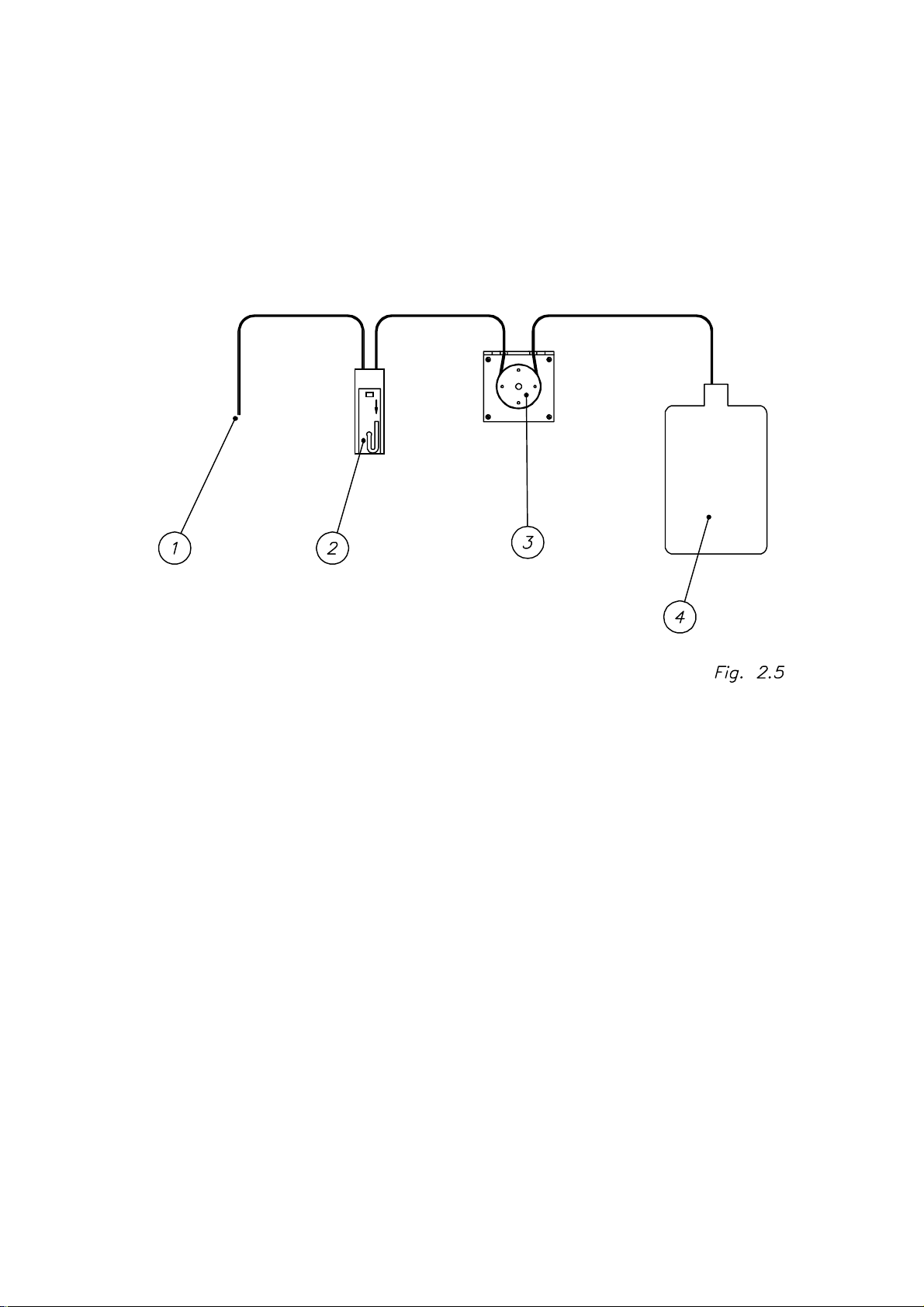
2.2. Aspiration system
2.2.1. Components
The aspiration system is composed of the following parts (figure 2.5):
a) Sipping tubing (1)
b) Flow cuvette (2)
c) Peristaltic pump (3)
d) Waste bottle (4)
2.2.2. System description
The sample is sipped by the sipping tubing (1). This tubing, Teflon made, has a
standard length and the system is adjusted in accordance with it. The sipped
sample enters into the flow cuvette (2), where readings take place. Sipping is
performed through a silicone tube by means of a peristaltic pump (3), made up
of a four-rollered rotor that is contolled by a stepper motor. Finally, the sample
ends into the waste bottle (4).
2-7

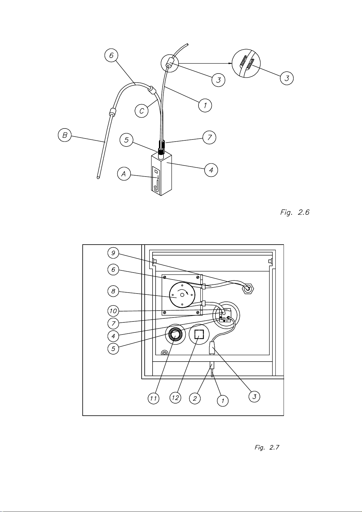
2.2.3. Physical description
The sipping tubing (figures 2.6 and 2.7) is placed on the cuvette-holder tray.
The silicone tube (1), that crosses the case through a steel guiding tube (2), is
fixed to this guiding tube by means of a silicone connector (3) and to the
cuvette (4) by means of an inlet adapter (5). The teflon tube (6) is connected to
the cuvette by an outlet adapter (7), placed in the peristaltic pump (8) and
finally connected to the waste outlet (9).
The waste bottle (1) (figure 2.8) is connected to the outlet (2) in the back of the
instrument by means of a silicone tube (3).
2.2.4. Programmable parameters
Three parameters control the sipper functioning and they must be programmed
to obtain the expected performance characteristics. Their programming is
explained in the user’s manual.
a) SAMPLE VOLUME. It is a number that indicates the volume of sample to be
sipped, in
P
l.
b) PUMP DELAY. It is the number of seconds the pump will wait since the
sipping finishes till the pump is activated again to position the sample into the
flow cuvette.
c) POSITIONING. It is the number of steps that the peristaltic pump’s motor
gives to set the sample into the flow cuvette, ensuring that it is suitably
positioned in order to be read.
2.2.5. Programming
The aspiration system’s programming must be performed in order to indicate
the instrument the volume, in microlitres, to be sipped.
2.2.6. Adjustment
The pump’s nominal flow is 110 PL/revolution, nevertheless, the accuracy of
this figure depends on the tolerances in length and diameter of the sipping
tube, that may be affected by the aging of the tube itself; this is why this value
should be adjusted from time to time. The adjustment process is explained in
section 3.5. As it can be also done by the user, it i s also explai ned in the user's
manual.
2-8

2.2.7. Precautions and maintenance
The general rules for the aspiration system’s maintenance are the same as the
ones given in section 5.24.
Weekly adjustment of the aspiration system is strongly recommended.
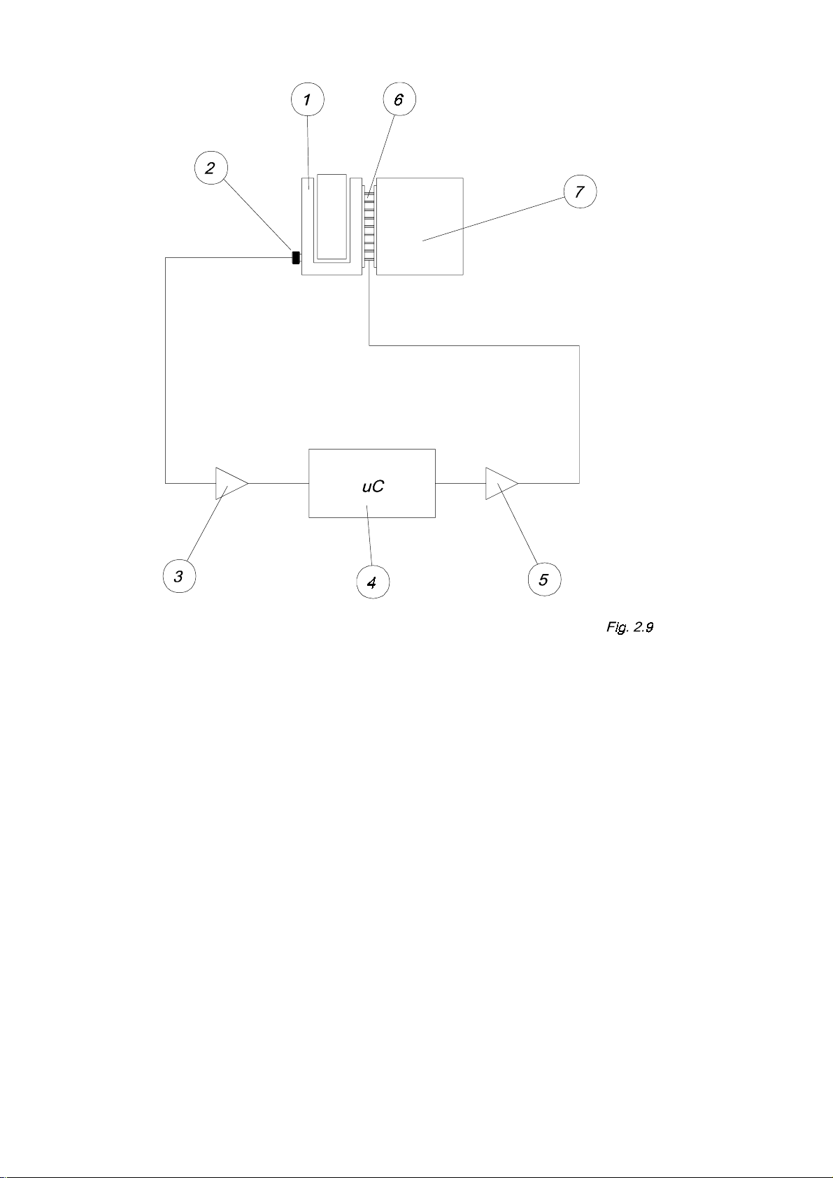
2.3. Thermostatization system
2.3.1. Components
Figure 2.9 shows an schema of the thermostatization system, that is composed
by the following parts:
a) A cuvette-holder (1)
b) A temperature sensor (2)
c) An amplifier of the temperature sensor (3)
d) The microcontrollers’ A/D converter (4).
e) A Peltier Cell’s in-circuit power driver(5).
f) A Peltier Cell (6)
g) A heat sink block (optical system holder) (7).
2.3.2. System description
The cuvette with the reaction mixture to be thermostatized is placed in its
holder (1). Thermal contact is settled between the cuvette and the holder.
The cuvette-holder is isolated from the optical system holder (7) and contacts
one of the Peltier Cell’s faces (6). The other cell ’s face is in contact with the
optical system holder.
The Peltier Cell pumps heat from one face to the other, depending on the
current sense. The power control circuit (5) is in charge of making that current
circulate in the adequate sense inside the Cell, in order to heat or cool
depending on the microcontroller’s instructions.
When heating, heat is pumped from the environment (taken from the optical
system holder) to the cuvette-holder and when cooling the opposite is done.
The optical system holder has a heat sink block to cool the heat coming from
the cuvette-holder. A temperature sensor (2) gives a small voltage, directly
proportional to the cuvette-holder’s temperature, that is conditioned by one
amplifier (3) and read by the microcontroller’s A/D converter (4). The
microcontroller’s thermostatization program, depending on the programmed
temperature and the read value, activates the power control (5) heating or
cooling as required.
2-9
2-10
2-11

Fig 2.8
2-12
2-13

2.3.3. Physical description
The cuvette-holder (13) (figure 2.2) is fixed to the optical system holder (1) by
means of four screws (14) thermally isolated. The Peltier Cell (15) is located
between the cuvette-holder (13) and the optical system holder (1). The
temperature sensor, located in a plastic holder (16) is fixed to the cuvetteholder by a thread.
2.3.4. Programming
Programming the thermostatization system consists in indicating the i nstrument
which temperature is desired for the reaction mixture. This value may
introduced in several program’s points.
2.3.5. Adjustment
Components’ tolerance produce a deviation between the programmed
temperature and the real one, so it is necessary an adjustment procedure to
compensate such deviations. The thermostatization adjustment procedure is
described in section 3.3.
2.3.6. Precautions and maintenance
The thermostatization system has two critical poi nts: the good thermal contact
between both faces of the Peltier Cell with the optical system holder and the
cuvette-holder, and the good thermal contact between the temperature sensor
and the cuvette-holder.
To ensure proper conditions in both points, the following cautions should be
taken into account:
a) A thin, uniform layer of silicone must be placed in each face of the Peltier
Cell, covering the whole surface.
b) The silicone layer should neither go beyond the surface of the Cell, nor go
inside between its two faces; it would result in a thermal short-crossing that
would reduce the system’s performance.
c) The temperature sensor should have a silicone layer in order to make a
good thermal contact with the bottom of its lodging.
For assembling these components, follow the procedures described in secti ons
5.11. (changing the Peltier Cell) and 5.14. (changing the temperature sensor).
2-14

2.4. Communications system
This instrument is equipped with a communication channel all owing connection
with computers. The operation of this communication channel depends on the
program release and the computer’s applicati on software.
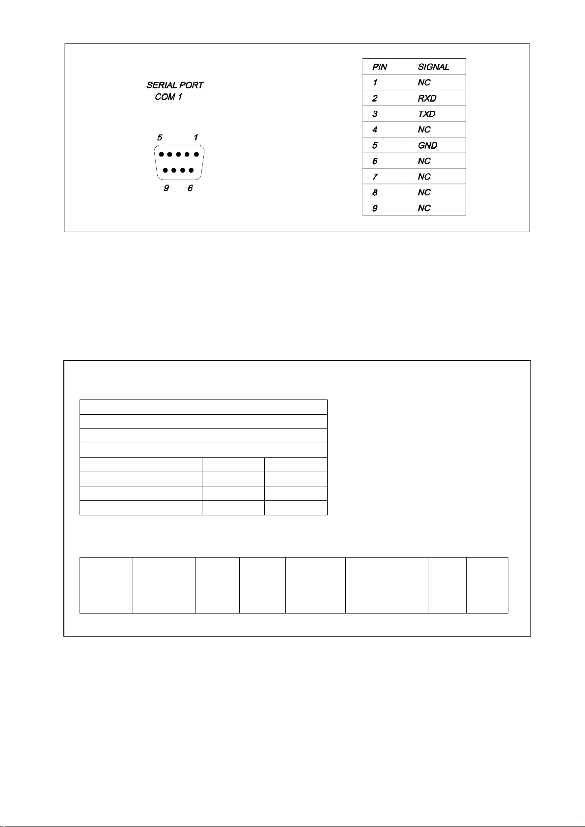
2.4.1. Channel type
The communication channel is a RS-232, and uses the following connection
lines:
RxD: Receiver Data
TxD: Transmitter Data
GND: Ground (0 volts)
The connector is located in the instrument’s back side, rounded by a box
labeled COM 1. The signals’ electric level meets the E.I.A. RS-232 standard.
Figure 2.10 describes the connector’s signals.
2.4.2. Channel characteristics
The serial channel is pre-programmed by the manufacturer with next default
parameters:
Baud rate: 9600
Timeout:: 0
Terminal number: 0
2.4.3. Information transmitted
The communications procedure uses a ‘sending & waiting’ protocol . Every time
the transmitter sends a message, it waits for an ‘ok’ from the receiver. If the ‘ok’
message is not received, after a programmable timeout period the message is
sended again. The CRC-16 error-detection code is used to check the received
messages.
The communications procedure works using a
MASTER-SLAV
E method, so it
is possible to communicate several instruments at one time. To achieve this,
every instrument has to be configured with a different identification terminal
number. This parameter is configured in the CONFIGURATION /
COMMUNICATIONS menu.
Communications are always started by the
SLAVE
when it is required by the
(the instrument) is in a ‘hearing’ mode, and only sends information
MASTER
.
2-15
MASTER
(the computer). The

The instrument can send the information below:
- Quality control val ues
- Concentration values
In order to get the communication between the computer and the i nstrument, a
proper computer-running software is needed. This program save the data
received from the instrument into the computer hard disk. These data are
stored in an
EXCEL
compatible format.
The file format used is showed in figure 2.11.
2.4.4. Programming
In order to get a suitable communication with a computer through the serial
channel, it is necessary to fit the configuration parameters with the computer
ones. If the computer parameters are not known, refer to its manual. Usually
they are likewise programmable, in most cases from the application programs
themselves.
The instrument can be programmed with the next parameters: transmission
speed (bauds), timeout and terminal number. In the user’s manual is explained
how to program these parameters.
2-16
- Quality control values:
Test’s name
Control 1 or Control 2
Control’s name
Control’s lot
Concentration Date Alarm
Concentration 1 Date 1 Alarm 1
Concentration 2 Date 2 Alarm 2
Concentration n Date n Alarm n
Concentration values:
Test’s
name
Sample’s
number or
patient’s
code
Blank Factor Control-1,
Control-2
or sample
id.
2-17
Concentration Units Date
Fig.2.11

2.5. Block diagram
The block diagram (figure 2.12) is intended to give a general overview of the
the electronic circuit’s different parts.
2.5.1. Logarithmic amplifier
It converts the electric current coming from the photodiode in a voltage equal to
its logarithm (section 2.1.4.).
2.5.2. Analog to digital converter
It digitalizes the voltage coming from the logarithmic amplifier for its further
treatment by the microcontroller.
2.5.3. Lamp control
It supplies the regulated 12V that the lamp needs to work properly.
2.5.4. Filters wheel detector
It is a photointerrupter to detect the filters wheel home position. Allows the
microcontroller to know the location of each filter thus being able to position
them in front of the light beam.
2.5.5. Filters wheel motor control
This is a circuit that, by means of the microcontroller’s logic control, supplies
power to the stepper motor that moves the filters wheel.
2.5.6. Temperature sensor amplifier
This is a circuit to make the signal conditioning for the temperature sensor’s
voltage level in order to be measured by the microcontroll er’s 10-bits analog to
digital converter, with a resolution enough to adjust the system.
2.5.7. Peltier cell control
This is a microcontroller-controlled power circuit that supplies the Peltier cell
the adequate current to heat or cool the cell-holder.
2-18

2.5.8. Pump motor control
This is a circuit that, by means of the microcontroller’s logic control, supplies
the needed power to the stepper motor that moves the peristaltic pump.
2.5.9. Keyboard circuit
This circuit basi cally consists in the keyboard itself and some protection diodes.
2.5.10. Printer control
It consists in the power circuits that allow the orders coming from the
microcontroller to act on the printer, either moving the motors or heating the
thermal head points.
2.5.11. Display circuit
This circuit consists in the display itself, the control and supply lines, one
inverter circuit for the CFL backlight and one circuit to control the LCD contrast
adjustment.
2.5.12. RS-232 channel circuit
It is formed by the circuits needed to make the signal conditioning from TTL
voltage level to the RS-232 standard. The ACIA is integrated in the
microcontroller itself.
2.5.13. Fan control
This is a circuit that measures the temperature in the power supply’s heat sink
and changes the fan’s speed according to the cooling necessi ty. A more silent
working conditions are thus achieved.
2.5.14. Microcontroller
By means of its program, it is in charge of li nking and control ling almost all the
instrument systems. Only the fan’s circuit and the lamp’s one are not controlled
by the microcontroller.
2-19

2.5.15. Power supply
It is in charge of supplying the needed voltages to the different instrument
parts.
2.5.16. Reset and battery-backup supervisory circuit
When the instrument is turned on, this circuit is in charge of keeping the
microcontroller and other chips (like memories) in a ‘reset state’ until the suppl y
voltage reaches the proper working level, avoidi ng undesired effects when the
instrument is powered on, as well as protecting the RAM against erroneous
writings during the on / off voltage transitions.
Also, this circuit provi des a batery backup switchover every ti me the i nstrument
is switched ON/OFF
2.6. Electronic circuit description
This section describes the different electronic parts, following the functional
structure given in section 2.5.
2.6.1. Logarithmic amplifier
(See schema E33001A, sheet 1)
The logarithmic amplifier is formed by the hybrid circuit LOG-100 (U16). Its
supply voltage is
r
15 V. C90, C91, C96 and C97 are bypass capacitors that
store electrical charge that is released to the power line whenever a transient
voltage spike occurs. The photodiode is connected between ground and the
input I1 (1/U16). A reference current (section 2.1.4.) is generated i n the 2.5 V
voltage regulator TL431CD (U15) and the T-circuit formed by R45, R51 and
R52. Its nominal value is 100 nA. The LOG-100 has the output OUT (7/U16)
connected to the pin K1 (3/U16), thus being the logarithmic conversion
constant (K) equal to 1. The capacitor C92 is for circuit stability.
2-20

2-21

2.6.2. Analog to digital converter
(See schema E33001A, sheet n. 1)
The logarithmic amplifier’s output voltage (7/U16) is applied to the A/D
converter’s input VIN(+) (11/U19) through a RC net formed by R56 and C93.
This converter takes as a reference the U15 2.5 V voltage and is supplied at r5
V. The voltages are reached from r15 V by means of the D16 and D17 zeners
and bypassed using the capacitors C80, C81, C83 and C84. The capacitors
C99, C100, C101 and the resistor R60 belong to the converter circuit. This
capacitors must be of polypropylene type in order to have very low leakage
currents.
As the voltage in 7/U16 can vary in the r15 V range while the input voltage of
11/U19 cannot exceed the U19 supply voltage (5 V), the circui t formed by D8,
D9, D10, D12, R43 and R44 protect it against overvoltages.
2.6.3. Lamp control
(See schema E33001A, sheet n. 2)
The lamp’s power supply is done through the circuit formed by the RG1
regulator. It receives the non-regulated voltage from the 0-15 Vac transformer’s
coiling. Thi s voltage is rectified by the bridge D2 and fil tered by C14 and C15
(C17 is the bypass capacitor). The 12V output voltage is given by the resi stors
R19 and R20.
2.6.4. Filter wheel detector
(See schemes E33009A and E33001A, sheet n. 1)
The wheel detector consists in the photointerrupter MCT-81 according to the
schema E33009A and it is mounted on the printed circuit reference 1363. The
schema E33001A shows the resistor R46 connected to the emitter photodiode’s
anode, as a power supply, and the resistor R41 connected to the collector, as a
load. From this point the logic signal is taken and read by the microcontroller
pin PC4 (15/U13).
Under normal conditions, the photodiode’s infra-red light reaches the
phototransistor, which starts to work in saturation mode and the signal in its
collector is a logic "0". When the filters wheel turns and the detection stem
interrupts the light from the photodiode, the transistor stops conducing and the
signal in its collector is a logic "1".
2-22

2.6.5. Filters wheel motor control
(See schema E33001A, sheet n. 2)
The filters wheel stepper motor control is achieved by two integrated circuits
PBL3717A (U5 and U6). These circuits are constant current stepper motor
drivers. Each one supplies the current to one of the motor coils. This current
depends of the reference voltage applied in the REF pins (11/U5 and 11/U6).
This voltage is generated by the 12 V zener D3, the resistors R23 (i n U5) and
R24 (in U6) and the internal voltage dividers of these ci rcuits. C13 and C36 are
bypass capacitors for the +5 V supply voltage of these circuits. The other
connected components complete its operation.
2.6.6. Temperature sensor amplifier
(See schema E33001A, sheet n. 1)
The temperature sensor generates a voltage proportional to the temperature
expressed in Kelvin degrees (Celsius + 273), equal to 0.01 V/
q
K. So, for
instance,
at 25qC VT = (25+273) x 0.01 = 2.98 V
at 37qC VT = (37+273) x 0.01 = 3.10 V
The U20 amplifier and its associated circui t make these voltages adequate to
be read with the maximum resolution by the 10-bit A/D converter of the Hitachi
H8/3003 microcontroller. The adequate voltage exits by 6/U20 and it is applied
to the microcontroller’s input AN0 (86/U13) through the resistor R47.
As the voltage coming from 6/U20 can vary in the range r15 V and the input
voltage of 86/U13 cannot exceed the converter reference voltage applied to
AVCC (84/U13) (5 V), the circuit formed by D11, D13, D14, D15 and R50 is in
charge of keeping this input between this value and ground.
2.6.7. Peltier Cell control
(See schema E33001A, sheets n. 1 and 2)
A low-voltage, full-wave rectified voltage is applied to the Peltier Cell, in the
sense adequate for heating or cooling. Although the use of this current l owers
the performance of the cell, its use is justified by the simplicity of the circuit.
The full-wave rectification in both senses is achieved using two triacs and a
center-tapped coiling. Each triac can l et a positive or negative hal f-wave pass,
when convenient. The circuit formed by the amplifier TL072CD (U3A), that
works as a comparator, and the transistor BC548 (T5), that makes the output
2-23

1/U3A (r15 V) adequate to logic level (0 at +5 V), form a polarity detector for
the alternating voltage that suppl ies the power control circuit.
This signal is appli ed to the microcontroller by the pin P71 (87/U13) in order to
know which triac and when should be activated. The microcontroll er activates
the triacs by means of two signals leaving by pins PA6 (111/U13) and PA7
(112/U13) and that, together with the polarity detection signal (col l ector T5) are
applied to the programmable logic circuit XC9572-PC84 (U9) to generate the
two triacs‘ control signals (77/U9 and 6/U9) and avoid a simultaneous
activation caused by a program error. Circuits 2/U1A, 4/U1B and the transistors
T1 and T3 form the triacs’ activation circuit. Should it occur, the fuses F3 and
F4 in the common coil protect the transformer.
The result of this procedure is that each triac supplies the Peltier Cell a halfwave, in the same sense, depending on the heating or cooling requirements.
2.6.8. Pump motor control
(See schema E33001A, sheet n. 2)
This circuit, formed by the integrated circui ts U2 and U4, is similar to the one
used for the filters wheel control; the only difference between them is the R8
and R10 resistor values, because the current in this motor is different. Thus
refer to section 2.6.5. for its description.
2.6.9. Keyboard circuit
(See schemes E33005A, E33003A and E33001A, sheet n. 1)
The membrane-type keyboard forms a contact matrix and detects the pressed
key by scanning (schema E33005A). The keyboard is connected to the printed
circuit I33004 by J10. The lines of this connector pass di rectly to the connector
J5 (schema E33003A) that carries them to the printed circuit I33002.
The scanning is generated in the li nes referenced KBD[0..9] (pins 65, 63, 62,
61, 58, 57, 56, 55, 54 and 53) of U9 (XC9572-PC84) by the microcontroller,
that sends control commands to U9 using the data bus (DB[0..7] and the
address bus (ADD[0..23]). The line quiescent mode is the logic 1. Onl y one of
them is activated by the logic 0 at one time. The keyboard status is read by
means of the lines KBD0 a KBD4 (65, 63, 62 and 61 of U9). If there is no key
pressed, the status is the logic hi gh level because of the pull- up resistor array
AR2. When a key is pressed, i t is produced a contact with one of the scanni ng
lines and logic low level is leaded to the associated read line. The
microcontroller detects the pressed keys by means of U9 using the data bus.
2-24

Diodes D4 to D8 prevent from undesired short circuits between one scan li ne at
"0" and other at "1" when pressing two keys at the same reading line
simultaneously.
2.6.10. Printer control
(See schemes E33003A and E33001A, sheet n. 1)
The thermal printer is controlled by means of its two own unipolar stepper
motors. One moves the head and the other the paper feed.
Eight thermal points form the printer head and a micro-switch detects the
head’s initial position (HOME). This micro-switch has a pull-up resistor (AR1)
and the signal is read by the microcontroller pin P60 (66/U13).
Both motors and thermal points are controlled by the microcontroller by means
of U9 (eschema E33001A). The motors are controlled using the bus MTR[0..7]
and the thermal points through the bus PRT[0..7]. These logic signals are
powered by the drivers ULN2803A (U1 and U3). The capacitors C12, C13,
C15, C17, C24 and C25 are the bypass ones.
2.6.11. Display circuit
(See schema E33003A and E33001A sheet n. 1)
As a screen, it is used a graphic l iqui d crystal di spl ay (Hitachi LMG7520RPFC)
with a CFL backlight. Its resoluti on is 320 x 240 dots. The LCD is connected to
J2 in the printed circui t I33004A. Both control signals and data are sent to the
display by U9, according microcontroller control commands.
The J2’s pin 4 (VDD) is directly connected to +5V (Vcc) supply voltage. The
capacitors C7 and C9 are for bypassing.
The LCD contrast is controlled by means of a negative adjustable voltage from
0 to –22V through the VEE (P6/J2) line. This adjustable voltage Vee is
generated by the switching regulator LT1111 (U2). The switching regulator
output voltage is controlled by the duty cycle of the PWM signal sent by the
microcontroller (P4/U13):
PWM : 1-3 KHz
0% Duty Cycle: 0V
100% Duty Cycle: -25V
The LCD backlight supply voltage is connected to J8. The backlight supply
voltage is generated from Vpm (+5V) by the inverter circuit (see the block in
wich the TRF1 transformer is).
2-25

Look out: The backlight supply voltage (J8) is up to 300Vrms, 85 KHz
and 6mArms. The lamp start voltage is 1000V minimum.
2.6.12. RS-232 channel circuit
(See schema E33001A, sheet nº 1)
The serial communication is achieved by one of the two ACIA integrated in the
microcontroller. It supplies all the necessary functi ons and the communication
uses two lines, TxD2(transmitter data, 20/U13) and RxD (receiver data
22/U13).
The lines’ logic level is TTL. The signal conditioning to the RS-232-C E.I.A.
standard is made by the integrated circuit MAX202CSE (U17) and a set of
associated capacitors. They generate the needed positive and negative
voltages. The communication lines enter and exit through the J15 connector
(Figure 2.10).
2.6.13. Fan control
(See schema E33001A, sheet n. 2 and 3)
The fan’s power supply is done by an independent circuit, formed by the 24 V
transformer coili ng, the rectifi er bridge D6 and the capaci tors C38 and C52 that
generate a non-regulated voltage. The voltage to apply to the fan i s controlled
by the regulator RG6. The output voltage is given by the voltage divider formed
by R29 and NTC1, wich is in contact whith the power supply heat sink and
makes the voltage increase when it becomes hot. In this way, the higher i s the
load or the external temperature, the faster is the fan’s operation, thus
achieving a more silent function under normal conditions.
2.6.14. Microcontroller
(See schema E33001A, sheet n. 1)
The microcontroller circuit is formed by the H8/3003 Hitachi microcontroller
(U13). It is a last-generation microcontroller, i ncorporating peripherics such as
I/O lines, counters, ACIA's, and a 10-bit A/D converter with eight analog
channels, among others, thus minimizing circuitry.
The microcontroller has internal memory and control signals to connect
external memories.
Both code and data are stored in the 2 Mbytes FLASH memory (U11). A 512
Kbytes RAM (U12) is also used. This RAM is provided with a battery powered
supply voltage (Vbat).
2-26

The chip select signals ared decoded in the CPLD (U9).
U10 is intended to connect a EPROM 27C4001. If the jumper JP2 is closed, the
microcontroller seeks for the code in the EPROM (U10) instead of in the
FLASH (U11).
Usually U10 is used only by the manufacturer to load the monitor program in
U11 the first time. Afterwards, it is no longer usefull at all.
2.6.15. Power supply
(See schema E33001A, sheet n. 2)
The power supply is in charge of supplying the voltages and currents needed in
the different parts of the circuit. The l amp supply has been described in secti on
2.6.3. and the fan supply in section 2.6.13.
Besides these power supplies, there is the r15 V one, formed by the regulators
RG2 and RG3 with their associated circuits, and the +5 V one. This power
supply departs from a 0 to 9 V transformer coiling. The alternate voltage is
rectified by the bridge D4, fil tered by C39 and C40 and the hi gh-frequency is
bypassed by C50. The regulated voltage obtained in this way is applied to
three regulators. RG4 generates the +5 V to supply the thermal head of the
printer, RG5 supplies its motors and RG7 generates the +5 V for the logic
circuits.
2.6.16. Microcontroller supervisory and reset circuit
(See schema E33001A, sheet n. 1 y 3)
The microcontroller supervisory and reset circuit is formed by the integrated
circuit MAX691A (U7). This chip measures the supply voltage and when it is
below a certain reset-threshold voltage, the signal s /RESET y CCE are acti ve.
The /RESET signal makes the microcontroller start agai n and the CCE signal
joined to the U8A gate protect the RAM against undesired writings during the
powering transitions.
This chip provides also a backup-battery switchover. P2/U7 is the Vout pin.
When Vcc is greater than Vbatt and above the reset threshold, Vout connects
to Vcc. When Vcc falls below Vbatt and is below the reset-threshold, Vout
connects to Vbatt.
When the instrument is powered, the battery is always charging through R30.
When mains supply fal ls, Vbatt supplies a backup-voltage to the RAM and to
the timekeeper chip U14.
2-27

2-28

3. CHECKS AND ADJUSTMENTS
In order to simplify the failure’s diagnosis and adjustments, there is included a
set of test programs that allow the checking and adjustment of most of the
functional parts.
With the only exception of the peristaltic pump adjustment, accessible to the
user, the access to these programs is done through the menu
UTILITIES/SERVICE. Then, a password is required:
PASSWORD ... =
Input the password (Appendix VII). The display shows asterisks while typping.
In case of mistake, press “C” to repeat.
3.1. Service menu
When selecting this option, the following is displayed:
SERVICE 03/03/99 17:07:00
0.TEST
1 ADJUSTMENTS
2 UNLOCK/LOCK TEST
3 UNLOCK/LOCK INSTRUMENT
EXIT
3.1.1. Option TEST
By selecting this option, one can access to the diverse tests available for failure
diagnosis, that appear in the fol lowing list. Its function is described in Section 4.
SCREEN
-
BUZZER
-
KEYBOARD
-
3-1

PRINTER
-
SERIAL PORT
-
MOTORS
-
PUMP STEPS LOSS
-
FILTER STEPS LOSS
-
CUVETTE TEMPERATURE
-
CARRY OVER
-
PHOTOMETRIC
-
FILTERS SENSITIVITY
-
ELECTRONIC NOISE READINGS STABILITY
-
PRECISION
-
ACCURACY
-
UNLOCK/LOCK QC TESTS
-
3.1.2. Option ADJUSTMENTS
By selecting this option, one can access to the utility programs to perform the
adjustments of the photometry, temperature control, filter wheel and peristaltic
pump.
The diverse adjustment programs are described in Section 3.2.
3.1.3. Option UNLOCK/LOCK TESTS
This option allows opening and closing the diverse tests, by selecting them
either individually or all together.
The closed tests are not available to the user.
3.1.4. Option UNLOCK/LOCK instrument
This option allows opening or closing the instrument’s programming. When
activated, the option PROGRAMMING disappears from the main menu, thus
making impossible for the user to modify the test and the units. When the
instrument is re-opened, the options allowing modification of tests and units are
available agai n.
3.2. ADJUSTMENTS
3.2.1. Photometric adjustment
The aim of this procedure is to correct the absorbance values in the range 0 –
3 A, with neutral filters previously cali brated, i n order to obtain resul ts the same
as with a reference spectrophotometer. The final target is to obtain results
within the tolerance range between 340 and 900 nm in the previously
mentioned range of absorbances.
3-2

3.2.1.1. Materials needed
Verified calibration neutral filters.
-
Rubber bulb.
-
Cotton ear picks.
-
Alcohol + ether (50/50) solution.
-
3.2.1.2. General remarks
Switch the instrument on 20 minutes before beginning the adjustment.
-
Before beginning, take dust away from the neutral filters using the rubber
-
bulb.
3.2.1.3. Procedure
- Enter in the UTILITIES / SERVICE (Password...) / ADJUSTMENTS /
PHOTOMETRIC menu
Program the values requested in the first display.
-
Press the function key CHECK VALUES
-
Press the function key EDIT VALUES and then input all the standard val ues
-
for each filter. When the last value for each filter is input, the display
automatically changes to the next filter. When the last filter is completed,
the program exits the Edit mode (the Edit mode can be left at any time by
pressing the key EXIT). In case of mistake while entering the val ues, press
C to delete the value and key it in again.
Proceed as follows to correct previously validated values:
Exit the Edit mode by the function key EXIT (taking care of previously validating
with ENTER the last value).
Enter again in the Edit mode if the erroneous value is still on the screen.
Otherwise, use the cursor –up and –down keys until the desi red values appear
on the screen.
Press ENTER until the cursor is located on the standard to be edi ted. (Another
option is to enter in the Edit mode with the first standard of the first filter and to
press repeatedly ENTER until the cursor is located on the standard to be
edited).
Press the function key ADJUST. The program will request the standard values
to be introduced. Once the standards read, an automatic printing process
starts, in which the following data appear for each wavelength and standard:
the absorbance read, the expected absorbance, the relative and absolute
errors. The tolerances appear in Table II.1 of Appendix II.
Press the function key EXIT. The program asks if the adjustment is to be saved.
Answer YES if the relative errors obtained are within the tolerance ranges.
3-3

If there is no accomplishment with the tolerance ranges, repeat the procedure
in order to discard a mistake due to factors l ike errors during the procedure, in
the calibrators and/or instability of the electric supply.
Once all these external factors discarded, if the instrument does not accomplish
the ranges and presents abnormal values in the upper part or the absorbance
range, check the photodiode wire and the welding in the analog part of the
printed circuit board.
3.2.2. Thermostatic system adjustment
This procedure describes the way to adjust the thermostatic circuit of the
cuvette-holder. Both the cuvette-holder temperature sensor and i ts associated
electronic circui t have some tolerances that must be compensated in order to
have the cuvette temperature as programmed. The adjustment allows, using a
thermometer, the calculation of the correction coefficients needed to perform
this compensation.
3.2.2.1. Materials needed
Calibrated digital thermometer and temperature probe.
3.2.2.2. General remarks
Switch the instrument on at least 20 minutes before beginning the
-
adjustment.
It is very important to take into account the corrections indicated in the
-
digital thermometer when registering the temperatures.
3.2.2.3. Procedure
- Enter in the UTILITIES / SERVICE (Password...) / ADJUSTMENTS /
HEATING menu
Press the function key ADJUSTMENTS. The message “Insert the temp.
-
probe and press ENTER” is displayed.
Insert the calibrated digital thermometer’s temperature probe into the
-
cuvette-holder and press ENTER. The message “Heating” is displ ayed with
a time counter going down.
When the time reaches zero, the message “Input cuvette temperature at
-
25ºC” appears. Input the temperature measured by the thermometer
(corrected) and press ENTER. The message “Heating” with a time counter
going down is displayed again.
When the time reaches zero, the message “Input cuvette temperature at
-
37ºC” appears. Input the temperature measured by the thermometer
(corrected) and press ENTER.
3-4

Press the function key EXIT. The program asks if the adjustment is to be saved.
Answer YES if the results obtained are within the tolerance ranges.
3.2.2.4. Explanation of the list parameters
STEP: Each of the adjustment phases.
-
READ TEMPERATURE: Theoretical temperature that is read before
-
applying the correction factors.
CURRENT TEMPERATURE: Temperature indicated by the thermometer,
-
that must be typped by means of the keyboard.
ABSOLUTE ERROR: Difference in degrees between the read and real
-
temperatures.
E = T
RELATIVE ERROR: Percentage of deviation of the real temperature with
-
real
– T
read
regards to the temperature read.
T
E
= ------------------------
relative
T
OFFSET: Additive correction factor.
-
SLOPE: Multiplicative correction factor.
-
real
– T
read
read
3.2.2.4. Option CHECK
Allows the accuracy’s checking at a given temperature. To select this option,
press the function key CHECK in the UTILITIES / SERVICE (Password...) /
ADJUSTMENTS / HEATING menu. The cursor appears in the line:
TEMPERATURE TO CHECK: ____
Insert the calibrated digi tal thermometer’s temperature probe into the cuvette-
holder, Input the temperature to be checked and press ENTER. The message
“Heating” is displayed with a time counter going down.
After the five minutes, the screen’s prompt asks for a new temperature. Check
the reached temperature in the external thermometer.
3.2.3. Filters wheel adjustment
This procedure describes the way to adjust the optimal position of the fil ters in
the optical path of the reading group. The theoretical posi tion is establi shed by
the wheel reference photodetector but, because of the mechanical tolerances,
a further correction is necessary to optimize centering.
3-5

3.2.3.1. Materials needed
Soft paper WYPALL LITE (56 g/cm2) (SCOTT).
-
Washing solution (Code 20103).
-
Alcohol + Ether (50/50) solution.
-
Assay tubes.
-
Distilled water.
-
Closed circuit flow-thru cuvette.
-
3.2.3.2. General remarks
Switch the instrument on at least 20 minutes before beginning the
-
adjustment.
This procedure can be performer either automatic or manually. The
-
automatic procedure is recommended.
The adjustment is performed with the filter in the position nº 1 (340 nm).
-
Clean the outer faces of the cuvette with the ethanol/ether solution, and dry
-
with the WYPALL LITE paper.
Insert the cuvette in to its holder.
-
Wash the inside of the cuvette by performing a washing with 1 mL washing
-
solution and then abundant distilled water with the key “WASH”.
Check the absence of air bubbles in the inside of the cuvette, by taking if
-
out of its lodging and l ooking through.
3.2.3.3. Manual mode
When entering in this menu (UTILITIES / SERVICE (Password...) /
ADJUSTMENTS / FILTERS WHEEL), the display shows the programmed
values. Their meaning is as follows:
SENSITIVITY : indicates the current reading of the photometric sensitivity in
the current filter position.
STEP: indicates the number of steps that the wheel has done from the
reference photodetector until the current position of the fi l ter nº 1. The increase
or decrease regarding to the number without correction is indicated between
brackets.
Press the function key MANUAL and, using the up- and down- cursor keys
-
increase or decrease the steps until the maximum sensitivity position. If
several consecutive steps give the same sensitivity, leave i t in the center of
the range.
Validation criteria: Check that the increase or decrease in steps in within the
-
range indicated in Table II.2 in Appendix II. Otherwise, repeat the
procedure.
3-6

Once the adjustment completed, press the function key EXIT and answer
-
YES to the question “Save values ?”. To exit the process without saving,
thus keeping the former values, answer NO or press ESC instead of EXIT.
Press the function key EXIT again. Select the sensitivity test, by the
-
following path: UTILITIES / SERVICE (Password) / TESTS /
PHOTOMETRIC / FILTERS SENSITI VITY.
WARNING: Check that the test is performed with the cover closed.
The reading process for each filter begins. A list of the sensitivity (nA)
-
obtained for each filter is pri nted. The ori entative ranges appear i n tabl e II.6
of Appendix II. In the case the results are considered not valid, verify the
following points:
The cuvette model is adequate, and the distance between the light path
-
hole and the base of the cuvette is Z = 8,5 mm.
The in side and outside of the cuvette is clean.
-
There are no bubbles inside the cuvette.
-
The connections of tubing and adaptors are tight.
-
The teflon tubing is not strangled.
-
The filters wheel is properly positioned.
-
Press the function key EXIT, wash with distilled water and air the flow-thru
cuvette, by pressing the key WASH, put it in the stand-by position and l oosen
the peristaltic pump silicone tubing.
3.2.3.4. Automatic mode
When entering in this menu (UTILITIES / SERVICE (Password...) /
ADJUSTMENTS / FILTERS WHEEL), the display shows the programmed
values. Their meaning is as follows:
SENSITIVITY : indicates the current reading of the photometric sensitivity in
the current filter position.
STEP: indicates the number of steps that the wheel has done from the
reference photodetector until the current position of the fi l ter nº 1. The increase
or decrease regarding to the number without correction is indicated between
brackets.
Press the function key AUTOMATIC. The instrument with look for the
-
position with maximum sensitivity.
3-7

Validation criteria: Check that the increase or decrease in steps in within the
-
range indicated in Table II.2 in Appendix II. Otherwise, repeat the
procedure.
Once the adjustment completed, press the function key EXIT and answer
-
YES to the question “Save values ?”. To exit the process without saving,
thus keeping the former values, answer NO or press ESC instead of EXIT.
Press the function key EXIT again. Select the sensitivity test, by the
-
following path: UTILITIES / SERVICE (Password) / TESTS /
PHOTOMETRIC / FILTERS SENSITI VITY.
WARNING: Check that the test is performed with the cover closed.
The reading process for each filter begins. A list of the sensitivity (nA)
-
obtained for each filter is pri nted. The ori entative ranges appear i n tabl e II.6
of Appendix II. In the case the results are considered not valid, verify the
following points:
The cuvette model is adequate, and the distance between the light path
-
hole and the base of the cuvette is Z = 8,5 mm.
The in side and outside of the cuvette is clean.
-
There are no bubbles inside the cuvette.
-
The connections of tubing and adaptors are tight.
-
The teflon tubing is not strangled.
-
The filters wheel is properly positioned.
-
Press the function key EXIT, wash with distilled water and air the flow-thru
cuvette, by pressing the key WASH, put it in the stand-by position and l oosen
the peristaltic pump silicone tubing.
3.2.4. Peristaltic pump adjustment
This procedure describes the way to adjust the flow of the peristaltic pump and
the positioning of the sample in the cuvette. The pump flow depends on the
number of steps done by the motor and on the internal diameter of the
peristaltic tubing. Slight differences in the internal diameter in the different
tubes may result in variations in the flow, that can also be affected by slight
deformations caused by repeated use. Also slight differences in length or
diameter can affect the positioning of the sample. This adjustment is i ntended
to compensate the variations due to these tolerances and the aging of the
tubing.
3-8

3.2.4.1. Materials needed
Volume adjustment tool.
-
5 mL pipette (0.05 mL / mark).
-
Analytical balance (optional).
-
Caliper square (optional)
-
3.2.4.2. General remarks
Switch the instrument on at least 20 minutes before beginning the
-
adjustment.
This procedure can be performer either automatic or manually. The
-
automatic procedure is recommended.
The function CHECK allows input of a volume between 100 and 5000 • l,
-
that are checked by aspiration cycles. When selecting this option, the
cursor appears in the line:
CHECK VOLUME (• L): ____
Input i n the volume in • L to be checked and press ENTER. The message
-
“Insert tube with water and press PUMP” is displayed.
Insert a tube with water in position of aspiration and press PUMP.
-
3.2.4.3. Check method
SAMPLE VOLUME: Fill an assay tube with distilled water and weigh it in an
analytical balance. W eigh it again after an aspiration cycle. The difference i n
grams is equal to the volumen in mL.
POSITIONING: When the aspirati on cycl e i s completed, check that there i s a 5
mm-tail (0 – 10 mm) of the sample that has not yet entered the cuvette. Use the
caliper square if necessary.
3.2.4.4. Manual mode
Insert the flow-thru cuvette in its holder, making sure that its position is
-
correct.
SAMPLE VOLUME: It corresponds to the adjustment of the sipped volume.
-
Insert the number of quarters of step that the pump must perform to sip 5
mL and press ENTER. The theoretical value is 18340, equivalent to 1.09 • L
per step (the motor works with quarters of step: 0.2725 • l per each quarter
of step). The number to input is an estimate and should be determined by
“error and trial”, using the function CHECK of the menu ADJUST PUMP.
3-9

POSITIONING: It corresponds to the adjustment of the positioning of the
-
sample. Input the number of quarters of step needed for the sample to be
positioned into the cuvette with a tail of only 5 mm (0 – 10 mm) without
entering into the cuvette and press ENTER. The theoretical value is 600
quarters of step. The number is an estimate and should be determined by
“error and trial”, using the function CHECK of the menu ADJUST PUMP.
PUMP DELAY: It corresponds to the elapsed time between the aspiration
-
cycle and the positioning into the cuvette. Input the number of seconds
(recommended 2) and press ENTER.
The manual adjustment is completed. To check it, use the volume adjustment
tool, fill ed with water until the upper mark (3 mL).
Press the function key CHECK.
-
Input 2000 (2 mL) as sample volume.
-
Perform an aspiration cycle with the volume adjustment tool and check that:
-
a) The sample tail that has not entered the cuvette is 0 – 10 mm long.
b) The level of water remaining in the tool is between the two lower marks
(equivalent to 1 mL r tolerance)
Press EXIT and answer YES or NO to save the adjustment parameters or
-
not. Press ENTER. Press EXIT again to go back to the main menu.
3.2.4.5. Automatic mode
Insert the flow-thru cuvette in its holder, making sure that its position is
-
correct.
Press the function key AUTOMATIC.
-
Press the function key SAMPLE VOLUME. The message “Put a tube with 5
-
mL water and press PUMP” is displayed.
Pipet precisely 5 mL distilled water into an assay tube and proceed as
-
requested, taking special care that the end of the sipping tubing reaches the
bottom of the assay tube.
Approximately 4 mL are sipped at normal speed and then continues slowly.
-
The following message appears: “After sipping the last drop press ENTER”.
Look carefully at the bottom of the tube and proceed as requested.
-
Press the function key POSITION. The message “Insert tube with water and
-
press PUMP” is displayed.
3-10

Proceed as requested. The pump sips the water and, a few seconds later,
-
the following message appears: “Remove the tube and press ENTER”.
Proceed as requested. The pump works and the instrument calculates the
-
positioning. During this process the instrument performs photometric
readings, and therefore the cover must be closed. The whole process takes
70 seconds.
Press the function key CHECK.
-
Input 2000 as sample volume (2 mL).
-
Perform an aspiration cycle with the volume adjustment tool fi l l ed wi th wa te r
-
until the upper mark (3 mL) and check that:
a) The sample tail that has not entered the cuvette is 0 – 10 mm long.
c) The level of water remaining in the tool is between the two lower marks
(equivalent to 1 mL r tolerance).
Press EXIT and answer YES or NO to save the adjustment parameters or
-
not. Press ENTER. Press EXIT again to go back to the main menu.
3.3. Transformer and power supply checking
Before connecting the instrument to the mains:
a) Check that the voltage selector i s that of the supply vol tage (rear part of the
instrument). If not, select the correct one by slipping the selector (with the
help of a screw-driver).
b) Check the ground connection. W ith the mains wire unplugged, connect the
ohmmeter between the ground connection terminal in the power socket and
the checkpoint TP4 in the main board and check that the resistance is lower
than 0.1 ohm.
c) Disconnect the connector J4 of the main board (transformer) and plug the
instrument. Using a voltmeter, read the alternating voltages in the
transformer windings and check that they are within the tolerance limits in
the table of Section II.4.
d) Unplug the instrument and connect J4. Plug the instrument again.
3-11

3.4. – Fan checking
a) Check that the airflow is outward propelled.
b) Take a measurement of the voltage in the connector J8 (positive pin: 1;
negative pin: 3) and check that it is into the values showed in secti on II.8. If
they are not correct, look at the monocard heat sink silicone and the
properly fan condition.
3.5. – Optical system checking
If the optical system has been disassembled in order to replace one of i ts parts
(lens, Peltier cell, etc.) or by any other cause, once assembled again the
alignment must be checked.
a) Take the case away.
b) Take the photodiode away from its lodgement.
c) Insert the light beam centering checking tool into the cuvette holder. The
screen side must be faced towards the lamp.
d) Switch the instrument on.
e) Look at the tool screen through the photodiode lodgement.
f) Check that the light spot is into the outer circle (the inner circle simulates
the 1.5 mm light pass in the flow cuvette).
g) If the step f is correct, it means that the reading group is centered, then
jump to the step n, else continue from the next step.
h) Remove the lamp-holder set. Take note of its current position.
i) According to the point of view of deepness and incli nation, check i f the l amp
is properly positioned. In this case, place it again rotating it 180 degrees
and check the light spot again (see step f).
j) If there were problems with the lamp-holder set, fix them up, place it again
in the last position and check again the light spot (see step f). If the
problems persist, change the lamp position and jump to step f.
k) If the problems persist in spite of all the above handl ing, change the lamp
for a new one and jump to step f.
l) Place the photodiode in its lodgement again, taking care of its cleanness.
m) Cl ose the instrument.
3-12

n) At the end, a functional checking of the optical axis light beam centering is
done by a sensitivity test with a flow-cuvette with distill ed water (or a macro-
cuvette with distilled water)
3.6. Check of the sensitivity with flow cuvette
a) Switch the instrument on.
b) Clean the external faces of the cuvette with a mixture of ethyli c alcohol and
ether, then dry it with a soft paper (Section 2.1.6).
c) Insert the flow cuvette and its connections.
d) Wash the cuvette with 1 mL washing solution and then with abundant
distilled water, by means of the “WASH” key.
e) Make sure that the instrument is on for at least 20 minutes.
f) Fill the cuvette with distilled water, by means of the “WASH” key. Check the
absence of air bubbles inside the cuvette.
g) With the cuvette filled with water measure the sensitivity of each filter. To do
it, go to the menu:
UTILITIES / SERVICE / TESTS / PHOTOMETRIC / FILTERS SENSITIVITY
Make sure that, during the test, the cover is closed.
-
h) The reading process for each fi lter begins. A l ist of sensi tivities (expressed
in nA) for each filter is printed.
i) Once the list is completed, check that the values fall within the ranges
appearing in the table of Section II.6.
Otherwise, check that:
The inside and outside of the cuvette is clean.
-
There are no bubbles inside the cuvette.
-
The tubing connections are tight.
-
The teflon tube is not strangled anywhere.
-
The filter wheel is correctly positioned.
-
3-13

3-14

4. CHECK TESTS
4.1. Activation of a test
The program includes a set of test programs allowing the performance’s
verification of di verse parts of the instrument and help in trouble-shooti ng. To
perform a test, follow the path:
UTILITIES / SERVICE (Password) / TESTS
The tests available are described in the following sections.
4.2. Screen
When thi s test is carried out, each time the key ENTER is pressed a different
action is done on the screen. Check that the actions are uniform and there is
no anomalous function of the display.
4.3. Buzzer
When performing this test, the i n ternal beeper sounds several times.
4.4. Keyboard
Each time a key is pressed, the beeper sounds and the key is displ ayed. Press
EXIT twice to exit.
4.5. Printer
A set of characters is printed and then 10 rows of asterisks with the 10
programmable intensities.
Check that the characters listed are clear and legible and that the scale of
intensities i s growing and regular.
4.6. Serial Port RS-232
This test sends the key being pressed by the line TxD (pin 5 of the COM1
connector) (Fig. 2.7) and should be received by the line RxD (pin 3 of the
COM1 connector). To do this, it is necessary to make a bridge between these
lines. Each time a key is pressed, the corresponding character is showed in the
section of the display corresponding to the characters sent, and the same
character should appear in the section of characters recei ved. Exit by pressing
4-1

F5. From this test it is possible to modify the communication configuration
parameters.
4.7. Motors
This menu allows checking two motors: the peristaltic pump motor and the
filters wheel motor.
4.7.1. Loss of steps of the peristaltic pump
Proceed as follows:
a) Turn the pump rotor by hand, until the arrow is in front of that of its support.
b) Press ENTER. The pump operates for some seconds.
c) Check that the rotor turns without eccentricities or abnormal noises.
d) When stopped again, check that the two arrows keep the same original
position.
4.7.2. Loss of steps of the filters wheel
The filters wheel performs several movements. Afterwards, the instrument
displays “PASSED” if a loss of steps is not detected or “NOT PASSED”
otherwise.
4.8. Cuvette temperature
Allows the accuracy’s checking at a given temperature. To select this option,
press the function key CHECK in the UTILITIES / SERVICE (Password...) /
ADJUSTMENTS / HEATING menu. The cursor appears in the line:
TEMPERATURE TO CHECK: ____
Insert the calibrated digi tal thermometer’s temperature probe into the cuvette-
holder, Input the temperature to be checked and press ENTER. The message
“Heating” is displayed with a time counter going down.
After the five minutes, the screen’s prompt asks for a new temperature. Check
the reached temperature in the external thermometer.
4-2

4.9. Carry Over
This check allows studying the cross-contamination that happens in case of
consecutive readings of samples that strongly differ in absorbance (usuall y the
first with high absorbance and the second with low absorbance).
The instrument requests:
Reading filter
-
Stabilization time
-
Sample volume
-
Press F1 to begin readings. Insert the baseline and then 5 times the first
sample (R1 to R5) and 5 times the second (R6 to R10). The contamination is
calculated according to the formula:
R6
Contamination = ( -------------------- - 1 ) x 100
X av
R7 + R8 + R9 + R10
Where X av = ------------------------------ 4
4.10. Photometry
4.10.1. Filter sensitivity
This test allows knowing the current generated in the photodiode for a given
amount of light, as a measurement of the sensitivity of the instrument for each
filter.
The sensitivity is read for all the fil ters programmed in the filters table. This test
can be performed without cuvette (sensitivity with air) or with cuvette. In this
last case it is necessary to fill it with water by performing a WASH cycle.
The sensitivities read should fall within the ranges indicated in the table of
Appendix II, Section 4 (for sensitivity without cuvette) or in the table of
Appendix II, Section 6, for sensitivity with flow cuvette filled with water.
4.10.2. Electric noise
This test allows knowing the noise detected by the converter in the signal
coming from the logarithmic amplifier.
Check that the case and cover are closed to avoid entrance of light.
4-3

The instrument selects the 340 nm filter and zeroes. After approximately 1
minunte, the results are displayed. They must be within the tolerance ranges of
the table of Section II.5.
4.10.3. Stability of the readings
This test allows analyzing the stability of a set of repeated readings done with
the same sample.
When beginning, the instrument requests the following:
Reading filter (340)
-
Stabilization time (1)
-
Sample volume (400)
-
Interval time (1)
-
Number of intervals (30)
-
Values between brackets are those recommended for a routine test.
Program all these parameters, depending on the sample. The duration of the
test will be the result of the interval time and the number of intervals.
Press F1 to begin. The instrument requests the baseline and then the sample.
If the sample is the same as the baseline, the zero stability can be checked.
For a routine test, make the BASELINE wi th the ca librator nº 0 of the calibration
kit (SERVICE TOOLS, code 005) and use calibrator nº 4 as the SAMPLE.
The number of the reading, the time and the absorbance are printed. At the
end, the statistical data are printed: average, maximum and minimum
absorbance.
4.10.4. Precision
This test performs successive readings of different samples of the same liquid
(repetitivity between identical samples).
The instrument requests:
Reading filter.
-
Stabilization time.
-
Sample volume.
-
Number of intervals.
-
Press F1 to begin the test.
4-4

The instrument request the baseline and then as many samples as intervals
programmed. At the end, the statistical data are printed: average, coeffi cient of
variation, maximum and minimum absorbance.
4.10.5. Accuracy
This test allows checking the accuracy when reading a sample of know
absorbance.
WARNING: The reliability of this test requires a sample absorbance value
determined precisely with a reference method.
When beginning the test, the instrument requests:
Reading filter.
-
Stabilization time
-
Sample volume
-
Press F1 to begin the tst.
Insert the baseline. Then the instrument asks for the reference value. Insert the
theoretical value by means of the numeric keyboard. Insert the sample when
requested. The instrument prints the following data:
Reading number.
-
Absorbance applying the calibration.
-
Absorbance without applying the calibration.
-
Reference value (theoretical value of the sample).
-
Absolute and relative errors applying the calibration.
-
Absolute and relative errors without applying the cali bration.
-
4.11. Unlock / Lock QC techniques
When leavi ng the factory, some memory locations contai n the techniques used
for the in-house quality control. They are de-activated; if they are activated
again, the names of this techniques will appear again in the list of programmed
tests.
This option is for internal use and has no interest for the Technical Assistance
Service.
4-5

4-6

5. MAINTENANCE
5.1. Case replacement
If a case’s replacement is needed or it must be removed to operate the
instrument’s inside, proceed as follows (figure 5.1):
a) With the in strument turned off, remove the supply wire.
b) Remove the printer paper roll and take the aspiration tube out its guiding
tube.
c) Remove the two screws (1) located in the lower part of the instrument.
d) Remove the two screws (2) located in the rear part of the instrument.
e) Carefully lift the case, incli ning it a bit to the right side, and di sconnect the
supply strip (J7) as soon as you have room enough to introduce your hand
to the inside (in PCB version I33002A080499 also disconnect the J11 flat
band). Then incline the case to the right side totally, taking care that the
connecting strip that joins it to the main board is not stretched.
f) In case it to be fully removed, disconnect the fl at bands (J19 and J10) from
the main board, and the printer and display ground tab-in terminals (12 from
fig. 5.2).
It is recommended to remove the cuvette holder cover to avoid it falling down.
To place the case again or to put a new one:
a) Connect the flat bands (J9 and J10) again and the tab-in terminals.
b) Place the case again carefully, connecting the supply strip (J7) before
closing the case (in PCB version I33002A080499 also connect the J11 flat
band).
c) Screw the fixing screws.
d) Place the pri nter paper again and the aspiration tube (figures 2.6 and 2.7).
e) Place the cuvette-holder cover, if it was removed.
5-1

5-2
Fig. 5.1

5.2. Main board replacement
See figure 5.2
a) Disconnect all the strips reaching the board.
b) Cut the clamp that fixes the photodiode cable.
c) Unsolder the photodiode cable.
d) Remove the 5 Allen screws (1) fixing the radiator to the base.
e) Remove the three screws (2) fixing the main board to the respective
separators.
To mount the board again, proceed as follows:
a) Put a thin and uniform silicone layer in the lower part of the heat sink (3).
b) Place the board again and fix it with the five Allen screws (1) and the three
screws (2).
c) Solder the photodiode wire thoroughly cleaning the solder resin with
alcohol. Resin remaining in thi s point may cause instability of the reading
system.
d) Fix the photodiode wire to the board with a plastic clamp.
e) Connect all the strips again.
5.3. Change of the display board
See figure 5.3
a) Disconnect in the board itself, the keyboard band (J10) and the printer
connectors (J4, J6 and J7).
b) Disconnect the flat bands (J1 and J5), supply connector (J3) and the led
connector (J9) (not available i n PCB version I3300A080499).
c) Remove the 4 screws (1) and the board.
d) To place the printed circuit board again, proceed as below:
e) Place the board taking into account that the LED should be properly placed.
5-3

f) Fix the board with the 4 screws (1).
g) Connect the keyboard strip (J10) and the printer connectors (J4, J6 and J7).
h) Connect the flat bands (J1 and J5), the l ed connector (J9) (not availabl e in
PCB version I3300A080499) and the supply connector (J3).
5-4

5-5

5-6

5.4. Printer replacement
The printer is fixed to the case by means of a metallic support. To change the
printer proceed as follows (see figure 5.3):
a) Disconnect the connectors J4, J6 and J7 from the display board.
b) Remove the two screws (2).
c) Remove the four screws (3).
To place the printer again, proceed as fol lows:
a) Fix the printer to the metallic support with the 4 screws (3).
b) Fix the support to the case with the 2 screws (2).
c) Connect the connectors J4, J6 and J7 of the display board.
5.5. Keyboard replacement
The keyboard is glued to the case and, when removed, it cannot be used
again. Because of this, be sure that really it doesn’s work properly before
replacing it. To change it, proceed as follows (see figure 5.4):
a) Disconnect the keyboard band from the display board (J10).
b) Carefully unstick the keyboard from the case.
c) Clean the remainded glue with alcohol.
d) Fix the new keyboard.
e) Connect the new keyboard to the display board (J10).
5-7

5-8

5.6. Transformer replacement
The transformer is fixed to the base. To change it proceed as follows (see
figure 5.2):
a) Unsolder the supply wires.
b) Disconnect the main board’s connector (J4) and the tab-in terminal (13).
c) Remove the four screws (4).
d) Place the new transformer fixing it to the base with the four screws (4).
e) Solder the supply wires (see schemes E33000A and E33001A).
f) Connect J4 to the main board and the ground tab-in terminal (13).
Very important: In order to meet the electrical safety standards, (CE mark
requirements) the solderings must be hook-type made, and the ground
connections must be properly done.
The manufacturer declines all responsibility due improper handling made
without following the above instructions.
5.7. Cuvette holder tray removal
To manipulate certain elements of the optical system it is necessary to remove
the tray that supports the pump. Proceed as follows (see figure 5.2):
a) Remove the case (see section 5.1.).
b) Remove the waste tube from the outlet (8) in the lower part of the tray.
c) Disconnect the peristaltic pump motor strip (J3) from the main board.
d) Remove the 2 screws (6) and the screw (7) that fixes it to the optical
support.
e) Remove the tray.
To place the tray again:
a) Place the tray and fi x it to the optical support with the 2 screws (6) and the
screw (7).
b) Connect the peristaltic pump motor strip (J3) to the main board.
c) Connect the waste tube to the outlet (8) in the lower part of the tray.
5-9

5.8.Filters wheel replacement
To manipulate the filters wheel, proceed very carefully in order to avoid
scratching or soiling the filters. It i s strongly recommeded to remove the filters
holders from the wheel previously. Proceed as follows (see figure 2.2.):
a) Remove the cuvette-holder tray as described in section 5.7.
b) Loosen the Allen screw (17).
c) Remove the shaft (18).
d) Remove the wheel (5).
To place the wheel again, proceed as follows:
a) Put the wheel (5) in its place, taki ng into account to posi tion the bel t (8) and
the two washer’s (19) as indicated in the figure.
b) Place the shaft (18).
c) Tighten the screw (17).
If the filter holders were removed, place them again in the same order as they
were. If order is changed, the filters table must be re-programmed.
5.9. Filters wheel motor replacement
See figure 5.5.
a) Remove the cuvette holder tray as indicated in section 5.7.
b) Disconnect the strip of the motor from the main board (J6).
c) Remove the screws (1).
d) Change the motor (2) placing the belt (3) as indicated in the figure.
e) Place the motor and fix the screws (1).
f) The screw lodgings have a little slackness to allow stretching the belt. Avoid
excess stretching.
5-10

5.10. Peristaltic pump replacement
(See figure 5.2)
a) Disconnect the peristaltic pump motor strip (J3) from the main board.
b) Remove the 4 screws (5).
c) Remove the pump and substitute it fixing the new one with the 4 screws (5).
d) Connect the peristaltic pump motor strip (J3) to the main board again.
5.11. Peltier Cell replacement
(See figure 5.2)
a) Remove the cuvette holder tray as described in section 5.7.
b) Remove the temperature sensor (16).
c) Remove the photodiode (20).
d) Disconnect J2 from the main board.
e) Unsolder the Peltier Cell wires from those going to the connector (J2).
f) Remove the 4 screws (4).
g) Carefully remove the cuvette holder (13).
h) Remove the Peltier Cell (15).
i) Take a new cell and place a thin and uniform silicone layer on both faces.
j) Place the cell in its position taking i nto account that its black cabl e should be
in the front part of the optical system.
k) Place the cuvette holder and fix it with the 4 screws (14). During this
operation, take special care to maintain the cuvette holder parallel to the cell,
and the cell parallel to the optical support, and progressively screw the four
screws, in order to avoid breakage of the ceramic faces of the cell.
l) Once the cell is positioned, check that no silicone overflows that could
thermally short-circuit the two faces of the cell. Thus the case, clean i t carefully.
m) Solder the cell wires again to those of the connector J2, according to the
colour codes.
5-11

n) Place the temperature sensor (16).
o) Place the photodiode (20).
p) Place the cuvette holder tray again, as described in section 10.7.
5.12. Change of the photodiode
(See figure 5.2)
a) Remove the case as indicated in section 5.1.
b) Remove the screw fixing the ground terminal (21) to the cuvette holder.
c) Remove the photodiode set, unscrewing the support (20).
If a change of the photodiode is necessary, proceed as follows (see figure
5.6.):
d) Take the support (3) and the separator (2) away, backwards.
e) Remove the insulating ring (5).
f) Unsolder the wire from the photodiode pins (7).
g) Solder the new photodiode (1).
h) Place the insulating ring again (5).
i) Move the support (3) forward until the separator (2) contacts the photodiode.
j) Screw the set again to the cuvette holder.
k) Fix the ground wire (6) to the cuvette holder again.
l) Place the case again, as explained in section 5.1.
5-12

5-13

5.13. Fan replacement
(See figure 5.2)
a) Remove the case as indicated in section 5.1.
b) Disconnect J8 from the main board.
c) Remove the 4 nuts (9).
d) Remove the grid (10).
e) Remove the fan.
f) Place a new fan, taking into account that the air flux is outwards.
g) Place the grid again (10) and fix the set with the 4 screws and nuts (9).
h) Connect J8 again to the main board.
i) Place the case again, as explained in section 5.1.
Very important: In order to meet the electrical safety standards, (CE mark
requirements), the fan grid resistance to ground must be equal or less
than 0.1
:
:
The manufacturer declines all responsibility due improper handling made
without following the above instructions.
5.14. Temperature sensor replacement
(See figure 5.2)
a) Remove the case as indicated in section 5.1.
b) Remove the temperature sensor (16).
(See figure 5.7)
c) Take the support (3) and the separator (2) away, backwards.
d) Unsolder the wire from the sensor pins (4).
e) Solder the new sensor (1).
f) Move the support (3) forward until the separator (2) contacts the photodiode.
g) Put silicone in the sensor’s edge.
5-14

h) Screw the set again to the cuvette holder.
l) Place the case again, as explained in section 5.1.
5.15. Lamp replacement
This instrument in equipped with a 12-volt, 20-watt, halogen lamp, with an
estimated shelf life of 2,000 hours. When a change of the lamp is needed,
proceed as follows (see figure 5.11):
a) Remove the case as indicated in section 5.1.
b) Wait until the lamp radiator is cold, before removing the lamp holder.
c) Loosen the Allen screw (1) of the lamp radiator.
d) Pull back the flange (2) fixing the lamp holder.
e) Remove the lamp holder (4), loosen the Allen screw (3) and remove the
lamp.
f) Insert the new lamp (5), fully introducing the pins. Tighten the Allen screw (3)
until the lamp is tightly secured. Do not touch the gl ass bulb with the fingers; to
manipulate the lamp, the cover itself may be used, cutting it by the terminals
side and pressing until they come out.
g) Re-insert the lamp holder in its place. Posi tion the flange (2) and ti ghten the
Allen Screw (3).
h) Place the case again, as explained in secti on 5.1.
5-15

5-16

5.16. Filters replacement
If a new filter must be installed, it should be inserted in one of the two free
positions of the filters wheel. The filter will come fitted in a filter holder, marked
with the corresponding wavelength and thus it is only necessary to manipulate
the filter holder. Proceed as follows (see figure 5.8):
a) Remove the case as indicated in section 5.1.
b) Insert the filter holder (1) i n one of the free positions, by simply pressing it.
Warning: do not touch the filter faces with the fingers.
c) Place the case again, as explained in secti on 5.1.
d) Now it is necessary to add the new filter into the FILTERS TABLE. To do it,
switch the instrument on and select the path: UTILITIES / SET UP FILTERS
and add the wavelength value in the position where it has been inserted. The
filter is thus ready to be used.
If by any reason it is necessary to take the filter away from its holder, proceed
as follows (see figure 5.9):
e) Using the corresponding tool (4) from the SERVICE TOOLS KIT (code 005),
unscrew the filter subjection ring (3).
f) Take the filter (2) away from its holder taking care not to touch the faces with
the fingers.
g) Insert the new filter, taking into account the directi on of the arrow (5), and fi x
it to the holder by means of the screwed ring, using the tool indi cated in point
e).
5.17. Lenses replacement
Lenses are mounted in holders to make it easier to handling them. To change a
lens holder set proceed as follows (see figure 5.2):
a) Remove the case as indicated in section 5.1.
b) Remove the cuvette holder tray as indicated in section 5.7.
c) Remove the filters wheel as indicated in section 5.8.
d) Remove the light guide (12).
e) Using the corresponding tool from the SERVICE TOOLS KIT (code 005),
unscrew the lens holder set to be removed (4 or 11).
5-17

To place it again, proceed in the opposite order.
If it is necessary to take the lens away from the inside of the filter holder set,
proceed as follows (see figure 5.10):
f) Using the corresponding tool (4) from the SERVICE TOOLS KIT (code 005),
unscrew its fixation ring (3).
g) Remove the lens (2) from its holder (1) taking care not to touch i ts faces with
the fingers.
h) Insert the new lens and fix it in the holder with the screwed ring using the
tool indicated in point f).
5.18. General care
In order to get an optimal operation of this instrument it is necessary to foll ow
some minimal maintenance rules.
a) Never use detergents or abrasive products for cleaning the outside of the
instrument. Use only a cloth with water and neutral soap.
b) If a reagent or any corrosive product is spilt on the apparatus, clean it
immediately with a damp cloth and water.
c) The cuvette holder tray is equipped with watertight joint in order to prevent
penetration of liquid into the inner part of the i nstrument. If liquid is spilt into the
tray, clean it with damp paper or cloth. A drainage hole connected to the
outside by silicone tubing is in the front left part of the tray to facilitate drainage
of poured liquid.
d) If a cuvette breaks into the cuvette holder or for any reason liqui d pours into
it, the holder has a drainage hol e connected to the outside. It will, however, be
necessary to rinse and dry the inside of the cuvette holder.
e) Cover the instrument with its dust cover when not in use.
5-18

5-19

5.19. Cleaning of the optical components
The following indicati ons should be taken into account for the cleani ng of the
optical components:
a) Optical components to be considered: lamp, lenses, filters and photodiode.
b) Recommended material:
- Paper WYPALL LITE (56 gr./m2) SCOTT
- Alcohol + ether (50/50) solution
- Cotton ear picks
- Lens cleaner (blower type)
c) For a proper manipulation of the optical components, the fol lowing general
precautions should be taken into account:
- The area for manipulating the instrument should be clean and in order.
- As the components are fragile, they should be treated carefully; a fall could
result in breakage.
- Avoid touching the active areas with the fingers. Lenses, filters and
photodiode should be held by their sides, lamps by the connecting terminals.
- To clean the components, first take dust away using the rubber bulb; thus
scratches caused by small particles on the surface can be avoided, when
rubbing with paper.
- In the case of persistent or greasy dirt, clean with a paper soaked with the
alcohol/ether soluti on and then with a dry paper. Sometimes, for instance when
cleaning the filters or the photodiode window, the cotton ear picks may be
helpful together with the paper in the most delicate parts.
- After any cleaning it is convenient to repeat blowing with the rubber-bulb thus
eliminating any residual paper or cotton nap.
- When mounting or dismounting any component take into account the
corresponding tools and procedures, as they are thought to avoid manipulation
problems.
5-20

5-21

5-22

5.20. Cleaning the filters
a) Dismount the filter holders from the wheel and take the filters away as
indicated in section 5.16.
b) Clean them as indicated i n section 5.20.
c) Mount them again in their holders and the holders in the wheel as indi cated
in section 5.16.
Very important: In order to meet the electrical safety and
electromagnetic compatibility standards, the handling
instructions given in every section must be strictly
followed, and it is extremely important to assure that
the length of the wires and strips as well as the
connections are exactly as the schemes indicate.
The manufacturer declines all responsibility due
improper handling made without following the above
instructions.
5.21. Cleaning the lenses
a) Dismount the lens holder from the optical support and take the lenses away
as indicated in section 5.17.
b) Clean them as indicated in section 5.20.
c) Mount them again in their holder and the hol ders in the optical support, as
indicated in section 5.17.
5.22. Cleaning the photodiode
a) Dismount the photodiode as indicated in section 5.12.
b) Clean them as indicated in section 5.20.
c) Mount the photodiode again (section 5.12.).
5.23. Cleaning the aspiration system
a) It is necessary to clean the sipping circuit properly after each series of
measurements and at the end of the day.
On finishing a seri es of measurements, wash the sipping circui t with abundant
distill ed water.
5-23

At the end of the working day, wash thoroughly with a detergent solution such
as the one provided with the instrument. Lastly, rinse with distilled water and
empty the circuit by performing wash cycles with air.
Finally, to maximise the life of the peristaltic tubing, it is advisable to take i t out
from its mounting, so that it remains loose and without tension. On starting a
new work session, re-insert it in its place.
b) If the outside end of the sip tubing has deteriorated, a few millimetres may
be cut making a perpendicular and clean cut. In this case, the POSITIONING
parameter must be re-calibrated.
c) Replace tubing by a new one in case of deterioration. Always use original
parts.
5.24. Cleaning the flow-cuvette
Cleanness of both the outside and the inside of the flow-cuvette is very
important. Proceed as follows:
a) To clean the inside, proceed as described in section 5.24.
b) To clean the outside, use alcohol and then dry with a soft paper (section
5.19).
5.25. General cleaning of the instrument
It is important to avoid dust in the instrument that could affect the optical
system. Carefully remove dust from the inside of the instrument, especially from
the fan vanes.
5-24

APPENDIX I. TECHNICAL SPECIFICATIONS
I.1. Optical system
Measurement range: 0 to 2.2 A at 340 nm
0 to 3.0 A from 405 nm
Spectral range: 340 to 900 nm
Resolution: 0.0001 A
Stability: ±0.005 A in 30’
Repeatability: cv
1.2 % at
d
505 nm between 0.05 and 0.1 A (20
readings)
cv
d
0.1 % at
505 nm between 1.7 and 2.0 A (20 readings)
Accuracyr: Error at 340, 405 and 505 nm:
5% at 0.100 A
r
2% at 1.000 A
r
2% at 2.000 A
r
± 5% at 3.000 A (405 and 505 nm)
Light source: Halogen lamp 20W-12V
Detector: Silicon photodiode
Bandwidth: 10 nm r 2 nm
I.2. Thermostatic control
- Peltier system
- Temperature range: 23 to 40qC
- Programming steps: 1qC
- Stability: r 0.2qC
Temperature sensor
- Resolution: 10 mV/qC
- Output voltage: 10 (mV) x T (qKelvin)
at 25qC ..... 2.98 V
at 37qC ..... 3.10 V
I.3. Printer
- Type: thermal, bi-directional
- Characters per line: 40
- Print speed: 40 characters per second
- Paper: thermo-sensitive, 80 mm wide
I.4. Display
Type: 320 x 240 dots graphic LCD, with CFL backlight.
-
I-1

I.5. Electronics
- Microcontroller H8/3003, 16/32 bits at 16 MHz
- FLASH memory up to 2 Mbytes
- RAM memory up to 512 Kbytes
Amplifier
- Logarithmic amplifier: hybrid circuit LOG-100
- Scale factor K=1V/Abs
- Without analog adjustments
A/D Converter
- Type: dual slope
- Resolution: 10,000 counts/Abs
- Conversion time: 150 ms at 2 Abs
Adjustments by software
I.6. Communications
- Serial connection channel, bi-directional, RS-232
- Baud rate: 110, 150, 300, 600, 1200, 2400, 4800, 9600, 19200.
I.7. Installation
- Voltage: 115 V (tolerance from 99 to 137 V)
230 V (tolerance from 198 to 264 V)
- Frequency: 50/60 Hz
- Maximum apparent power: 126 VA
- Installation category (Overvoltage category): II
- Class A, criterion C
I.8. Dimensions and weight
- Height: 150 mm (5,9 in)
- Width: 387 mm (15,2 in)
- Depth: 337 mm (13,3 in)
- Weight: 9.5 Kg (21 lb)
I.9. Cuvette systems
Flow cuvette: 18 PL
Common cuvettes: macro, semi-micro and micro
Round tubes:
12 75 mm max. height
I-2

I.10. Flow system
Peristaltic pump
- System: tube stretching
- Peristaltic tubing: silicone, density = 60 shore
- Rotor: 4 rollers
- Motor: * Stepping
* 100 steps/turn
* Supply 1 A constant current
Volume programmable: from 100 to 4,000 PL
Flow cuvette: 18 PL
Carry-over: see table I.1.
SAMPLE
VOLUME
150 • L
250 • L
400 • L
Table I.1
I.11.- Environmental conditions
Indoor use
Temperature: 15 ºC to 35 ºC
Maximum relative humidity: 75 %
Pollution degree: 2
CARRY-OVER
(%)
2.25 - 2.70
0.75 - 1.50
0.05 - 0.25
I-3

I-4

APPENDIX II. ADJUSTMENT TOLERANCES TABLES
II.1. Photometric adjustment tolerances
Filter Calibrator Relative error tolerance
340 1 -7.0% +5.0%
2 -6.0% +5.0%
3 -5.0% +5.0%
4 -5.0% +5.0%
405 1 -7.0% +5.0%
2 -6.0% +5.0%
3 -5.0% +5.0%
4 -5.0% +5.0%
505 1 -7.0% +5.0%
2 -6.0% +5.0%
3 -5.0% +5.0%
4 -5.0% +5.0%
II.2. Filters wheel adjustment
Steps number without adjustment to put the first filter = 208
Adjustment steps:
Ma ximum: +40
Minimum: -20
Minimum sensitivity at 340 nm: 30 nA
II.3. AC voltage in the Transformer Secondaries
VOLTAGE MINIMUM VALUE
MAXIMUM VALUE
(V)
1/J4 to 3/J4 9,4 10,8
4/J4 to 6/J4 19,2 20,2
5/J4 to 6/J4 19,2 20,2
7/J4 to 8/J4 4,1 4,4
9/J4 to 8/J4 4,1 4,4
10/J4 to 11/J4 16,1 16,8
12/J4 to 13/J4 25,5 26,9
(V)
II-1

II.4. Filters sensitivity without flow cuvette
FILTER (nm) MINIMUM VALUE
(nA)
MAXIMUM VALUE
(nA)
340 50 250
405 200 1500
420 400 2000
450 1000 3500
492 1500 5500
505 1500 8000
530 2000 9000
546 3000 1100
578 4000 16500
600 5000 17500
630 6000 20000
670 7000 26000
II.5. Electric Noise
PARAMETER MINIMUM VALUE MAXIMUM VALUE
AVERAGE VALUE - 400 mV + 400 mV
NORMAL VALUE (BIAS) 0 mV 2 mV
MAXIMUM PEAK 0 mV 2 mV
MINIMUM PEAK - 2 mV 0 mV
II.6. Filters sensitivity with flow cuvette
FILTER (nm) MINIMUM VALUE
(nA)
MAXIMUM VALUE
(nA)
340 20 125
405 60 800
420 100 1000
450 200 2000
492 300 8000
505 500 4000
530 750 5000
546 800 5500
578 900 9000
600 1000 10000
630 1750 13000
670 2000 14000
II-2

II.7. Fan voltage control
Ma ximum: 24 v
Minimum: 15 v
II.8. Zero-currents for the sensitivity test
Maximum: 30000 nA
Minimum : 10 nA
II.9. Heating adjustment
Once thermostatization is adjusted, the temperature should have a stability of
0.2qC.
r
II.10. Peristaltic pump adjustment
The trail of the sample that remains in the aspiration tubing before entering i nto
the cuvette should be between 0 and 10 mm.
If those values are not reached, follow the MANUAL procedure.
NOTE: All the values are statistical and can suffer variations when new
production series will be released. Thus the case, this appendix will be
updated.
II-3

II-4

APPENDIX III. DEFAULT PARAMETERS
PERSONALIZATION
LABORATORY NAME. VOID
LANGUAGE................. ENGLISH
PRINTER..................... THERMAL PRINTER
PRINTER CONTRAST 7
WASH MODE.............. CONTINUOUS
LIST HEADING............ COMPLETE
FILTERS TABLE
1................................... 340
2................................... 405
3................................... 420
4................................... 505
5................................... 546
6................................... 578
7................................... 670
8................................... ---
9................................... ---
UNITS TABLE
0. mg/dL
1. U/L
2. g/L
3. • kat/L
4. • mol/L
5. mmol/L
6. • g/L
7. nkat/L
8. g/dL
9 • g/dL
10. UI/mL
11. %
COMMUNICATIONS
CONFIG. RS-232:
Bauds........................... 9600
III-1

III-2

APPENDIX IV. MAINTENANCE PLAN
In order to maintain the proper operation conditions, it is recommended to carry
out an annual revision by the Technical Assistance Service.
The following operations are to done, in the same order as follows:
IV.1. Cleaning
- General cleaning of the inside (section 5.26.) (1)
- Filters (section 5.21.)
- Lenses (section 5.22.)
- Photodiode (section 5.23.)
- Flow cuvette (section 5.25.)
IV.2. Change
- Aspiration tubing
- Peristaltic tubing
- Inner waste outlet tubing
- Outer waste outlet tubing
- Lamp (if blackened)
IV.3. Review
- Keyboard (Section 4.4.)
- Beeper (Section 4.3.)
- Display (Section 4.2.)
- Printer (Section 4.5.)
- Peristaltic Pump Motor (Section 4.7.1.)
- Filters Wheel Motor (Section 4.7.2.)
- Filters Sensitivity, without cuvette (Section 4.10.1.)
- Electronic Noise (Section 4.10.2.)
- Reading Stability (Section 4.10.3)
IV.4. Check
- Photometric Accuracy (Section 4.10.5.)
- Calibration of the Aspiration System (Section 3.2.4.)
- Calibration of the Filters Wheel (Section 3.2.3.)
- Calibration of the Temperature (Section 3.2.2.)
(1) Remove filters, lenses and photodiode and proceed with the general
cleaning.
IV-1

IV-2

APPENDIX V. SPARE PARTS AND ACCESSORIES
V.1. Accessories
Code Description
-------------------------------------------------------------------------------------------------------User's Manual
AC4460 Paper Lodgment Cover
AC964 Paper Roll TB 50 KS 4AO mtp 401
AC3778 Flow Cuvette Hellma 178, 712-OS 8.5 mm
AC944 Cuvette, Hellma 6030
TU2791 Teflon Tubing, Hellma 040.203
AC3594 Cuvette Outlet Connector
TU1643 Cylindrical Silicone Connector
AC3486 Peristaltic Tubing
AC3114 Silicone Tubing 3x6 (200 cm)
AC3495 Adapter for test tubes
AC3703 Waste Bottle
*** Bottle 100 mL washing solution
FU656 Fuse, 1 A
AC3097 Fuse, 2 A
*** Supply Cable
AC4461 Dust-Proof Cover 810
LA2151 Halogen Lamp, 12 v, 20 w
FI4649 Filter Set, 340 nm
FI4650 Filter Set, 405 nm
FI4651 Filter Set, 420 nm
FI4658 Filter Set, 492 nm
FI4652 Filter Set, 505 nm
FI4653 Filter Set, 546 nm
FI4654 Filter Set, 600 nm
FI4659 Filter Set, 620 nm
FI4655 Filter Set, 670 nm
FI5557 Filter Set, 578 nm
V.2. Authorized Spare Parts
*** Cover
** P.C. Board Micro I33002
ME7762 Optical Set Complet F. BTS-330
DI2964 Photodetector S-1336-8BQ
IN4342 Switch EATON E30M11J01
ZO648 Fuse Holder D (06.26)
VA4343 Supply Filter FD-1Z
DI844 Diode LM-335
MO3560 Approved fan
ME3215 Fan Grid
V-1

TR6813 Transformer E33007A
IN4345 Tension Selector 18-000-0016
VA1467 Terminal MOLEX 4809
ZO476 Connector, 2.54 H 4
ZO474 Connector, 2.54 H 3
ZO4648 Mechanized Lamp Holder
DI4438 Wheel Photodetector, mounted
PC6825 P.C. Board Display I33004A
IM3559 Printer SEIKO STP312-F256 B
VA4413 Display Protector
*** Keyboard
AC4290 Calibration Box
(***) Consult the Technical Assistance Servic e
V-2

APPENDIX VI. PASSWORD
The PASSWORD to access the SERVI CE menu is:
251297
VI-1

VI-2

APENDIX VII: SOFTWARE VERSIONS
Version 1.0
In this version, the next errors have been reported:
·
The Portuguese language does not work properly.
·
The concentration results in the multistandard decreasing mode appear in
negative.
·
While doing kinetic tests, in some cases, there are unexpected jumps in the
absorbance results.
Version 1.1
In this version, the errors reported for the previous version are solved, except
the jumps in the kinetics.
Errors reported:
·
The peristaltic pumps led does not work when doing a base line in tests with
temperature.
Version 1.2
This version solves the problem with the peristaltic pumps led reported in the
last version.
Errors reported:
·
Error when calibrating the peristaltic pump in Portuguese.
Version 1.3
This version solves the unexpected jumps in the kinetic tests.
Errors reported:
·
Error when calibrating the peristaltic pump in Portuguese.
VII-1

Version 2.0
·
Chinese language included.
·
New kinetic points editing mode added.
Warnings:
·
The internal calibrations data structure has been changed. It is necessary to
calibrate the BTS-330 when upgrading to this new version from lower ones.
·
Now, two EPROMs are needed to load the software.
Errors reported:
·
Error when calibrating the peristaltic pump in Portuguese.
·
Alignment, centring and length errors in texts of some languages (French,
Russian, Portuguese and Bulgarian)
Version 2.1
·
All the above mistakes are solved.
Warnings:
·
It is necessary to calibrate the BTS-330 when upgrading to this new version
from versions 1.x.
Errors reported:
·
When programming the % symbol as a unit, it turns to ??? when saving.
·
Data alignment error in the printer test report.
·
There are errors when typing the serial number.
Version 2.2
·
All the above mistakes are solved.
Warnings:
·
It is necessary to calibrate the BTS-330 when upgrading to this new version
from versions 1.x.
Errors reported:
·
The calibrator absorbance in the fixed time mode is printed with a negative
symbol.
VII-2
 Loading...