


A25
SERVICE MANUAL
ENGLISH


SERVICE MANUAL
English
TESE-00001-04-ENG
June - 2006


TABLE OF CONTENTS
1. INTRODUCTION ................................................................................. 9
1.1. GENERAL DESCRIPTION OF THE ANALYZER ............................................................9
1.1.1. Operating arm...................................................................................................................................... 10
1.1.2. Dispensing system ............................................................................................................................... 10
1.1.3. Reactions rotor and reading................................................................................................................11
1.1.4. Electronic system................................................................................................................................. 12
1.1.5. Application program ........................................................................................................................... 12
1.2. FUNCTIONING OF THE ANALYZER............................................................................. 1 3
1.3. TRANSPORT AND RESHIPMENT OF THE ANALYZE R.............................................. 13
2. ME CHANI CAL C OMPO NENTS ........................................................ 15
2.1. Instrument breakdown................................................................................................. 15
2.2. Description of the mechanical components............................................................... 15
2.2.1. Operating arm...................................................................................................................................... 15
2.2.1.1. X guide .............................................................................................................................................. 16
2.2.1.2. X carriage .......................................................................................................................................... 17
2.2.1.3. Y carriage .......................................................................................................................................... 18
2.2.1.4. Z carriage .......................................................................................................................................... 20
2.2.2. Dispensing system ............................................................................................................................... 21
2.2.2.1. Thermostated needle ....................................................................................................................... 21
2.2.2.2. Dispensing pump .............................................................................................................................. 22
2.2.2.3. Tubes and containers ....................................................................................................................... 24
2.2.2.4. Container level control scales......................................................................................................... 25
2.2.2.5. Racks tray with integrated washing station ................................................................................... 26
2.2.2.6. Washing pumps ................................................................................................................................ 27
2.2.3. Reactions rotor with integrated optical system ................................................................................ 27
2.2.3.1. Thermostated rotor and photometric system................................................................................. 28
2.2.3.2. Lighting system ................................................................................................................................. 31
2.2.4. Back covers .......................................................................................................................................... 33
2.2.4.1. Connectors cover .............................................................................................................................. 33
2.2.4.2. Switch cover...................................................................................................................................... 33
2.2.4.3. Electronics cover .............................................................................................................................. 34
2.2.5. Main cover hinges ............................................................................................................................... 35
2.2.6. Base ...................................................................................................................................................... 35
2.2.7. Housings ............................................................................................................................................... 36
3. Electronic system and fluids ......................................................... 38
3.1 CPU Board (CIIM00006) ................................................................................................ 38
3.2 Power Supply Board (CIIM00007) ................................................................................ 44
3.3 Needle Board (CIIM00008) ............................................................................................ 46
3.4 Photometry Board (CIIM00009) .................................................................................... 47
3.5 Racks Board (CIIM00010).............................................................................................. 48
3.6 LED Board (CIIM00011)................................................................................................. 48
3.7 Communications Board (CIIM00019) ........................................................................... 49
3.8 Interconnection between boards ................................................................................. 49
3.9 Boards interconnection ................................................................................................ 54
3.10 Schematic liquid circuit............................................................................................... 62
4. SERV ICE PROGRA M....................................................................... 63
4.1 Initialising the analyser ................................................................................................. 63
4.2. ADJUSTMENTS ............................................................................................................ 65
4.2.1. Adjustment of the needle thermostatation system........................................................................... 65
4.2.2. Adjustment of the rotor thermostation system .................................................................................. 66

Service Manual
4.2.3. Adjustment of the positioning of the operating arm ........................................................................ 67
4.2.3.1 Adjusting the maximum sweep of the Z axis.................................................................................. 67
4.2.4. Adjustment of the positioning of the rotor ........................................................................................ 69
4.2.4.1. Centering of the rotor with regard to the dispensing point.......................................................... 69
4.2.4.2. Centering of the rotor with regard to the optical system.............................................................. 69
4.2.5 . Adjustment of the positioning of the filter wheel ............................................................................ 70
4.2.6. Adjustment of the level control scales .............................................................................................. 71
4.2.7. Adjustment of the level detection sensitivity .................................................................................... 71
4.3. TESTS ........................................................................................................................... 72
4.3.1. Moto r tests ............................................................................................................................................ 72
4.3.1.1. Initialization test ............................................................................................................................... 73
4.3.1.2. Movement test................................................................................................................................... 73
4.3.1.3. L oss step te st ..................................................................................................................................... 74
4.3.1.4. Stress mode test................................................................................................................................ 74
4.3.1.5. Z axis security systems test .............................................................................................................. 75
4.3.1.6 Maximum Z verification test ............................................................................................................. 75
4.3.2. Diaphragm pumps and electrovalves test......................................................................................... 76
4.3.2.1. Functioning test ................................................................................................................................ 77
4.3.2.2. Stress mode test................................................................................................................................ 77
4.3.3. Needle self-centering system test ...................................................................................................... 77
4.3.4. Needle level detection system test .................................................................................................... 77
4.3.5. Needle thermostatation system test................................................................................................... 78
4.3.6. Needle rotor thermostatation system test ......................................................................................... 79
4.3.7. Photometry tests .................................................................................................................................. 80
4.3.7.1. Base line and integration times ...................................................................................................... 80
4.3.7.2. Darkness counts ................................................................................................................................ 82
4.3.7.3. Repeatability without moving the filter wheel .............................................................................. 82
4.3.7.4. Stability.............................................................................................................................................. 83
4.3.7.5. Repeatability moving filter wheel .................................................................................................. 83
4.3.7.6. Absorbance measurement............................................................................................................... 84
4.3.7.7. Reactions rotor check....................................................................................................................... 84
4.3.8. Level control scales test ..................................................................................................................... 85
4.3.9. Racks and covers detection test......................................................................................................... 85
4.3.10. PC-Analyzer communications channel test .................................................................................... 86
4.3.11. Global stress mode of the analyzer ................................................................................................. 86
4.4. UTILITIES ...................................................................................................................... 87
4.4.1. Disassembly of the dispensing needle .............................................................................................. 87
4.3.2. Fluid system supply ............................................................................................................................. 88
4.3.3. Cleaning of the dispensing system .................................................................................................... 89
4.3.4. Changing the lamp .............................................................................................................................. 89
4.3.5. Configuration of the filter wheel ........................................................................................................ 90
4.3.6. Demonstration mode ........................................................................................................................... 90
4.4.7 Read/load adjustments and cycles ..................................................................................................... 91
4.5. REGISTER..................................................................................................................... 92
4.5.1. Introducing the analyzer serial number............................................................................................ 93
4.5.2. Service Reports.................................................................................................................................... 93
4.5.3. Language change ................................................................................................................................ 94
4.5.4. Users...................................................................................................................................................... 94
4.6. MONITOR....................................................................................................................... 94
4.7 User’s program..............................................................................................................95
4.7.1 Configuration of the level of access to the analyser......................................................................... 95
4.7.2 Reagent Consumption.......................................................................................................................... 97
5. MAINTENANCE AND CLEANING..................................................... 99
5.1. MAINTENANCE OPERATIONS .................................................................................... 99
5.1.1. Housings and covers ........................................................................................................................... 99
5.1.1.1. Removing the arm housing ............................................................................................................. 99
5.1.1.2. Removing the front housing ............................................................................................................ 99

5.1.1.3. Removing the main cover.............................................................................................................. 100
5.1.1.4. Removing the back housing .......................................................................................................... 101
5.1.1.5. Removing the main cover hinges ................................................................................................. 102
5.1.2. Operating arm.................................................................................................................................... 102
5.1.2.1. Fully removing the operating arm ................................................................................................ 102
5.1.2.2. Changing the cable carrier chain with the electrical hoses and dispensing tube .................. 102
5.1.2.3. Changing an electrical hose or the dispensing tube .................................................................. 103
5.1.2.4. Changing the X motor .................................................................................................................... 104
5.1.2.5. Changing the Y motor .................................................................................................................... 104
5.1.2.6. Changing the Z motor..................................................................................................................... 105
5.1.2.7. Changing the X motor belt ............................................................................................................ 106
5.1.2.8. Changing the Y motor belt............................................................................................................. 107
5.1.2.9 Changing the Z motor belt .............................................................................................................. 107
5.1.2.10. Changing the encoder-spring unit .............................................................................................. 108
5.1.2.11. Changing the belt return pulleys................................................................................................. 108
5.1.2.12. Changing the X start photodetector............................................................................................ 109
5.1.2.13. Changing the Y start photodetector ............................................................................................ 109
5.1.2.14. Changing the Z encoder photodetector.......................................................................................110
5.1.3. Dispensing system ..............................................................................................................................110
5.1.1.1. Removing the thermostated needle set ........................................................................................110
5.1.3.2. Changing the needle fan ................................................................................................................110
5.1.3.3. Changing the needle Peltier cell...................................................................................................110
5.1.3.4. Changing the needle temperature sensor .................................................................................... 111
5.1.3.5 Changing the ceramic pump ...........................................................................................................112
5.1.3.6. Changing the dispensing pump seal .............................................................................................112
5.1.3.7. Changing the dispensing pump motor ..........................................................................................113
5.1.3.8. Changing the dispensing electrovalve..........................................................................................113
5.1.3.9. Changing the container tube unit ..................................................................................................114
5.1.3.10. Changing the distilled water container filters ............................................................................114
5.1.3.11. Removing the racks tray................................................................................................................115
5.1.3.12. Changing the washing electrovalve ............................................................................................115
5.1.3.13. Changing the washing pumps......................................................................................................116
5.1.3.14. Changing the load cell of the level control scales..................................................................... 116
5.1.4. Reactions rotor and reading..............................................................................................................117
5.1.4.1. Changing the rotor temperature probe .........................................................................................117
5.1.4.2. Fully removing the rotor .................................................................................................................117
5.1.4.3. Changing the rotor Peltier cells .....................................................................................................118
5.1.4.4. Changing the rotor cover detector.................................................................................................119
5.1.4.5. Changing the rotor start photodetector .........................................................................................119
5.1.4.6. Changing the rotor motor .............................................................................................................. 120
5.1.4.7. Changing the rotor belt .................................................................................................................. 120
5.1.4.8. Changing the lamp ......................................................................................................................... 121
5.1.4.9. Changing an optical filter .............................................................................................................. 121
5.1.4.10. Configuration of the filter wheel ................................................................................................. 122
5.1.4.11. Changing the filter wheel start photodetector ........................................................................... 123
5.1.4.12. Changing the filter wheel motor ................................................................................................. 123
5.1.4.13. Changing the lenses ..................................................................................................................... 123
5.1.4.14. Changing the optical fan.............................................................................................................. 124
5.1.5. Electronic Systems ............................................................................................................................ 124
5.1.5.1. Changing the microprocessor board ............................................................................................ 125
5.1.5.2. Changing the power supply board ............................................................................................... 125
5.1.5.3. Changing the needle conditioning board .................................................................................... 125
5.1.5.4. Changing the racks detection board............................................................................................ 126
5.1.5.5. Changing the photometric system board ..................................................................................... 127
5.1.5.6. Changing the front indicator board .............................................................................................. 128
5.1.5.7. Change the communications board ............................................................................................. 128
5.1.5.8.Changing the firmware program ................................................................................................... 128
5.2. RECOMMENDED PREVENTIVE MAINTENANCE .................................................... 128
5.3. CARE AND CLEANING............................................................................................... 12 9

Service Manual
5.3.1. General care of the analyzer ........................................................................................................... 129
5.3.2. Cleaning the optical system ............................................................................................................. 129
5.3.3. Cleaning the dispensing system ...................................................................................................... 130
5.3.4. General cleaning of the interior of the apparatus ......................................................................... 130
AI. TECHNICAL SPECIFICA TIONS ................................................... 131
A II.ADJUS TMENT MA RGINS T A BLES ............................................ 135
A III. LIST OF CONSUMABLES,ACCESSORIESAND SP ARES....... 136
A IV . LIST OF REQUIRED TOOLS ..................................................... 141
A V . SOFTWARE VERSIONS............................................................. 142
1. INTRODUCTION
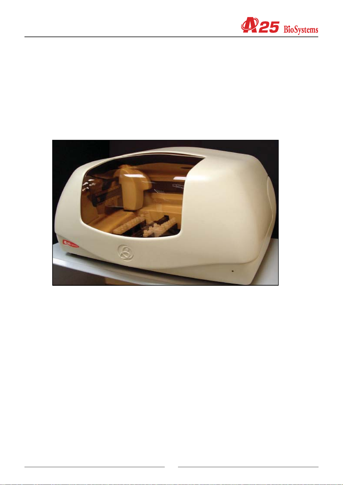
TheA25 analyzer is an automatic random access analyzer specially designed for performing biochemical and turbidimetric
clinical analyses. The instrument is controlled on-line in real time from an external dedicated PC.
In each of the components of the A25 analyzer, BioSystems has used leading edge technology to obtain optimum
analytical performance, as well as taking into account economy, robustness, easy use and maintenance. A three-axis
Cartesian operating arm prepares the reactions. Dispensing is performed by means of a pump with a ceramic piston via
a detachable thermostatised needle with Fuzzy Logic control. A washing station guarantees that the needle is kept
perfectly clean throughout the process. The reactions take place in a thermostatised rotor in which absorbance readings
are taken directly by means of an integrated optical system.
This manual contains the information required for learning about, maintaining and repairing theA25 automatic analyzer.
It should be used by the Technical Service as a learning and consultation document for the maintenance and repair of the
instrument. Chapter 2 describes the different mechanical components that form the analyzer together with their functionality ,
and chapter 3 describes the electronic system. Chapter 4 describes the Service Program. All the adjustments and
checks of the analyzer are carried out through this program, which is independent from the application program (User
Program). The separation of both programs enable it to be maintained separately and the extensions and improvements
of one do not affect the other. The user does not have the service program. The Technical Service must install it on the
user’s computer in order to carry out the service requirements. Once said tasks have been carried out, the Technical
Service must uninstall the program. Chapter 5 offers instructions for the different maintenance, repair and cleaning
operations that can be carried out by the Technical Service. The annexes contain a summary of the technical specifications
of the analyzer, the adjustment margin tables, the lists of accessories and spares, a list of software versions and their
compatibility and a software troubleshooting guide.
1.1. GENERAL DESCRIPTION OF THE ANALYZER
The A25 analyzer is made up of three basic components: the operating arm, the dispensing system and the reading and
reactions rotor. The electronic system of the instrument controls said components and communicates with the external
9
Service manual
computer containing the application program. Through this program, the user can control all the operations of the analyzer.
The analyzer may be fitted with the option of an external module for measuring ion concentration.
1.1.1. Operating arm
This is a three-axis XYZ Cartesian mechanism. The X and Y axes move the dispensing needle over the analyzer horizontally
and the Z axis moves it vertically . It is operated by three step-by-step motors. In each 15-second preparation cycle, the
operating arm performs the following actions: first of all, it sucks in the reagent from the corresponding bottle. Next, the
needle is washed externally in the washing station and sucks in the sample from the corresponding tube. It is washed
externally again and dispenses the sample and the reagent into the reactions rotor. Finally, it is exhaustively washed
internally and externally before proceeding with the next preparation. The arm has a system for controlling vertical
movement to detect whether or not the needle has collided into anything on descending. If a collision occurs, as may be
the case if, for example, a lid has been left on a bottle of reagent, the arm automatically restarts, verifies the straightness
of the needle and continues working issuing the corresponding alert to the user. A vertical axis retention system prevents
the needle from falling in the case of a power cut, avoiding injury from the needle to the user or the needle being bent by
an attempt to move the arm manually . The operating arm only makes the preparations if the general cover of the analyzer
is closed. If the cover is raised while it is functioning, the arm automatically aborts the task in progress and returns to its
parked position to avoid injury to the user.
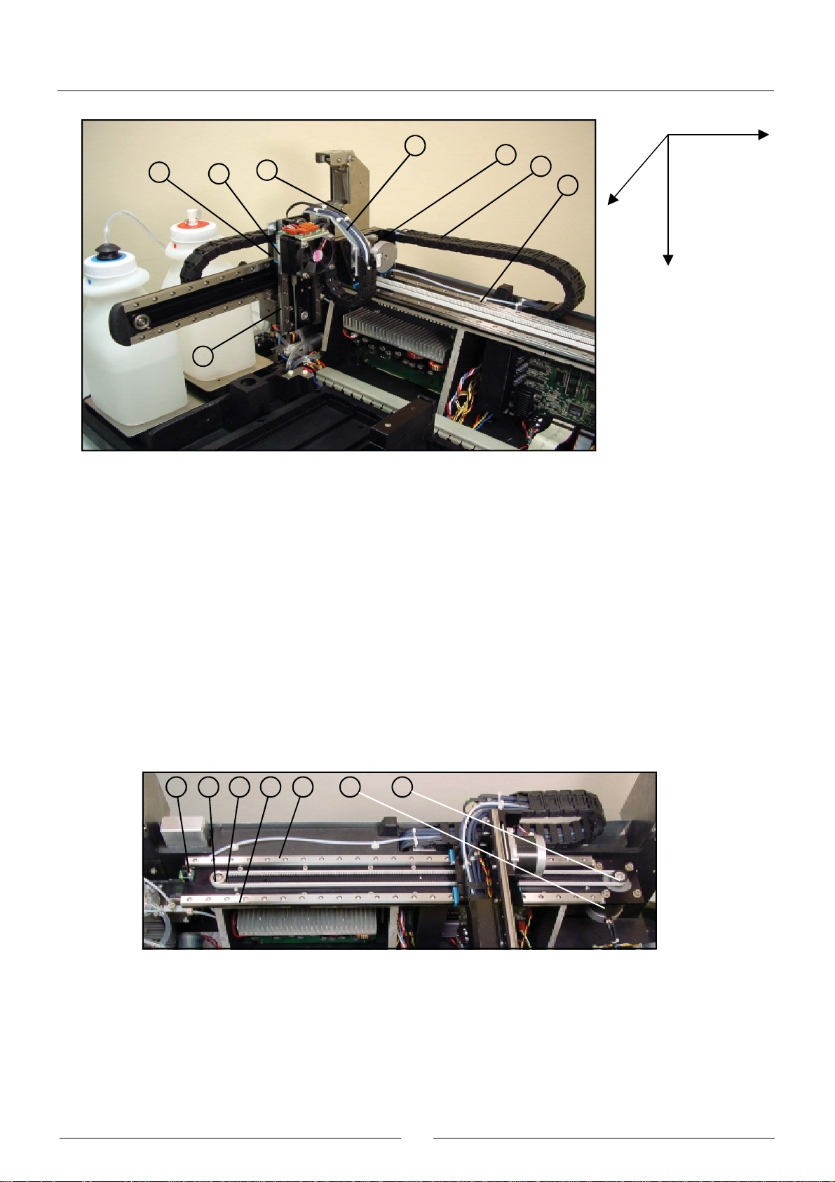
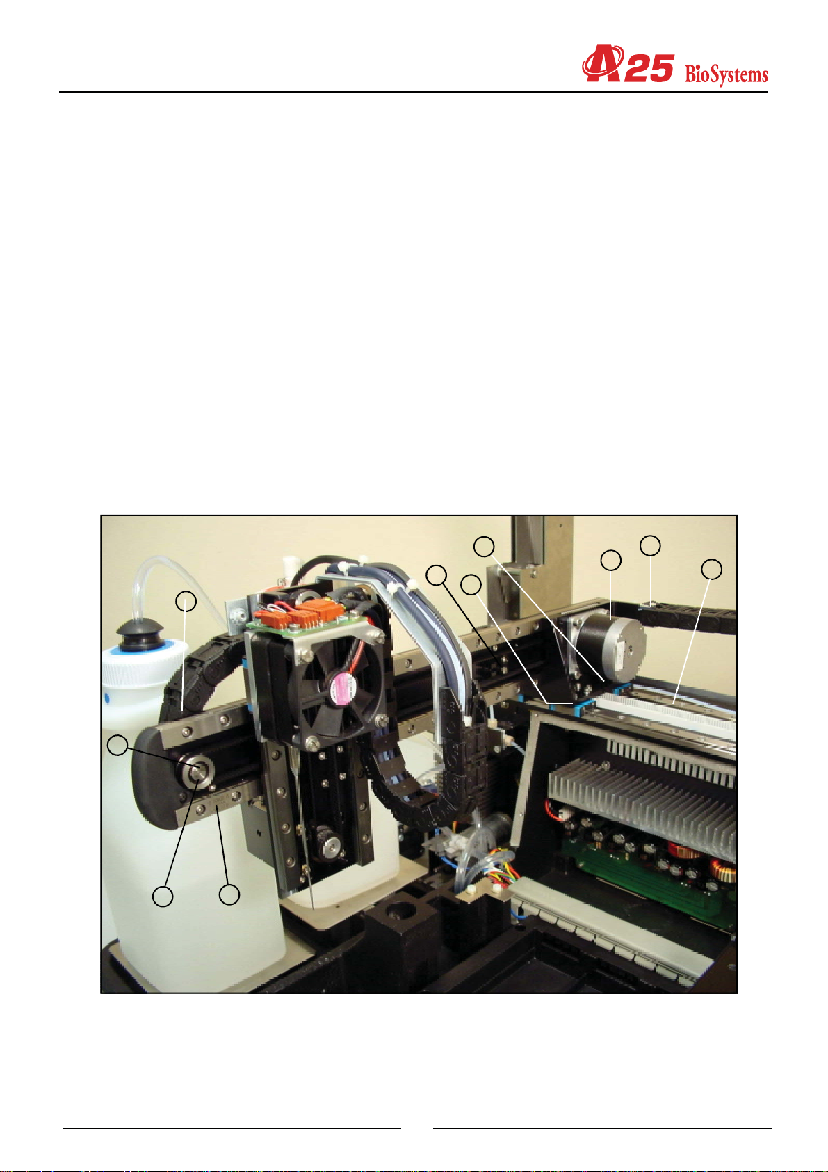
1.1.2. Dispensing system
This system consists of a thermostatised needle, supported and displaced by an operating arm and connected to a
dispensing pump. The needle is detachable to enable cleaning and replacement. The analyzer has capacity level detection
to control the level of the bottles and tubes and prevent the needle from penetrating too far into the corresponding liquids,
thus minimising contamination. An automatic adjustment system informs the user if the needle is not mounted or if it is
too bent. The needle has a sophisticated Peltier thermostatisation system, with Fuzzy Logic control, capable of
thermostatising the preparations at approximately 37º in less than 6 seconds. Dispensing is carried out by means of a
low maintenance ceramic piston pump driven by a step-by-step motor. It is capable of dispensing between 3 and 1250 L.
The exterior of the needle is kept constantly clean by means of a washing station, which consists of a font specially
designed to clean and dry the needle, integrated in the racks tray . A system of diaphragm pumps supplies the font with
distilled water and transports the waste to its container.
The A25 analyzer has a tray with 6 free positions for racks of reagents or samples, plus three fixed positions for bottles
opposite the washing station. Each reagents rack can carry up to 10 reagents in 20 ml or 50 ml bottles. Each samples
rack can contain up to 24 tubes of samples. The samples can be patients, calibrators or controls. The analyzer can be
configured to work with 13 mm or 15 mm diameter tubes of samples with a length of up to 100 mm or with paediatric
wells. Any possible configuration of racks can be mounted from 1 rack of reagents (10 reagents) and 5 racks of samples
10
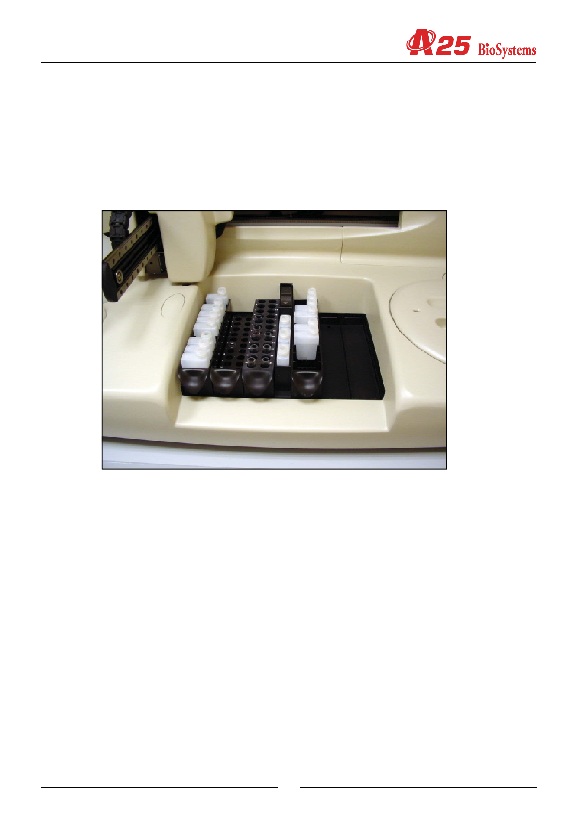
(120 samples) to 5 racks of reagents (50 reagents) and 1 rack of samples (24 samples). Any reagent may be placed in
the fixed positions, but it is recommendable to use them for the bottles of distilled water, saline solution for the automatic
pre-dilutions and washing solution. The rack tray detects and identifies the type of racks. In this way, if the physical
disposition of the racks does not coincide with that programd on the computer, the analyzer alerts the user.
On the left of the analyzer are the waste and distilled water containers. The analyzer constantly controls the level of these
containers and issues the appropriate alerts if the distilled water is nearly empty or if the waste container is full.
1.1.3. Reactions rotor and reading
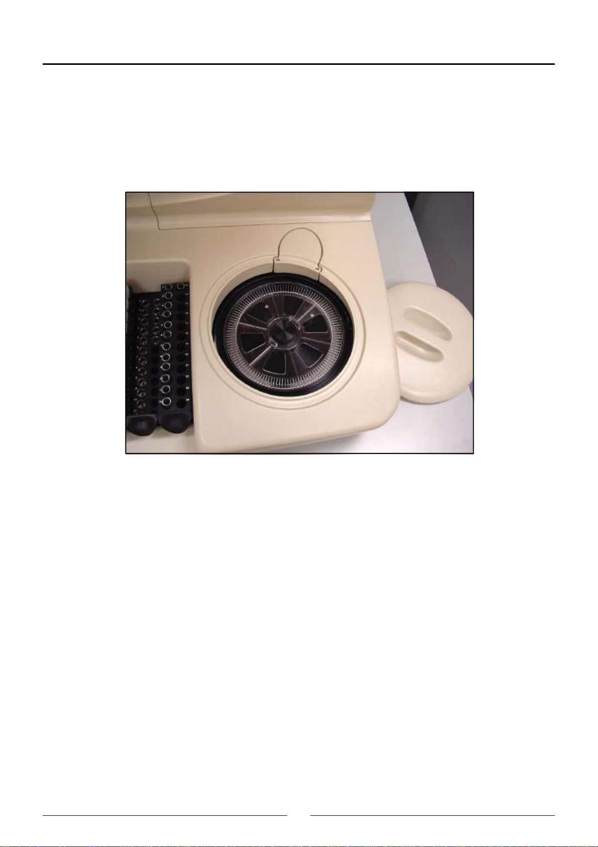
The preparations are dispensed in an optical quality methacrylate reactions rotor thermostatised at 37ºC. The optical
absorbance readings are taken directly on this rotor. Each reaction can be read for 15 minutes. The readings are taken
as they are programd in each measurement procedure. The reaction wells have been designed to enable the mixture of
the sample and the reagent during the dispensing. Each rotor has 120 reaction wells. The length of the light path is 6 mm.
The minimum volume required to take the optical reading is 200L. The wells have a maximum useful capacity of 800L.
When the reactions rotor is completely full, the user must change it with one that is empty , clean and dry. The reactions
rotors can be reused up to 5 times if they are carefully cleaned immediately after use. TheCleaning the semi-disposable
reactions rotor section in the User’s Manual describes how to clean the rotors. The user has a test in the computer
program, which he or she may use to check the condition of the rotor. The rotor is driven by a step-by-step motor with a
transmission.A Peltier system with PID control thermostatises the rotor at 37ºC.
An optical system integrated in the rotor takes the readings directly on the reaction wells. The light source is a 20 W
halogen lamp. The detector is a silicon photodiode. The wavelength is selected by a wheel with 9 positions available for
optic filters. The filters are easily changed by the user from the exterior of the analyzer, without the need for disassembling
the filter wheel. A step-by-step motor positions the wheel. The optical system is capable of taking 5 readings per second,
with or without a filter change in between. The light beam of the lamp passes through a compensated interferential filter
to select the desired wavelength and through focalisation lenses. It then passes through the rotor well and finally reaches
the photodiode, where the light signal is turned into an electric signal. A sophisticated analogical digital integratorconverter system converts the electric signal into a digital value with which the analyzer obtains the absorbance values.
11
Service manual
The optical system continues to work when the general cover of the analyzer is open, whereby the analyzer can continue
to take readings while the user handles, for example, the sample tubes or the reagent bottles. The rotor cover must be in
place for the optical system to work correctly. A detector tells the analyzer of the presence of the cover. The analyzer
aborts the readings if the user removes the rotor cover while the optical system is taking photometric measurements. If
the rotor is not covered, the analyzer informs the user so that he or she places the rotor cover when it sends samples to
be analyzed.
1.1.4. Electronic system
The described components are controlled by an electronic system based on a microprocessor.The microprocessor has
two external communication channels that make it possible to link up the instrument to the computer containing the
application program and to an optional external module for measuring ion concentration. The electronic system is made
up of the following independent boards:
- Microprocessor board
- Photometric system board
- Needle conditioning board
- Racks detection board
- Front indicator board
- Power supply board
- Communications board
1.1.5. Application program
The application program makes it possible to control all the operations of the analyzer. From this program, the user can
monitor the state of the analyzer and the work session, program parameters, e.g. technique parameters, prepare the
work session, prepare results reports, configure different analyzer options, activate various test utilities, prepare and
maintain the instrument and carry out internal quality control processes. The purpose of this manual is not to explain the
functioning of the user program. For detailed information to this regard, please consult the User’s Manual included with
the analyzer.
12

1.2. FUNCTIONING OF THE ANALYZE R
TheA25 analyzer is an automatic random access analyzer specially designed for performing biochemical and turbidimetric
clinical analyses. The analyzer performs patient-by-patient analyses and enables the continual introduction of samples.
The analyzer is controlled from a dedicated PC that is permanently communicated to the instrument. The program,
installed on the computer, keeps the user constantly informed of the status of the analyzer and the progress of the
analyses. As results are obtained, the computer shows them to the user immediately.
When a Work Session is begun, the analyzer proposes performing the blanks, calibrators and controls programd for the
measurement procedures it is to carry out. The user may choose between performing the blanks and the calibrators or
not. If they are not performed, the analyzer uses the last available memorised data. The controls can also be activated or
not. During a session, while the analyzer is working, the user can introduce new normal or urgent samples to be
analyzed. Each time a new sample is added, the analyzer automatically proposes the possible new blanks, calibrators
or controls to be performed. A work session can remain open for one or more days. When a session is closed and
another new session is opened (Reset Session), the analyzer again proposes performing the blanks, calibrators and
controls. It is recommended that the session is reset each working day.
The analyzer determines the concentrations of the analytes based on optical absorbance measurements. To measure
the concentration of a certain analyte in a sample, the analyzer uses a pipette to take a specific volume of the sample
and the corresponding reagent, quickly thermostatises them in the needle itself and dispenses them into the reactions
rotor. The very dispensing speed together with the geometry of the reaction well causes the mixture to be shaken and the
chemical reaction begins. In the bireagent modes, the reaction begins when the analyzer later dispenses a second
reagent in the same reaction well. The reactions can be biochemical or turbidimetric. In both cases, the reaction or the
chain of reactions produced generate substances that attenuate certain wavelengths, either by absorption or by dispersion.
Comparing the light intensity of a certain wavelength that crosses a well when there is a reaction and when there is not
a reaction can determine the concentration of the corresponding analyte. This comparison is quantified with the physical
magnitude called absorbance. In some cases, the concentration is a direct function of the absorbance, and in other
cases, it is a function of the variation of the absorbance over time, depending on the analysis mode.
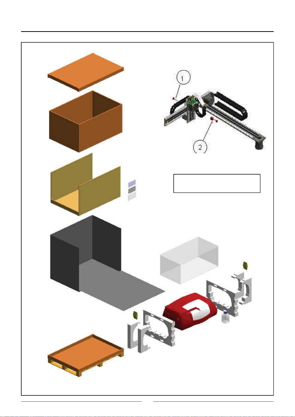
1.3. TRANSPORT AND RESHIPMENT OF THE ANALYZER
If the analyzer is to be reshipped or moved using a transport vehicle, it is important to block the operating arm and use the
original packaging to ensure that the apparatus is not damaged. To package the instrument, we recommend you follow
the following instructions: (on the unpackaging instructions sheet).
13
Service manual
Screws (1) and (2) are for blocking
and unblocking the arm mechanism.
14

2. MECHANICAL COMPONENTS
2.1. Instrument breakdown
The physical structure of the analyzer can be broken down as follows:
· Operating arm
- X guide.
- X carriage.
- Y carriage. This includes the spring and encoder of the Z carriage.
- Z carriage. This is the carriage carrying the thermostated needle. It includes the electronic needle conditioning
board.
- Cable carrier chains. These contain the electrical hoses of the arm and the dispensing tube.
· Dispensing system.
- Thermostated probe.
- Dispensing pump.
- Tubes and containers.
- Container level control scales.
- Racks tray with integrated washing station. This includes the electronic racks detection board.
- Washing pumps.
· Reactions rotor with integrated optical system.
- Thermostated rotor and photometric system. This contains the electronic photometric system board.
- Lighting system.
· Back covers
· Main cover hinges.
· Base. This houses the electronic boards of the microprocessor, the power supply and the front indicator .
· Housings.
- Back housing.
- Front housing. This houses the optical and rotor covers.
- Arm housing.
- Main cover.
The following is a brief description of each of the mechanical components that make up the analyzer.
2.2. Description of the mechanical components
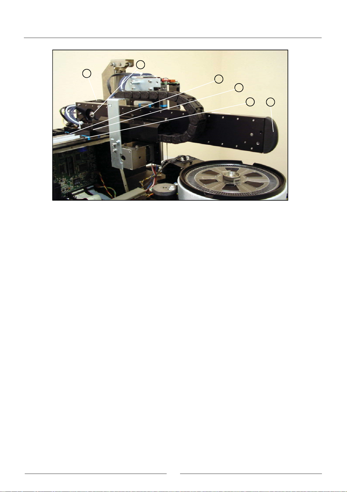
2.2.1. Operating arm
This mechanism positions the dispensing needle appropriately during the preparation of the analyses. An encoder
checks the vertical movement of the needle and a spring automatically stops it from falling in the case of a power
cut. The dispensing tube and the electrical hoses of the arm are housed in cable carrier chains, which guide them
appropriately . A housing unit covers the Y and Z carriages.
(1) X GUIDE
(2) X CARRIAGE
(3 ) Y CARRIAGE
(4 ) Z CARRIAGE
(5 ) CABLE CARRIER CHAIN
(6 ) TEFLON DISPENSING TUBE
(7 ) ELECTRICAL HOSES
(8 ) Y CARRIAGE CHAIN SUPPORT COVER
15
Service manual
7
8
4
6
2
5
1
X
Y
Z
3
The Z carriage (4) supports the thermostated needle and can be displaced over the Y carriage (3), which, in turn, can
be displaced over the X carriage (2), which, in turn, can be displaced over the X guide (1). In this way , the needle can
be displaced in the three Cartesian directions of X, Y and Z. The cable carrier chain (5) houses the Teflon dispensing
tube (6) and all the electrical hoses (7) of the arm. The support cover (8) guides the cable carrier chain of the Y
carriage along the X carriage.
2.2.1.1. X guide
(1) X GUIDE PROFILE
(2) X TRACK RAILS
(3) X START PHOTODETECTOR
(4) RETURN PULLEY
(5) BEARING
(6) OPERATING PULLEY
(7) X MOTOR
34521 7 6
This consists of an aluminium profile (1) which holds the steel rails (2) on which the X carriage runs. The photodetector
(3) indicates the position of the start of the movement of the X carriage. The motor (7) operates the belt of the X
carriage by means of the pulley (6). The pulley (4), fitted on the bearing (5), returns the belt operated by the motor.
16
2.2.1.2. X carriage
(1 ) X CARRIAGE BODY
(2 ) Y GUIDE PROFILE
(3 ) Y TRACK RAILS
(4) Y START PHOTODETECTOR
(5) X START DETECTION BARRIER
(6) LINEAR SLIDE UNIT
(7) NOTCHED BEL T
(8) BELT FASTENING
(9) RETURN PULLEY
(10) BEARING
(1 1) OPERATING PULLEY
(12 ) Y MOTOR
(13 ) X CARRIAGE CHAIN SUPPORT COVER
(14) X CARRIAGE CHAIN TERMINAL
(15 ) Y CARRIAGE CHAIN TERMINAL
(16 ) Y GUIDE RUBBER PROTECTION
10
8
4
1
12
13
7
3
9
2
17
Service manual
11
14
5
15
6
17
The X carriage can run over the X guide. The body of the X carriage (1) supports the aluminium profile (2) that holds the
steel rails (3) on which the Y carriage runs. The photodetector (4) indicates the start position of the movement of the Y
carriage. The motor (12) operates the Y carriage belt by means of the pulley (11). The pulley (9), fitted on the bearing (10),
returns the belt operated by the motor. The barrier (5) obstructs the X start photodetector when the X carriage reaches its
start position. The X carriage runs on its guide using the linear slide unit (6) fastened to the carriage body. The belt (7)
operates the X carriage. It is held to the body of the X carriage by means of the fastening (8). The support (13) holds the
terminal of the X carriage chain (14). The Y carriage chain terminal (15) is screwed directly onto the X carriage. The rubber
protection (16) prevents the Y guide from injuring the user.
2.2.1.3. Y carriage
(1 ) Z GUIDE PROFILE
(2 ) Z TRACK RAILS
(3) Y S TART DETECTION BARRIER
(4) Z START DETECTION BARRIER
(5) LINEAR SLIDE UNIT
(6 ) Y CARRIAGE CHAIN TERMINAL
(7 ) Z CARRIAGE CHAIN TERMINAL
(8) NOTCHED BEL T
(9) BELT FASTENING
(10 ) RETURN PULLEY
(1 1) BEARING
(12 ) OPERATING PULLEY
(13 ) Y CARRIAGE CHAIN SUPPORT COVER
(14) ENCODER PHOTODETECTOR
(15) ENCODER
(16) SPRING
(17) SPRINGFASTENING
(18 ) SUPPORT BODY
(19) COVER
(20) BONDING STRIP
(21) UNIT HOLDING
(22) Z MOTOR
18
11
2
4
10
13
7
9
8
12
17
14
20
13
5
16
17
7
22
15
18
19
21
19
Service manual
The Y carriage can run on the Y guide, which forms part of the X carriage. The aluminium profile (1), which holds the steel
rails (2) on which the Z carriage runs, constitutes the body of the Y carriage itself. The motor (22) operates the Z carriage
belt through the pulley (13). The pulley (11), fitted on the bearing (12), returns the belt operated by the motor.The barrier
(3) obstructs the X start photodetector when the X carriage reaches its start position. The barrier (4) obstructs the Z start
photodetector when the Z carriage reaches its start position. The Y carriage runs on its guide using the linear slide unit
(5) fastened to the carriage body . The belt (9) operates the Y carriage. It is held to the body of the Y carriage by means
of the fastening (10). The support (14) holds the Y and Z carriage chain terminals (7) and the arm housing. The springencoder unit of the Z carriage is made up of components (15)-(22). Part (19) is made up of the system body and contains
the self-raising spring (17) and the encoder (16) for the detection of vertical collisions. Part (18) joins the spring to the
encoder.The photodetector (15) detects the turn of the encoder when it runs along the Z carriage. The cover (20) closes
the system. The motor (23) has two shafts. Its back shaft has the encoder (16) and its front shaft has the operating pulley
of the Z carriage (13). Part (22) holds the system body (19) to the motor. The board (21) joins the system to the
instrument frame.
2.2.1.4. Z carriage
(1) ELECTRONIC NEEDLE CONDITIONING BOARD
(2 ) BOARD SUPPORT
(3) LINEAR SLIDE UNIT
(4 ) Z CARRIAGE CHAIN TERMINAL
(5 ) Z CARRIAGE BODY
(6 ) GEARED BEL T
(7) BELT FASTENING
(8) THERMOST A TED NEEDLE
2
1
4
3
8
5
7
6
20
The Z carriage holds the thermostated needle (9). It can run along the Z guide, which forms part of the Y carriage, by
means of the guide rollers (3) fastened to the carriage body (6). The belt (7) that operates the Z carriage is held to the
body of the carriage by means of the fastening (8). The terminal of the Z carriage chain (5) is screwed to the carriage
body . The electronic needle conditioning board (1) is screwed to the needle body and to the support plate (2). This board
contains the Z carriage start photodetector.
2.2.2. Dispensing system
The dispensing pump dispenses the preparations through the thermostated needle. The needle is washed internally and
externally at the washing station. The racks tray makes it possible to position the samples to be analyzed and the
required reagents. The level of the distilled water and waste containers is controlled by the analyzer by weight.
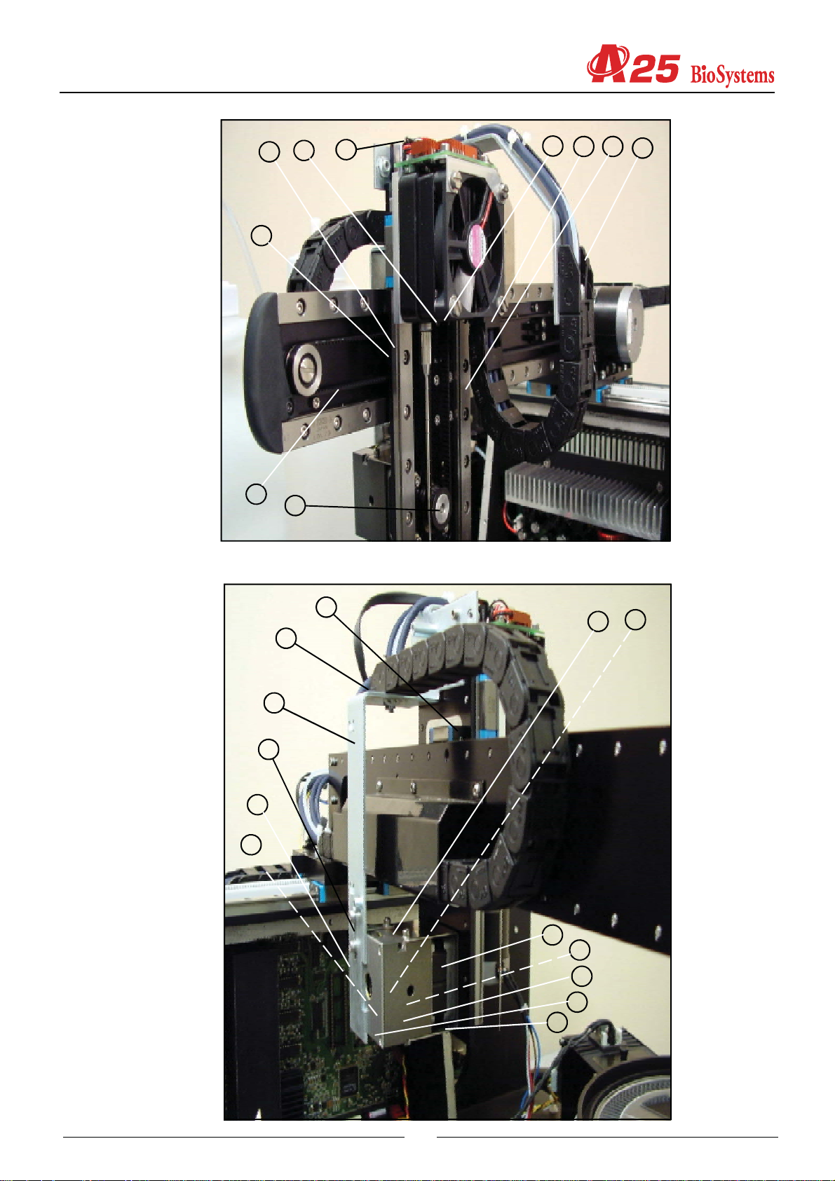
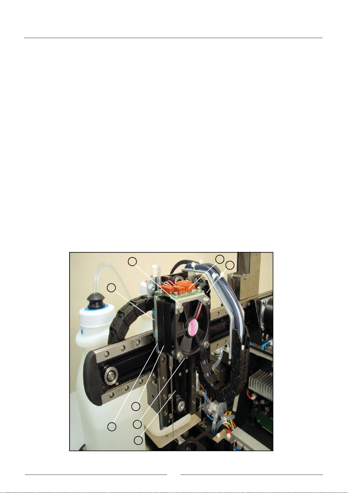
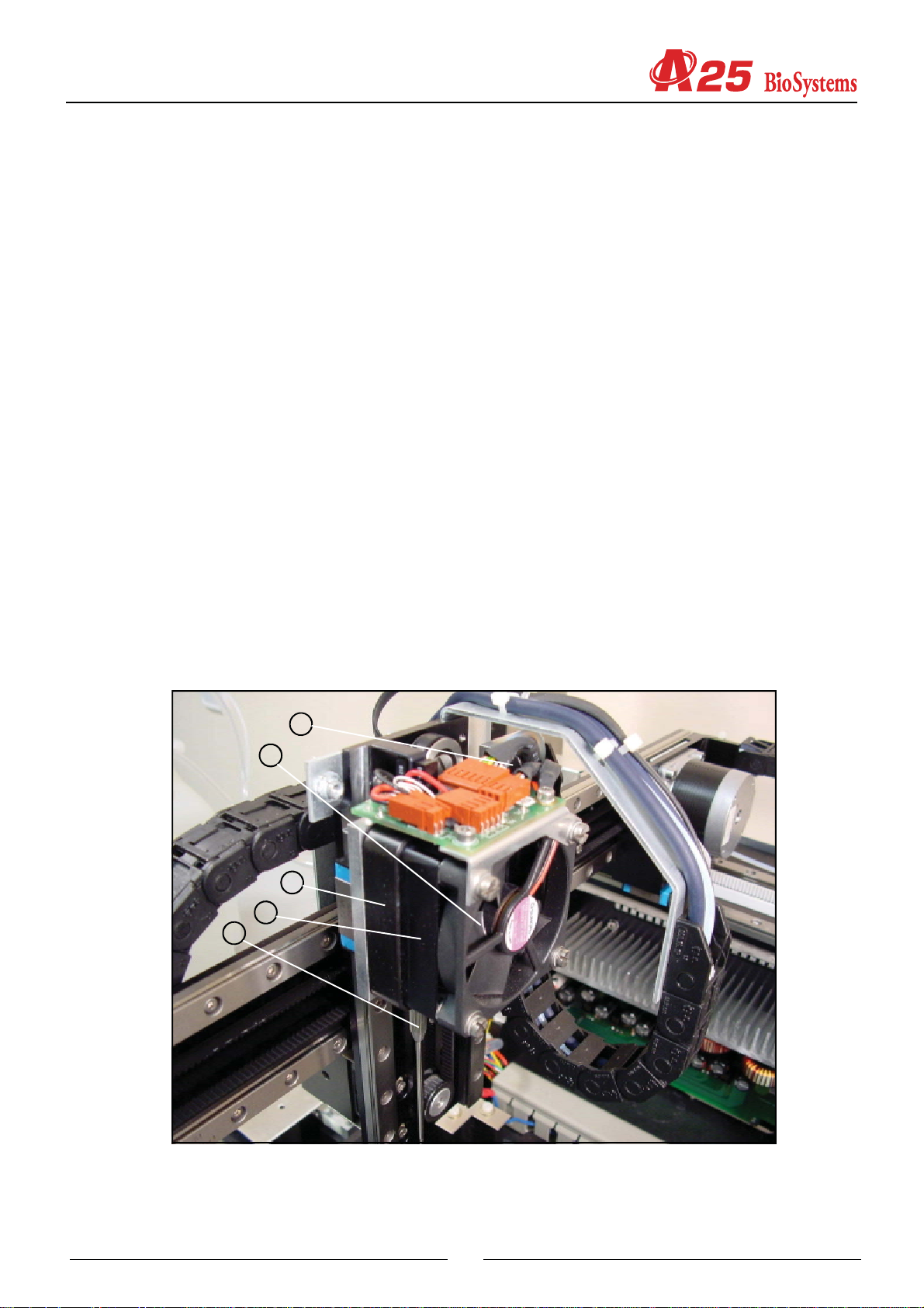
2.2.2.1. Thermostated needle
(1) PELTIER CELL
(2) THERMISTOR
(3) SPIRAL UNIT
(4) NEEDLEFASTENING FITTING
(5 ) REMOVABLE NEEDLE
(6) BODY
(7) FASTENING FITTING
(8) RADIATOR
(9) FAN
7
9
6
8
5
21
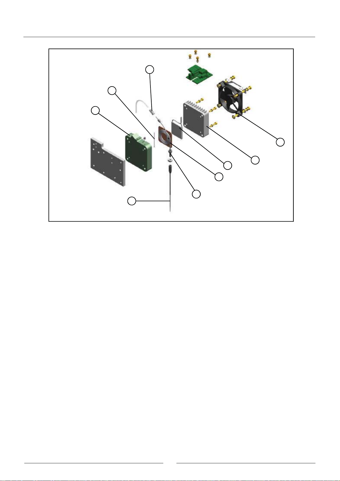
Service manual
7
2
6
9
1
8
3
4
5
The spiral unit (3) is made up of a spiral tube with fittings at both ends, welded to a copper plate. This unit is housed in
the interior of the plastic body (6). The thermistor (2) is held between these two parts and is the sensor used to control
the system temperature. The lower end of the tube of the spiral unit is firmly fastened to the body by the nut (4). The
removable needle (5) is screwed to this end of the tube. The upper end of the spiral tube is connected to the Teflon
dispensing tube of the operating arm. The fastening fitting (7) ensures said connection. The Peltier cell (1) that controls
the temperature is in contact with the copper plate of the spiral unit. The radiator (8), which is screwed to the plastic body ,
closes the system. The bolts that hold the radiator fan (9) are bushing bolts and are used to fasten the entire needle unit
to the Z carriage of the operating arm.
2.2.2.2. Dispensing pump
(1) BODY
(2) FLUIDIC CHAMBER
(3) SEAL
(4 ) SEAL SUPPORT
(5) CERAMIC PISTON
(6) PISTON SUPPORT
(7) TRANSMISSION PROTECTOR
(8) START DETECTION BARRIER
(9) WORM
(10) AXIAL BEARING
(11) MOTOR
(12) START PHOTODETECTOR
(13 ) PUMP SUPPORT
(14) PUMP FITTING
(15 ) PUMP-ELECTROVALVE TEFLON T UBE
(16 ) 3-CHANNEL ELECTROVALVE
(17) ELECTROVALVE FITTING
22
15
16
14
13
2
17
5
3
1
15
14
17
16
5
13
4
2
3
7
6
8
1
12
10
9
11
23
Service manual
The aluminium body (1) joins the different components that make up the pump. The transparent methacrylate fluidic
chamber (2) makes it possible to observe the flow of liquid through the pump. The support (4) fastens the seal (3) to the
chamber.The ceramic piston (5) dispenses by displacing a certain volume of liquid in the chamber. The plastic protection
(7) prevents the pump transmission from getting wet if the seal fails. The piston is adhered to the support (6), which
moves alternatively by the rotation of the worm (9) fixed to the motor shaft (11). The barrier (9), joined to the piston
support, obstructs the photodetector (12) when the piston reaches its start position. The axial bearing (10) prevents any
longitudinal displacement of the motor shaft for greater precision in the dispensing operation. The 3-channel electrovalve
(16) makes it possible to connect the pump chamber to the distilled water container or to the thermostated needle. The
support (13) makes it possible to fasten the pump and the electrovalve to the analyzer. The Teflon tube (15) connects the
chamber to the electrovalve. It is connected to each of these components by the fittings (14) and (17).
2.2.2.3. Tubes and containers
(1) WATER CONTAINER
(2) WATER CONTAINER LID
(3) WATER CONTAINER TUBES FASTENING
(4) WATER CONTAINER TEFLON TUBE
(5) TEFLON TUBE FIL TER
(6) ELECTROVALVE FITTING
(7) WATER CONTAINER PVC TUBE
(8 ) PVC TUBE FILTER
(9 ) WASTE CONTAINER
(10) WASTE CONTAINER LID
(1 1) FAST COUPLING FITTING
(12 ) WASTE CONTAINER PVC TUBE
(13) GROMMET
10
13
11
12
4 7
3
2
1
6
9
24
5
8
The Teflon tube (4) connects the distilled water container (1) to the electrovalve of the dispensing pump. This tube is
installed at the end of the filter container (5). It is connected to the electrovalve of the dispensing pump through the fitting
(6) The PVC tube (7) connects the distilled water container to the diaphragm pump of the washing water. This tube is
installed at the end of the filter container (8). Both water tubes pass through the rubber piece (3) in the lid (2) of the
container, which fastens them in position. The PVC tube (12) connects the waste extraction diaphragm pump to the
waste container (9). The waste container lid (10) has a fast coupling fitting (11) with automatic drip-proof closing when
disconnected. All the tubes pass into the interior of the analyzer through the rubber grommet (13).
2.2.2.4. Container level control scales
(1 ) LOAD CELL
(2 ) BASE SUPPORT
(3) BASE
(4) ADJUSTABLE MAXIMUMS
4
3
1
2
25
Service manual
The analyzer has two scales to control the level of the distilled water and waste containers by weight. Each of these
scales has a load cell (1) as a weighing component. One of the ends of the cell is fastened to the base of the instrument.
The support of the base (2) is screwed to the other free end. The base (3) is the stainless steel board on which the
containers stand. The base of the analyzer has 4 adjustable maximums (4) for regulating the maximum allowed deformation
of the load cell. The maximums prevent the cells from deteriorating if the user puts the containers on the scales in a
brusque manner.
2.2.2.5. Racks tray with integrated washing station
(1) TRAY
(2) WASHING ST A TION
(3 ) WASHING STA TION COVER
(4) LEVEL DETECTION SHEETING
(5) ELECTRONIC RACKS DETECTION BOARD
(6 ) WASHING WATER P VC TUBE
(7 ) WASTE EXTRACTION PVC TUBE
2
3
5
1
6
4
7
The plastic injection tray (1) is fastened directly to the base of the instrument. In the centre is the stainless steel washing
station (2), covered by the lid (3). The sheeting (4) enables the detection of the level of the dispensing needle. The
electronic board (5) detects the rack type placed in each of the 6 positions of the tray. The PVC tube (6) connects the
washing station to the flow volume limiter of the washing pump. The PVC tube (7) connects the washing station drain to
the waste extraction pump.
26
2.2.2.6. Washing pumps
(1 ) WASHING WATER diaphragm PUMP
(2) PUMP-ELECTROVALVE PVC TUBE
(3 ) 2-CHANNEL ELECTROVALV E
(4) FITTINGS
(5) ELECTROVALVE-LIMITER PVC TUBE
(6 ) FLOW VOLUME LIMITER
(7 ) WASTE EXTRACTION diaphragm PUMP
(8) SUPPORT
3
4
1
2
8
567
The needle washing system has two diaphragm pumps, one for the washing water (1) and another for waste extraction
(7). The PVC tube (2) connects the washing pump to the 2-way electrovalve (3), which is used to prevent the washing
station from unloading and to establish the precise amount of washing water. The PVC tube (5) connects the electrovalve
to the flow volume limiter (6). The electrovalve has stainless steel fittings for the connection of the PVC tubes. The
support (8) fastens the pumps and the electrovalve to the base of the instrument.
2.2.3. Reactions rotor with integrated optical system
The reactions rotor is thermostated at 37ºC. The optical system, made up of a lighting system and a photometric system
takes the readings directly on the rotor reaction wells. The lighting system has a halogen lamp, a filter wheel for the
selection of the wavelength and various lenses to form the appropriate beam of light. The photometric system contains a
silicon photodiode and the corresponding electronics to obtain a digital value that is proportionate to the light intensity
received.
27
Service manual
2.2.3.1. Thermostated rotor and photometric system
(1) METHACRYLATE ROTOR
(2) HEATING CHANNEL
(3) THERMAL INSULATION OF THE HEATING CHANNEL
(4) PELTIER CELLS
(5) RADIATORS
(6) THERMAL INSULATION BUSHES
(7 ) ROTOR FASTENING SCREW
(8) ROTOR CENTERER
(9 ) THERMAL INSULATION OF THE GEAR SUPPORT
(10 ) GEAR SUPPORT
(11 ) START PHOTODETECTOR
(12) ROTOR SHAFT
(13 ) BEARINGS
(14 ) ROTOR PULLEY
(15 ) GEARED BELT
(16) MOTOR SUPPORT
(17) MOTOR SPACER
(18) MOTOR
(19 ) MOTOR PULLEY
(20 ) PHOTOMETRIC SYSTEM SUPPORT COVER
(2 1 ) LEAKPROOF SEAL
(22 ) LOWER PHOTOMETRIC SYSTEM SUPPORT COVER
(23) PHOTODIODE GRILL CENTERER
(24 ) PHOTOMETRIC SYSTEM BOARD
(25 ) PHOTODIODE SPACER
(26) ROTOR GRILL
(27 ) TEMPERATURE PROBE
(28 ) THERMAL INSULATION OF PROBE
(29) COVER DETECTOR
(30) EARTH CONNECTION
(31 ) DRAINAGE TUBES
(32) COLUMNS
18
28
17
16
8 1
7
2
5
3
32
21
20
29
25
28
27
7
1
8
20
21
2
3
30
29
28
27
9
12
11
29
13
10
24
22
23
26
18
17
Service manual
6
32
5
14
15
16
19
4
31
The dispensing system dispenses the reagents and the samples in the methacrylate rotor (1). The optical system
measures the absorbance directly on the rotor wells. The aluminium heating channel (2) surrounds the rotor and keeps
it at 37ºC. The channel is thermally insulated from the exterior by means of the molded expanded polystyrene insulation
(3). The Peltier cells (4), with their respective radiators (5), act on the channel to control the temperature. The screws that
fasten the radiators are thermally insulated from the former by the bushes (6). The sensor used to control the temperature
is the probe (27), which is thermally insulated from the exterior of the channel by means of the sleeve (28). The methacrylate
rotor is fastened to its centerer (8) by means of the screw (7). The centerer is fastened to the rotor (12), which is mounted
on bearings (13) in the gear support (10). This support is screwed to the heating channel. The plastic part (9) thermally
insulates both parts from each other. The barrier obstructing the photodetector (11) when the rotor reaches its start
position forms part of the centerer (8). The pulley (19), fastened to the motor (18), acts, by means of the belt (14), on the
pulley (14) fastened to the rotor. The gear ratio is 1:12. The spacer (17) makes it possible to move the motor on its
support (16) to adjust the belt tension correctly . The electronic board of the photometric system (24) is housed in a cavity
in the heating channel. The upper cover of this cavity (20) supports the electronic board. The seal (21) keeps the cavity
hermetically closed in the case of possible liquid spillage. The cavity is closed at the bottom by the cover (22). The
photodiode is welded onto the board on the spacer (25). The part (23) centers the photodiode with regard to the lighting
system and also acts as a grill to prevent the incidence of unwanted light. The grill (26) limits the light hitting the reactions
rotor. The detector (29) tells the analyzer if the rotor cover is in position or not. The part (30) connects the heating
30

CHANNEL to the instrument frame. The tubes (31) drain the rotor of any possible liquid spillage. The columns (32) fasten
the rotor to the base of the analyzer.
2.2.3.2. Lighting system
(1) BODY
(2 ) LAMP HOLDER
(3 ) HALOGEN LAMP
(4 ) LAMP HOLDER FASTENING
(5) FILT E RWHEEL
(6) FILTER HOLDER
(7) FILTER HOLDER NUT
(8) FILTER COVER
(9) MATCHED INTERFERENTIAL FILTERS
(10 ) FILTERWHEEL SHAFT
(1 1) BEARING
(12) START PHOTODETECTOR
(13) MOTOR
(14 ) PCX LENS SUPPORT
(15) DIAPHRAGM
(16 ) PCX LENS
(17) PCX LENS NUT
(18 ) LCP129 LENS SUPPORT
(19 ) LCP129 LENS
(20 ) LCP129 LENS FASTENING
(21 ) LCP125 LENS SUPPORT
(2 2) SLOT BETWEEN LENSES
(23 ) LCP125 LENS
(24 ) LCP125 LENS FASTENING
(2 5) FILTE RWHEEL WINDOW COVER
(2 6) SIDE COVERS
13
6
5
4
3
2
26
1
31

Service manual
(27) FAN
(28) FASTENING BRACKET
24
20
23
22
21
1
4
25
26
2
15
8
7
13
3
14
17
18
28
10
27
12
19
11
9
5
16
6
The aluminium body (1) is the structure that supports all the components of the lighting system. The lamp holder (2),
fastened to the body by means of the fastening system (4), keeps the halogen lamp (3) in position without the need for
adjustments. The filter wheel (5) has 10 positions for optical filters. Position 0 must always be taken up by a covered filter
(8). The other positions can be taken up by an interferential filter (9) or by other covered filters. No position in the wheel
must be left unoccupied. Each filter is fitted on a filter holder (6) and fastened to it by the nut (7). The filter holders can be
dismounted from the wheel by simply pulling on them. The cover (25) allows easy access to the filter wheel. The filter
wheel is fastened to the shaft (10). This shaft can be turned by the direct action of the motor (13). Its end is guided by the
bearing (11). The photodetector (12) indicates the start position of the wheel. The light from the lamp, limited by the
diaphragm (15), passes through the collimating lens (16) fastened to its support (14) by the nut (17). The light passes
through the filter wheel, which selects the desired wavelength, and passes through the lenses (19) and (23) and the slot
(22), which adapt the form of the light beam to the geometry of the rotor wells. These lenses are mounted on their
respective supports (18) and (21) and are fastened by parts (20) and (24), respectively. The system body is laterally
closed by the covers (26) and the fan (27) keeps it at a desired temperature. The lighting system is fixed to the rotor and,
by the bracket (28), to the base of the analyzer.
32

2.2.4. Back covers
Three metallic covers close the back of the instrument.
2.2.4.1. Connectors cover
(1) CONNECTORS SUPPORT COVER
(2 ) COM1 CONNECTOR (DB9 FEMALE OR USB)
(3 ) COM2 CONNECTOR OR AUXILIARY (DB9 MALE)
(4) VENTILATION GRILL
4
1
3
2
The metallic cover (1) supports the connectors (2) and (3) that connect the instrument to the PC. There are two connectors
marked as COM1 and COM2.
The COM1 is for connecting the computer and can be connected using an RS-232 cable or a USB cable.
The COM2 is an auxiliary communications channel.
2.2.4.2. Switch cover
(1 ) SWITCH SUPPORT COVER
(2) MAINS CONNECTOR
(3) SWITCH
(4 ) FUSE HOLDER
(5 ) ID LABEL
(6) VENTILATION GRILL
33

Service manual
1
6
3
4
2
5
The metallic support (1) supports the connector (2) for the network cable, the instrument switch (3) and the fuse
holder (4).
2.2.4.3. Electronics cover
(1 ) BACK COVER OF THE ELECTRONICS
(2) FAN GRILLS
(3) FANS
1
3
34
2

The metallic cover (1) supports the central fans (3) protected by the grills (2).
2.2.5. Main cover hinges
(1) HYDRO-PNEUMATIC SPR ING
(2) ARTICULATED STEEL STRUCTURE
(3 ) COVER OPEN PHOTODETECTOR (on right-hand hinge only)
2
3
1
The two hinges enabling the raising of the main cover of the analyzer consist of an articulated steel structure (2) operated
by a hydro-pneumatic spring (1). The right-hand hinge includes a photodetector (3) to detect whether or not the cover of
the analyzer is open or closed.
2.2.6. Base
(1 ) CAST ALUMINIUM BASE
(2 ) CABLE GUIDE CHANNEL
(3) NEEDLE VERIFICATION BRACKET
(4) AUXILIARY DEVICES CONDUIT COVER
(5) FASTENING FOR AUXILIARY DEVICES
(6 ) CLAMP SUPPORT
(7) X CARRIAGE CHAIN TERMINAL
(8) FAN GRILL
(9 ) FRONT COVER OF THE ELECTRONICS
(10 ) MICROPROCESSOR BOARD
(1 1 ) POWER SUPPLY BOARD
(12) FRONT INDICATOR BOARD
(13 ) ADJUSTABLE LEG
(14) LEGS
35

Service manual
14
4
53
11 6
1
79
2
10
8
13
12
The base (1) on which all the components of the analyzer are fastened is made of cast aluminium, machined and painted.
The plastic channel (2) carries the cable hoses of different components to the electronic boards of the microprocessor
(10) and the power supply (11). The metallic bracket (3) is used by the analyzer to check the state of the needle. The
metallic cover (4) closes the conduit for optional auxiliary devices at the bottom of the base. The support (6) makes it
possible to fasten the ends of the hoses of the operating arm by means of plastic CLAMPs. The terminal of the X carriage
chain (7) is screwed directly to the base. The grill (8) protects the lighting system fan. The metallic covers (9) (removed
to see the boards) close at the front of the electronic boards of the microprocessor and the power supply . The board (12)
contains the front LED indicator of the instrument and is fastened directly to the base. The instrument stands on 4 rubber
legs (14). The front right leg (13) is adjustable in height to adapt the instrument to the work surface.
2.2.7. Housings
(1) FRONT HOUSING
(2) REAR HOUSING
(3 ) MAIN COVER
(4) COVERWINDOW
(5 ) ARM HOUSING
(6 ) OPTICAL SYSTEM COVER
(7) ROTOR COVER
(8 ) AUXILIARY DEVICES HOUSING COVER
36

2
5
6
7
8
4
1
3
The front housing (1) is screwed to the base and can be removed very easily without the need for removing any other
analyzer component. The rear housing (2) is also screwed to the base. The main cover (3) is screwed to the hinges. The
methacrylate (4) makes it possible to observe the functioning of the analyzer with the cover closed. The housing (5)
covers the Y carriage and the Z carriage of the analyzer. The cover (6) gives access to the optical system, making it
possible to change the lamp and filters with ease. The cover (7) covers the reactions rotor and readings.
37

Service manual
3. ELECTRONIC SYSTEM AND FLUIDS
1. Description of the electronics of the A25 analyzer.
2. CPU Board (CIIM00006)
3. Power Supply Board (SP300 & CIIM00007)
4. Needle Board (CIIM00008)
5. Photometry Board (CIIM00009)
6. Racks Board (CIIM00010)
7. LED Board (CIIM00011)
8. Communications Board (CIIM00019)
9. Interconnection between boards
Description of the electronics of the A25 analyzer.
The electronics of the analyzer are made up of different boards located at different points in the analyzer and dedicated
to specific functions. Their different locations correspond to functionality and performance criteria for the functioning of
the analyzer.
There are 8 different boards, which correspond to:
CPU Board (CIIM00006)
Power Supply Board (SP300 & CIIM00007)
Needle Board (CIIM00008)
Photometry Board (CIIM00009)
Racks Board (CIIM00010)
LED Board (CIIM00011)
Communications Board (CIIM00019)
Varistor Board (I37008A)
3.1 CPU Board (CIIM00006)
This is the brain of the machine, containing the microprocessor (H8/3003), responsible for controlling all the components
of the machine. The board has different data storage systems using either static RAM (U21), FLASH memory (U18) or
EPROM (U20). The slot associated with the EPROM is used to check the functionality of the board and the recording of
the MONITOR program in the production phases of the analyzer. The other two memories are associated with the normal
functioning of the analyzer. The FLASH memory holds the application itself as well as different databases related to
factory settings, adjustments, state of the rotor and possible extensions to the application.
The U34 device also exists on the board. This is a logical programmable device (FPGA) dedicated to the control of
motors, mapped in register memory associated with end-of-run control, electrovalves, decoding of racks (CIIM00010),
level sensing and control of the photometry-associate board (CIIM00009).
The control of the motors acts directly on the sequencers corresponding to each of the analyzer axes
(U1,U3,U6,U8,U10,U12) and these, in turn, on the power drivers (U2,U4,U7,U9,U11,U13) to act on the motor. The sequencerdriver pair is made up of the integrated L297 and L298. The regulation of the current of each axis can be configured by
means of a DAC that sets the current set point independently (U5). The sequencers are supplied through the U17
regulator and the drivers take their supply through the J16 connector, which corresponds to the 36V input on the CIIM00006
board.
The action on the thermostatation systems of the analyzer (needle and rotor) is carried out through H-shaped bridges
based on MOS technology (U29 and U30) and controlled directly from the microprocessor. The heating elements are
connected to J27 (needle) and J28 (rotor), respectively .
38

Connector Function Pins
J1 Mo tor Z 1 - coil 1
2 - coil 1
3 - coil 2
4 - coil 2
J2 M o tor Y 1 - coil 1
2 - coil 1
3 - coil 2
4 - coil 2
J4 M o tor X s haft 1 - coi l 1
2 - coil 1
3 - coil 2
4 - coil 2
J5 Pump Motor 1 - coil 1
2 - coil 1
3 - coil 2
4 - coil 2
J6 F ilter Drum M otor 1 - coil 1
2 - coil 1
3 - coil 2
4 - coil 2
J7 Rotor Motor 1 - coil 1
2 - coil 1
3 - coil 2
4 - coil 2
J8 D iaphra gm Pump 1 - motor
2- motor
J9 3- way electrovalve 1 - c oil 1
2 - coil 1
J1 0 2- way electrovalve 1 - c oil 1
2 - coil 1
J15 The signal enabling level detection by the analyzer
1- Faston
needle is injected into the racks tray through this
connector.
J1 6 3 6 V voltage 1 - 36 V
2- GND
J1 7 12 V voltage 1 - GND
2 - 12 V analogical
3- GND
4 - 12 V peltier
5- GND
6 - 1 2 V valves
J1 8 5 V voltage 1 - Vcc
2- GND
3 - Enable
39

Service manual
Connector Function Pins
J19 Weighting system for waste and system liquid bottles 1 - V dc
2 - GND
3 - V+
4 - V5 - Vdc
6 - GND
7 - V+
8 - V-
J24 Rotor conne ctor
J2 5 Co m m unicatio ns B o a r d C onnection (C IIM 00019)
1 - Vdc
2 - Rotor cover
3 - Home rotor
4 - GND
5 - Vdc home rotor
6 - F ilter wheel home
7 - GND
8 - V d c F ilter wheel home
9 - Rotor thermostatation
10 - GND
11 - Analogic 12 V
12 - GND
1 - Vdc
2 - GND
3 - Tx0
4 - GND
5 - Rx0
6 - GND
7 - GND
8 - Tx1
9 - GND
10 - Rx1
J27 Needle P eltier
J28 Rotor P e ltier
J29 Needle B oard Interconnection (CIIM00008)
40
1 - peltier, red
2 - peltier,black
1 - peltier, red
2 - peltier,black
1 - GND
2 - Home Z
3 - Needle thermistor
4 - Needle level detector
5 - GND
6 - 12 V

Connector Function Pins
J30 Z a xis encoder 1 - Encoder detector
2 - GND
3 - Vdc
J31 X axis home 1 - Home
2 - GND
3 - Vdc
J32 Y axis home 1 - Home
2 - GND
3 - Vdc
J33 Ceramic pum p home 1 - Home
2 - GND
3 - Vdc
J34 Rack decoding board connection (CIIM00010) 1 - Detector 1
2 - Detector 2
.
.
24 - Detector 24
25 - GND
26 - Vdc
J35 Photometric board connection (C IIM00009) 1 - 12 V
2 - GND
3 - DVALID
4 - DCLK
5 - DO UT
6 - DXM IT
7 - RANGE2
8 - RANGE1
9 - RANGE0
10 - TEST
11 - CONV
12 - GND
13 - CLKAD
14 - GND
15 - GND
16 - Vdc
J36 LED board connection (CIIM000011) 1 - GND
2 - LED
3 - LED
4 - Vdc
J99 Fan 1 - 12V
2 - GND
41

Service manual
42

As for analogical circuitry on the board, the J19 connector corresponds to the input of the sensors for machine water and
waste control. These sensors are load cells and they are conditioned by U16 and associated components. The sensor
signal is linearised and amplified and is then redirected to the analogical-digital converters in the microprocessor. There
is also a circuit for conditioning the signal of the thermistor associated to the thermostatation of the rotor that is made up
of the U22 and U28 circuits. The signal used to detect the level is generated by U28. The injection of the signal is done
by J15 and it is collected through the cables that come from the analyzer needle and connect on J29.
There are also different integrated circuits for the encoding of the control signals for all the components that share the
data and address bus (U26, U23, U24 and U36), control signals inversion (U35).
The board has an acoustic alarm.
TP1 - VRAM
TP3 - LOW-LINE
TP4 - RESET
TP6 - WATCHDOG
TP12 - Needle level detector
TP13 - LSO
TP14 - RW
TP2 0 - CS_EPROM_L
TP2 1 - CS_RAM_L
TP2 2 - CSF2_L
TP2 3 - CSF1_L
TP2 4 - RD_L
TP 25 - CLK system (16 MHz)
TP 28 - LWR_L
TP 29 - HWR_L
TP 30 - Motor chopper frequency
TP 36 - Conditioned signal output from the rotor thermistor
TP37 - Analyzer cover
TP3 9 - Rotor cover
TP 40 - CS_FPGA_L
TP44 - INIT_L
TP 45 - DONE
TP4 6 - PROGRAM_L
TP4 7 - CCLK
TP48 - DIN
TP 50 - Z shaft motor vref
TP 51 - Y shaft motor vref
TP 52 - X shaft motor vref
TP 53 - Dispensation/aspiration pump motor vref
TP 54 - Filter drum motor vref
TP5 5 - Rotor motor vref
TP5 6 - IN1 Needle Peltier Driver
TP 57 - EF Needle Peltier Driver
TP5 8 - IN2 Needle Peltier Driver
TP 59 - IN1 Rotor Peltier Driver
TP 60 - EF Rotor Peltier Driver
TP 61 - IN2 Rotor Peltier Driver
43

Service manual
3.2 Power Supply Board (CIIM00007)
This is made up of 5 different switched voltage regulators that enable distribution of the power supply in accord with the
requirement of each subsystem.
Connector Function Pins
J1 5 V output and enabling of
power supply board
J2 Output voltage 12 V for lamp
supply
J3 36 V i nput from the SP300-36
power supply board
J4 36V an d 12 V output voltage.
Supplies voltage for motors,
electrovalv es and membrane
pumps and thermostatisation
systems.
J5,J6 Fan connection on the central
back cover.
1 - 5V
2 - GND
3 - ENABLE
1 - 12 V
2 - GND
1 - 36V
2 - NC
3 - GND
1 - 36V
2 - GND
3 - 12V Valves
4 - GND
5 - 12 V thermostatisation
6 - GND
7 - 12 V analogic
8 - GND
1 - 12V
2- GN D
TP36V - 36V voltage
TPGND - GND
TP1 - 5V digitals
TP2 - Lamp voltage from 11.7 V <12V
TP3 - 12V Analogicals
TP4 - 12V Valves and diaphragm pumps
TP5 - 12V thermostatation
The existing bridge is to enable the different supply voltages. It has the same function as the enable of the J1 connector.
List of LED diodes:
D3 - Indicates 5V activated
D4 - Indicates 12V lamp activated
D7 - Indicates 12V valves activated
D8 - Indicates 12V analogicals activated
D10 - Indicates 12V thermos activated
44

45

Service manual
3.3 Needle Board (CIIM00008)
This board conditions the thermistor signal associated with the thermostatation of the needle, the preamplification of the
level detection signal and the Z home. It receives, from the needle-fan unit associated with thermostatation, the Peltier
cell, the thermistor and the level signal detected by the needle itself.
Two sets of cables leave this needle and join this board with the CIIM00006-01 board (specifically with the J29 and J27
connectors) for its J1 and J2 connectors.
Connector Function Pins
J1 CPU board connection (CIIM00006) 1 - Fan control
2 - Home Z
3 - Thermistor
4 - Sensor level
5 - GND
6 - 12V
J2 CPU board connection (CIIM00006) for the Peltier 1 - Peltier
2 - Peltier
3 - Chassis
J3 Thermistor 1 - GND
J4 Peltier 1 - Peltier, red
J5 Fan 1 - Fan control
J6 Needle connection for level detection 1 - needle
TP1 - Needle signal
TP2 - Output preamplifier needle signal
TP3 - Output amplifier thermistor signal
TP4 - Thermistor
12V - 12V voltage
5V - 5V voltage
AGND - GND
2 - Thermistor
2 - Peltier, black
2 - 12V
46

3.4 Photometry Board (CIIM00009)
This board also has the heart of the absorbance measuring system for the samples to be analyzed. It is made up of a
photodetector and an associated analogical-digital conversion circuitry (DDC112).
Connector Function Pins
J3 Photometric board connection (CII M00009) 1 - 12 V
2 - G ND
3 - DVA L ID
4 - DCLK
5 - DO UT
6 - DXMIT
7 - RANGE2
8 - RANGE1
9 - RANGE0
10 - TES T
11 - CONV
12 - G ND
13 - CLKAD
14 - G ND
15 -G ND
16 - Vdc
JP1 - soldering bridge - Solder only if the local oscillator and the U4 and U5 flip-flop, respectively , are not present.
JP2 - soldering bridge - The same than JP1
JP3 - soldering bridge - joins together the analogical and digital ground
47

Service manual
3.5 Racks Board (CIIM00010)
This board decodes the rack type the analyzer has at each of the positions for said racks. It is made up of a battery of
photobarriers that allow or stop light passing through the rack identification tabs at logical levels the analyzer firmware
can handle.
Connector Function Pins
J1 CPU board conn ection (CIIM00006) 1 - Detector 1
2 - Detector 2
.
.
24 - Detector 24
25 - G ND
26 - Vdc
3.6 LED Board (CIIM00011)
This board indicates the different states of the analyzer. It is made up of a bicolor LED and the circuitry associated with
action.
Connector Function Pins
J36 LED board connection (CIIM000011) 1 - GND
2 - LED
3 - LED
4 - Vdc
D1 - Bicolor LED
48

3.7 Communications Board (CIIM00019)
This enables communication with the exterior of the analyzer through a USB channel or a RS232 channel. It also
includes an auxiliary RS232 channel for monitoring the functions of the analyzer during its execution.
Connector Function Pins
J1 LED board conn ection(CIIM000011) 1 - Vdc
2 - G ND
3 - Tx0
4 - G ND
5 - R x0
6 - G ND
7 - G ND
8 - Tx1
9 - G ND
10 - Rx1
CN1 - USB Connector
P1 - Main RS232 connector
P2 - Auxiliary RS232 connector
D1 - USB TX LED indicator
D2 - USB Rx LED indicator
3.8 Interconnection between boards
The following diagrams show the connections between the boards and the different components that make up the
analyzer.
49

Service manual
3.8 Auxiliar channel information
The rear left part of the instrument is where the communications cables are connected. There are two connections, the
COM1 and the COM2.
The COM1 is the main connection from the analyser to the computer. This connection should be always present to
analyser run propertly .
there are two connection types:
A - Cable type USB
B - Cable type RS-232
Only connect one cable type.
The labeled connector COM2 is the auxiliar connector.
This connector is used to communicate with a second serial port in the computer.The function of this cable is to monitor
the internal states of the analyser.
To show all this information, the user should execute the program: windows HyperTerminal and configure with the
following parameters:
Baud Rate: 38400
Número de bits: 8
Stop bits: 1
Paridad: none
Onces is configured and connected the cable, switch on the analyser. In this moment will appear in the HyperTerminal
screen information about the analysers mode and the different executes states. In the initializate mode, the analyser do
an internal checking for each element, if someone has any error then in the screen will show the element that fails. The
following lines shows an exemple of the instructions during an initialization, (this information could change with the
improvements of the firmware) :
50

BIOSYSTEMS A25
Firmware initialization
Firmware Version: A25 User V2.80
Serial Number: 831011284
FLASH functions transferred to RAM
Interrupt Vectors transferred to RAM
Interrupts enabled
Checking firmware integrity
Checking program checksum:
Checksum correct! Program Checksum=0xDF32 Size=439296
Checking A25 configuration checksum:
Checksum correct! Configuration Checksum=0x21C2 Size=250
Checking A25 configuration backup checksum:
Checksum correct! Configuration backup Checksum=0x21C2 Size=250
Loading A25 Configuration from FLASH
Configuration in FLASH is correct
Adjustments loaded:
Temperature correction for Rotor=-0.19
Temperature correction for Probe=-0.50
System Liquid Low Level=500 (0%)
System Liquid High Level=780 (100%)
Waste Low Level=724 (0%)
Waste High Level=984 (100%)
Sensitivity of level detection=70
Origin X=23
Origin Y=20
Origin Z=445
Tray Reference X=1349
Tray Reference Y=335
Washing station X=1349
Washing station Y=22
Washing station Z=275
Reactions Rotor X=2887
Reactions Rotor Y=678
Reactions Rotor Z=415
Rotor Distance between the dispensation point and the optic system=1427
Rotor Position correction regard to the dispensation point=7
Rotor Position correction regard to the optic system=-4
Filters Wheel correction=-4
Filters and their Integration Times:
Filter 1=000 Integration Time= 10ms ( 20) Reference Time= 10ms ( 19)
Filter 2=340 Integration Time= 70ms (136) Reference Time= 70ms (136)
Filter 3=405 Integration Time= 14ms ( 28) Reference Time= 14ms ( 27)
Filter 4=505 Integration Time= 15ms ( 29) Reference Time= 15ms ( 29)
Filter 5=535 Integration Time= 16ms ( 31) Reference Time= 16ms ( 31)
Filter 6=560 Integration Time= 13ms ( 26) Reference Time= 13ms ( 25)
Filter 7=600 Integration Time= 19ms ( 37) Reference Time= 19ms ( 37)
Filter 8=635 Integration Time= 14ms ( 28) Reference Time= 14ms ( 27)
Filter 9=670 Integration Time= 25ms ( 48) Reference Time= 25ms ( 48)
Filter 10=000 Integration Time= 10ms ( 20) Reference Time= 10ms ( 19)
Zmax Reference=194
- Pediatric Offset=0
- 13mm Offset=0
- 15mm Offset=0
- Reagent Offset=100
- Central Reagent Offset=0
A25 Mechanical History
- X axis: 1207 Steps
- Y axis: 1157 Steps
- Z axis: 1449 Steps
51

Service manual
- Rotor: 88 Steps
- Filter Wheel: 1771 Steps
- Ceramic Pump: 1418 Steps
- Washing Station Pump: 903 Cycles
- Washing Station Valve: 903 Cycles
- Ceramic Pump Valve: 1341 Cycles
- Lamp: 661 Minutes
A25 Statistics
- Biochemistry Tests: 0
- Turbidimetry Tests: 171
- Biochemistry Bireagent Tests: 0
- Turbidimetry Bireagent Tests: 0
- Predilutions: 0
- Initial/Final Washings: 0
- Washing Solution Washings: 0
- System Liquid Washings: 50
- New Rotor: 1
- Bireagent Contaminations Solved: 0
Detecting Main Board version (CIIM00006-XX)
Ok. Main Board version is CIIM00006-02/03
Configuration Load from X9279: STT= 3 RD=0 TD=1 GD=0
Setting racks layout
Tray Ref. X=1349 => Distance from tray reference to tray corner X=1082
Tray Ref. Y=335 => Distance from tray reference to tray corner Y=432
Absolute position of tray corner X=267
Absolute position of tray corner Y=-97
Generating Zmax Map:Ok
CPU settings: MDCR=c4;ABWCR=0;ASTCR=ff
BioSystems A25
Hello World
A25 MAGIC KEYS
H: Help
R: Rotor Temperature
P: Probe Temperature
S: Level Scales
A: Last A25 Stress Results
L: Actual Sensitivity of Level Detection
N: Enable Level Detection Debug
K: Power Supply On
Buzzer Control
B: Buzzer On
b: Buzzer Off
Encoder
E: Generate Encoder Error
I: Enable Encoder IRQ
Rotor Reading
1: Choose Filter +
2: Choose Filter 9: Start Rotor Readings
Notes: Use only in Service Mode
after a Base Line Test.
Rotor Read
1: Choose Filter +
2: Choose Filter User Mode Test
G: Test
Notes: Use only after a Worklist in
Stand By.
This tests dumps all the preparations
parameters received and the photometric
readings. Finally performs a general test
52

of the analizer.
After this test press New Rotor
for continue working.
DDC112/Photometry
D: Choose Mode
- DDC112 internal test mode
- DDC112 Photometry Mode
- Stop
+: Integration Time +0.5ms
-: Integration Time -0.5ms
Notes: Only works in Service Mode
This tests performs continuous
readings with the DDC112.
Remember stop the test for
continue working.
Caution: Dont't abuse of this functions while the
analizer is running.
CONNECTED WITH PC!
Rx s=0
Stand by mode!
Send Status
Rx s=1
Inicio modo servicio!
Hardware Initialization
Programming FPGA XCS30TQ144
- Clearing FPGA program memory: OK!
- Programing FPGA: OK
FPGA XCS30TQ144 is programmed
Initialization of level detection system
- Generating Sensitivity Map:Ok
- Programming X9279: .OK
Sensitivity is programmed
Initializating Motors
- Axis Z in HOME
- Axis Y in HOME
- Axis X in HOME
- ROTOR in HOME
- FILTERS WHEEL in HOME
- CERAMIC PUMP in HOME
Motors Initializated
Optics Initialization
- Filter correction=4
- Rotor correction=1113 Rotor Lect. correction=-4
- Used wells:28
- Check DDC112.OK (FPGA 8Mhz Clock: OFF)
- DDC112 test: OK! (Result => 0045140)
Optics Initializated
Generating Pattern: 1 1 1 1 1 1 1 1 1 0 0 0 0 0 0 0 0 0 0 0
Generating Gate: 0 0 0 1 1 1 0 0 0 0 0 0 1 1 1 1 1 0 0 0
OK
Z Axis Initialization
- Axis Z in HOME
Z Axis initializated
Programming the encoder: 0000| OK
Z Axis Initialization
- Axis Z in HOME
Z Axis initializated
Auto-Adjustment of the probe
- Positioning ARM
- Detecting X side: OK. The correction is X=Xcal+0
53

Service manual
- Detecting Y side: OK. The correction is Y=Ycal+-1
Auto-Adjustment of the probe is done
Peltier Cells and Drivers Test
- Probe Peltier Driver Test: Ok!
- Rotor Peltiers Driver Test: Ok!
Hardware Initializated
HC
Detecting the reactions rotor
- Filter 340nm Found! (1)
- The lamp doesn't need time for stabilization
- Rotor detected! (Average= 749967 Desvest=150577.36)
Send Status
Rx s=0
Rx service task
N=1 T=0 F=156 P1=0 P2=0 P3=0
End Service Recipe
Send service
Rx s=1
Rx service task
N=1 T=0 F=157 P1=0 P2=0 P3=0
End Service Recipe
Send service
Rx s=0
Rx service task
N=1 T=0 F=152 P1=0 P2=0 P3=0
End Service Recipe
E=>0
Send service
There are a few keys that work with the Hyperterminal, to press some keys the analyser give information about some
element, the following keys has the function:
H: Help, help, shows the help text
R: Rotor Temperature, shows the rotor temperature
P: Probe Temperature, shows the needle temperatare
S: Level Scales, shows the scales mesures in %
A: Last A25 Stress Results
L: Actual Sensibility of Level Detection
N: Activate additional information of level detection (only internal use)
K: Deactivate the power supply
B: Activate the buzzer
b: Deactivate the buzzer
E: Generate an encoder error (only internal use)
I: Activate the encoder interrupt (only internal use)
1: Increase the filter wheel position
2: Decrease the filter wheel position
9: Mesure the whole rotor, step by step
G: Once finish a work list, push the G and send to the hyperteminal more detailed
information of the work list managemnet
D: Show the mesure depending on the number of key pressed
1st press: activate the internal test DDC112, always show the same count number
2nd press: activate the normal mesure DDC112, show the count number mesured
3th press: stop the DDC112 mesure
+: Increase the integration time in 0.5ms
-: Decrease the intergration tie in 0.5ms
3.9 Boards interconnection
The following schematics shows the connection between boards and the differents elements has the analyser.
54

55

Service manual
56

57

Service manual
l
o
/
Y
ellow
CIIM00006-01
CIIM00007-02
POWER SUPPLY
DC PUMPS
3-WAY EV
2-WAY EV
PLMA00019
J17
1
3
4
5
62
J10
PLMA00022
CPU
4
2
0
0
0
A
M
L
P
J16
1
J9
J8
2
4
2
0
0
0
A
M
L
P
Verde/Green
PLMA00047
1
1
1
2
Negro/Black
Rojo/Red
Verde/Green
Negro/Black
Verde/Green
Negro/Black
Negro/Black
2
Amaril
Amarillo/Yellow
2
Azul/Blue
Azul/Blue
Azul/Blue
Negro/Black
2
1
5
3
4
6
8
7
J4
58

2345678
1
CPUBALAN
Z
A
SIDUO
S
/
A
STESCALEBALAN
Z
A
A
G
U
A
/
W
A
TERSCAL
E
123
4
Blanco/White
Blanco/White
Blanco/White
Blanco/White
Blanco/White
Marron/Brown
123
J18
123
CIIM00007-01FUENTED
EALIMEN
TACIONP
OWERSUPPL
Y
Azul/Blue
PLMA00025
PLMA00006
Rojo/Red
Azul/Blue
Verde/Green
21432143
Azul/Blue
Verde/Green
Rojo/Red
Azul/Blue
Verde/Green
Rojo/Red
2143
Rojo/Red
Azul/Blue
Verde/Green
Rojo/Red
W
RE
CIIM00006
PELTIER
ROTOR
J28 J19
2
1
PLMA00008
PLMA00008
59

Service manual
ROTOR
1
CIIM00006CP
U
CIIM00009
METRICBORADCIIM00019COMMUNI
CATIONS
RACKS BASE
12312
3
P
L
MA000
0
2
J25
PLMA00014
Rojo/Red
6
2
J
Negro/Black
Amarillo/Yellow
PLMA00035
D
/
A
P
E
A
T
D
R
E
O
V
C
O
T
R
C
T
D
E
E
R
O
T
T
E
C
E
J1
J35
PLMA00023
J34
J3
PHOTO
PLMA00010+PLMA00012
2345678
J15
J24
9
10
11
12
RACKS
PLMA00001
60

J36
112
2
PELTIER
TERMISTOR/
PLMA00042
PLMA00043
PLMA00044
PLMA00045
PLMA00046
Negro/Black
VENTILADOR / FAN
PUNTA / PROBE
HOME X
Rojo/Red
Negro/Black
Amarillo/Yellow
Rojo/Red
Negro/Black
2
1
J6
PUNTA / NEEDLE
CIIM00008
J1
1
2
3
4
5
Negro/Black
1
J5
J4
J3
Rojo/Red
Blanco/White
Blanco/White
J2
6
1
2
3
1
J31
2
3
PLMA00038
J29
CIIM00006
CPU
Marron/Brown
Verde/Green
Amarillo/Yellow
Gris/Gray
Rosa/Pink
Blanco/White
PLMA00029
Blanco/White
Verde/Green
Marron/Brown
1
2
J27
PLMA00028
LED
1234
Gris/Gray
Verde/Green
Blanco/White
Naranja/Orange
J1
CIIM00010
123456
61

Service manual
3.10 Schematic liquid circuit
62

4. SERVICE PROGRAM
The service program is used for the adjustment, checking and maintenance of the different components of the
analyzer. It is not supplied with the instrument, it is supplied to authorised technical services only . The personal of
the Technical Service must install it on the user’s computer in order to carry out the service requirements. Once
the tasks have finalised, the program must be uninstalled. To install the program, follow the instructions on the
installation CD ROM called Service. The original password for using this program isA25. The password can be
changed from the service program itself. If the service personnel forget the password, the original password can be
reinstalled by deleting the hidden filecode.a25 from the application directory and relaunching the program. Once
the password has been introduced, the analyzer serial number is given and the name of the operator is requested
(by default Operator1). Press the Accept button and the main program appears. The different functions of the
service program are classified in the following categories:
- Adjustments: These make it possible to make different parameter adjustments required for the correct
functioning of the analyzer.
- Tests: Tests for checking the functionality of the analyzer.
- Utilities: Different technical utilities, such as, for example, washing or priming the dispensing system or
changing an optical filter.
- Registers:This enables the management of past adjustments, tests, incidences, repairs and maintenance of
the instrument.
- Monitor:These enable the low level communication with the analyzer to load new versions of the program in the
flash memory of the analyzer (firmware) or to consult the internal parameters of the instrument.
An emergency stop button (STOP on a red background) will be accessible at all times, and when pressed, it
switches off the analyzer and closes the application quickly.
4.1 Initialising the analyser
To initialise the analyser in service mode, first launch the A25 Service application. The program first of all requests
a user or technician ID to be used in the program. Depending on the type of user identified, access to the different
parts of the program will be allowed or denied. The following screen appears:
For full access, enter the following codes:
Name (login): SAT
Password:A25
63

Service manual
Once the user has been identified correctly , the service program starts to initialise the analyser.
This screen appears when the analyser has finished the previous operations done to enter the SERVICE mode. If
the complete hardware of the analyzer is in correct conditions, the result “Hardware initiated correctly» displays.
If any hardware element presents an operational problem, it will appear “Hardware not initiated completely” in the
screen, and the element that is not working correctly will be shown.
In order to close the screen and continue working, you should press the Acceptbutton.
In order to get a printed copy of this initialization report, you should press the Print button.
NOTE: If an error has been reported and the technician continues working with the service program, he must
consider that there is a hardware element that is not working properly .
64

4.2. ADJUSTMENTS
These make it possible to make different parameter adjustments required for the correct functioning of the analyzer.
All the values to be adjusted have certain limited ranges, indicated by the service program. These values are also
given in an appendix at the back of this manual. If, after varying any of the parameters within its permitted range,
the analyzer is not tuned up, it indicates that the corresponding system is broken and in need of repair.
4.2.1. Adjustment of the needle thermostatation system
This screen adjusts the needle thermostatation in such a way that the dispensing temperature of the reactions is
as close as possible to 37ºC. To make this adjustment, the analyzer must be initialised. The liquid to be dispensed
65

Service manual
is taken from the system liquid container or from the bottle of reagent selected by the technician. The technician
must measure the temperature of the dispensed liquid with a thermometer calibrated at 37ºC. The program shows
the control set point temperature, which is the parameter that must be adjusted for the dispensing temperature to
be correct. This parameter must be different from 37ºC. When the technician so indicates, the analyzer dispenses
thermostated distilled water on a certain position in the racks tray shown on the screen. The technician must
measure the temperature of the water with the calibrated thermometer and introduce the temperature on the
screen. The analyzer automatically modifies the set point temperature in accord with the temperature measured
with the thermometer for the dispensing temperature to be 37ºC. The technician can modify this set point temperature
proposed by the program. On pressing Adjust, the analyzer thermostates the needle with the new set point and,
when the technician so requests, performs new dispensing operations. Each time the set point temperature is
modified, wait 1 minute before performing new dispensing operations for the needle temperature to become stabilised.
The technician must repeat this process until the dispensing temperature is as near as possible to 37ºC. Pressing
the Store button, the analyzer stores the current value of the adjusted set point temperature. Pressing the Cancel
button keeps the last stored value and the current value is not stored. Pressing the Restore button restores the
initial screen input value.
4.2.2. Adjustment of the rotor thermostation system
This screen makes it possible to adjust the thermostation system of the rotor in such a way that the reactions
temperature is 37ºC. To make this adjustment, place a well rotor in position and ensure that the analyzer has been
initialised. The rotor can be automatically filled with distilled water by pressing the corresponding button. Once
filled, the technician must wait a few minutes for the rotor to be thermostated. The temperature in the rotor wells
must be measured with a temperature calibrated at 37ºC through the dispensing hole of the rotor cover. A button
makes it possible to turn the rotor in increases of 15 wells to change the well on which the measurement is being
taken. The program shows the control set point temperature, which is the parameter that must be adjusted for the
temperature of the rotor to be correct. This parameter must be other than 37ºC. The technician must measure the
temperature of the water with the calibrated thermometer in the wells and enter the temperature on the screen. The
analyzer automatically modifies the set point temperature in accord with the temperature measured with the
thermometer for the rotor reactions temperature to be 37ºC. The technician can modify this set point temperature
proposed by the program. On pressing Adjust, the analyzer thermostates the rotor with the new set point. Each
time the set point temperature is modified, wait 5 minutes before performing new dispensing operations for the
rotor temperature to become stabilised. The technician must repeat this process until the rotor temperature is as
near as possible to 37ºC. Pressing theStore button, the analyzer stores the current value of the adjusted set point
temperature. Pressing theCancel button keeps the last stored value and the current value is not stored. Pressing
the Restore button restores the initial screen input value.
66

4.2.3. Adjustment of the positioning of the operating arm
This screen makes it possible to adjust the horizontal positioning (X, Y) of the arm. The arm housing must be
removed to see the position of the needle. Before making the adjustments, visually check the verticality of the
needle. If necessary, carefully straighten it up ensuring you do not damage it. On the screen, select the point at
which you wish to adjust the horizontal positioning. On pressing theAdjust button the arm initialises and positions
itself over said point. The technician has buttons to move the arm step by step over the horizontal plain (X, Y) and
vertically (Z). The arm can also be moved introducing a certain number of absolute movement steps. These
absolute movements of the arm must be made with the needle at its highest position so as not to damage it
(coordinate 0). The technician must lower the needle to the adjustment point and adjust its horizontal position.
When the position is satisfactory , save the current coordinates (X, Y) by pressing the Store button. Pressing the
Cancel button keeps the last adjustment values stored. Pressing the Restore button restores the initial screen
input values. At all times, the screen shows the current coordinates of the arm for the selected point, the last
coordinates stored and the initial screen input coordinates, as additional information for the technician. The technician
may repeat the procedure to adjust the positioning of the arm at the different possible adjustment points. These
points are as follows:
(1 ) Origin.Vertex of the self-centering plate of the needle.
(2 ) Rack tray Screw that fastens the washing station cover.
(3) Washing station. Centre of the stainless steel font of the washing station.
(4 ) Reactions rotor. Dispensing point on the rotor reactions cover .
(5 ) Zmax (on tray reference) Screw that fastens the wash station cover .
If you select the point of origin, automatic adjustment is possible in this position by pressing an AutoAdjustment
button (the process can take around 3 minutes).
4.2.3.1 Adjusting the maximum sweep of the Z axis.
This adjustment prevents the needle from colliding with the rack tray and minimises the zero volume of reagents
and samples.
The adjustment is separated into two parts: (1) the adjustment of the maximum sweep; (2) fine tuning (offsets) by
rack type.
67

Service manual
• Part 1 adjusts the needle to the central position screw (same position as the adjustment of the rack tray
reference). This adjustment consists of moving the needle until it comes into contact with the reference screw
on the rack tray . This operation can be completed by moving the needle to an absolute Z coordinate, Z-direct
box, and then using theneedle up and needle down keys until contact is made with the screw . The programme
then calculates the real reference by adding a constant value so that the needle is lowered to the rack position.
Bear in mind that the encoder detection of the needle is not enabled. Consequently, if there is a collision by
entering a high value in the Z-direct box, it may collide with the screw. In this case, use the Home button to
reinitialise the Z axis and repeat the process from the beginning.
• Part 2 adjusts the offsets to reduce the zero volume without colliding with the racks, adding or subtracting
steps to or from the value adjusted in part 1. This operation must be carried out by trial and error. First enter a
68

low step value for the type of rack and then proceed to the Zmax verification motor test. Indicate the type of rack
and position on the tray. Position the rack with the bottles and the primary or paediatric wells, as applicable.
Perform the test and check whether the needle is far from or collides with the bottom. As necessary, return to
the Zmax adjustment menu and increase or decrease the step value on the offset that corresponds to the rack
type. Remember that if the needle collides with the bottom during the test, it retreats a few steps since encoder
detection is not enabled.
4.2.4. Adjustment of the positioning of the rotor
This screen enables the adjustment of the positioning of the rotor with regard to the dispensing point and the
optical system. One or the other is selected by means of two different tabs.
4.2.4.1. Centering of the rotor with regard to the dispensing point
The analyzer initialises the rotor and positions the first rotor well at the currently programd dispensing position.
The technician has buttons to move the rotor step by step to adjust, if necessary , this position and buttons for finer
adjustment of the X coordinate over the dispensing point. At all times, the screen shows the current dispensing
coordinate on the first well and of the X axis position, the last coordinate stored and the initial screen input
coordinate, as additional information for the technician. When this is satisfactory, the current coordinate of the
dispensing point of the first well can be stored by pressing theStore button. Pressing the Cancel button keeps the
last stored value and the current value is not stored. Pressing the Restore button restores the initial screen input
value.
4.2.4.2. Centering of the rotor with regard to the optical system
This adjustment is necessary only if the Rotor Centering Adjustment has been carried out with regard to the
dispensing point (4.1.4.1.). This adjustment must be made with the rotor cover in position. The analyzer initialises
the rotor and fills the first 3 wells of the rotor with distilled water. Next, step-by-step optical readings are made
through these wells at the wavelength selected by the technician. Once the readings have ended, the program
shows a graph of the light intensity measured on the rotor steps. On this graph, the program indicates at which
points the optical readings are made on each of the 3 wells when the analysis is made, with the coordinate of the
reading point of the first well currently programd in the analyzer. If necessary , the technician can move the reading
points over the graph jointly using two buttons. The optimum reading point is that which globally maximises the
light intensity for the three wells. At all times, the screen shows the current coordinate of the reading in the first
well and the last coordinate stored, as additional information for the technician. When the position is satisfactory ,
69

Service manual
the current coordinate of the reading point of the first well can be stored by pressing theStore button. Pressing the
Cancel button keeps the last stored value and the current value is not stored.
4.2.5 . Adjustment of the positioning of the filter wheel
This adjustment must be made with the rotor cover in position. The analyzer initialises the rotor and the filter wheel
and fills the first rotor well with distilled water. Next, it takes optical readings through this well, turning the filter
wheel step by step, with a certain integration time as indicated by the technician (the concept of integration time
is explained in the section on photometric adjustments). Once the readings have ended, the program shows a
graph of the light intensity measured on the steps of the filter wheel. On this graph, the program indicates at which
points each of the filters is positioned when optical readings are taken when the analysis is carried out, with the
coordinate of the positioning of the filter 0 currently programd in the analyzer. If necessary, the technician can
70

move the reading points over the graph jointly using two buttons. The optimum reading point is that which globally
maximises the light intensity for all the filters. At all times, the screen shows the current coordinate of the filter 0
and the last coordinate stored, as additional information for the technician. When the position is satisfactory , the
current coordinate of the positioning of the filter 0 can be stored by pressing theStore button. Pressing the Cancel
button keeps the last stored value and the current value is not stored.
4.2.6. Adjustment of the level control scales
This screen makes it possible to set the level control scales with the empty waste and distilled water containers
(0% capacity) and when they are full (100% capacity). The maximum capacity of the containers is approximately
3L. The technician must choose whether he wishes to set the distilled water or waste container scales, with the
corresponding container full or empty . According to the requested adjustment, the corresponding container, full or
empty, must be placed in position and the Adjust button pressed. Based on the settings made, the analyzer
automatically adjusts the scales. On pressing theStore button, the analyzer saves the new values of the adjusted
parameters. Pressing the Cancel button keeps the last stored values and the current values are not stored.
4.2.7. Adjustment of the level detection sensitivity
This screen allows fitting the sensitivity of the capacity level detection system of the end. In the position 2 of the
tray of racks (beginning by the left), you should place a 13 mm rack with four tubes in positions 6, 7, 18 and 19 with
about 400 mL of distilled water. It is possible to see a graphic with the position of the tubes and racks in the screen
photo.When pressing the Adjust button, the arm takes some sensitivity readings automatically until detecting the
water in each one of the tubes. Once this operation is finished, the arm is parked in its original position and it
shows the sensitivity results of each one of the tubes. Move rack to position 5 and repeat the adjustment. Once
these second readings are finished, the program calculates the average of all sensitivities; the result is the average
sensitivity . The technician should notice that the sensitivity values of each tube have to be similar; otherwise, he
should repeat the whole measurement.
Pressing the button Save, the analyser saves the new adjusted sensitivity value. Pressing the button Close, the
old value stays. Pressing the button Restore, the initial value of entry to the screen is restored. A manual sensitivity
value can be inserted in the corresponding box.
71

Service manual
4.3. TESTS
Various tests make it possible to check that the different components of the analyzer function correctly.
4.3.1. Motor tests
Through these tests, the technician can check the correct functioning of all the analyzer motors step by step. The
screen makes it possible to choose the motor to be tested and the test that is to be carried out. The analyzer uses
the following motors step by step:
72

- X axis of the operating arm.
- Y axis of the operating arm.
- Z axis of the operating arm.
- Dispensing pump
- Rotor
- Filter wheel
All the motor tests can be performed without the covers and housing of the analyzer. After the verifications, the
operating arm always returns to its resting position. To test the motor of the dispensing pump, the arm is positioned
over the washing station. It is convenient for the dispensing system to be primed so that the piston does not
function dry . The following is a description of the different tests that can be performed.
4.3.1.1. Initialization test
This test verifies the start detector of each of the motors.
4.3.1.2. Movement test
This test displaces any of the mobile components to the desired point along its range of functioning, introducing
the corresponding absolute coordinate or moving it step by step. The speed and acceleration of the movement are
those used in the normal functioning of the analyzer.
73

Service manual
4.3.1.3. Loss step test
This test makes it possible to check if a motor misses steps when performing a certain sequence of movements.
The test can be carried out with the speed and acceleration used in the normal functioning of the analyzer or with
these magnitudes increased by 10% to check the functioning safety margin.
4.3.1.4. Stress mode test
This test makes it possible for a certain sequence of movements to be performed continually . The technician can
program the duration of the test, which can be cancelled at any moment. Depending on the motor selected, there
74

is a minimum stress mode time (but in no case is it higher than 50 seconds).
4.3.1.5. Z axis security systems test
The Z axis of the operating arm has an encoder to detect if there have been missed steps as a result of a collision
with the needle. In the case of a power failure, a mechanical system automatically raises the needle. On selecting
the corresponding options, the analyzer checks the functioning of each of these devices.
4.3.1.6 Maximum Z verification test
This test checks that the needle does not collide with the bottles on the rack tray. Select the rack type (reagent,
paediatric, 30 mm or 15 mm), the position of the rack on the tray and the position of the bottle or well on the rack.
Press the Start button to move to the selected position and check if the needle collides with the bottle or well or
75

Service manual
if there is space between the needle and the bottle.
Repeat the process in the positions required by the user.
4.3.2. Diaphragm pumps and electrovalves test
The analyzer uses a 3-way electrovalve to manage the dispensing operations. The washing system of the needle
uses a 2-way electrovalve and two diaphragm pumps. The screen makes it possible to choose the device to be
tested and the test that is to be carried out. The devices that can be tested independently are:
- 3-channel electrovalve of the dispensing pump.
- 2-channel electrovalve of the washing system.
- Washing system diaphragm pumps
76

To carry out these tests, the dispensing system should be primed. The following is a description of the different
tests that can be performed.
4.3.2.1. Functioning test
This test makes it possible to manually switch the selected device.
4.3.2.2. Stress mode test
This test makes it possible for a certain sequence of device switching to be performed continually . The technician
can program the duration of the test, which can be cancelled at any moment.
4.3.3. Needle self-centering system test
This test makes it possible to check the functioning of the needle self-centering system. During its initialisation,
the analyzer uses this system to check the presence of the needle and its verticality and automatically correct
small deviations. The test consists of simply running this process. The technician can remove the housing of the
arm to observe the test. On the finalisation of the test, the program shows the deviation (x, y) found in the motor
steps.
4.3.4. Needle level detection system test
This test checks the functioning of the system for detecting the capacity of the needle in bottles of reagent and
sample tubes.
This test checks the functioning of the system for detecting the capacity of the needle in reagent bottles and
sample wells. The test can be performed in any position on the tray .
First select the rack type, then the position of the rack on the tray and, finally , the position of the bottle/well on the
rack. Press theTest button and the program will move the arm to the indicated position and check whether or not
liquid is detected, depending on whether the bottle is full or empty .
Repeat the test as many times as the user considers necessary.
77

Service manual
4.3.5. Needle thermostatation system test
This screen makes it possible to check that the dispensing temperature of the reactions is around 37ºC. To make
this adjustment, the analyzer must be initialised. The technician must measure the temperature of the dispensed
liquid with a thermometer calibrated at 37ºC. The program shows the set point temperature of the current control.
This parameter must be different from 37ºC. When the technician so indicates, the analyzer dispenses thermostated
distilled water on a certain position in the racks tray shown on the screen. The technician must measure the
temperature of the water with the calibrated thermometer and introduce the temperature on the screen. The
program indicates if the temperature measured is within the tolerated error margins and stores this value for the
test result reports. The liquid to be dispensed is taken from the system liquid container or from the bottle of
reagent selected by the technician.
78

4.3.6. Needle rotor thermostatation system test
This screen makes it possible to check that the temperature of the rotor reactions is 37ºC. To make this test, the
analyzer must be initialised. The methacrylate rotor can be automatically filled with distilled water by pressing the
corresponding button. Once filled, the technician must wait a few minutes for the rotor to be thermostated. The
temperature in the rotor wells must be measured with a temperature calibrated at 37ºC through the dispensing
hole of the rotor cover. A button makes it possible to turn the rotor in increases of 15 wells to change the well on
which the measurement is being taken. The program shows the set point temperature of the current control. This
parameter must be other than 37ºC. The technician must measure the temperature of the water with the calibrated
thermometer in the wells and enter the temperature on the screen. The program indicates if the temperature
measured is within the tolerated error margins and stores this value for the test result reports.
79

Service manual
4.3.7. Photometry tests
This screen contains a set of tests to check the functioning of the optical system. The tests are classified under
different tabs. First of all, the base line and darkness count tests must be made in order to be able to carry out the
remaining tests. To perform these tests, the analyzer must be initialised.
The optical system has a photodiode that generates an electrical current proportionate to the light intensity on it.
time. An AD converter converts the accumulated load into a digital value called count number, between 0 and
1048576. During normal functioning, the analyzer automatically adjusts the integration time for each filter when
the analysis begins and after initialisation. When the first photometry test is performed, the integration times are
also automatically adjusted. These times are adjusted in such a way that the count number of the base line for
each wavelength is as near as possible to 950000. In this way, the dynamic range of the detection system is
adapted to the light intensity present at each wavelength. The filter wheel has 10 positions. Position 0 must
always contain a covered filter so that the analyzer can perform the darkness adjustment. Positions 1 to 9 can be
used for optical filters.
4.3.7.1. Base line and integration times
When this test is run for the first time, the analyzer fills the first 3 rotor wells with distilled water. The analyzer
automatically adjusts the integration times and makes a base line with each of the available filters in each of the
3 wells. The program shows the current integration times for each of the filters and the average for the 3 wells of the
count numbers obtained with each filter. The screen shows the corresponding alarms in the case of anomaly . It is
also possible to access a screen where it is possible to manually vary the integration times to check their effect
on the count numbers. And another screen where it is possible to assign calculated integration times as reference
integration times for each filter. This screen is recommended when a filter or the lamp is physically changed. After
performing the test, the analyzer continues to take optical readings using the automatically adjusted integration
times.
80

81

Service manual
4.3.7.2. Darkness counts
The program shows the current integration times for each filter. On running the test, the analyzer positions the
covered filter and measures the darkness counts with each of the integration times. Each time an optical reading
is taken, the analyzer subtracts these darkness counts from the count numbers measured to obtain the light
intensity . The program shows the values obtained and issues the corresponding alarms in case of anomaly. The
values should be around 4100 - 4300. All the count numbers shown by the tests given as follows have the darkness
counts subtracted.
4.3.7.3. Repeatability without moving the filter wheel
To perform this and the following tests, the base line and darkness count test must have first of all been performed.
This test takes absorbance readings during 1 minute with the filter wheel in fixed position. The technician can
choose the rotor well on which he wishes to take the readings and fill it with the liquid he desires. He can choose
which wavelength he wishes to use. The test can also be performed with the filter covered. When the readings end,
the screen graphically displays the count numbers obtained and the absorbances with regard to the corresponding
base lines. The program also shows the averages and/or standard deviations of the count numbers and the
absorbances.
82

4.3.7.4. Stability
This test takes absorbance readings during 30 minute with the filter wheel in fixed position. The technician can
choose the rotor well on which he wishes to take the readings and fill it with the liquid he desires. He can choose
which wavelength he wishes to use. The test can also be performed with the filter covered. The test can be
cancelled at any time. When the readings end, the screen graphically displays the count numbers obtained and
the absorbances with regard to the corresponding base lines. The program also shows the averages and/or
standard deviations of the count numbers and the absorbances.
4.3.7.5. Repeatability moving filter wheel
This test takes absorbance readings during 10 minute moving the filter wheel randomly. The technician can
choose the rotor well on which he wishes to take the readings and fill it with the liquid he desires. The test can be
cancelled at any time. When the readings end, the screen graphically displays the count numbers obtained and
the absorbances for each filter with regard to the corresponding base lines. The program also shows the averages
and/or standard deviations of the count numbers and the absorbances for each filter.
83

Service manual
4.3.7.6. Absorbance measurement
This test enables individual absorbance readings. The technician can choose the rotor well on which he wishes to
take the readings and fill it with the liquid he desires. He can choose which wavelength he wishes to use. The
screen shows the count number obtained, the absorbance with regard to the corresponding base line, the value of
the base line.
4.3.7.7. Reactions rotor check
The user can use this test to check the optical status of a reactions rotor. He or she can choose the optical filter
with which the test is to be performed. The technician must place the rotor in the analyzer and press the Test
button. If the Automatic Fill option has been chosen, the analyzer fills the 120 rotor wells with distilled water and
then makes a base line on each well with the chosen filter. The analyzer graphically displays the absorbances
related to the average of all the wells and tells the technician the state of the rotor (optimal, adequate or unusable).
After the test, the user must remove the rotor of the analyzer, empty it and dry it completely before using it for
analyses.
84

4.3.8. Level control scales test
This screen makes it possible to check the functioning of the level control scales of the waste and distilled water
containers. The technician must select which scales he wishes to check and place a certain amount of liquid in
the corresponding container. On pressing the Test button, the screen shows the level of liquid measured by the
analyzer.
4.3.9. Racks and covers detection test
This test makes it possible to check the functioning of the different detectors incorporated in the analyzer.
- Open detector of the general cover of the analyzer .
85

Service manual
Rotor cover presence detector.
- Racks identification detectors
The technician can manipulate the corresponding components, for example, open and close the cover of the
analyzer and the screen shows the state of the detectors in each case.
4.3.10. PC-Analyzer communications channel test
On pressing the Test button, the computer attempts to establish communication with the analyzer. The program
tells the technician if it has been possible or not.
The technician can selectAutomatic Configuration or Manual Configuration. In the case of the latter, he can define
the Port and the Speed.
4.3.11. Global stress mode of the analyzer
This test makes it possible to continually reproduce work cycles of the analyzer similar to those made during the
preparation and reading of reactions in a normal working routine, but dispensing at the washing station instead of
the rotor. It is necessary for the dispensing system to be primed so that the piston does not function dry. All the
racks must be removed from the racks tray . This test can be made without the covers and housing of the analyzer .
The technician can program the number of cycles he wishes (1 cycle = 15 seconds). The test can be cancelled at
any time.
Once the test has been launched, the screen provides regular information about the current status of the process.
If an error occurs during the process, the test ends and the screen displays a message indicating the element
causing the error.
Partial stressing of the elements of the analyser is possible. The following elements can be stressed partially:
• X axis
• Y axis
• Z axis
• Reactions rotor
• Filter wheel
• Dispensation pump
• Membrane pumps
• 2-way electrvalve
• 3-way electriovalve
86

4.4. UTILITIES
The program contains various technical utilities. These utilities are also accessible from the user program.
4.4.1. Disassembly of the dispensing needle
On clicking on the Disassemble Needle button, the operating arm positions itself over the rack tray . The program
alerts the technician to remove any object positioned under the arm. On clicking OK, the needle descends and the
technician can remove it to work with it or change it. To remove the needle, unscrew it by holding the top fitting. If,
while handling the needle, the carriage rises due to the pressure made by the technician, press the Lower Needle
87

Service manual
button for the needle to descend once again. Once the needle has been reassembled on the analyzer, press the
Park button for the needle to rise. It performs the self-centering test and the arm finally returns to its parked
position. These operations must be done with utmost care since they are carried out with the analyzer cover open
and the needle may be contaminated. Laboratory gloves must always be used.
4.3.2. Fluid system supply
On pressing the Test button, the analyzer fills the conduits of the dispensing system and the washing station with
distilled water.To perform this operation, the operating arm is moved to the washing station. The technician can
choose whether he wishes to prime the dispensing system, the washing system or both.
88

4.3.3. Cleaning of the dispensing system
On pressing the Wash button, the analyzer washes the dispensing system internally and externally. To perform
this operation, the operating arm is moved to the washing station. The technician can choose between performing
the wash with distilled water or wash solution. In the case of the latter, the analyzer asks the technician to place
a bottle of wash solution in stead of the distilled water container or to fill the latter with wash solution. Once the
wash has been performed, the analyzer asks for the distilled water container to be put back in position. Finally , the
analyzer primes the system with distilled water.
4.3.4. Changing the lamp
When entering the screen, it is possible to choose between: Changing or checking the lamp. When a new lamp is
installed, this utility must be used to notify the analyzer that the lamp has been changed and optimize the
89

Service manual
luminosity of the photometric system. The lamp must be changed with the analyzer in sleeping mode. If the
analyzer is on standby mode, the program shuts it down automatically. The lamp must never be touched with
fingers. Once the new lamp has been installed and the covers of the optic and rotor put back, access the change
lamp utility and press the Test button. The program starts up the analyzer, checks the light intensity of the optical
system, shuts down the analyzer and then requests the technician to remove the lamp holder again and replace
it again turning it 180º on the axis of the lamp. If the temperature of the lamp holder is high, wait until it cools down
or use pincers to hold it. The program starts up the analyzer again, measures the light intensity of the optical
system again, compares the light intensity in both possible positions and chooses the greatest luminosity. If it is
the current position, it tells the technician that the test is complete. If the best position were the previous one, the
program shuts down the analyzer and asks the technician to remove the lamp holder and replace it, turning it 180º
on the axis of the lamp, returning the lamp to its initial position. If the option selected at the beginning was to
Check the Lamp, the process is the same but without shutting down the analyzer at the beginning.
4.3.5. Configuration of the filter wheel
This screen enables the modification of the analyzer filter wheel. The wheel has 10 positions. Position 0 must
always contain a covered filter so that the analyzer can perform the darkness adjustment. Positions 1 to 9 can be
used for optical filters. Al l the positions of the wheel must be occupied for it to work correctly . The positions that do
not contain an optical filter must be occupied by a covered filter.The analyzer includes as standard 8 optical filters
in positions 1 to 8 and two covered filters in positions 0 to 9. If one of the filters is to be changed, select the desired
position of the wheel and press the Change Filter button. The analyzer automatically positions the filter wheel
appropriately so that the technician can change the filter through the window of the optical system. Next, if it is
different, introduce the wavelength of the new filter that has been installed. If the filter is covered, introduce value 0.
On closing the screen, the analyzer asks if the filters have actually been physically changed and a series of
warnings are given to the technician telling him he must bear in mind whether or not he has changed a filter.
4.3.6. Demonstration mode
On pressing the Start button, the analyzer activates some of its mobile components, imitating functioning during
a work routine. The activated mechanical components are the operating arm, the reactions rotor and the filter
wheel. On pressing the Cancel button, the analyzer finishes the current cycle and returns to its rest position.
90

4.4.7 Read/load adjustments and cycles
From this screen, it is possible to read the current adjustments that the analyser is using by pressing the button
Read Adjustments.
It is allowed to save these adjustments in a file. The technician selects the name and location of this file.
Also from this same screen and with the button Load Adjustments, the technician is allowed to select an adjustment
file and to load it in the analyzer. Once the adjustment loading is made, the analyser turns off and the application
is closed. When reinitiating the application, the new loaded adjustments will be already active.
From the firmware version 2.80, the programme counts the number of cycles of each element and the task of the
analyser. From this menu, it is possible to read the cycles completed by the analyser. The screen displays the
said cycles with the corresponding units.
91

Service manual
The programme automatically saves a copy of the adjustments and cycles read in a file. This file is located in the
following folder:
c:\Program files\A25 Service\Adjustments\
When a physical element of the analyser has to be changed, e.g. the Z axis belt, the counter must be reset to zero
for it to correspond to the number of cycles actually stored in the analyser.To perform this operation, select the
box of the element that is to be initialised and enter the number of cycles in the enabled box. Then press theLoad
cycles button.
Using the Load adjustments button, this screen also enables the technician to select an adjustments file and load
it in the analyser.When the adjustments are loaded, the cycles are also loaded. Perform this operation when a
CPU board has to be changed. This avoids having to completely readjust the analyser; only the following sections
will have to be readjusted:
Scales
Level detection sensitivity
Needle thermostatation
Rotor thermostatation
4.5. REGISTER
This enables the management of past adjustments, tests, incidences, repairs and maintenance of the instrument.
92

4.5.1. Introducing the analyzer serial number
The technician can enter the analyzer serial number so that it appears on printed service reports. If an entered
serial number is changed, the service records are reinitiated. In this case, the technician can store all the previous
data in a file.
The technician can enter his name so that it appears on the printed service reports.
4.5.2. Service Reports
The program can display and print various service reports. The printed reports contain the analyzer serial number
and the name of the current technician.
Reports are stored organised by: Adjustments, Tests, Utilities, Monitor and Summary of actions and tasks carried
out.
93

Service manual
In all cases, it is possible to select the actions carried out within a range of dates chosen by the technician.
The technician can enter short descriptions of the incidences that may happen in the analyzer and the repairs and
maintenance operations that may be performed to the instrument in the Observations box.
4.5.3. Language change
This makes it possible to choose the language used in the service program.
4.5.4. Users
Two types of user can be created with different access levels:
· SAT
users.
· User
utilities. He/she can not make any adjustments or load any previously saved adjustments files or change the
firmware version of the analyser.
From the Users menu, it is possible to create, delete and change users. The Change password option is for each
user to change his own password.
. This user has full access to the programme. This user has permission to create and/or delete other
. This user has restricted access to the programme. This user can only perform the tests and run the
4.6. MONITOR
These enable the low level communication with the analyzer to load new versions of the program in the flash
memory of the analyzer (firmware) or to restore the default adjustment parameters.
The firmware of the analyzer resides in a permanent flash memory. The change of this program can be made
through the computer without the need for changing the memory chip.
To load the new version, press theStart button, previously indicating where the program is located using the Open
button.
From version 3.0.2, before loading a new firmware, the program checks that the file is correct. If is so, the program
sends it directly to the analyzer. If there is an error message, please contact the Technical Service to replace/
recover the corrupt file
First of all, the current content of the flash memory is deleted and then the new program is loaded. This operation
may take several minutes.
Once the program has changed, the analyzer is restarted with the new version of the program. While the copy
94

process is being performed, the screen indicates the percentage completed.
There is also the option to Restore Default Adjustments, selecting the option and pressing St art.
If the technician wants the analyzer to enter monitor mode (e.g. because the analyzer does not respond because
the firmware was incorrectly loaded, he may do so by shutting down the analyzer, pressing the Force Monitor
button and then rebooting.
Once the new programme has been loaded or the default adjustments have been restored, exit the monitor by
pressing the Closebutton.
4.7 User’s program
In this section, the service options in the user program will be described. These options are intended to configure
the user’s access level.
Each section explains how to manage and create different levels of access to the user program of the analyser.
When the program is installed for the first time, there is not a created user and access to the program is complete.
95

Service manual
4.7.1 Configuration of the level of access to the analyser
To activate the option of level of access to the analyser, the first time you should enter as administrator, whose
values are:
Name of user: admin
access key: a25
with this screen, the application with the operation by passwords is configured.
The first time that the program is activated, it forces the user to change the initial password.
It is possible to create three types of user with different access levels:
96

• Operator, is the user with a lower level of access to the application. He can only do working sessions, reports
of current and historical results, and validate quality control results. In the screens of programming of techniques
and contaminations, he can look up programming values, but he can not modify any parameter. He can not delete
results or alarms. This user has total access to the rack and profile programming and to the analyser’s configuration
(except for changes of filters). He can change his own password.
•Supervisor, is the user with a medium access level. This user has got the same privileges as the operator user’s
and, in addition, he has got permissions to modify the programming of techniques in the calibration parameters
and the control values. He can create a restricted number of new techniques, that is defined at the moment of
creating such user and that it is a default setting of 5. He can also modify the programming of contaminations and
change the analyser’s filters. He can change his own password.
• Administrator, is the user with total access to the analyser’s functions. He can create new users -as much at
supervisor as at operator level-, eliminate or modify users. When creating supervisor users, he has to indicate the
maximum number of new techniques that can create. He can activate or deactivate Work Without Passwords
(option within the Configuration menu). He can also activate/deactivate the working without cover detection (this
option is useful for the technical service to make verifications without needing to let the cover down). This option
activates solely when the passwords are active.
When users are created, the access is limited to different parts of the program. When starting the program, an
identification of the user is requested, by the user name and a password, and then the program will automatically
restrict the different parts of the program depending on the access level permitted.
Whenever you want, you can change the user by means of the option Change of user from the User menu.
It is also allowed to eliminate users already created. Each user is capable of changing his password. All these
options can be reached from the user menu.
4.7.2 Reagent Consumption
In order to access the consumption of reagents, it is first necessary to configure the program with the option of
working with passwords. The administrator user is the only one that can access this menu -this option is deactivated
for any other user.
In order to generate a list of the consumption of reagents, the administrator has to introduce the dates between
which he wants to know the consumption. For this, it appears a screen like this:
Such option creates two files of results, one in text format .txt and the another one in excel format.xls. These files
97

Service manual
will be located at directory within the application directory, it will usually be:
c:\Archivos de programa\A25\Reagents
and the contents of the file shows similar this:
REAGENT CONTROL CONSUME REPORT
Initial Date: 02/11/2004 Final Date: 02/12/2004
Te st Blank Prep. Calibrator Pre Control Prep. Patient Prep. Total Pre p. Vol. R1 (uL) Vol. R2
(uL)
glucose 1 00561332 0
alt100348880
bilirrubin 9 0 0 23 32 7104
3552Reagents
98

5. MAINTENANCE AND CLEANING
First of all, this chapter gives a step-by-step description of the different operations required for both the preventive
maintenance and repair of the analyzer. The following are basic recommendations for the preventive maintenance of the
instrument. Finally , a series of instructions for care and cleaning are given.
5.1. MAINTENANCE OPERATIONS
5.1.1. Housings and covers
5.1.1.1. Removing the arm housing
a) Remove the side screws that hold the housing in position.
b) Remove the housing by lifting upwards.
5.1.1.2. Removing the front housing
a) Remove the screws that hold the housing in position from the bottom of the base.
b) Disconnect the containers and remove them from the analyzer.
c) Remove the rotor cover and the racks on the tray .
d) Manually move the operating arm as far as possible to the right.
e) Remove the housing by pulling it to the front.
99

Service manual
5.1.1.3. Removing the main cover
a) Open the analyzer cover.
b) Remove the two bottom screws that hold the cover to each hinge.
c) Close the analyzer cover.
d) Block the hinges in this position pushing a metal pin of around 3 mm diameter through their side holes. For this, use
2 screwdrivers or appropriate diameter Allen keys.
e) Hold the cover so that it does not fall and remove the 2 upper screws that hold the cover to each hinge.
100
 Loading...