


A15
SERVICE MANUAL
ENGLISH


SERVICE MANUAL
English
TESE00005-11-ING
July - 2009


TABLE OF CONTENTS
1. INTRODUCTION ................................................................................ 8
1.1. GENERAL DESCRIPTION OF THE ANALYZER ..............................................................8
1.1.1. Operating arm ........................................................................................................................................ 9
1.1.2. Dispensing system................................................................................................................................ 9
1.1.3. Reactions rotor and reading .............................................................................................................. 10
1.1.4. Electronic system................................................................................................................................ 11
1.1.5. Application program ........................................................................................................................... 11
1.2. FUNCTIONING OF THE ANALYSER ..............................................................................11
1.3. TRANSPORT AND RESHIPMENT OF THE ANALYZER ...............................................12
2. MECHANICAL ELEMENTS ............................................................. 14
2.1. Instrument breakdown ...................................................................................................14
2.2. Description of the mechanical elements .....................................................................14
2.2.1. Operating arm ...................................................................................................................................... 14
2.2.1.1. X Guide. ........................................................................................................................................ 15
2.2.1.2. X Carriage .................................................................................................................................... 16
2.2.1.3. Y Carriage .................................................................................................................................... 16
2.2.1.4. Needle unit ..................................................................................................................................18
2.2.2. Dispensing system.............................................................................................................................. 19
2.2.2.1. Thermostated probe ................................................................................................................... 19
2.2.2.2. Dispensing pump ........................................................................................................................ 19
2.2.2.3. Tubes and containers ................................................................................................................. 21
2.2.2.4. Container level control sensors. ............................................................................................... 22
2.2.2.5. Racks tray with integrated washing station. ............................................................................ 23
2.2.2.6. Washing pumps ........................................................................................................................... 23
2.2.3. Reaction rotor with integrated optical system. ................................................................................ 24
2.2.3.1. Thermostated rotor and photometric system .......................................................................... 24
2.2.3.2. Lighting system ........................................................................................................................... 26
2.2.4. Electronics cover ............................................................................................................................... 27
2.2.5. Main cover hinges ............................................................................................................................... 28
2.2.6. Base ...................................................................................................................................................... 29
2.2.7. Casings ............................................................................................................................................... 30
3. Electronic system ........................................................................... 31
3.1 CPU Board (CIIM00026) ..................................................................................................31
3.2 Power Supply Board (CIIM00015) ..................................................................................36
3.3 Needle Board (CIIM00017) ..............................................................................................38
3.4 Photometry Board (CIIM00027) ......................................................................................40
3.5 XYZ Interconnection Board (CIIM00018) .......................................................................41
3.6 Communications Board (CIIM00036) ............................................................................42
3.7 Rotor interconnection board (CIIM00029) .....................................................................43
3.9 Pump interconnection board (CIIM00028) ....................................................................45
3.10 Component relation .....................................................................................................47
3.11 Auxiliar channel information ........................................................................................47
3.12 Interconnection between boards .................................................................................51
3.13 Schematic liquid circuit ................................................................................................57
4. SERVICE PROGRAM ...................................................................... 58
4.1 Initialising the analyser ..................................................................................................58
4.2. ADJUSTMENTS .............................................................................................................60
4.2.1. Adjustment of the needle thermostatation system .......................................................................... 60
4.2.2. Adjustment of the rotor thermostation system ................................................................................ 61
4.2.3. Adjustment of the positioning of the operating arm ........................................................................ 62
4.2.3.1 Adjustment of X, Y and Z position for reagent and pediatric racks ............................................. 62

Service manual
4.2.4. Adjustment of the positioning of the rotor ....................................................................................... 65
4.2.4.1. Centering of the rotor with regard to the dispensing point .........................................................65
4.2.4.2. Centering of the rotor with regard to the optical system ............................................................. 65
4.2.5 . Adjustment of the positioning of the lter wheel ............................................................................ 66
4.2.6. Adjustment of the level control scales .............................................................................................. 67
4.2.7. Adjustment of the level detection sensitivity ................................................................................... 68
4.3. TESTS ..............................................................................................................................68
4.3.1. Motor tests ........................................................................................................................................... 68
4.3.1.1. Initialization test ............................................................................................................................... 69
4.3.1.2. Movement test .................................................................................................................................. 69
4.3.1.3. Loss step test ................................................................................................................................... 70
4.3.1.4. Stress mode test .............................................................................................................................. 70
4.3.1.5. Z axis secu ri ty systems test............................................................................................................ 70
4.3.1.6 Maximum Z verication test ............................................................................................................. 71
4.3.2. Diaphragm pumps and electrovalves test ........................................................................................ 71
4.3.2.1. Functioning test ...............................................................................................................................72
4.3.2.2. Stress mode test .............................................................................................................................. 72
4.3.3. Needle self-centering system test ..................................................................................................... 72
4.3.4. Needle level detection system test .................................................................................................... 72
4.3.5. Needle thermostatation system test.................................................................................................. 73
4.3.6. Needle rotor thermostatation system test ........................................................................................ 74
4.3.7. Photometry tests ................................................................................................................................. 74
4.3.7.1. Base line and integration times ...................................................................................................... 74
4.3.7.2. Darkness counts .............................................................................................................................. 76
4.3.7.3. Repeatability without moving the lter wheel ............................................................................... 76
4.3.7.4. Stability ............................................................................................................................................. 77
4.3.7.5. Repeatability moving lter wheel ................................................................................................... 77
4.3.7.6. Absorbance measurement .............................................................................................................. 78
4.3.7.7. Reactions rotor check...................................................................................................................... 78
4.3.8. Level control scales test..................................................................................................................... 79
4.3.9. Covers detection test .......................................................................................................................... 79
4.3.10. PC-Analyzer communications channel test.................................................................................... 80
4.3.11. Global stress mode of the analyzer ................................................................................................. 80
4.3.12. Photometry tool ................................................................................................................................. 81
4.4. UTILITIES .......................................................................................................................82
4.4.1. Disassembly of the dispensing needle ............................................................................................. 82
4.4.2. Fluid system supply ............................................................................................................................ 83
4.4.3. Cleaning of the dispensing system ................................................................................................... 84
4.4.4. Changing the lamp .............................................................................................................................. 84
4.4.5. Conguration of the lter wheel ........................................................................................................ 85
4.4.6. Demonstration mode ..........................................................................................................................85
4.4.7 Read/load adjustments and cycles..................................................................................................... 86
4.4.8 Change the rotor type .......................................................................................................................... 87
4.5. REGISTER .......................................................................................................................88
4.5.1. Introducing the analyzer serial number ............................................................................................ 88
4.5.2. Service Reports ................................................................................................................................... 89
4.5.3. Language change ................................................................................................................................ 89
4.5.4. Users .................................................................................................................................................... 90
4.6. MONITOR .......................................................................................................................90
4.7 User’s program ...............................................................................................................91
4.7.1 Conguration of the level of access to the analyser ....................................................................... 91
4.7.2 Reagent Consumption ........................................................................................................................ 92
5. MAINTENANCE AND CLEANING .................................................. 94
5.1. MAINTENANCE OPERATIONS ......................................................................................94
5.1.1. Housings and covers .......................................................................................................................... 94
5.1.1.1. Removing the needle unit casing .............................................................................................. 94
5.1.1.2. Removing the front housing ...................................................................................................... 94
5.1.1.3. Removing the main cover .......................................................................................................... 95

5.1.1.4. Removing the upper casing ....................................................................................................... 96
5.1.1.5. Removing the spring protector .................................................................................................. 98
5.1.2. Operating arm ...................................................................................................................................... 98
5.1.2.1. Fully removing the operating arm ............................................................................................. 98
5.1.2.2. Changing the arm hose ............................................................................................................. 99
5.1.2.3. Changing the X motor ............................................................................................................... 100
5.1.2.4. Changing the Y motor ............................................................................................................... 102
5.1.2.5. Changing the Z motor ...............................................................................................................102
5.1.2.6. Changing the Y motor belt ....................................................................................................... 103
5.1.2.7. Changing the spring ................................................................................................................. 103
5.1.3. Dispensing system............................................................................................................................ 104
5.1.3.1. Changing the thermostated pipe. ........................................................................................... 104
5.1.3.2. Changing the dispensing pump seal ...................................................................................... 105
5.1.3.3. Changing the dispensing pump motor ................................................................................... 106
5.1.3.4. Changing the dispensing electrovalve ................................................................................... 107
5.1.3.5. Changing the container tube unit ............................................................................................107
5.1.3.6. Changing the distilled water container lters ........................................................................ 107
5.1.4. Reactions rotor and reading ............................................................................................................ 108
5.1.4.1. Changing the rotor temperature probe ................................................................................... 108
5.1.4.2. Fully removing the rotor ...........................................................................................................109
5.1.4.3. Changing the rotor Peltier cells ...............................................................................................109
5.1.4.4. Changing the rotor cover detector .......................................................................................... 110
5.1.4.5. Changing the rotor start photosensor .................................................................................... 110
5.1.4.6. Changing the rotor motor ..........................................................................................................111
5.1.4.8. Changing the lamp .................................................................................................................... 112
5.1.4.9. Changing an optical lter ......................................................................................................... 113
5.1.4.10. Conguration of the lter wheel ............................................................................................ 113
5.1.4.11. Changing the lter wheel start photosensor ........................................................................ 113
5.1.4.12. Changing the lter wheel motor ............................................................................................ 114
5.1.5. Electronic Systems ........................................................................................................................... 114
5.1.5.1. Changing the X, Y and encoder start photosensor ................................................................ 114
5.1.5.2. Changing the microprocessor board ...................................................................................... 115
5.1.5.3. Changing the power supply board .......................................................................................... 115
5.1.5.4. Changing the main power supply source ............................................................................... 116
5.1.5.5. Changing the photometric system board ............................................................................... 116
5.1.5.6. Changing the front indicator .................................................................................................... 117
5.1.5.7. Changing the rmware program .............................................................................................. 118
5.2. RECOMMENDED PREVENTIVE MAINTENANCE .......................................................118
5.3. CARE AND CLEANING .................................................................................................119
5.3.1. General care of the analyzer ............................................................................................................ 119
5.3.2. Cleaning the optical system ............................................................................................................. 119
5.3.3. Cleaning the dispensing system ..................................................................................................... 120
5.3.4. General cleaning of the interior of the apparatus .......................................................................... 120
A I. TECHNICAL SPECIFICATIONS ................................................. 121
A II. ADJUSTMENT MARGINS TABLES .......................................... 125
A III. LIST OF CONSUMABLES, ACCESSORIES AND SPARES ... 126
A IV. LIST OF REQUIRED TOOLS .................................................... 128
A V. SOFTWARE VERSIONS ............................................................ 128
Service manual
1. INTRODUCTION
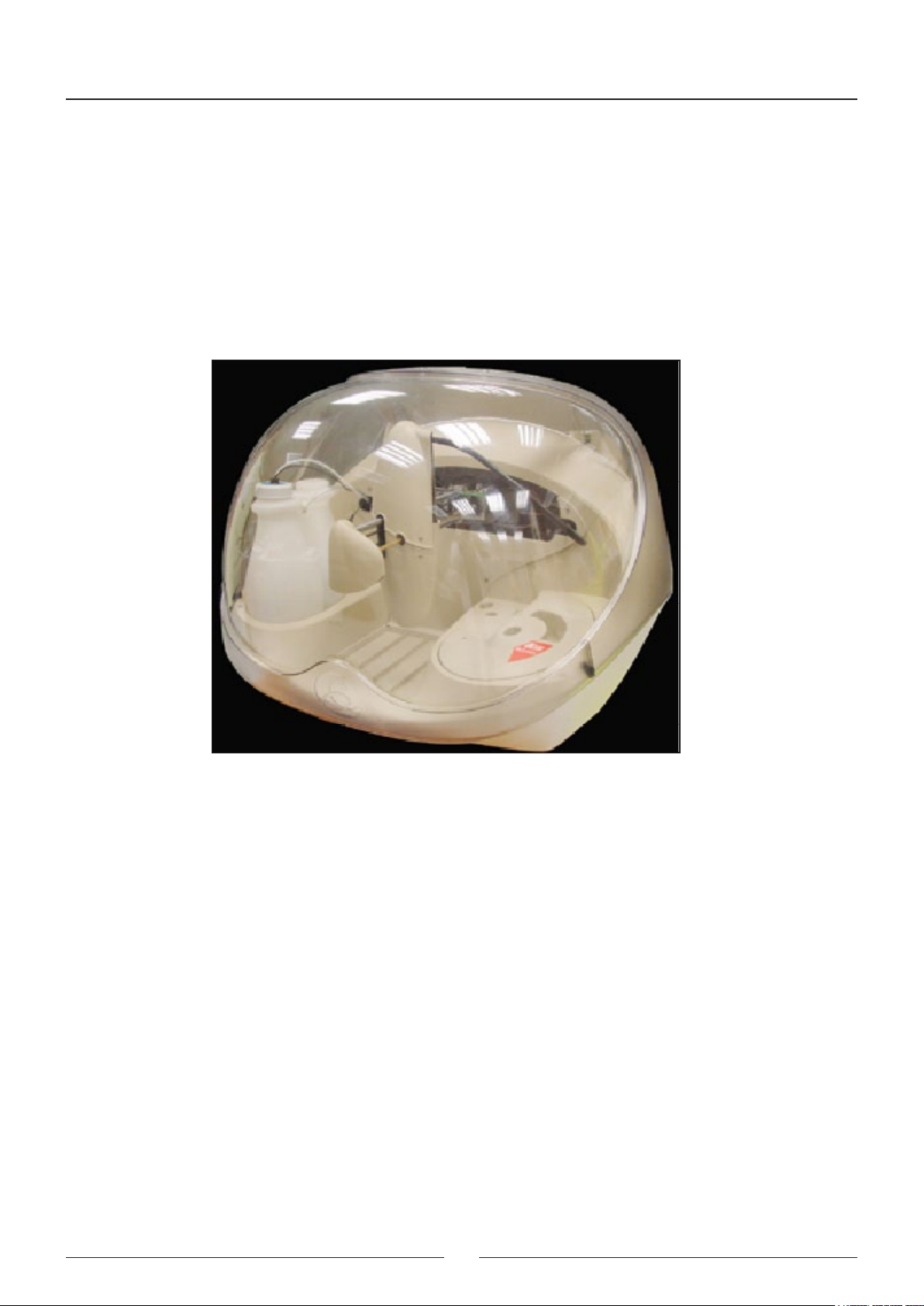
The A15 analyzer is an automatic random access analyser specially designed for performing biochemical and turbidimetric clinical analyses. The instrument is controlled on-line in real time from an external dedicated PC.
In each of the elements of the A15 analyser, BioSystems has used leading edge tech nology to obtain optimum analytical performance, as well as taking into account eco no my, robustness, easy use and maintenance. A three-axis
Cartesian operating arm prepares the reactions. Dispensing is performed by means of a pump with a ceramic piston
via a detachable thermostated needle. A washing station guarantees that the needle is kept perfectly clean throughout the process. The reactions take place in a thermostated rotor in which absorbance readings are taken directly by
means of an integrated optical system.
This manual contains the information required for learning about, maintaining and repairing the A15 automatic analyzer. It should be used by the Technical Service as a learning and consultation docu ment for the maintenance and
repair of the instru ment. Chapter 2 describes the different mechanical elements that form the analyzer together with
their functionality, and chapter 3 describes the electronic system. Chapter 4 describes the Service Program. All the
adjustments and checks of the analy zer are carried out through this program, which is independent from the appli cation
program (User Program). The separation of both programs enable it to be maintai ned separately and the extensions
and improvements of one do not affect the other. The user does not have the service program. The Technical Service
must install it on the user’s computer in order to carry out the service requirements. Once said tasks have been carried out, the Technical Service must uninstall the program. Chapter 5 offers instructions for the different mainte nance,
rep air and cleaning operations that can be carried out by the Technical Service. The annexes contain a summary of
the technical specications of the analyzer, the adjustment margin tables, the lists of accessories and spares, a list
of software versions and their compatibility and a software troubleshooting guide.
1.1. GENERAL DESCRIPTION OF THE ANALYZER
The A15 analyser is made up of three basic elements: the operating arm, the dispensing system and the reading and
reactions rotor. The electronic system of the instrument controls said elements and communicates with the external
computer containing the application program. Through this program, the user can control all the operations of the
analyzer.
8
1.1.1. Operating arm
This is a three-axis XYZ Cartesian mechanism. The X and Y axes move the dis pens ing needle over the analyser
horizontally and the Z axis moves it vertically. It is operated by three step-by-step motors. In each 24-second prepara-
tion cycle, the operating arm performs the following actions: rst of all, it sucks in the reagent from the corresponding
bottle. Next, the needle is washed externally in the washing station and sucks in the sample from the corresponding
tube. It is washed externally again and dispenses the sample and the reagent into the reactions rotor. Finally, it is
exhaustively washed internally and externally before proceeding with the next preparation. The arm has a system
for controlling vertical movement to detect whether or not the needle has collided into anything on descending. If a
collision occurs, as may be the case if, for example, a lid has been left on a bottle of reagent, the arm automatically
restarts, veries the straightness of the needle and continues working issuing the corresponding alert to the user.
A vertical axis retention system prevents the needle from falling in the case of a power cut, avoiding injury from the
needle to the user or the needle being bent by an attempt to move the arm manually. The operating arm only makes
the preparations if the general cover of the analyser is closed. If the cover is raised while it is functioning, the arm
automati cally aborts the task in progress and returns to its parked position to avoid injury to the user.
1.1.2. Dispensing system
This system consists of a thermostated needle, supported and displaced by an operating arm and conne ct ed to a
dispensing pump. The needle is detachable to enable cleaning and replacement. The analyser has capacity level
detection to control the level of the bottles and tubes and prevent the needle from penetrating too far into the corresponding liquids, thus minimising contamination. An automatic adjustment system informs the user if the needle is not
mounted or if it is too bent. The needle has a sophisticated Peltier thermos tatation system, with PID control, capable
of thermostating the preparations at approximately 37º in less than 15 seconds. Dispensing is carried out by means
of a low maintenance ceramic piston pump driven by a step-by-step motor. It is capable of dispensing between 3 and
1250 ml. The exterior of the needle is kept cons tantly clean by a wash station included in the base. A membrane pump
transports the waste to the corresponding container.
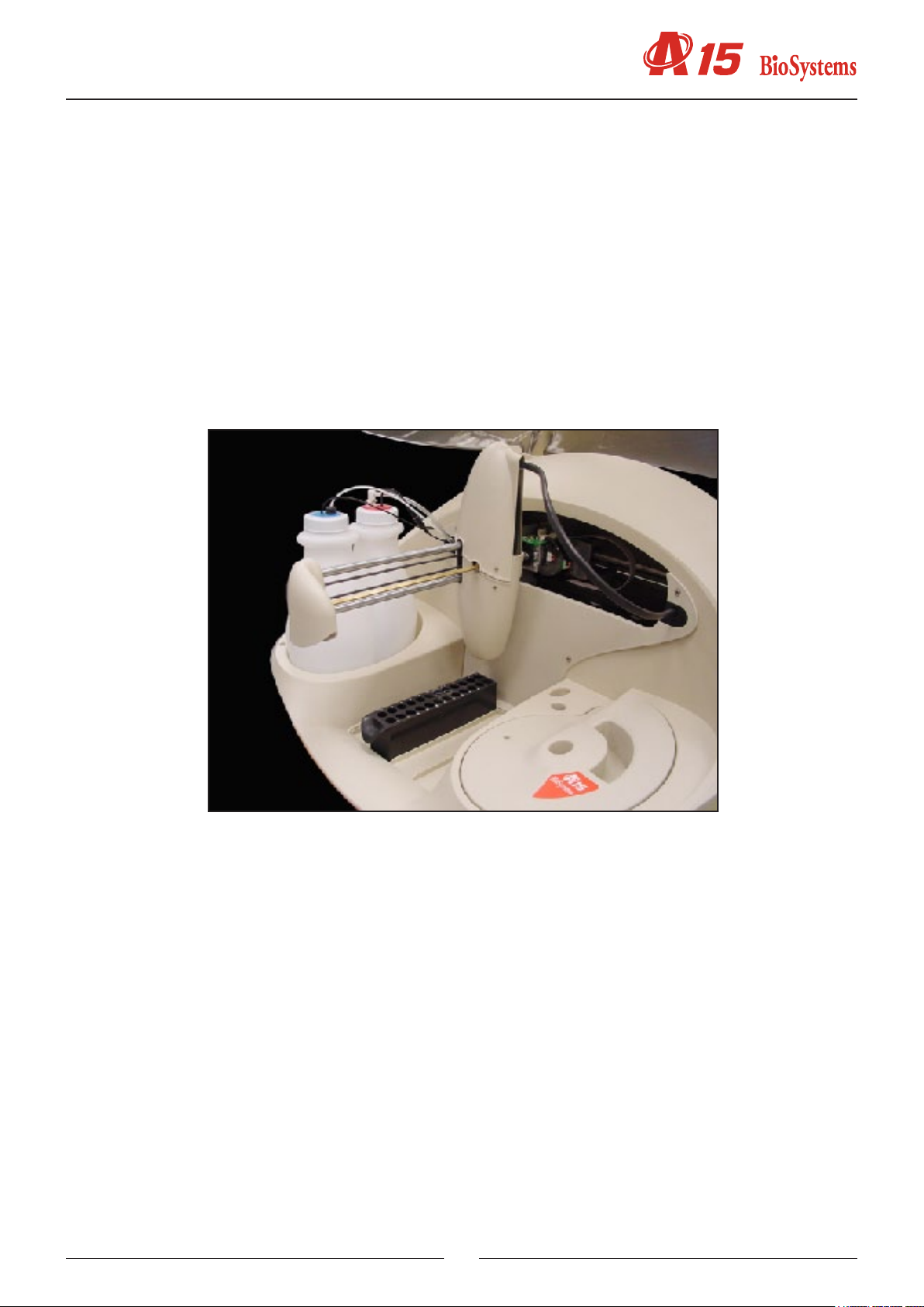
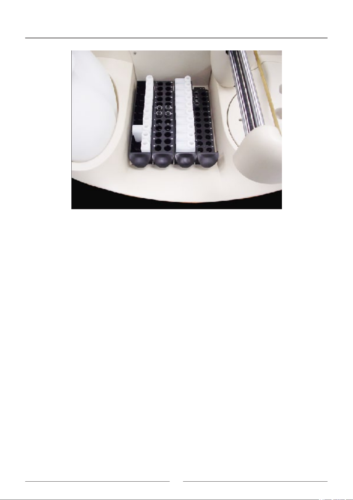
The A15 analyser has a tray with 4 free positions for racks of reag e nts or samples. Each reagents rack can carry up
to 10 reagents in 20 ml or 50 ml bottles. Each samples rack can contain up to 24 tubes of samples. The samples can
be patients, calibrators or controls. The analyser can be congured to work with 13 mm or 15 mm diameter tubes of
samples with a length of up to 100 mm or with paediatric wells. Any possible conguration of racks can be mounted
from 1 rack of reagents (10 reagents) and 3 racks of samples (72 samples) to 3 racks of reagents (30 reagents) and
1 rack of samples (24 samples).
On the left of the analyser are the waste and distilled water containers. The analyser constantly controls the level of
these containers and issues the appropriate alerts if the distilled water is nearly empty or if the waste container is full.
9
Service manual
1.1.3. Reactions rotor and reading
The preparations are dispensed in an optical quality methacrylate reactions rotor thermos tated at 37ºC. The optical
absorbance readings are taken directly on this rotor. Each reaction can be read for 10 minutes. The readings are
taken as they are programmed in each measurement procedure. The reaction wells have been designed to enable
the mixture of the sample and the reagent during the dispensing. Each rotor has 120 reaction wells. The length of the
light path is 6 mm. The minimum volume required to take the optical reading is 200 uL. The wells have a maximum
useful capacity of 800 uL. When the reactions rotor is completely full, the user must change it for one that is empty,
clean and dry. The reactions rotors can be reused up to 5 times if they are carefully cleaned immediately after use.
The Cleaning the semi-disposable reactions rotor section in the Installation and maintenance manual describes how
to cle an the rotors. The us er has a test in the computer programme, which he or she may use to check the condition
of the rotor. The rotor is driv en by a step-by-step motor with a transmission. A Peltier system with PID control thermostates the rotor at 37ºC.
An optical system integrated in the rotor takes the readings directly on the reaction wells. The light source is a 10 W
halogen lamp. The detector is a silicon photodiode. The wavelength is selected by a drum with 9 positions available
for optic lters. The lters are easily ch an ged by the user from the exterior of the analyser, without the need for disassembling the lter drum. A step-by-step motor positions the drum. The optical system is capable of taking 1.25 readings
per second, with or without a lter change in between. The light beam from the lamp passes through a compensated
interferential lter to select the desired wavelength. It then passes through the rotor well and nally reaches the pho-
todiode, where the light signal is turned into an electric signal. A sophisticated analogical digital integrator-converter
system converts the electric signal into a digital value with which the analyser obtains the absorbance values. The
optical system continues to work when the general cover of the ana lyser is open, whereby the analyser can continue
to take readings while the user handles, for example, the sample tubes or the reagent bottles. The rotor cover must
be in place for the optical system to work correctly.
10

A detector tells the analyser of the presence of the cover. The analyser aborts the readi ngs if the user removes the
rotor cover while the optical system is taking photometric measurements. If the rotor is not covered, the analyser
informs the user so that he or she places the rotor cover when it sends samples to be analyzed.
1.1.4. Electronic system
The described elements are controlled by an electronic system based on a micropro cessor. The microprocessor has
two exter nal communication channels to connect the instrument to the computer containing the application pro gram.
The electronic system is made up of the following independent boards:
- Microprocessor board
- Photometric system board
- Needle conditioning board
- Fluid system interconnection board
- Arm interconnection board
- Rotor interconnection board
- Power supply board
1.1.5. Application program
The application program makes it possible to control all the operations of the analy zer. Fro m this program, the user
can monitor the state of the analyzer and the work session, program parameters, e.g. technique parameters, prepare
the work session, prepare results reports, congure different analyzer options, activate various test utilities, prepare
and maintain the instrument and carry out internal quality control processes. The purpose of this manual is not to
explain the fun ction ing of the user program. For detailed information to this re gard, please con sult the User Manual
included with the analyzer.
1.2. FUNCTIONING OF THE ANALYSER
The A15 analyser is an automatic random access analyser specially designed for performing biochemical and turbidimetric clinical analyses. The analyser performs patient-by-patient analyses and enables the continual introduction
of samples. The analyser is controlled from a dedicated PC that is permanently com muni cated to the instrument.
The programme, installed on the computer, keeps the user constantly informed of the status of the analyser and the
progress of the analyses. As results are obtained, the com pu ter shows them to the user immediately.
When a Work Session is begun, the ana ly ser proposes performing the blanks, calibra tors and controls programmed
11

Service manual
for the measurement procedures it is to carry out. The user may choose between performing the blanks and the
calibra tors or not. If they are not performed, the analyser uses the last available memorised data. The controls can
also be activated or not. During a session, while the analyser is working, the user can introduce new normal or urgent
samples to be analyzed. Each time a new sample is added, the analyser automa tical ly proposes the possible new
blanks, calibrators or controls to be performed. A work session can remain open for one or more days. When a session
is closed and another new session is opened (Reset Session), the analyser again proposes performing the blanks,
calibrators and controls. It is recommended that the session is reset each working day.
The analyser determines the concentrations of the analytes based on optical absorbance measurements. To measure
the concentration of a certain analyte in a sample, the analyser uses a pipette to take a specic volume of the sample
and the corresponding reagent, quickly thermostates them in the needle itself and dispenses them into the reactions
rotor. The very dispensing speed together with the geometry of the reaction well causes the mixture to be shaken and
the chemical reaction begins. In the bireagent modes, the reaction begins when the analyser later dispenses a second
reagent in the same reaction well. The reactions can be biochemical or turbidimetric. In both cases, the reaction or
the chain of reactions produced generate substances that attenuate certain wave len gths, either by absorption or by
dispersion. Comparing the light in ten sity of a certain wavelength that crosses a well when there is a reaction and when
there is not a reaction can determine the concentration of the corresponding analyte. This comparison is quantied
with the physical magnitude called absorbance. In some cases, the concentration is a direct function of the absorbance, and in other cases, it is a function of the variation of the absorbance over time, depending on the analysis mode.
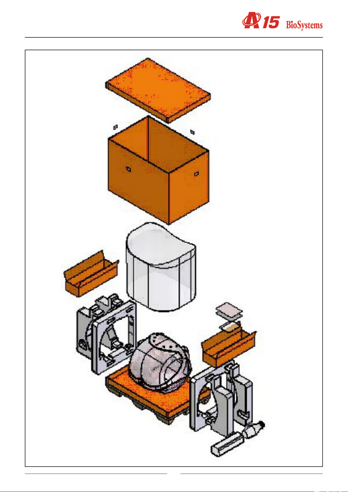
1.3. TRANSPORT AND RESHIPMENT OF THE ANALYZER
If the analyser is to be reshipped or moved using a transport vehicle, it is important to block the operating arm and
use the original packaging to ensure that the apparatus is not damaged. To package the instrument, we recommend
you follow the following instructions: (on the unpackaging instruc tions sheet)
12
13

Service manual
2. MECHANICAL ELEMENTS
2.1. Instrument breakdown
The physical structure of the analyzer can be broken down as follows:
-Operating arm
-X guide
-Y guide
-X carriage
-Y carriage
-Needle unit
-Dispensing system
-Thermostated probe
-Dispensing pump
-Tubes and containers
-Container level control sensors
-Racks tray with integrated washing station
-Waste pump
-Reactions rotor with integrated optical system
-Thermostated rotor and photometric system. This contains the electronic photo metric system board
-Lighting system
-Electronics box.This houses the electronic boards of the microprocessor, the power sup ply and the front indicator
-Main cover hinges
-Base
-Housings
-Upper casing
-Front housing
-Arm casing
-Main cover
The following is a brief description of each of the mechanical elements that make up the analyzer.
2.2. Description of the mechanical elements
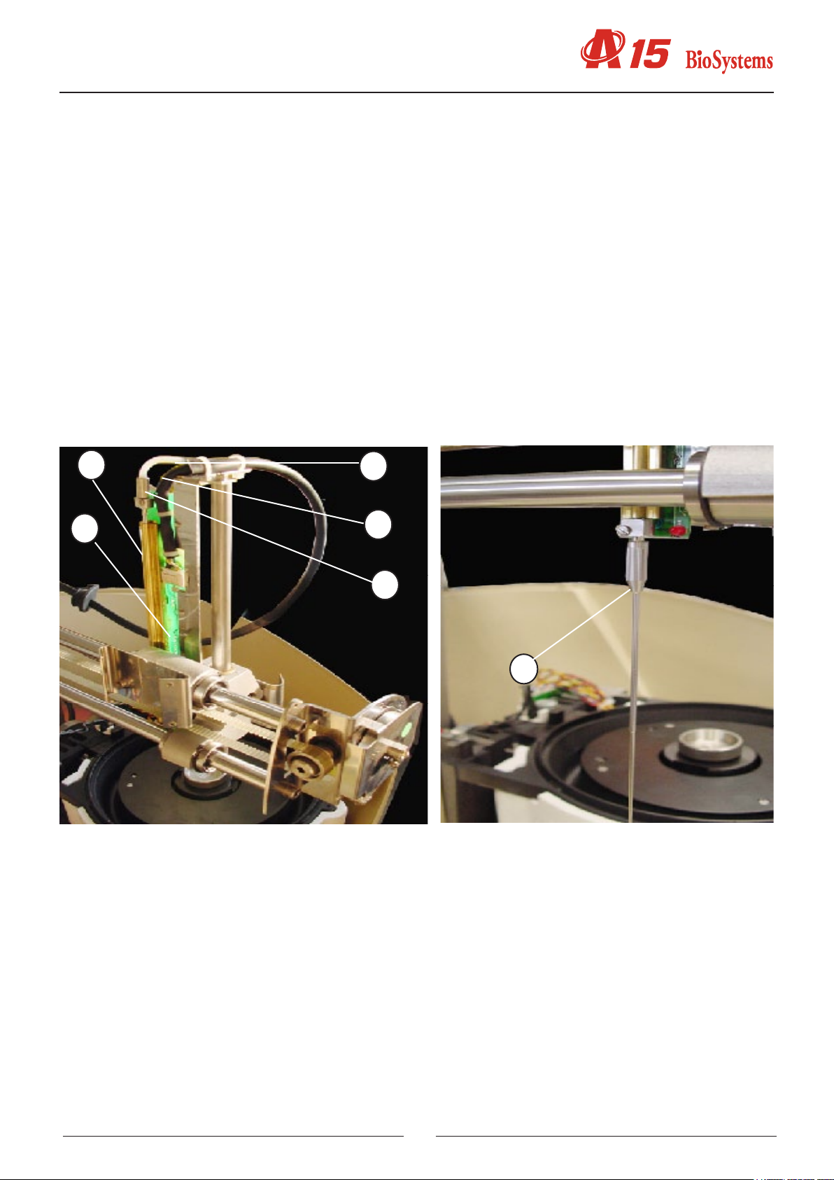
2.2.1. Operating arm
This mechanism positions the dis pen sing needle appropriately during the prepara tion of the analyses. An encoder
checks the vertical movement of the needle and a spring automatically stops it from falling in the case of a power cut.
The dispen sing pipe and the electrical hoses of the arm pass through the front casing
(1) X GUIDE
(2) X CARRIAGE
(3) Y CARRIAGE
(4) Y GUIDE
(5) NEEDLE UNIT
(6) CONTROL AND DISPENSING PIPE HOSE
The needle unit (5) supports the thermostated needle and can move on the Y carriage (3), which can move on the
Y axes (4). The Y axes are supported by the X carriage, which moves on the X axes (1). In this way, the needle can
be moved in the three Cartesian directions of X, Y and Z. The hose (6) houses the Teon dispensing tube and all the
electrical ho se s of the arm.
14
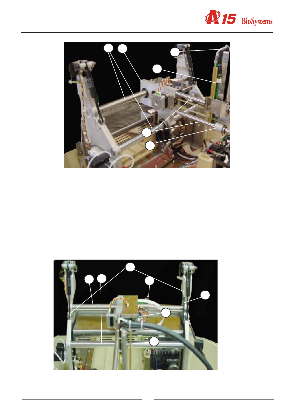
2.2.1.1. X Guide.
(1) UPPER X TOOTHED AXIS
(2) LOWER X AXIS
(3) X START PHOTOSENSOR
(4) BEARING X AXIS
(5) X MOTOR
(6) X START PHOTOSENSOR TAB
(7) AXIS SUPPORTS
1
2
6
5
4
3
This consists of two supports (7) that hold the steel axes (1 and 2) on which the X carriage moves. The photosensor
(3) indicates the start position of the X carriage movement. The motor X (5) is moved by a rack (2). The X carriage is
supported by the second axis (2) by means of a bearing (4).
7
2
1
3
6
5
4
15
Service manual
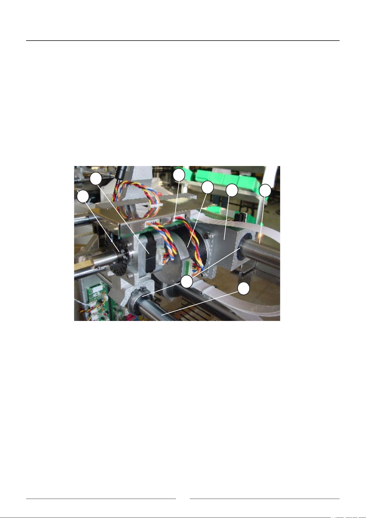
2.2.1.2. X Carriage
(1) X CARRIAGE BODY
(2) UPPER X AXIS - RACK
(3) LOWER X AXIS
(4) X MOTOR
(5) Z MOTOR
(6) ENCODER
(7) XYZ INTERCONNECTION PCB
(8) BEARINGS
The X carriage body (1) moves along the two axes (2, 3). The upper axis (2) acts as a rack. The X motor (4) is tted
with a pinion that moves the carriage. The X carriage also supports the interconnection PCB (7) and the Z motor (5).
To enable the movement, it uses linear bearings (8).
5
6
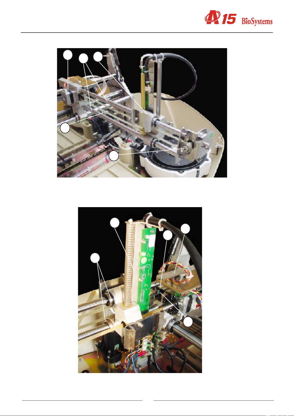
2.2.1.3. Y Carriage
(1) Y CARRIAGE BODY
(2) Y GUIDE AXES
(3) Y MOTOR
(4) BELT
(5) BELT RETURN PULLEY
(6) START PHOTOSENSOR
(7) START TAB
(8) NEEDLE UNIT
(9) BEARINGS
7
4
1
2
8
3
The body of the Y carriage (1) moves along the two axes (2) on linear bearings (9). The said axes are supported by
the X carriage. The movement is made by the Y motor (3) by the belt (4) and the return pulley (5). The start of the
movement is controlled by the tab (7) and the start photosensor (6) located on the X carriage (10). The body of the Y
carriage (1) also supports the needle unit.
16
3
1
2
4
5
8
10
7
9
6
17
Service manual
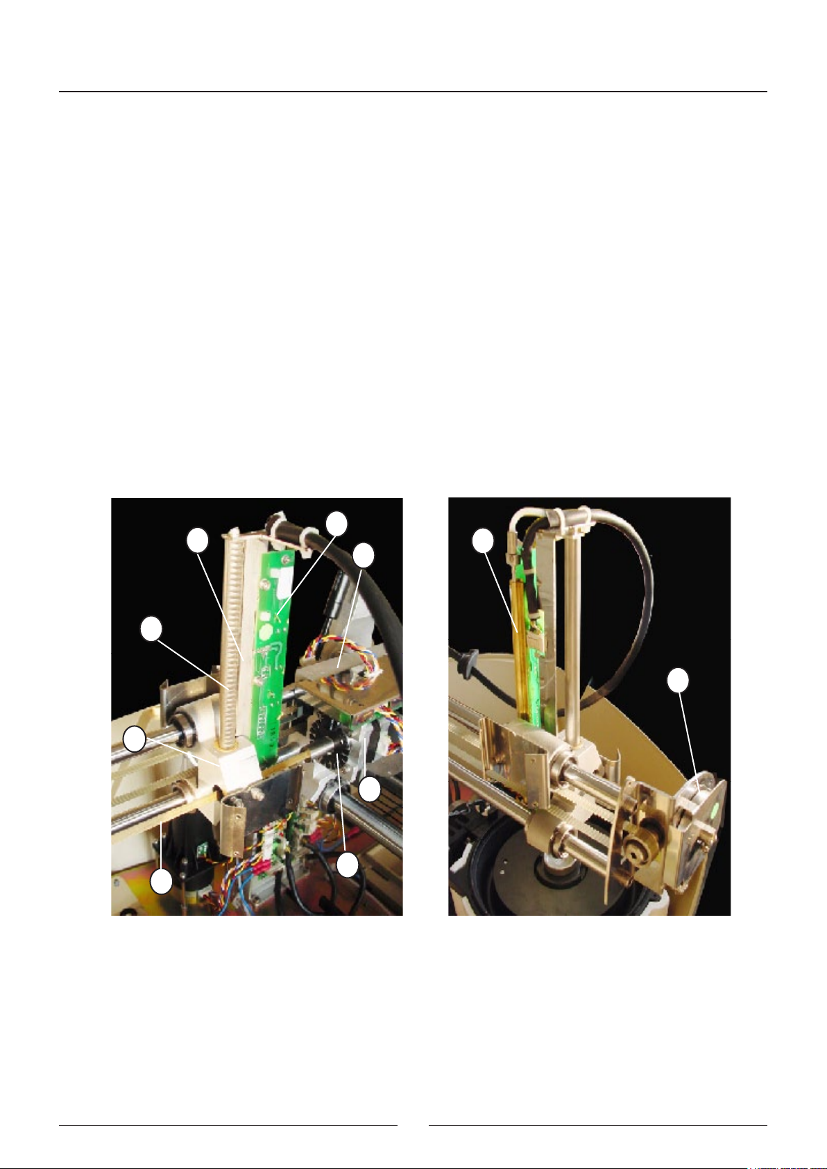
2.2.1.4. Needle unit
(1) Z GUIDE
(2) RACK
(3) Z MOTOR
(4) ENCODER
(5) TRANSMISSION AXIS
(6) RETURN SPRING
(7) THERMOSTATATION PIPE
(8) CONTROL PCB
(9) Y CARRIAGE
The Z guide (1) supports the thermostatation pipe (7) and the control PCB (8) where the heating elements are located,
together with the thermistor signal amplier and level detection and the Z axis start photosensor. The rack (2) supports
the Z guide (1) which crosses the Y carriage (9) on two bearings. The Z motor (3) is fastened to the X carriage (10)
and is moved by a transmission axis (5) tted with a pinion that acts on the rack. The return spring (6) acts on the
transmission axis and prevents the needle from falling in the event of a power cut: The encoder (4), which detects any
obstruction to the movement of the thermostated needle (9) is located on the same axis and on the part of the motor.
8
1
7
10
2
6
9
3
4
5
18
2.2.2. Dispensing system
The dispensing pump dispenses the preparations through the thermostated needle. The needle is washed internally
and exter nally at the washing station. The racks tray makes it possible to position the samples to be analyzed and
the required re a gents. The level of the distilled water and waste containers is controlled by the analyzer by capacity.
2.2.2.1. Thermostated probe
(1) THERMOSTATATION PIPE
(2) PCB
(3) TEFLON DISPENSING TUBE
(4) ELECTRICAL CONTROL HOSE
(5) FASTENING NUT
(6) REMOVABLE NEEDLE
The thermostatation pipe (1) preheats the reagent during dispensing. It is tted with two connectors at each end. The
removable needle (6) is connected to one and the Teon dispensing pipe (3) is connected to the other, xed by the
fastening connector (5). The PCB (2) contains the thermostatation elements, the thermistor and associated circuits.
The various thermistor and element action signals (3) pass through the hose (4).
1
2
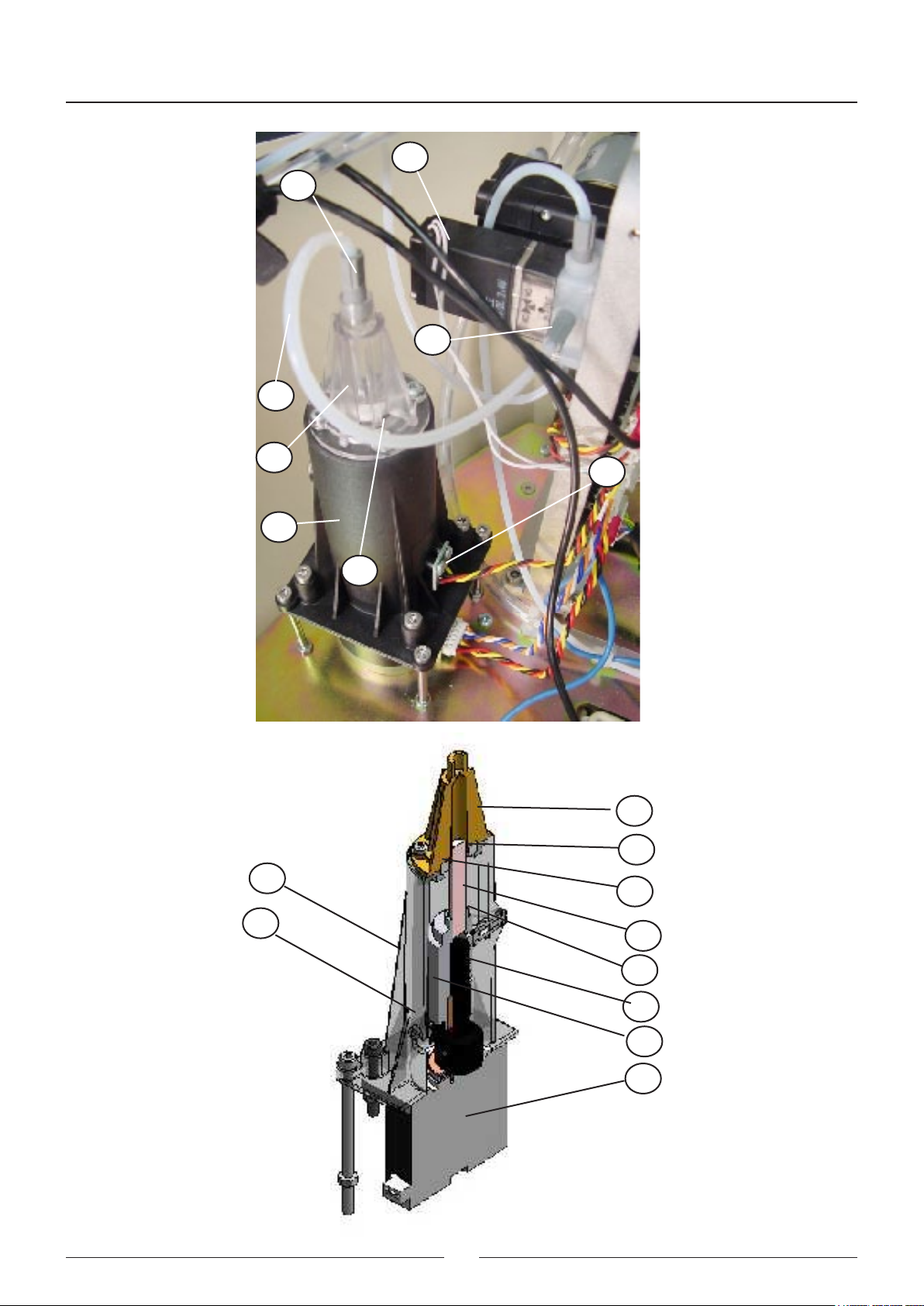
2.2.2.2. Dispensing pump
3
4
5
6
(1) BODY
(2) FLUIDIC CHAMBER
(3) SEAL
(4) SEAL SUPPORT
(5) CERAMIC PISTON
(6) PISTON SUPPORT
(7) START DETECTION BARRIER
(8) AXIAL BEARING
(9) ENDLESS SCREW
(10) MOTOR
(11) START PHOTOSENSOR
(12) PUMP NUT
(13) PUMP-ELECTROVALVE TEFLON TUBE
19
Service manual
14
12
15
13
2
11
1
3
2
3
1
4
7
5
6
8
20
9
10
(14) 3-CHANNEL ELECTROVALVE
(15) ELECTROVALVE NUT
The plastic body (1) joins the different elements that make up the pump. The transparent methacrylate uidic chamber
(2) makes it possible to observe the ow of liquid through the pump. The support (4) fastens the seal (3). The ceramic
piston (5) dispenses by displacing a certain volume of liquid in the chamber. The piston is adhered to the support (6),
which moves alternatively by the rotation of the endless screw (9) xed to the motor axle (10). The barrier (7), joined
to the piston support, obstructs the photosensor (11) when the piston reaches its start position. The axial bearing
(8) prevents any longitudinal displacement of the motor axle for greater precision in the dispensing operation. The
3-channel electrovalve (14) makes it possible to connect the pump chamber to the distilled water container or to the
thermostated needle. The Teon tube (13) connects the chamber to the electrovalve. It is connected to each of these
elements by the nuts (13) and (15).
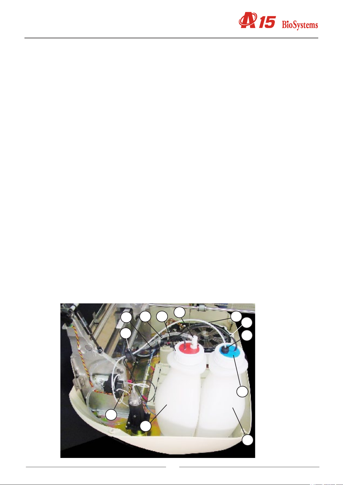
2.2.2.3. Tubes and containers
(1) WATER CONTAINER
(2) WATER CONTAINER LID
(3) WATER CONTAINER TUBES FASTENING
(4) WATER CONTAINER TEFLON TUBE
(5) TEFLON TUBE FILTER
(6) ELECTROVALVE NUT
(7) SYSTEM LIQUID LEVEL SENSOR CABLE
(8) LEVEL SENSOR
(9) WASTE CONTAINER
(10) WASTE CONTAINER LID
(11) FAST COUPLING NUT
(12) WASTE CONTAINER PVC TUBE
(13) GROMMET
(14) WASTE LEVEL SENSOR CABLE
The Teon tube (4) connects the distilled water container (1) to the electrovalve of the dispensing pump. This tube is
installed at the end of the lter container (5). It is connected to the electrovalve of the dispensing pump through the nut
(6) The Teon pipe passes through the rubber piece (3) in the lid (2) of the container, which fastens them in position.
The PVC tube (12) connects the waste extraction membrane pump to the waste container (9). The waste container
lid (19) has a fast coupling nut (11) with automatic drip-proof closing when disconnected. All the tubes pass into the
interior of the analyzer through the rubber grommet (13).
14
12
10
11
4
7
13
3
2
6
9
21
1
Service manual
5
8
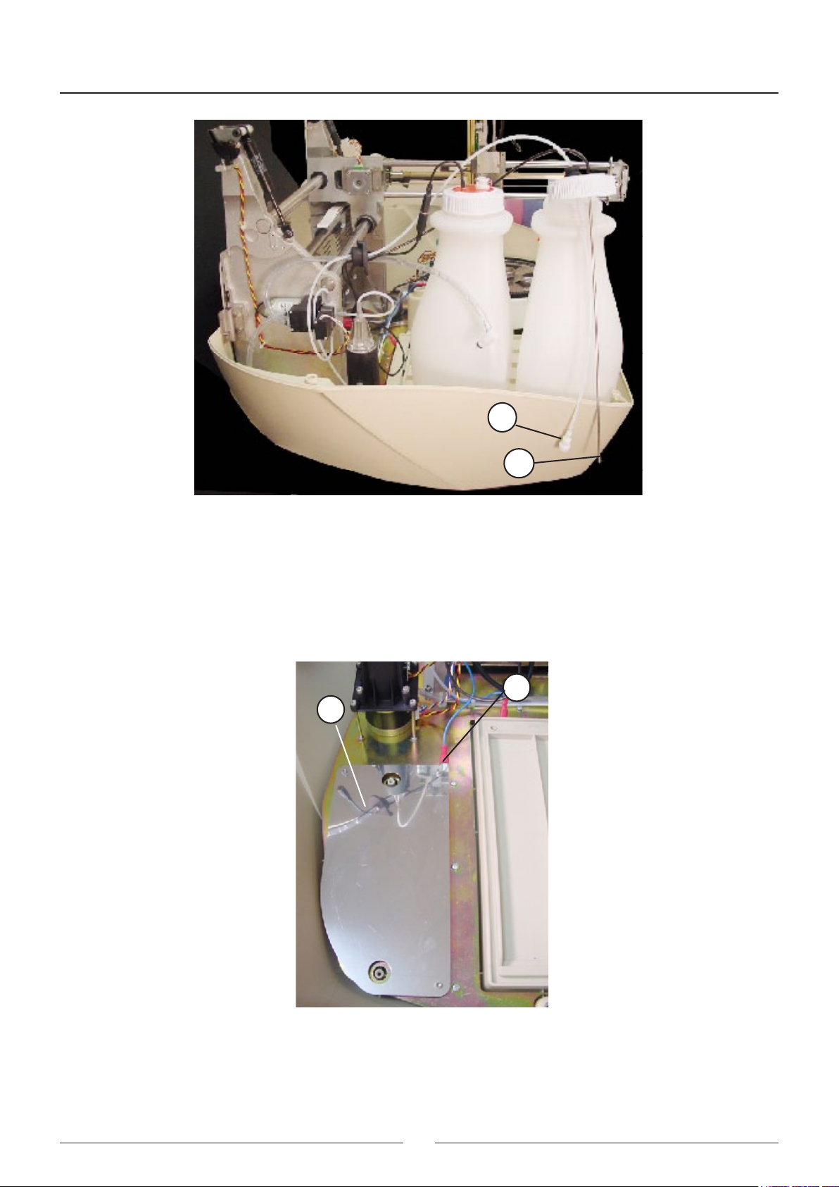
2.2.2.4. Container level control sensors.
(1) LEVEL DETECTION SHEETING
(2) SIGNAL CONNECTOR
The analyzer has a capacitance system to control the level of the distilled water and waste containers. For this, there
is an emission plane (1) under the bottles where a signal is injected through the connector (2). The base supporting
the bottles is above this. They have 2 rods that collect the signal and indicate the presence or absence of liquid.
2
1
22
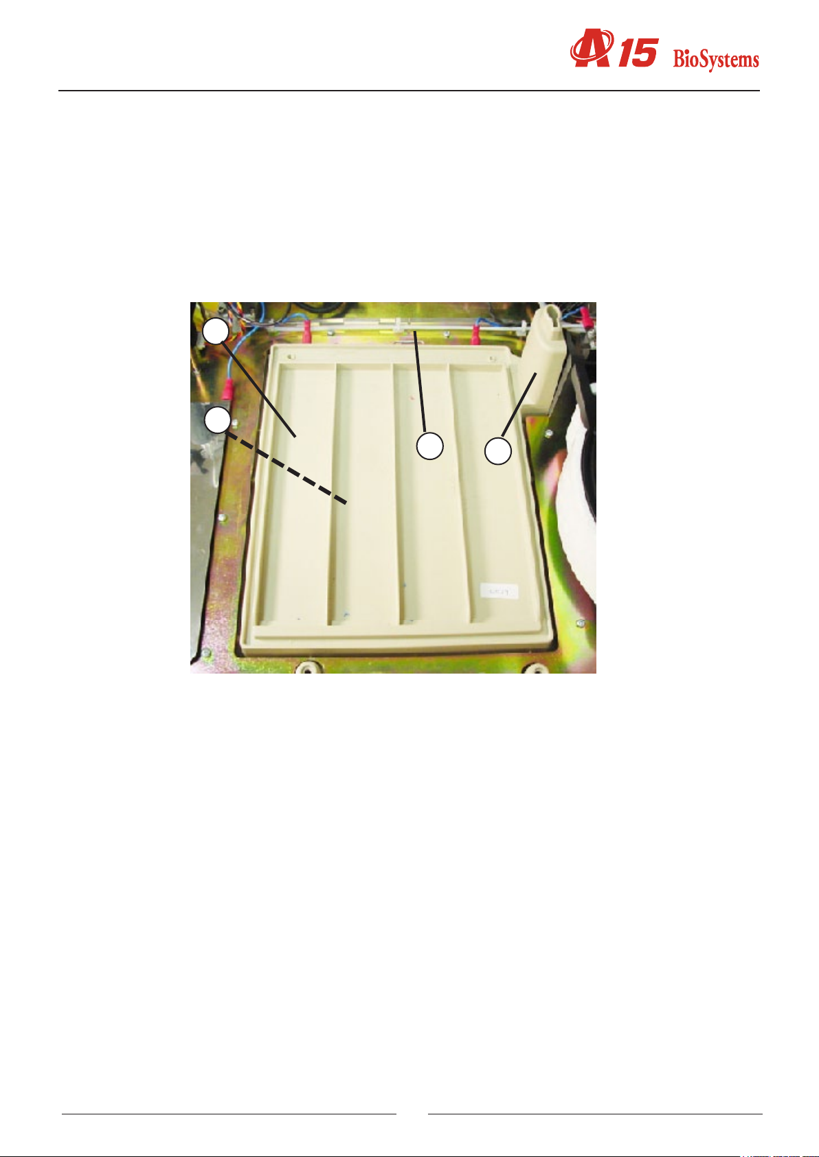
2.2.2.5. Racks tray with integrated washing station.
(1) TRAY
(2) WASHING STATION
(3) LEVEL DETECTION SHEETING
(4) WASTE PVC PIPE
The plastic injection tray (1) is part of the base of the instrument. The washing station (2) is installed on the right.
The plate (3) detects the level of the dispensing needle. The PVC tube (4) connects the washing station drain to the
waste extraction pump.
1
3
4
2
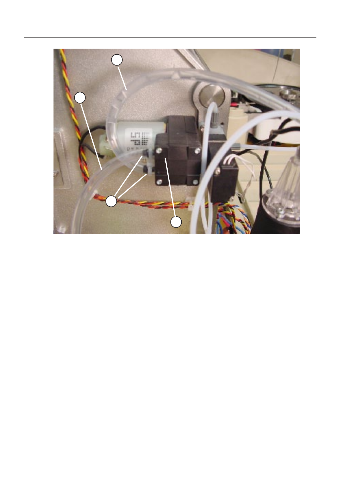
2.2.2.6. Washing pumps
(1) MEMBRANE WASTE PUMP
(2) WASHING STATION-PUMP PVC TUBE
(3) WASTE BOTTLE-PUMP PVC TUBE
(4) SAFETY FLANGES
The needle washing system has a waste extraction pump (1). This is connected to the washing station by the PVC (2).
The pump expels the waste through the pipe (4) into the waste bottle. The pipes are fastened by two safety anges.
23
Service manual
3
2
4
1
2.2.3. Reaction rotor with integrated optical system.
The reactions rotor is thermostated at 37ºC. The optical system, made up of a lighting system and a photometric
system takes the readings directly on the rotor reaction wells. The lighting system has a halogen lamp, a lter drum
for the selection of the wavelength form the appropriate beam of light. The photometric system contains a silicon photodiode and the corresponding electronics to obtain a digital value that is proportionate to the light intensity received.
2.2.3.1. Thermostated rotor and photometric system
(1) METHACRYLATE ROTOR
(2) HEATING CANAL
(3) THERMAL INSULATION OF THE HEATING CANAL
(4) PELTIER CELLS
(5) HEATSINKS
(6) FANS
(7) TEMPERATURE PROBE
(8) ROTOR CENTRING UNIT
(9) ROTOR FASTENING SCREW
(10) HOME ROTOR PHOTODETECTOR
(11) BEARINGS
(12) PINION
(13) ROTOR MOTOR
(14) ROTOR CROWN
(15) MOTOR SEPARATOR
(16) PHOTOMETRIC SYSTEM BOARD
(17) ELECTRONIC BOARD SUPPORT COVER
(18) OPTICS COVER
(19) PHOTODIODE GAP CENTRING UNIT
(20) ROTOR GAP
(21) COVER DETECTOR
(22) ROTOR AXLE
24
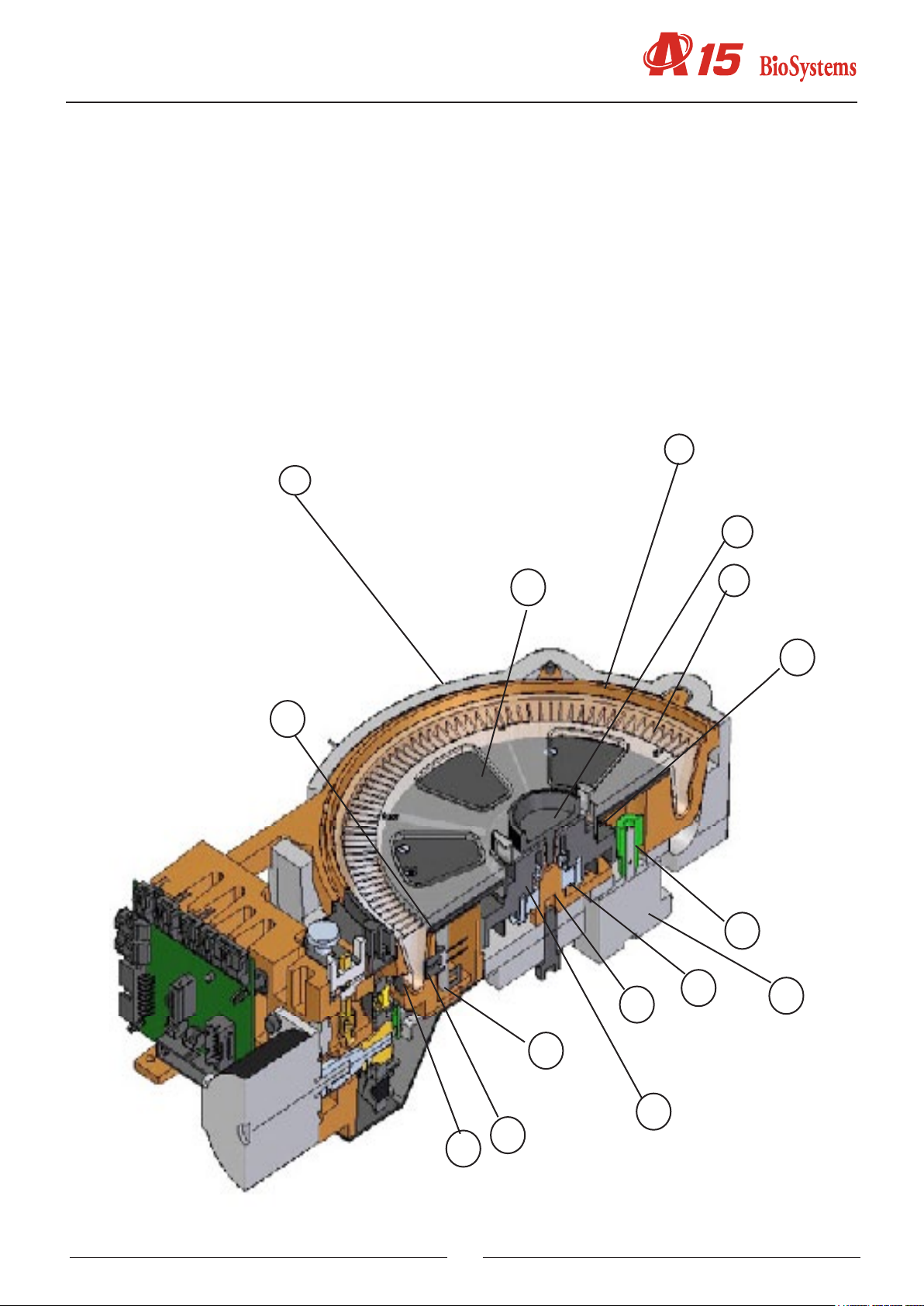
The dispensing system dispenses the reagents and the samples in the methacrylate rotor (1). The optical system
measures the absorbance directly on the rotor wells. The aluminium heating canal (2) surrounds the rotor and keeps
it at 37ºC. The canal is thermally insulated from the exterior by means of the moulded expanded polystyrene insulation (3). The Peltier cells (4), with their respective radiators (5) and fans, act on the canal to control the temperature.
The sensor used to control the temperature is the probe (7). The methacrylate rotor is fastened to its centring unit
(8) by means of the screw (9). The centring unit is xed to the heating canal through the axis (22), which is tted on
bearings (11). The barrier obstructing the photosensor (10) when the rotor reaches its start position forms part of
the centring unit (8). The centring unit also acts as gearing. The pinion (12), xed to the motor (13), acts through the
crown (14), which also acts as a centring unit. The separator (15) does not allow the motor temperature to reach
the heating canal. The electronic board of the photometric system (16) is housed in a cavity in the heating canal.
The upper cover of this cavity (17) supports the electronic board. The seal (18) keeps the cavity hermetically closed
in the case of possible liquid spillage. The housing of the lter drum is closed at the bottom by the cover (18). The
part (19) centres the photodiode with regard to the lighting system and also acts as a grill to prevent the incidence of
unwanted light. The grill (20) limits the light hitting the reactions rotor. The detector (21) tells the analyzer if the rotor
cover is in position or not.
2
3
9
17
17
22
11
1
14
7
13
20
25
16
8
19
Service manual
3
18
10
7
21
2.2.3.2. Lighting system
(1) BODY
(2) LAMP HOLDER
(3) HALOGEN LAMP
(4) LAMP HOLDER FASTENING
(5) FILTER WHEEL
(6) FILTER HOLDER
(7) FILTER HOLDER NUT
(8) MATCHED INTERFERENTIAL FILTERS
(9) WHEEL AXLE
(10) HOME PHOTODETECTOR
(11) FILTER MOTOR
(12) DIAPHRAGM
(13) FILTER WHEEL WINDOW COVER
(14) FILTER WHEEL
(15) GAP
6
5
4
13
15
26
The aluminium body (1) is the structure that supports all the elements of the lighting system. The lamp holder (2),
fastened to the body by means of the fastening system (4), keeps the halogen lamp (3) in position without the need
for adjustments. The lter drum (5) has 10 positions for optical lters. Position 0 must always be taken up by a covered lter. The other positions can be taken up by an interferential lter (8) or by other covered lters. No position in
the drum must be left unoccupied. Each lter is tted on a lter holder (6) and fastened to it by the nut (7). The lter
holders can be dismounted from the drum by simply pulling on them. The cover (13) allows easy access to the lter
drum. The lter drum is fastened to the axle (9). This axle can be turned by the direct action of the motor (11). Its end
is guided by the bearing (14). The photosensor (10) indicates the start position of the drum. The light from the lamp,
limited by the diaphragm (12). The light passes through the lter drum, which selects the desired wavelength, and
through the aperture(15), which adapt the form of the light beam to the geometry of the rotor wells.
1
13
14
15
4
2
8
3
7
6
12
5
9
11
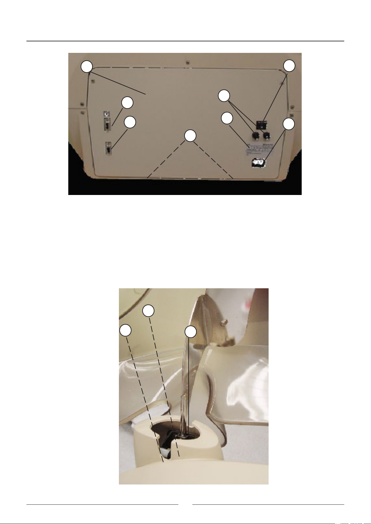
2.2.4. Electronics cover
(1) BACK COVER OF THE ELECTRONICS
(2) MAINS SWITCH
(3) FUSE HOLDER
(4) ID LABEL
(5) NETWORK CONNECTOR
(6) COM1 CONNECTOR
(7) COM2 CONNECTOR
(8) HINGES
The metal cover (1) supports the mains switch (2) and the fuse holders (3), as well as the identication label (4). The
COM1 and COM2 connectors (6, 7) and the mains connector (5) are fastened to the electronics box. The cover(1)
opens on 2 hinges (7).
27
Service manual
1
6
7
8
2.2.5. Main cover hinges
(1) HYDRO-PNEUMATIC SPRING
(2) ARTICULATED STEEL STRUCTURE
(3) COVER OPEN PHOTOSENSOR (on right-hand hinge only)
2
3
4
5
The two hinges enabling the raising of the main cover of the analyzer consist of an articulated steel structure (2)
operated by a hydro-pneumatic spring (1). The right-hand hinge includes a photosensor (3) to detect whether or not
the cover of the analyzer is open or closed.
1
3
2
28
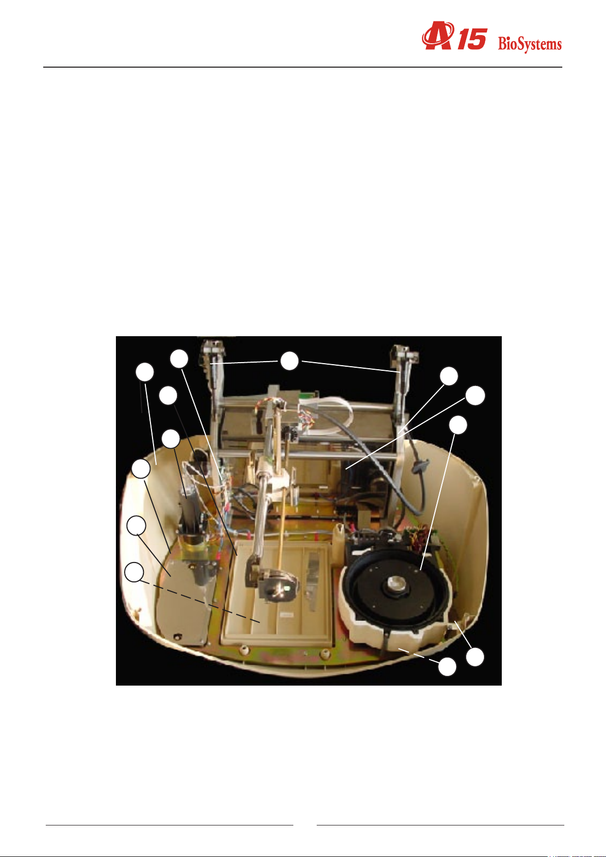
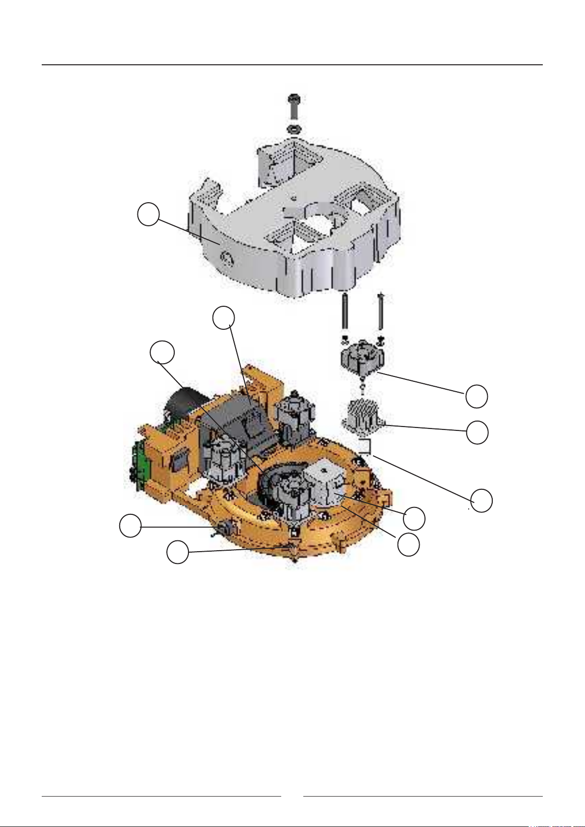
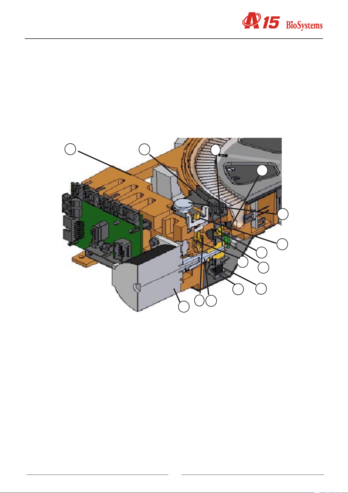
2.2.6. Base
(1) LOWER PLASTIC CASING
(2) BASE
(3) WASHING STATION AND RACK TRAY
(4) ARM UNIT
(5) ELECTRONICS BOX
(6) DISPENSING PUMP
(7) REACTION ROTOR AND INTEGRATED OPTICAL SYSTEM
(8) BOTTLE LEVEL DETECTION PLATE
(9) LEVEL DETECTION PLATE
(10) PUMP AND MICROPROCESSOR INTERCONNECTION BOARD
(11) MAIN COVER HINGES
(12) FRONT INDICATOR
(13) ADJUSTABLE LEG
The base (2) on which all the elements of the analyser are xed is fastened directly to the lower plastic casing. The
rack tray and washing station form part of the base. The instrument stands on 4 rubber legs . The front right leg (13)
is adjustable in height to adapt the instrument to the work surface.
10
1
3
11
4
5
7
6
2
8
13
9
29
12
13
Service manual
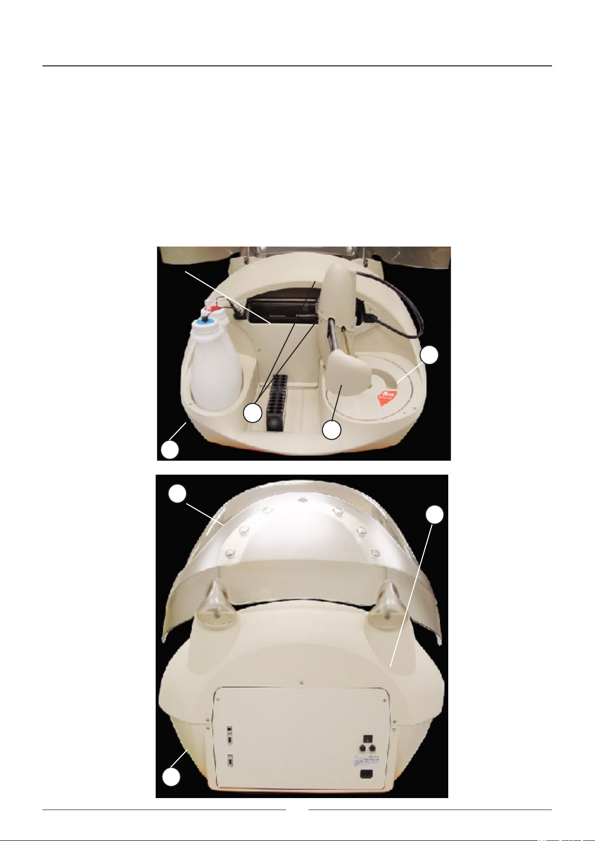
2.2.7. Casings
(1) FRONT CASING
(2) UPPER CASING
(3) MAIN COVER
(4) LOWER CASING
(5) ARM HOUSING
(6) ROTOR COVER
(7) RETURN SPRING COVER
The front casing (1) is fastened to the upper casing (2) and the upper casing is fastened to the lower casing (4). The
top cover (3) is transparent and lets users see the analyser in operation with the cover closed.
6
5
7
4
3
2
4
30

3. ELECTRONIC SYSTEM
1. Description of the electronics of the A15 analyzer.
2. CPU Board (CIIM00026)
3. Power supply board and source (SP150 & CIIM00015)
4. Needle Board (CIIM00017)
5. Photometry Board (CIIM00027)
6. XYZ carriage interconnection board (CIIM00018)
7. Rotor interconnection board (CIIM00029)
8. Fluid interconnection board (CIIM00028)
9. Communications Board (CIIM00036)
10. Components relation
11. Information about auxiliar connector
12. Interconnection between boards
13. Schematic liquid circuit
Description of the electronics of the A15 analyzer.
The electronics of the analyzer are made up of different boards located at different points in the analyzer and dedica-
ted to specic functions. Its different location corresponds to functionality and performance criteria for the functioning
of the analyzer.
There are 8 different boards, which correspond to:
CPU Board (CIIM00026)
Power supply board and source (SP150 & CIIM00015)
Needle Board (CIIM00017)
Photometry Board (CIIM00027)
XYZ carriage interconnection board (CIIM00018)
Rotor interconnection board (CIIM00029)
Fluid interconnection board (CIIM00028)
Communications Board (CIIM00036)
3.1 CPU Board (CIIM00026)
This is the brain of the machine, containing the microprocessor (H8/3003), responsible for controlling all the elements
of the machine. The board has different data storage systems using either static RAM (U1 and U47), FLASH memory
(U10) or EPROM (U9). The slot associated with the EPROM is used to check the functionality of the board and the
recording of the MONITOR program in the production phases of the analyzer. The other two memories are associated
with the normal functioning of the analyzer. The FLASH memory holds the application itself as well as different databases related to factory settings, adjustments, state of the rotor and possible extensions to the application.
The U21 device also exists on the board. This is a logical programmable device (FPGA) dedicated to the control of
motors, mapped in register memory associated with end-of-run control, electrovalves, level sensing and control of the
photometry-associated board (CIIM00027).
The motor control acts directly on the drivers corresponding to each of the analyzer’s axes (U28,U29,U30,U24,U25,U27)
to act on the motor. The driver comprises the L6228 integrated circuit. The regulation of the current of each axis can
be congured by means of a DAC that sets the current set point independently (U26).
The action on the thermostatation systems of the rotor is carried out through H-shaped bridges based on MOS technology (U45) and controlled directly from the microprocessor. The action on the needle thermostatation system is
through the Q4 transistor.
31

Service manual
Connector Function Pins
J1 Not available
J2 Connection to communications board
(CIIM00036)
J4 Connection to XYZ interconnection
board (home and encoder signals)
J5 Connection to XYZ interconnection
board (motor signals)
1 - V DC
2 - GND
3 - Tx0
4 - GND
5 - Rx0
6 - GND
7 - GND
8 - Tx1
9 - GND
10 - Rx1
1 - V DC
2 - GND
3 - Needle encoder
4 - Home motor Y
5 - Home motor X
6 - GND
1 - coil 2 motor X
2 - coil 2 motor X
3 - coil 1 motor Y
4 - coil 1 motor X
5 - coil 1 motor Y
6 - coil 1 motor X
7 - coil 2 motor Y
8 - coil 2 motor Z
9 - coil 2 motor Y
10 - coil 2 motor Z
11 - coil 1 motor Z
12 - coil 1 motor Z
J6 Connection to interconnection
board
Rotor (home motor signals and
photometry board control signals)
1 - 12 V
2 - GND
3 - DVALID
4 - DCLK
5 - DOUT
6 - DXMIT
7 - RANGE2
8 - RANGE1
9 - RANGE0
10 - TEST
11 - CONV
12 - GND
13 - CLKAD
14 - GND
15 - GND
16 - V DC
17 - V DC
18 - Rotor cover
19 - GND
20 - Rotor thermistor
21 - Home motor lter drum
22 - GND
23 - Home motor rotor
24 - Front red LED
25 - Front green LED
32

Connector Function Pins
J7 Connection to rotor intercon-
nection board (motor and
Peltier signals)
J8 Connection to interconnec-
tion board uids (electrically
operated valve and pump
signals)
J9 Connection to interconnec-
tion board uids (ceramic
pump home and level sensor
signals)
1 - coil 2 motor lters
2 - coil 2 motor lters
3 - coil 1 motor lters
4 - coil 1 rotor motor
5 - coil 1 motor lters
6 - coil 1 rotor motor
7 - Peltier
8 - coil 2 rotor motor
9 - Peltier
10 - coil 2 rotor motor
11 - V(24 V)
12 - Peltier fans
1 - V(24 V)
2 - Waste pump
3 - V(24 V)
4 - Electrically operated valve
5 - coil 1 ceramic pump
6 - coil 1 ceramic pump
7 - coil 2 ceramic pump
8 - coil 2 ceramic pump
1 - Waste bottle sensor input
2 - System liquid sensor input
3 - Bottle detection signal
4 - Rack level detection signal
5 - Ceramic pump home
6 - V DC
7 - GND
8 - Instrument cover detection
J10 Connection to needle board 1 - V (12 V)
2 - GND
3 - Home motor Z
4 - Needle thermistor
5 - Rack level detection signal
6 - V (24 V)
7 - Needle thermostat elements
8 - NC
J11 Connection to supply board 1 - V (12 V)
2 - GND
3 - V (24 V)
4 - V DC
5 - Fan control
6 - Lamp control
33

Service manual
Analogical circuitry:
The waste and system liquid sensors function through U6, U5 and U4, which generate and detect the signal responsible
for detecting the waste and system liquid. These signals are sent and received through the uid interconnection board
(connected to the CPU board by J9). The rack level detection is carried out in a similar way through U7, U8 and U2.
The signal injected to the base of the bottles goes to the uid interconnection board through J9 and is collected after it
has been amplied by J10 (connection with the needle board). There is also a circuit for conditioning the signal of the
thermistor associated with the thermostatation of the rotor that is made up of the U1 and U2 circuits. The thermistor
is connected to the rotor interconnection board, which is connected to the CPU board.
TP1 - Waste pump control signal
TP2 - Electrovalve control signal
TP3 - Rotor thermistor signal
TP4 - RESET
TP5 - WATCHDOG
TP6 - LSO_BOT bottle detection signal
TP7 - Bottle signal
TP8 - Needle detection signal
TP9 - LSO needle detection signal
TP10 - Attenuated LSO needle detection signal
TP11 - IN1 Needle Peltier Driver
TP12 - Needle resistance driver
TP19 - ASL
TP20 - HWR_L
TP21 - LWR_L
TP22 - WE_L
TP24 - CS_FPGA_L
TP25 - DVALID (photometry)
TP26 - 12 Volts analogical
TP27 - IN2 Needle Peltier Driver
TP28 - EF Needle Peltier Driver
TP30 - DOUT (photometry)
TP33 - RANGE (photometry)
TP34 - CLKAD (photometry)
TP35 - Conditioned thermistor signal
TP38 - DXMIT (photometry)
TP39 - Analogical GND
TP40 - Power GND
TP41 - Power GND
TP42 - Power GND
TP43 - Digital GND
TP44 - Digital GND
TP45 - Digital GND
LIST OF LED DIODES
DL1 - Electrovalve driver
DL2 - Waste pump driver
DL3 - PELTIER heating
DL8 - PELTIER cooling
DL4 - Needle resistance driver
34

35

Service manual
3.2 Power Supply Board (CIIM00015)
This is made up of 2 different switched regulators and 1 voltage line that enable distribution of the power supply in
accordance with the requirement of each subsystem.
Connector Function Pins
J1 24 V input 1 - 24V
3 - (GND)
J2 Output voltage of 6 V for lamp
supply
J3 Output voltage of 24 V, 12V,
5 V and fan and lamp control
input
J4, J5 Fan output voltage of 24 V 1 - 24V
TP1 - Lamp voltage from 5.75 V <6V
TP2 - 12V analogicals
TP3 - 5V digital
1 - 12 V
3 - GND
1 - 36V
2 - GND
3 - 12V
4 - 5V
5 - ENABLE LAMP
6 - ENABLE FAN
2 - GND
List of LED diodes:
D4 - Indicates 5V activated
D2 - Indicates 12V lamp activated
D3 - Indicates 12V analogicals activated
36

37

Service manual
3.3 Needle Board (CIIM00017)
This board conditions the thermistor signal associated with the thermostatation of the needle, the preamplication of
the level detection signal and the Z home. It receives, from the needle unit, the thermostatation elements, the thermistor and the level signal detected by the needle itself.
The cables that join this board with the CIIM00026-01 board come from this needle.
Connector Function Pins
J1 CPU board connection
(CIIM0026)
TP1 - Needle signal
TP2 - Output preamplier needle signal
TP3 - Output amplier thermistor signal
TP4 - Thermistor
12V - 12V voltage
5V - Voltage 5V
AGND - GND
1 - GND POWER
2 - 12V analogical
3 - level sensor
4 - Home Z
5 - GND POWER
6 - Thermistor
7 - EARTH
8 - GND POWER
9,10 - Thermo elements.
38

39

Service manual
3.4 Photometry Board (CIIM00027)
This board also has the heart of the absorbance measuring system for the samples to be analyzed. It is made up of
a photosensor and an associated analogical-digital conversion circuitry (DDC112).
Connector Function Pins
J3 Photometric board connection CIIM00029) 1 - 12 V
2 - GND
3 - DVALID
4 - DCLK
5 - DOUT
6 - DXMIT
7 - RANGE2
8 - RANGE1
9 - RANGE0
10 - TEST
11 - CONV
12 - GND
13 - CLKAD
14 - GND
15 - GND
16 - V DC
JP1 - soldering bridge - Solder only if the local oscillator and the U4 and U5 scales, respectively, are not present.
JP2 - soldering bridge - as per JP1
JP3 - soldering bridge - joins together the analogical and digital frames
40

3.5 XYZ Interconnection Board (CIIM00018)
This board interconnects the CP1 board with the X carriage. It distributes the X and Y motor signals and transmits the
home signals of the X and Y movements. It also sends the encoder signal to the CPU board.
Connector Function Pins
J1 Connection motor X
J2 Connection motor Y
J3 Connection motor Z
J4 C P U b o a r d c o n n e c t i o n
(CIIM00026)
J5 C P U b o a r d c o n n e c t i o n
(CIIM00026)
1 - coil 2 motor Y
2 - V DC
3 - coil 2 motor Y
4 - GND
5 - coil 1 motor Y
6 - encoder
7 - coil 1 motor Y
8 - home motor X
9 - coil 2 motor Y
10 - home motor X
11 - coil 2 motor Z
12 - GND
1 - coil 2 motor X
2 - coil 2 motor X
3 - coil 1 motor X
4 - coil 2 motor Z
5 - coil 2 motor Z
6 - coil 1 motor Z
41

Service manual
3.6 Communications Board (CIIM00036)
This enables communication with the exterior of the analyzer through a USB channel or a RS232 channel. It also
includes an auxiliary RS232 channel for monitoring the functions of the analyzer during its execution.
Connector Function Pins
J1 CPU board connection (CIIM00026) 1 - V DC
2 - GND
3 - Tx0
4 - GND
5 - Rx0
6 - GND
7 - GND
8 - Tx1
9 - GND
10 - Rx1
CN1 - USB Connector
P1 - Main RS232 connector
P2 - Auxiliary RS232 connector
42

3.7 Rotor interconnection board (CIIM00029)
This interconnects the rotor with the CPU board.
Connector Function Pins
J1 Rotor motor connection
J2 Power connection with board CIIM00026 1 - Coil 2 rotor motor
2 - Coil 2 rotor motor
3 - Coil 1 rotor motor
4 - Coil 1 motor lters
5 - Coil 1 rotor motor
6 - Coil 1 motor lters
7 - Peltier
8 - Coil 2 motor lters
9 - Peltier
10 - Coil 2 motor lters
11 - V24 (fans)
12 - GND (fans)
J3 Connection with photometry board CIlM00027 1 - 12 V
2 - GND
3 - DVALID
4 - DCLK
5 - DOUT
6 - DXMIT
7 - RANGE2
8 - RANGE1
9 - RANGE0
10 - TEST
11 - CONV
12 - GND
13 - CLKAD
14 - GND
15 -GND
16 - V DC
J4 Connection motor lters 1 - Coil 1
2 - Coil 1
1 - Coil 2
2 - Coil 2
J5 Peltier connection 1 - Peltier black
2 - Peltier, red
J6 Fan connection 1 - Fan, black
2 - Fan, red
J7 Connection signal with board CIM00026 1 - 12 V
2 - GND
3 - DVALID
4 - DCLK
5 - DOUT
6 - DXMIT
7 - RANGE2
8 - RANGE1
9 - RANGE0
10 - TEST
11 - CONV
12 - GND
13 - CLKAD
14 - GND
15 - GND
16 - V DC
17 - V DC
18 - Rotor cover sensor
19 - GND
20 - Thermistor signal
21 - Home lter drum
22 - GND thermistor
23 - Home rotor
24 - Front LED (red)
25 - Front LED (green)
26 - Ambient sensor
43

Service manual
Connector Function Pins
J8 Rotor cover sensor connection 1 - Cable 1
2 - Cable 2
J9 Thermistor connection 1 - Cable 1
2 - Cable 2
J10 Front LED connection
J11 Connection Home motor lters
J12 Connection Home rotor
J13 Connection fans 1 - Fan, black
1 - Front LED, red
2 - Front LED, black
3 - Front LED, green
1 - Photo sensor, yellow
2 - Photo sensor, black
3 - Photo sensor, red
1 - Photo sensor, yellow
2 - Photo sensor, black
3 - Photo sensor, red
2 - Fan, red
List of LED diodes
DL1 Peltier
DL2 Home rotor motor
DL3 Home lter motor
DL4 Rotor cover
44

3.9 Pump interconnection board (CIIM00028)
The pump interconnection board interconnects the CPU board with the dispensing pump, the waste pump,
the electrovalve, the bottle level sensor and the instrument cover.
List of LED diodes
Connector Function Pins
J1 Waste sensor 1 - Waste sensor
J2 Connection signal with board CIIM00026 1 - Waste sensor
2 - System liquid sensor
3 - LS/waste signal
4 - Needle liquid detection signal
5 - Home dispensation pump
6 - V DC
7 - GND
8 - Instrument cover
J3 System liquid sensor 1 - System liquid sensor
J4 LS/waste sensor signal 1 - System liquid signal
J5 Needle liquid detection signal 1 - Needle liquid detection signal
J6 Dispensation pump home 1 - Photo sensor, yellow
2 - Photo sensor, black
3 - Photo sensor, black
J7 Electrovalve 1 - White cable
2 - White cable
J8 Power connection with board CIIM00026 1 - 24 V electrovalve
2 - GND
3 - Waste pump
4 - Waste pump
5 - Dispensation pump coil 1
6 - Dispensation pump coil 1
7 - Dispensation pump coil 2
8 - Dispensation pump coil 2
J9 Waste pump 1 - Waste pump, red
2 - Waste pump, black
J10 Waste pump 1 - Coil 1
2 - Coil 1
4 - Coil 2
5 - Coil 2
J11 Instrument cover 1 - Photo sensor, yellow
2 - Photo sensor, black
3 - Photo sensor, red
DL1 Electrovalve
DL2 Waste pump
DL3 Home pump
DL4 Instrument cover
45

Service manual
46

3.10 Component relation
Component Reference
Home detector TCST1300
3 way electrovalve LVM115-6A-2U-1 from SMC
Cover magnet Neodimio D4x5
Lamp 6V 10W Gilway L6402
Pump motor NMB23ML-C343V-1
Rotor motor NMB17PMKD18V
Washing system motor SP600-EC-LC-L
Filter wheel motor NMB23ML-C343V-1
X motor NMB23ML-C343V-1
Y motor NMB17PMKD18V
Z motor NMB17PMKD18V
Rotor peltier TES-06339
Probe temperature sensor B57861-S302-F40
Rotor temperature sensor B57861-S302-F40
Hall efect sensor RELE REED A041 1D 2H 0500
Electronic box fan SUNON KD2406PTS1
Rotor fan SUNON KD2404PKS2
3.11 Auxiliar channel information
The rear left part of the instrument is where the communications cables are connected. There are two connections,
the COM1 and the COM2.
The COM1 is the main connection from the analyser to the computer. This connection should be always present to
analyser run propertly.
there are two connection types:
A - Cable type USB
B - Cable type RS-232
Only connect one cable type.
47

Service manual
The labeled connector COM2 is the auxiliar connector.
This connector is used to communicate with a second serial port in the computer. The function of this cable is to monitor the internal states of the analyser.
To show all this information, the user should execute the program: windows HyperTerminal and congure with the
following parameters:
Programa: Inicio\Todos los programas\accesorios\comunicaciones\hyperterminal
Baud Rate: 38400
Número de bits: 8
Stop bits: 1
Paridad: none
Onces is congured and connected the cable, switch on the analyser. In this moment will appear in the HyperTerminal
screen information about the analysers mode and the different executes states. In the initializate mode, the analyser
do an internal checking for each element, if someone has any error then in the screen will show the element that fails.
The following lines shows an exemple of the instructions during an initialization, (this information could change with
the improvements of the rmware) :
BIOSYSTEMS A15
Firmware initialization
Firmware Version: A15 User V3.12
Serial Number: 831050311
FLASH functions transferred to RAM
Interrupt Vectors transferred to RAM
Interrupts enabled
Checking rmware integrity
Checking program checksum:
Checksum correct! Program Checksum=0x5039 Size=427100
Checking A15 conguration checksum:
Checksum correct! Conguration Checksum=0x179C Size=856
Checking A15 conguration backup checksum:
Checksum correct! Conguration backup Checksum=0x179C
Size=856
Loading A15 Conguration from FLASH
Conguration in FLASH is correct
Adjustments loaded:
Temperature correction for Rotor=0.50
Temperature correction for Probe=0.00
System Liquid Detection=30
Waste Detection=29
Sensitivity of level detection=110
Origin X=60
Origin Y=280
Origin Z=430
Tray Reference X=675
Tray Reference Y=10
Washing station X=360
Washing station Y=5
Washing station Z=450
Washing station Ext X=360
Washing station Ext Y=95
Washing station Ext Z=540
Reactions Rotor X=110
Reactions Rotor Y=1044
Reactions Rotor Z=600
Rotor Distance between the dispensation point and the optic
system=610
Rotor Position correction regard to the dispensation point=98
Rotor Position correction regard to the optic system=-4
Filters Wheel correction=0
Filters and their Integration Times:
Filter 1=000 Integration Time= 20ms ( 40) Reference Time=
0ms ( 0)
Filter 2=340 Integration Time=205ms (400) Reference Time=
0ms ( 0)
Filter 3=405 Integration Time= 51ms (100) Reference Time=
0ms ( 0)
Filter 4=505 Integration Time= 51ms (100) Reference Time=
0ms ( 0)
Filter 5=535 Integration Time= 51ms (100) Reference Time=
0ms ( 0)
Filter 6=560 Integration Time= 51ms (100) Reference Time=
0ms ( 0)
Filter 7=600 Integration Time= 51ms (100) Reference Time=
0ms ( 0)
Filter 8=635 Integration Time= 51ms (100) Reference Time=
0ms ( 0)
Filter 9=670 Integration Time= 51ms (100) Reference Time=
0ms ( 0)
Filter 10=000 Integration Time= 20ms ( 40) Reference Time=
0ms ( 0)
TI/LB Hystoric:
F[01]: 00000000 00000000 00000000 00000000 00000000 00000000
00000000 00000000 00000000 00000000
F[02]: 00000000 00000000 00000000 00000000 00000000 00000000
00000000 00000000 00000000 00000000
F[03]: 00000000 00000000 00000000 00000000 00000000 00000000
00000000 00000000 00000000 00000000
F[04]: 00000000 00000000 00000000 00000000 00000000 00000000
00000000 00000000 00000000 00000000
F[05]: 00000000 00000000 00000000 00000000 00000000 00000000
00000000 00000000 00000000 00000000
F[06]: 00000000 00000000 00000000 00000000 00000000 00000000
00000000 00000000 00000000 00000000
F[07]: 00000000 00000000 00000000 00000000 00000000 00000000
00000000 00000000 00000000 00000000
F[08]: 00000000 00000000 00000000 00000000 00000000 00000000
00000000 00000000 00000000 00000000
F[09]: 00000000 00000000 00000000 00000000 00000000 00000000
00000000 00000000 00000000 00000000
F[10]: 00000000 00000000 00000000 00000000 00000000 00000000
00000000 00000000 00000000 00000000
F[01]: 000 000 000 000 000 000 000 000 000 000
F[02]: 000 000 000 000 000 000 000 000 000 000
F[03]: 000 000 000 000 000 000 000 000 000 000
F[04]: 000 000 000 000 000 000 000 000 000 000
F[05]: 000 000 000 000 000 000 000 000 000 000
F[06]: 000 000 000 000 000 000 000 000 000 000
48

F[07]: 000 000 000 000 000 000 000 000 000 000
F[08]: 000 000 000 000 000 000 000 000 000 000
F[09]: 000 000 000 000 000 000 000 000 000 000
F[10]: 000 000 000 000 000 000 000 000 000 000
Zmax Reference=1130
- Pediatric Offset=0
- 13mm Offset=0
- 15mm Offset=0
- Reagent Offset=0
- Central Reagent Offset=0
A15 Mechanical History
- X axis: 0 Steps
- Y axis: 0 Steps
- Z axis: 0 Steps
- Rotor: 0 Steps
- Filter Wheel: 0 Steps
- Ceramic Pump: 0 Steps
- Washing Station Pump: 0 Cycles
- Washing Station Valve: 0 Cycles
- Ceramic Pump Valve: 0 Cycles
- Lamp: 0 Minutes
A15 Statistics
- Biochemistry Tests: 0
- Turbidimetry Tests: 0
- Biochemistry Bireagent Tests: 0
- Turbidimetry Bireagent Tests: 0
- Predilutions: 0
- Initial/Final Washings: 0
- Washing Solution Washings: 0
- System Liquid Washings: 0
- New Rotor: 0
- Bireagent Contaminations Solved: 0
9: Start Rotor Readings
Notes: Use only in Service Mode
after a Base Line Test.“
Rotor Read
1: Choose Filter +
2: Choose Filter User Mode Test
G: Test
Notes: Use only after a Worklist in
Stand By.“
This tests dumps all the preparations“
parameters received and the photometric“
readings. Finally performs a general test“
of the analizer.“
After this test press New Rotor
for continue working.“
DDC112/Photometry
D: Choose Mode
- DDC112 internal test mode
- DDC112 Photometry Mode
- Stop
+: Integration Time +0.5ms
-: Integration Time -0.5ms
Notes: Only works in Service Mode
This tests performs continuous“
readings with the DDC112.“
Remember stop the test for “
continue working.“
Caution: Dont’t abuse of this functions while the
analizer is running.“
<>
Rx
Stand by mode!
LC
TxS
Rx
Inicio modo servicio!
Setting racks layout
Tray Ref. X=675 => Distance from tray reference to tray corner X=2190
Tray Ref. Y=10 => Distance from tray reference to tray corner Y=30
Absolute position of tray corner X=2865
Absolute position of tray corner Y=-20
Generating Zmax Map:Ok
“
CPU settings: MDCR=c4;ABWCR=0;ASTCR=ff“
BioSystems A15“
Hello World“
A15 MAGIC KEYS“
H: Help“
R: Rotor Temperature“
P: Probe Temperature
S: Level Scales
A: Last A15 Stress Results
L: Actual Sensitivity of Level Detection
N: Enable Level Detection Debug
K: Power Supply On
Buzzer Control
B: Buzzer On
b: Buzzer Off
Encoder
E: Generate Encoder Error
I: Enable Encoder IRQ
Rotor Reading
1: Choose Filter +
2: Choose Filter -
Hardware Initialization
Programming FPGA XC2S50PQ208
- Clearing FPGA program memory: OK!
- Programing FPGA: OK
FPGA XCS50PQ208 is programmed
Initialization of level detection system
- Generating Sensitivity Map:Ok
Level Detection Mode:Normal
Pediatrico:
Rack 1 2 3 4
173 141 129 126 123 125 129 151
161 129 118 115 113 115 125 141
158 128 114 111 108 111 121 138
156 127 113 108 107 110 118 139
156 127 112 108 107 110 117 145
155 126 112 108 106 110 121 146
161 128 113 110 106 112 121 151
160 132 112 111 106 113 121 151
167 133 115 112 108 114 124 156
171 136 117 116 113 119 129 163
177 145 123 122 116 124 136 172
202 160 139 135 133 138 155 190
Tubo 13/15mm:
Rack 1 2 3 4
162 141 126 123 119 123 132 147
149 132 115 115 111 115 121 137
145 126 110 111 107 112 115 136
148 127 111 108 106 110 117 136
148 127 112 111 105 110 118 144
49

Service manual
149 128 111 111 107 113 119 145
154 126 113 110 108 111 119 144
155 128 115 111 110 113 124 145
161 130 114 112 110 115 125 148
161 133 117 112 112 116 125 154
169 140 123 121 118 122 133 161
190 155 134 133 128 134 146 176
Reactivos:
Rack 1 2 3 4
163 151 152 183
156 141 143 174
152 138 140 173
150 134 137 172
154 135 138 176
156 139 143 181
160 138 145 187
166 145 149 194
173 150 156 204
194 172 173 228
Initializating Motors
- Axis Z in HOME
- Axis Y in HOME
- Axis X in HOME
- ROTOR in HOME
- FILTERS WHEEL in HOME
- CERAMIC PUMP in HOME
Motors Initializated
Optics Initialization
- Filter correction=0
- Rotor correction=98 Rotor Lect. correction=-4
- Used wells:0
L: Actual Sensibility of Level Detection
N: Activate additional information of level detection (only
internal use)
K: Deactivate the power supply
B: Activate the buzzer
b: Deactivate the buzzer
E: Generate an encoder error (only internal use)
I: Activate the encoder interrupt (only internal use)
1: Increase the lter wheel position
2: Decrease the lter wheel position
9: Mesure the whole rotor, step by step
G: Once nish a work list, push the G and send to the
hyperteminal more detailed information of the work list
managemnet
D: Show the mesure depending on the number of key
pressed
1st press: activate the internal test DDC112,
always show the same count number
2nd press: activate the normal mesure DDC112,
show the count number mesured
3th press: stop the DDC112 mesure
+: Increase the integration time in 0.5ms
-: Decrease the intergration tie in 0.5ms
- Check DDC112..OK (FPGA 8Mhz Clock: OFF)
- DDC112 test: OK! (Result => 0046387)
Optics Initializated
Generating Pattern: 1 1 1 1 1 1 1 1 1 1 1 0 0 0 0 0 0 0 0 0
Generating Gate: 0 0 0 0 1 1 1 1 0 0 0 0 0 0 0 1 1 0 0 0
OK
Z Axis Initialization
- Axis Z in HOME
Z Axis initializated
Penc:111111111000000000| OK
Z Axis Initialization
- Axis Z in HOME
Z Axis initializated
Probe AA
- X:X=Xcal+-1“
- Y:Y=Ycal+0“
AAEnd
Peltier Cells and Drivers Test
- Probe Peltier Driver Test: Ok! (Not implemented)
- Rotor Peltiers Driver Test: Ok!
Hardware Initializated
There are a few keys that work with the Hyperterminal,
to press some keys the analyser give information about
some element, the following keys has the function:
H: Help, help, shows the help text
R: Rotor Temperature, shows the rotor temperature
P: Probe Temperature, shows the needle temperatare
S: Level Scales, shows the scales mesures in %
A: Last A25 Stress Results
50

3.12 Interconnection between boards
The following diagrams show the connections between the boards and the different elements that make up the analyzer.
51

Service manual
52

53

Service manual
54

55

Service manual
56

3.13 Schematic liquid circuit
57

Service manual
4. SERVICE PROGRAM
The service program is used for the adjustment, checking and maintenance of the different components of the
analyzer. It is not supplied with the instrument, it is supplied to authorised technical services only. The personal
of the Technical Service must install it on the user’s computer in order to carry out the service requirements.
Once the tasks have nalised, the program must be uninstalled. To install the program, follow the instructions
on the installation CD ROM called Service. The original password for using this program is A15. The password
can be changed from the service program itself. If the service personnel forget the password, the original password can be reinstalled by deleting the hidden le code.A15 from the application directory and relaunching
the program. Once the password has been introduced, the analyzer serial number is given and the name of
the operator is requested (by default Operator1). Press the Accept button and the main program appears. The
different functions of the service program are classied in the following categories:
- Adjustments: These make it possible to make different parameter adjustments required for the correct
functioning of the analyzer.
- Tests: Tests for checking the functionality of the a na ly zer.
- Utilities: Different technical utilities, such as, for example, washing or priming the dispensing sys tem
or changing an optical lter.
- Registers:This enables the management of past adjustments, tests, incidences, repairs and maintenance
of the instrument.
- Monitor:These enable the low level communication with the analyzer to load new versions of the program
in the ash memory of the analyzer (rmware) or to consult the internal parameters of the instrument.
An emergency stop button (STOP on a red background) will be accessible at all times, and when pressed, it
switches off the analyzer and closes the application quickly.
4.1 Initialising the analyser
To initialise the analyser in service mode, rst launch the A15 Service application. The program rst of all requests a user or technician ID to be used in the program. Depending on the type of user identied, access to
the different parts of the program will be allowed or denied. The following screen appears:
For full access, enter the following codes:
Name (login): SAT
Password: A15
58

Once the user has been identied correctly, the service program starts to initialise the analyser.
This screen appears when the analyser has nished the previous operations done to enter the SERVICE mode. If
the complete hardware of the analyzer is in correct conditions, the result “Hardware initiated correctly» displays.
If any hardware element presents an operational problem, it will appear “Hardware not initiated completely” in
the screen, and the element that is not working correctly will be shown.
In order to close the screen and continue working, you should press the Accept button.
In order to get a printed copy of this initialization report, you should press the Print button.
NOTE: If an error has been reported and the technician continues working with the service program, he must
consider that there is a hardware element that is not working properly.
59

Service manual
4.2. ADJUSTMENTS
These make it possible to make different parameter adjustments required for the correct functioning of the
analyzer. All the values to be adjusted have certain limited ranges, indicated by the service program. These
values are also given in an appendix at the back of this manual. If, after varying any of the parameters within
its permitted range, the analyzer is not tuned up, it indicates that the corresponding system is broken and in
need of repair.
4.2.1. Adjustment of the needle thermostatation system
This screen adjusts the needle thermostatation in such a way that the dispensing temperature of the reactions
60

is as close as possible to 37ºC. To make this adjustment, the analyzer must be initialised. The liquid to be dispensed is taken from the system liquid container or from the bottle of reagent selected by the technician. The
technician must measure the temperature of the dispensed liquid with a thermometer calibrated at 37ºC. The
program shows the control set point temperature, which is the parameter that must be adjusted for the dispensing temperature to be correct. This parameter must be different from 37ºC. When the technician so indicates,
the analyzer dispenses thermostated distilled water on a certain position in the racks tray shown on the screen.
The technician must measure the temperature of the water with the calibrated thermometer and introduce the
temperature on the screen. The analyzer automatically modies the set point temperature in accord with the
temperature measured with the thermometer for the dispensing temperature to be 37ºC. The technician can
modify this set point temperature proposed by the program. On pressing Adjust, the analyzer thermostates
the needle with the new set point and, when the technician so requests, performs new dispensing operations.
Each time the set point temperature is modied, wait 1 minute before performing new dispensing operations
for the needle temperature to become stabilised. The technician must repeat this process until the dispensing
temperature is as near as possible to 37ºC. Pressing the Store button, the analyzer stores the current value
of the adjusted set point temperature. Pressing the Cancel button keeps the last stored value and the current
value is not stored. Pressing the Restore button restores the initial screen input value.
4.2.2. Adjustment of the rotor thermostation system
This screen makes it possible to adjust the thermostation system of the rotor in such a way that the reactions
temperature is 37ºC. To make this adjustment, place a well rotor in position and ensure that the analyzer has
been initialised. The rotor can be automatically lled with distilled water by pressing the corresponding button.
Once lled, the technician must wait a few minutes for the rotor to be thermostated. The temperature in the
rotor wells must be measured with a temperature calibrated at 37ºC through the dispensing hole of the rotor
cover. A button makes it possible to turn the rotor in increases of 15 wells to change the well on which the
measurement is being taken. The program shows the control set point temperature, which is the parameter that
must be adjusted for the temperature of the rotor to be correct. This parameter must be other than 37ºC. The
technician must measure the temperature of the water with the calibrated thermometer in the wells and enter
the temperature on the screen. The analyzer automatically modies the set point temperature in accord with
the temperature measured with the thermometer for the rotor reactions temperature to be 37ºC. The technician
can modify this set point temperature proposed by the program. On pressing Adjust, the analyzer thermostates
the rotor with the new set point. Each time the set point temperature is modied, wait 5 minutes before performing new dispensing operations for the rotor temperature to become stabilised. The technician must repeat
this process until the rotor temperature is as near as possible to 37ºC. Pressing the Store button, the analyzer
stores the current value of the adjusted set point temperature. Pressing the Cancel button keeps the last stored
value and the current value is not stored. Pressing the Restore button restores the initial screen input value.
61

Service manual
4.2.3. Adjustment of the positioning of the operating arm
This screen makes it possible to adjust the horizontal positioning (X, Y) of the arm. The arm housing must be
removed to see the position of the needle. Before making the adjustments, visually check the verticality of the
needle. If necessary, carefully straighten it up ensuring you do not damage it. On the screen, select the point
at which you wish to adjust the horizontal positioning. On pressing the Adjust button the arm initialises and
positions itself over said point. The technician has buttons to move the arm step by step over the horizontal
plain (X, Y) and vertically (Z). The arm can also be moved introducing a certain number of absolute movement
steps. These absolute movements of the arm must be made with the needle at its highest position so as not to
damage it (coordinate 0). The technician must lower the needle to the adjustment point and adjust its horizontal
position. When the position is satisfactory, save the current coordinates (X, Y) by pressing the Store button.
Pressing the Cancel button keeps the last adjustment values stored. Pressing the Restore button restores the
initial screen input values. At all times, the screen shows the current coordinates of the arm for the selected
point, the last coordinates stored and the initial screen input coordinates, as additional information for the technician. The technician may repeat the procedure to adjust the positioning of the arm at the different possible
adjustment points. These points are as follows:
(1) Origin. Vertex of the self-centering plate of the needle.
(2) Rack tray Adjust point located in the right part at rear of the tray
(3) Washing station. Centre of front part of washing station.
(4) Reactions rotor. Dispensing point on the rotor reactions cover.
(5) Zmax (on tray reference) The same point of rack tray
If you select the point of origin, automatic adjustment is possible in this position by pressing an AutoAdjustment
button (the process can take around 3 minutes).
4.2.3.1 Adjustment of X, Y and Z position for reagent and pediatric racks
Note: the pediatric rack is a 15 diameter rack with pediatric adapters and wells
This process is used to adjust each rack individually in the three coordinates, X, Y and Z as much for pediatric
as for reagent racks. For that, each rack of the tray will be adjusted to positions 1 and 12 for pediatric racks
and 1 and 10 for the reagent ones.
62

There are two tools to carry out the adjustment process: one to adjust the reagent rack and the other for the
pediatric rack.
In order to carry out this XYZ rack adjustment, you may use the screen or keyboard buttons. Movements using
keyboard:
- X axis movements: right and left cursor button
- Y axis movements: up and down cursor button
- Z axis movements: page up and page down button
Adjustment process using the tool
Place the tool as per the photograph.
Tools have been designed so that the square (pointed with arrows in the upper photograph) corresponds with
the position of the center of the well or bottle. And so that the tool lower level corresponds with the well or bottle
bottom.
Steps to follow:
1. Select the type of adjustment which you wish to carry out: adjustment of the tray (XYZ) of the pediatric
diameter rack or of the reagent rack.
2. Press the button Adjust.
63

Service manual
3. Activate the option Adjust with the tool
4. Select the number of rack to start the adjustment process. By default, it starts with number 1.
5. Place the rack in the selected position, place the tool in the well 1 of the rack with and press Start.
6. Probe will automatically descend to a distance over the tool, in order to avoid colliding with it. If necessary,
move the probe with XY movements (screen or keyboard) to the center of the tool opening. Always press
Accept (although XY movements were not necessary)
7. The probe will descend some further steps through the tool opening.
From this position of approach, you may start the adjustment of values:
8. Move the probe just by X movements (screen or keyboard) until the probe touches the tool. When touching
the tool, this will make an acoustic warning. Press Accept X adjustment.
9. The new adjusted X value will appear in the upper table.
10. The probe will automatically come back to the center of the tool opening.
11. Move the probe just by Y movements (screen or keyboard) until it touches the tool. When touching the tool,
this will make an acoustic warning. Press Accept Y adjustment.
12. The new adjusted Y value will appear in the upper table.
13. The probe will automatically come back to the center of the tool opening and will descend some further
steps.
14. Move the probe just by Z movements (screen or keyboard) until it touches the tool lower part. This will make
an acoustic warning. Press Accept Z adjustment.
15. The new adjusted Z value will appear in the upper table.
16. The arm will automatically move to position 10 or 12, depending on the type of rack selected. Repeat steps
6 to 14.
17. Once the adjustments in position 10 or 12 are made, the arm is parked so the rack can move.
18. Place the rack in the following position of the tray, press Start. Repeat steps 6 to 14 to carry out the ad-
justments in the every position of the rack tray.
19. Once the adjustments are nished, they have to be kept in the instrument, so press Save.
Adjustment process without using tool
1. Select the type of adjustment which you wish to carry out: adjustment of the tray (XYZ) of the pediatric
diameter rack or of the reagent rack.
2. Press the button Adjust.
3. Deactivate the option Adjust with the tool
4. Select the number of rack to start the adjustment process. By default, it starts with number 1.
5. Place the rack in the selected position, place the well or bottle in well number 1 of the rack and press Start.
6. Probe will automatically descend to a distance over the well/bottle, in order to avoid colliding with it. Then,
probe has to be put into the well/bottle just a little. In order to do so:
- If probe is not centered in XY and out of the well or bottle opening: move the probe just by XY movements
(screen or keyboard) before carrying out Z movements to get the probe down.
- Then, get the probe slightly down with Z movements (screen or keyboard) just to make the adjustment
of the center easier.
From this position of approach, you may start the adjustment of values:
7. Adjust the well/bottle center: to do so, move the probe by X and Y movements (screen or keyboard)
8. Adjust the bottle or well bottom: to do so, move the probe by Z movements (screen or keyboard) until it
reaches the bottom. To check it: move the bottle/well up and down.
9. To nish the XYZ adjustment, press Accept.
10. The new adjusted XYZ values will appear in the upper table. (Nevertheless, they are not saved in the instrument yet).
11. The arm will automatically move to position 10 or 12, depending on the type of rack selected. Repeat steps
6 to 9.
12. Once the adjustments in position 10 or 12 are carried out, the arm is parked so the rack can be moved.
13. Place the rack in the following position of the tray, press Start. Repeat steps 6 to 9 to carry out the adjustments
in the every position of the rack tray.
14. Once the adjustments are nished, adjustments have to be kept in the instrument, so press Save.
64

Adjustment of Z-axis of tubes
When the adjustment of the tray of pediatric racks is selected, it appears another adjustment: the Z relation
between pediatric and tube.
In order to carry out this adjustment, follow the following steps:
1. Place a diameter 15 rack in position 2 of the tray, with a tube in rack position 1.
2. Insert a value in the box of Z pediatric-tube relation. This value shows the separation steps between a pediatric well and a primary tube.
3. Press Start.
4. Check that the probe has not collided to the bottom of the tube.
5. Move the probe by Z movements (screen or keyboard) until it reaches the well bottom.
6. Once the adjustments are nished, adjustments have to be kept in the instrument, so press Save.
4.2.4. Adjustment of the positioning of the rotor
This screen enables the adjustment of the positioning of the rotor with regard to the dispensing point and the
optical system. One or the other is selected by means of two different tabs.
4.2.4.1. Centering of the rotor with regard to the dispensing point
The analyzer initialises the rotor and positions the rst rotor well at the currently programd dispensing position.
The technician has buttons to move the rotor step by step to adjust, if necessary, this position and buttons for
ner adjustment of the X coordinate over the dispensing point. At all times, the screen shows the current dispensing coordinate on the rst well and of the X axis position, the last coordinate stored and the initial screen
input coordinate, as additional information for the technician. When this is satisfactory, the current coordinate
of the dispensing point of the rst well can be stored by pressing the Store button. Pressing the Cancel button
keeps the last stored value and the current value is not stored. Pressing the Restore button restores the initial
screen input value.
4.2.4.2. Centering of the rotor with regard to the optical system
This adjustment is necessary only if the Rotor Centering Adjustment has been carried out with regard to the
dispensing point (4.1.4.1.). This adjustment must be made with the rotor cover in position. The analyzer initia-
lises the rotor and lls the rst 3 wells of the rotor with distilled water. Next, step-by-step optical readings are
65

Service manual
made through these wells at the wavelength selected by the technician. Once the readings have ended, the
program shows a graph of the light intensity measured on the rotor steps. On this graph, the program indicates at which points the optical readings are made on each of the 3 wells when the analysis is made, with the
coordinate of the reading point of the rst well currently programd in the analyzer. If necessary, the technician
can move the reading points over the graph jointly using two buttons. The optimum reading point is that which
globally maximises the light intensity for the three wells. At all times, the screen shows the current coordinate
of the reading in the rst well and the last coordinate stored, as additional information for the technician. When
the position is satisfactory, the current coordinate of the reading point of the rst well can be stored by pressing
the Store button. Pressing the Cancel button keeps the last stored value and the current value is not stored.
4.2.5 . Adjustment of the positioning of the lter wheel
This adjustment must be made with the rotor cover in position. The analyzer initialises the rotor and the lter
wheel and lls the rst rotor well with distilled water. Next, it takes optical readings through this well, turning the
lter wheel step by step, with a certain integration time as indicated by the technician (the concept of integration
time is explained in the section on photometric adjustments). Once the readings have ended, the program shows
a graph of the light intensity measured on the steps of the lter wheel. On this graph, the program indicates at
which points each of the lters is positioned when optical readings are taken when the analysis is carried out,
with the coordinate of the positioning of the lter 0 currently programd in the analyzer. If necessary, the technician
can move the reading points over the graph jointly using two buttons. The optimum reading point is that which
globally maximises the light intensity for all the lters. At all times, the screen shows the current coordinate
of the lter 0 and the last coordinate stored, as additional information for the technician. When the position is
satisfactory, the current coordinate of the positioning of the lter 0 can be stored by pressing the Store button.
Pressing the Cancel button keeps the last stored value and the current value is not stored.
66

4.2.6. Adjustment of the level control scales
This screen makes it possible to set the level control scales with the empty waste and distilled water containers
(0% capacity) and when they are full (100% capacity). The maximum capacity of the containers is approximately
3L. The technician must choose whether he wishes to set the distilled water or waste container scales, with the
corresponding container full or empty. According to the requested adjustment, the corresponding container, full
or empty, must be placed in position and the Adjust button pressed. Based on the settings made, the analyzer
automatically adjusts the scales. On pressing the Store button, the analyzer saves the new values of the adjus-
ted parameters. Pressing the Cancel button keeps the last stored values and the current values are not stored.
67

Service manual
4.2.7. Adjustment of the level detection sensitivity
This screen allows tting the sensitivity of the capa city level detection system of the probe. In order to make
the adjustment, rst of all you have to select the typs of racks: metal lled racks (grey color) or plastic racks
(black color).
Then place on it the following conguration of racks and samples:
• Paediatric Rack: place 4 paediatric glasses in positions 5, 6, 17 and 18 with 150 uL of liquid system.
• Rack of 13/15mm sample: place 4 tubes in positions 5, 6, 17 and 18 with 500 uL of liquid system.
• Rack of reagents: place 2 bottles of 20mL in positions 5 and 6 with 2mL of liquid system.
It is possible to see a graphic with the position of the tubes and racks in the screen photo. When pressing the
Adjust button, the arm takes some sensitivity readings automatically until detecting the water in each one of
the tubes. Once this operation is nished, the arm is parked in its original position and it shows the sensitivity
results of each one of the tubes. Move rack to position 5 and repeat the adjustment. Once these second rea-
dings are nished, the program calculates the average of all sensitivities; the result is the average sensitivity.
The technician should notice that the sensitivity values of each tube have to be similar; otherwise, he should
repeat the whole measurement.
Repeat this adjustment per each rack type.
The sensitivity value can also be introduced manually for each rack in the corresponding box.
Pressing the button Save, the analyser saves the new adjusted sensitivity value. Pressing the button Close,
the old value stays. Pressing the button Restore, the initial value of entry to the screen is restored. A manual
sensitivity value can be inserted in the corresponding box.
4.3. TESTS
Various tests make it possible to check that the different components of the analyzer function correctly.
4.3.1. Motor tests
Through these tests, the technician can check the correct functioning of all the analyzer motors step by step.
The screen makes it possible to choose the motor to be tested and the test that is to be carried out. The analyzer
uses the following motors step by step:
- X axis of the operating arm.
- Y axis of the operating arm.
- Z axis of the operating arm.
68

- Dispensing pump
- Rotor
- Filter wheel
All the motor tests can be performed without the covers and housing of the analyzer. After the verications,
the operating arm always returns to its resting position. To test the motor of the dispensing pump, the arm is
positioned over the washing station. It is convenient for the dispensing system to be primed so that the piston
does not function dry. The following is a description of the different tests that can be performed.
4.3.1.1. Initialization test
This test veries the start detector of each of the motors.
4.3.1.2. Movement test
This test displaces any of the mobile components to the desired point along its range of functioning, introducing
the corresponding absolute coordinate or moving it step by step. The speed and acceleration of the movement
are those used in the normal functioning of the analyzer.
69

Service manual
4.3.1.3. Loss step test
This test makes it possible to check if a motor misses steps when performing a certain sequence of movements.
The test can be carried out with the speed and acceleration used in the normal functioning of the analyzer or
with these magnitudes increased by 10% to check the functioning safety margin.
4.3.1.4. Stress mode test
This test makes it possible for a certain sequence of movements to be performed continually. The technician
can program the duration of the test, which can be cancelled at any moment. Depending on the motor selected,
there is a minimum stress mode time (but in no case is it higher than 50 seconds).
4.3.1.5. Z axis secu ri ty systems test
The Z axis of the operating arm has an encoder to detect if there have been missed steps as a result of a collision with the needle. In the case of a power failure, a mechanical system automatically raises the needle. On
selecting the corresponding options, the analyzer checks the functioning of each of these devices.
70

4.3.1.6 Maximum Z verication test
This test checks that the needle does not collide with the bottles on the rack tray. Select the rack type (reagent,
paediatric, 30 mm or 15 mm), the position of the rack on the tray and the position of the bottle or well on the rack.
Press the Start button to move to the selected position and check if the needle collides with the bottle or well
or if there is space between the needle and the bottle.
Repeat the process in the positions required by the user.
4.3.2. Diaphragm pumps and electrovalves test
The analyzer uses a 3-way electrovalve to manage the dispensing operations. The washing system of the needle
uses a 2-way electrovalve and two diaphragm pumps. The screen makes it possible to choose the device to be
tested and the test that is to be carried out. The devices that can be tested independently are:
- 3-channel electrovalve of the dispensing pump.
- 2-channel electrovalve of the washing system.
- Washing system diaphragm pumps
71

Service manual
To carry out these tests, the dispensing system should be primed. The following is a description of the different
tests that can be performed.
4.3.2.1. Functioning test
This test makes it possible to manually switch the selected device.
4.3.2.2. Stress mode test
This test makes it possible for a certain sequence of device switching to be performed continually. The technician
can program the duration of the test, which can be cancelled at any moment.
4.3.3. Needle self-centering system test
This test makes it possible to check the functioning of the needle self-centering system. During its initialisation,
the analyzer uses this system to check the presence of the needle and its verticality and automatically correct
small deviations. The test consists of simply running this process. The technician can remove the housing of
the arm to observe the test. On the nalisation of the test, the program shows the deviation (x, y) found in the
motor steps.
4.3.4. Needle level detection system test
This test checks the functioning of the system for detecting the capacity of the needle in bottles of reagent and
sample tubes.
This test checks the functioning of the system for detecting the capacity of the needle in reagent bottles and
sample wells. The test can be performed in any position on the tray.
First select the rack type, then the position of the rack on the tray and, nally, the position of the bottle/well on
the rack. Press the Test button and the program will move the arm to the indicated position and check whether
or not liquid is detected, depending on whether the bottle is full or empty.
Repeat the test as many times as the user considers necessary.
72

4.3.5. Needle thermostatation system test
This screen makes it possible to check that the dispensing temperature of the reactions is around 37ºC. To make
this adjustment, the analyzer must be initialised. The technician must measure the temperature of the dispensed liquid with a thermometer calibrated at 37ºC. The program shows the set point temperature of the current
control. This parameter must be different from 37ºC. When the technician so indicates, the analyzer dispenses
thermostated distilled water on a certain position in the racks tray shown on the screen. The technician must
measure the temperature of the water with the calibrated thermometer and introduce the temperature on the
screen. The program indicates if the temperature measured is within the tolerated error margins and stores this
value for the test result reports. The liquid to be dispensed is taken from the system liquid container or from the
bottle of reagent selected by the technician.
73

Service manual
4.3.6. Needle rotor thermostatation system test
This screen makes it possible to check that the temperature of the rotor reactions is 37ºC. To make this test, the
analyzer must be initialised. The methacrylate rotor can be automatically lled with distilled water by pressing
the corresponding button. Once lled, the technician must wait a few minutes for the rotor to be thermostated.
The temperature in the rotor wells must be measured with a temperature calibrated at 37ºC through the dispensing hole of the rotor cover. A button makes it possible to turn the rotor in increases of 15 wells to change
the well on which the measurement is being taken. The program shows the set point temperature of the current
control. This parameter must be other than 37ºC. The technician must measure the temperature of the water
with the calibrated thermometer in the wells and enter the temperature on the screen. The program indicates if
the temperature measured is within the tolerated error margins and stores this value for the test result reports.
4.3.7. Photometry tests
This screen contains a set of tests to check the functioning of the optical system. The tests are classied under
different tabs. First of all, the base line and darkness count tests must be made in order to be able to carry out
the remaining tests. To perform these tests, the analyzer must be initialised.
The optical system has a photodiode that generates an electrical current proportionate to the light intensity on
it. time. An AD converter converts the accumulated load into a digital value called count number, between 0
and 1048576. During normal functioning, the analyzer automatically adjusts the integration time for each lter
when the analysis begins and after initialisation. When the rst photometry test is performed, the integration
times are also automatically adjusted. These times are adjusted in such a way that the count number of the
base line for each wavelength is as near as possible to 950000. In this way, the dynamic range of the detection
system is adapted to the light intensity present at each wavelength. The lter wheel has 10 positions. Position
0 must always contain a covered lter so that the analyzer can perform the darkness adjustment. Positions 1
to 9 can be used for optical lters.
4.3.7.1. Base line and integration times
When this test is run for the rst time, the analyzer lls the rst 3 rotor wells with distilled water. The analyzer
automatically adjusts the integration times and makes a base line with each of the available lters in each of
the 3 wells. The program shows the current integration times for each of the lters and the average for the 3
74

wells of the count numbers obtained with each lter. The screen shows the corresponding alarms in the case
of anomaly. It is also possible to access a screen where it is possible to manually vary the integration times
to check their effect on the count numbers. And another screen where it is possible to assign calculated in-
tegration times as reference integration times for each lter. This screen is recommended when a lter or the
lamp is physically changed. After performing the test, the analyzer continues to take optical readings using the
automatically adjusted integration times.
75

Service manual
4.3.7.2. Darkness counts
The program shows the current integration times for each lter. On running the test, the analyzer positions the
covered lter and measures the darkness counts with each of the integration times. Each time an optical reading
is taken, the analyzer subtracts these darkness counts from the count numbers measured to obtain the light
intensity. The program shows the values obtained and issues the corresponding alarms in case of anomaly.
The values should be around 4100 - 4300. All the count numbers shown by the tests given as follows have the
darkness counts subtracted.
4.3.7.3. Repeatability without moving the lter wheel
To perform this and the following tests, the base line and darkness count test must have rst of all been performed. This test takes absorbance readings during 1 minute with the lter wheel in xed position. The technician
can choose the rotor well on which he wishes to take the readings and ll it with the liquid he desires. He can
choose which wavelength he wishes to use. The test can also be performed with the lter covered. When the
readings end, the screen graphically displays the count numbers obtained and the absorbances with regard to
the corresponding base lines. The program also shows the averages and/or standard deviations of the count
numbers and the absorbances.
76

4.3.7.4. Stability
This test takes absorbance readings during 30 minute with the lter wheel in xed position. The technician
can choose the rotor well on which he wishes to take the readings and ll it with the liquid he desires. He can
choose which wavelength he wishes to use. The test can also be performed with the lter covered. The test can
be cancelled at any time. When the readings end, the screen graphically displays the count numbers obtained
and the absorbances with regard to the corresponding base lines. The program also shows the averages and/
or standard deviations of the count numbers and the absorbances.
4.3.7.5. Repeatability moving lter wheel
This test takes absorbance readings during 10 minute moving the lter wheel randomly. The technician can
choose the rotor well on which he wishes to take the readings and ll it with the liquid he desires. The test can
be cancelled at any time. When the readings end, the screen graphically displays the count numbers obtained
and the absorbances for each lter with regard to the corresponding base lines. The program also shows the
averages and/or standard deviations of the count numbers and the absorbances for each lter.
77

Service manual
4.3.7.6. Absorbance measurement
This test enables individual absorbance readings. The technician can choose the rotor well on which he wishes
to take the readings and ll it with the liquid he desires. He can choose which wavelength he wishes to use.
The screen shows the count number obtained, the absorbance with regard to the corresponding base line, the
value of the base line.
4.3.7.7. Reactions rotor check
The user can use this test to check the optical status of a reactions rotor. He or she can choose the optical lter
with which the test is to be performed. The technician must place the rotor in the analyzer and press the Test
button. If the Automatic Fill option has been chosen, the analyzer lls the 120 rotor wells with distilled water
and then makes a base line on each well with the chosen lter. The analyzer graphically displays the absorbances related to the average of all the wells and tells the technician the state of the rotor (optimal, adequate or
unusable). After the test, the user must remove the rotor of the analyzer, empty it and dry it completely before
using it for analyses.
78

4.3.8. Level control scales test
This screen makes it possible to check the functioning of the level control scales of the waste and distilled water
containers. The technician must select which scales he wishes to check and place a certain amount of liquid
in the corresponding container. On pressing the Test button, the screen shows the level of liquid measured by
the analyzer(only 0 % and 100%)
4.3.9. Covers detection test
This test makes it possible to check the functioning of the different detectors incorporated in the analyzer.
- Open detector of the general cover of the analyzer.
Rotor cover presence detector.
The technician can manipulate the corresponding components, for example, open and close the cover of the
analyzer and the screen shows the state of the detectors in each case.
79

Service manual
4.3.10. PC-Analyzer communications channel test
On pressing the Test button, the computer attempts to establish communication with the analyzer. The program
tells the technician if it has been possible or not.
The technician can select Automatic Conguration or Manual Conguration. In the case of the latter, he can
dene the Port and the Speed.
4.3.11. Global stress mode of the analyzer
This test makes it possible to continually reproduce work cycles of the analyzer similar to those made during
the preparation and reading of reactions in a normal working routine, but dispensing at the washing station
instead of the rotor. It is necessary for the dispensing system to be primed so that the piston does not function
dry. All the racks must be removed from the racks tray. This test can be made without the covers and housing
of the analyzer. The technician can program the number of cycles he wishes (1 cycle = 15 seconds). The test
80

can be cancelled at any time.
Once the test has been launched, the screen provides regular information about the current status of the process. If an error occurs during the process, the test ends and the screen displays a message indicating the
element causing the error.
Partial stressing of the elements of the analyser is possible. The following elements can be stressed partially:
• X axis
• Y axis
• Z axis
• Reactions rotor
• Filter wheel
• Dispensation pump
• Membrane pumps
• 2-way electrvalve
• 3-way electriovalve
4.3.12. Photometry tool
This option is used with the Photometry tool (AC15222). It is used for automate the reading process of the tool.
To use the photometry tool folow the next stetp:
1. Switch on the analyzer.
2. Run the service programme. (The older version to use the tool is the 4.1)
3. Left the analyzer switch on initialized with the service programme for 20 minutes, to preheat the lamp.
4. Select the test menu and Photometry tool option.
5. Press the Load Parameters button.
6. Insert the CD-ROM and select the le ReferenciaUtilFotometria.bin. Push Accept button.
7. Insert the tool (1) in the place of the rotor.
8. Press the Read ABS button.
9. Press the Report button to print the results report.
81

Service manual
4.4. UTILITIES
The program contains various technical utilities. These utilities are also accessible from the user program.
4.4.1. Disassembly of the dispensing needle
On clicking on the Disassemble Needle button, the operating arm positions itself over the rack tray. The program
alerts the technician to remove any object positioned under the arm. On clicking OK, the needle descends
and the technician can remove it to work with it or change it. To remove the needle, unscrew it by holding the
82

top tting. If, while handling the needle, the carriage rises due to the pressure made by the technician, press
the Lower Needle button for the needle to descend once again. Once the needle has been reassembled on
the analyzer, press the Park button for the needle to rise. It performs the self-centering test and the arm nally
returns to its parked position. These operations must be done with utmost care since they are carried out with
the analyzer cover open and the needle may be contaminated. Laboratory gloves must always be used.
4.4.2. Fluid system supply
On pressing the Test button, the analyzer lls the conduits of the dispensing system and the washing station
with distilled water. To perform this operation, the operating arm is moved to the washing station. The technician
can choose whether he wishes to prime the dispensing system, the washing system or both.
83

Service manual
4.4.3. Cleaning of the dispensing system
On pressing the Wash button, the analyzer washes the dispensing system internally and externally. To perform
this operation, the operating arm is moved to the washing station. The technician can choose between performing the wash with distilled water or wash solution. In the case of the latter, the analyzer asks the technician
to place a bottle of wash solution in stead of the distilled water container or to ll the latter with wash solution.
Once the wash has been performed, the analyzer asks for the distilled water container to be put back in position.
Finally, the analyzer primes the system with distilled water.
4.4.4. Changing the lamp
When entering the screen, it is possible to choose between: Changing or checking the lamp. When a new
lamp is installed, this utility must be used to notify the analyzer that the lamp has been changed and optimize
84

the luminosity of the photometric system. The lamp must be changed with the analyzer in sleeping mode. If
the analyzer is on standby mode, the program shuts it down automatically. The lamp must never be touched
with ngers. Once the new lamp has been installed and the covers of the optic and rotor put back, access the
change lamp utility and press the Test button. The program starts up the analyzer, checks the light intensity of
the optical system, shuts down the analyzer and then requests the technician to remove the lamp holder again
and replace it again turning it 180º on the axis of the lamp. If the temperature of the lamp holder is high, wait until
it cools down or use pincers to hold it. The program starts up the analyzer again, measures the light intensity
of the optical system again, compares the light intensity in both possible positions and chooses the greatest
luminosity. If it is the current position, it tells the technician that the test is complete. If the best position were
the previous one, the program shuts down the analyzer and asks the technician to remove the lamp holder and
replace it, turning it 180º on the axis of the lamp, returning the lamp to its initial position. If the option selected
at the beginning was to Check the Lamp, the process is the same but without shutting down the analyzer at
the beginning.
4.4.5. Conguration of the lter wheel
This screen enables the modication of the analyzer lter wheel. The wheel has 10 positions. Position 0 must
always contain a covered lter so that the analyzer can perform the darkness adjustment. Positions 1 to 9 can
be used for optical lters. All the positions of the wheel must be occupied for it to work correctly. The positions
that do not contain an optical lter must be occupied by a covered lter. The analyzer includes as standard 8
optical lters in positions 1 to 8 and two covered lters in positions 0 to 9. If one of the lters is to be changed,
select the desired position of the wheel and press the Change Filter button. The analyzer automatically posi-
tions the lter wheel appropriately so that the technician can change the lter through the window of the optical
system. Next, if it is different, introduce the wavelength of the new lter that has been installed. If the lter is
covered, introduce value 0. On closing the screen, the analyzer asks if the lters have actually been physically
changed and a series of warnings are given to the technician telling him he must bear in mind whether or not
he has changed a lter.
4.4.6. Demonstration mode
On pressing the Start button, the analyzer activates some of its mobile components, imitating functioning during
a work routine. The activated mechanical components are the operating arm, the reactions rotor and the lter
wheel. On pressing the Cancel button, the analyzer nishes the current cycle and returns to its rest position.
85

Service manual
4.4.7 Read/load adjustments and cycles
From this screen, it is possible to read the current adjustments that the analyser is using by pressing the button
Read Adjustments.
It is allowed to save these adjustments in a le. The technician selects the name and location of this le.
Also from this same screen and with the button Load Adjustments, the technician is allowed to select an ad-
justment le and to load it in the analyzer. Once the adjustment loading is made, the analyser turns off and
the application is closed. When reinitiating the application, the new loaded adjustments will be already active.
From the rmware version 2.80, the programme counts the number of cycles of each element and the task of
the analyser. From this menu, it is possible to read the cycles completed by the analyser. The screen displays
the said cycles with the corresponding units.
86

The programme automatically saves a copy of the adjustments and cycles read in a le. This le is located in
the following folder:
c:\Program les\A15 Service\Adjustments\
When a physical element of the analyser has to be changed, e.g. the Z axis belt, the counter must be reset
to zero for it to correspond to the number of cycles actually stored in the analyser. To perform this operation,
select the box of the element that is to be initialised and enter the number of cycles in the enabled box. Then
press the Load cycles button.
Using the Load adjustments button, this screen also enables the technician to select an adjustments le and load
it in the analyser. When the adjustments are loaded, the cycles are also loaded. Perform this operation when
a CPU board has to be changed. This avoids having to completely readjust the analyser; only the following
sections will have to be readjusted:
• Scales
• Level detection sensitivity
• Needle thermostatation
• Rotor thermostatation
4.4.8 Change the rotor type
In this screen the type of rotor is introduced. Each rotor comes labelled with a letter in its top part. Select in
this screen the type of rotor to use. For rotors marked with A letter, only select the letter. For the rotors marked
with other letters, select OTHERS and then introduce the light path that will come it within the box of rotors or
of the distributor.
87

Service manual
4.5. REGISTER
This enables the management of past adjustments, tests, incidences, repairs and maintenance of the instrument.
4.5.1. Introducing the analyzer serial number
The technician can enter the analyzer serial number so that it appears on printed service reports. If an entered serial number is changed, the service records are reinitiated. In this case, the technician can store all the
previous data in a le.
The technician can enter his name so that it appears on the printed service reports.
88

4.5.2. Service Reports
The program can display and print various service reports. The printed reports contain the analyzer serial
number and the name of the current technician.
Reports are stored organised by: Adjustments, Tests, Utilities, Monitor and Summary of actions and tasks
carried out.
In all cases, it is possible to select the actions carried out within a range of dates chosen by the technician.
The technician can enter short descriptions of the incidences that may happen in the analyzer and the repairs
and maintenance operations that may be performed to the instrument in the Observations box.
4.5.3. Language change
This makes it possible to choose the language used in the service program.
89

Service manual
4.5.4. Users
Two types of user can be created with different access levels:
· SAT. This user has full access to the programme. This user has permission to create and/or delete
other users.
· User. This user has restricted access to the programme. This user can only perform the tests and run
the utilities. He/she can not make any adjustments or load any previously saved adjustments les or change
the rmware version of the analyser.
From the Users menu, it is possible to create, delete and change users. The Change password option is for
each user to change his own password.
4.6. MONITOR
These enable the low level communication with the analyzer to load new versions of the program in the ash
memory of the analyzer (rmware) or to restore the default adjustment parameters.
The rmware of the analyzer resides in a permanent ash memory. The change of this program can be made
through the computer without the need for changing the memory chip. Once the program has changed, the
analyzer is restarted with the new version of the program. While the copy process is being performed, the screen
indicates the percentage completed. To load the new version, press the Start button, previously indicating where
the program is located using the Open button. First of all, the current content of the ash memory is deleted
and then the new program is loaded. This operation may take several minutes.
There is also the option to Restore Default Adjustments, selecting the option and pressing Start.
If the technician wants the analyzer to enter monitor mode (e.g. because the analyzer does not respond because the rmware was incorrectly loaded, he may do so by shutting down the analyzer, pressing the Force
Monitor button and then rebooting.
Once the new programme has been loaded or the default adjustments have been restored, exit the monitor by
pressing the Close button.
90

4.7 User’s program
In this section, the service options in the user program will be described. These options are intended to congure the user’s access level.
Each section explains how to manage and create different levels of access to the user program of the analyser.
When the program is installed for the rst time, there is not a created user and access to the program is complete.
4.7.1 Conguration of the level of access to the analyser
To activate the option of level of access to the analyser, the rst time you should enter as administrator, whose
values are:
Name of user: admin
access key: A15
with this screen, the application with the operation by passwords is congured.
The rst time that the program is activated, it forces the user to change the initial password.
It is possible to create three types of user with different access levels:
91

Service manual
• Operator, is the user with a lower level of access to the application. He can only do working sessions, reports
of current and historical results, and validate quality control results. In the screens of programming of techniques
and contaminations, he can look up programming values, but he can not modify any parameter. He can not
delete results or alarms. This user has total access to the rack and prole programming and to the analyser’s
conguration (except for changes of lters). He can change his own password.
• Supervisor, is the user with a medium access level. This user has got the same privileges as the operator
user’s and, in addition, he has got permissions to modify the programming of techniques in the calibration
parameters and the control values. He can create a restricted number of new techniques, that is dened at
the moment of creating such user and that it is a default setting of 5. He can also modify the programming of
contaminations and change the analyser’s lters. He can change his own password.
• Administrator, is the user with total access to the analyser’s functions. He can create new users -as much at
supervisor as at operator level-, eliminate or modify users. When creating supervisor users, he has to indicate
the maximum number of new techniques that can create. He can activate or deactivate Work Without Passwords
(option within the Conguration menu). He can also activate/deactivate the working without cover detection
(this option is useful for the technical service to make verications without needing to let the cover down). This
option activates solely when the passwords are active.
When users are created, the access is limited to different parts of the program. When starting the program, an
identication of the user is requested, by the user name and a password, and then the program will automatically
restrict the different parts of the program depending on the access level permitted.
Whenever you want, you can change the user by means of the option Change of user from the User menu.
It is also allowed to eliminate users already created. Each user is capable of changing his password. All these
options can be reached from the user menu.
4.7.2 Reagent Consumption
In order to access the consumption of reagents, it is rst necessary to congure the program with the option
of working with passwords. The administrator user is the only one that can access this menu -this option is
deactivated for any other user.
In order to generate a list of the consumption of reagents, the administrator has to introduce the dates between
which he wants to know the consumption. For this, it appears a screen like this:
Such option creates two les of results, one in text format .txt and the another one in excel format .xls. These
les will be located at directory within the application directory, it will usually be:
92

c:\Program Files\A15\Reagents
and the contents of the le shows similar this:
REAGENT CONTROL CONSUME REPORT
Initial Date: 02/11/2004 Final Date: 02/12/2004
Test Blank Prep. Calibrator Pre Control Prep. Patient Prep. Total Prep. Vol. R1 (uL) Vol. R2
(uL)
glucose 1 0 0 5 6 1332 0
alt 1 0 0 3 4 888 0
bilirrubin 9 0 0 23 32 7104 3552Re-
agents
93

Service manual
5. MAINTENANCE AND CLEANING
First of all, this chapter gives a step-by-step description of the different operations required for both the preventive
maintenance and repair of the analyzer. The following are basic recommendations for the preventive maintenance of
the instrument. Finally, a series of instructions for care and cleaning are given.
5.1. MAINTENANCE OPERATIONS
5.1.1. Housings and covers
5.1.1.1. Removing the needle unit casing
The needle unit has two casings xed with four screws each
a) First remove the dispensing needle
b) Remove the screws that hold the casings in position.
c) Remove the upper casing by lifting upwards.
d) Remove the lower casing by pulling downwards.
5.1.1.2. Removing the front housing
a) Remove the grommets on either side of the casing. Pull on the grommets, not on the hoses.
b) Remove the screws that hold the casing in position from the front.
c) Move the needle unit to its forward centre position.
d) Remove the casing by pulling it upwards and to the front.
94

5.1.1.3. Removing the main cover
a) Open the analyzer cover.
b) Remove the two bottom screws that hold the cover to each hinge.
c) Pull the cover upwards.
95

Service manual
5.1.1.4. Removing the upper casing
a) Remove the front housing.
b) Remove the main cover.
c) Remove the screws as shown in the following gures.
d) Remove the casing by pulling it upwards.
96

97

Service manual
5.1.1.5. Removing the spring protector
a) Remove the three screws at the rear
b) Pull the protector upwards.
5.1.2. Operating arm
5.1.2.1. Fully removing the operating arm
a) Remove all the analyzer housing.
5
4
98

b) Disconnect the connector (1) that goes to the board that goes to the needle unit and cut all the anges required.
c) Disconnect the Teon dispensing pipe (2).
d) Remove the cover that covers the X carriage interconnection board (3). Cut the anges that hold the at bands
and disconnect them from the board.
e) Unscrew the four studs that fasten the two X guide axes and which are located on the arm supports.
f) Pull the two guide axes as shown in the gure.
5.1.2.2. Changing the arm hose
a) Remove all the analyzer housing.
b) Disconnect the connector (1) that goes to the board that goes to the needle unit and cut all the anges required.
c) Disconnect the Teon pipe at both ends (needle and electrovalve) (2). Cut all the anges that guide the pipe to the
electrovalve.
d) Remove the cover (3). To do so, open the electronics box at the rear and remove the fastening clips. Disconnect
the connector that goes to the CPU board and the earth connection (6).
e) Unscrew the ange screw (4).
f) Replace the hose, connect and replace the anges.
1
3
4
2
99

Service manual
1
2
6
5
5.1.2.3. Changing the X motor
a) Remove all the analyzer housing.
b) Unscrew the studs (1).
c) Remove the rack (2) and let the arm rest on its front part.
d) Remove the cover and the interconnection board (3).
e) Remove the screws (4) and remove the motor.
f) Fit the new motor without fully tightening the screws.
g) Replace the rack.
h) Adjust the pinion (5) with the rack and tighten the screws.
i) Tighten the rack studs and t the interconnection board and cover.
100
 Loading...