

BioSystems A-15 Maintenance manual

INSTALLATION AND
MAINTENANCE MANUAL
English
TEUS00024-03-ING
August-2006


TABLE OF CONTENTS
1. Unpacking ............................................................................................ 5
1.1. Unpacking...................................................................................................... 5
1.2. List of contents.............................................................................................. 5
1.3. Identification of the main components ........................................................ 6
2.Installation............................................................................................ 7
2.1. Warnings and precautions ........................................................................... 7
2.2. Location......................................................................................................... 7
2.3. Opening the main cover................................................................................ 7
2.4. Unblocking the operating arm...................................................................... 7
2.5. Installing the waste and system liquid containers...................................... 8
2.6. Installing the reagent and sample racks...................................................... 8
2.7. Installing the reactions rotor......................................................................... 8
2.8. Connection to mains and start-up ............................................................... 8
2.9. Connection to the computer ........................................................................ 9
2.10. Installing the user programme on the computer....................................... 9
2.11 Installation of a code bar reader ............................................................... 10
2.12. Preparation before operation ................................................................... 10
2.13. Transport.................................................................................................... 10
2.14. Handling, storage and reshipment .......................................................... 10
3. Technical specifications .................................................................. 11
3.1. Behaviour limitations and criteria .............................................................. 14
4. Instrument care and maintenance.................................................. 15
4.1. General recommendations ......................................................................... 15
4.2. Changing the lamp...................................................................................... 15
4.3. Changing an optical filter............................................................................ 15
4.4. Cleaning the dispensing system................................................................ 16
4.5. Cleaning the semi-disposable reactions rotor .......................................... 16
4.6. Removing residue ....................................................................................... 17
4.7. List of consumables, accessories and spares ......................................... 17
5. Quick use guide................................................................................ 19
6. Troubleshooting guide .................................................................... 19
7. PREVENTIVE MAINTENANCE .......................................................... 20
8. Supplementary information ............................................................. 21
8.1. List of uses and applications ..................................................................... 21
8.2. Limitations to warranty ............................................................................... 21
8.3. Requesting components and perishables ................................................ 21
8.4. Technical assistance................................................................................... 21
8.5. Table of symbols and units......................................................................... 21
8.6. Additional technical information ................................................................ 21

1. Unpacking
The A15 analyzer is a precision instrument. For this reason,
special care must be taken with its installation and location.
It is very important to connect the apparatus and the
associated computer to an appropriate electrical system.
It must be as exclusive as possible and it must be earthed.
We recommend you read this chapter carefully before
installing the apparatus. Non-fulfilment of the instructions
given in this chapter may jeopardise the safety and
functioning of the equipment.
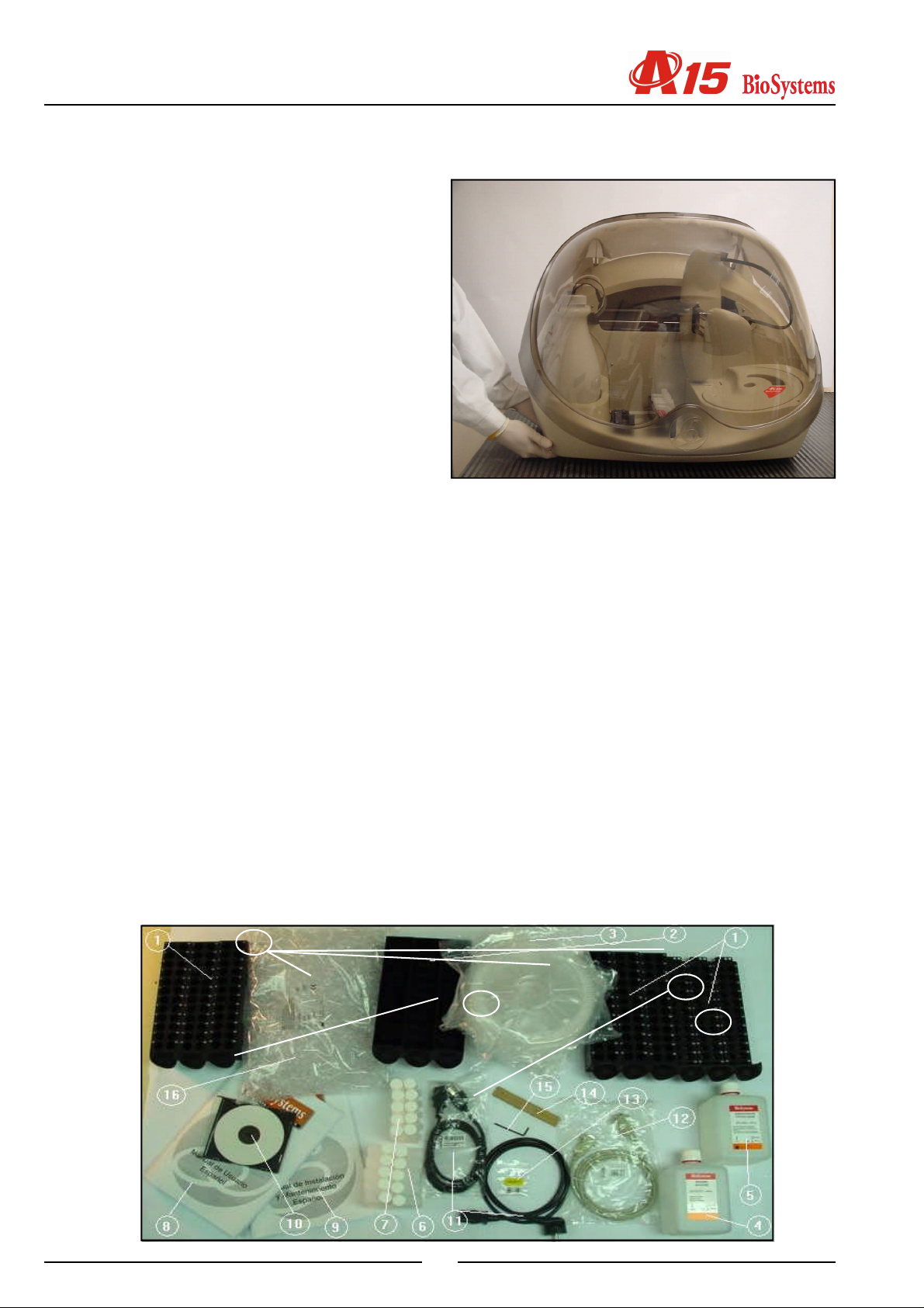
1.1. Unpacking
On receiving the instrument, check that the packaging is
in perfect condition and that the sealing is intact. Open the
box and carefully take out the contents. Follow the
indications on the unpacking instructions sheet. The
instrument weighs 45 kg and needs a minimum of two
people to move it. When lifting it, keep your back straight
to avoid injury. Grip it below the base, never by the top or
by the housing or any other of its elements. The base of
the analyser has two areas on each side, especially
designed for gripping it while moving it. It is recommendable
to use mechanical means, such as a fork lift, for
transporting the analyser. Do not throw the packaging material away, since it may be necessary for ensuring safe
transport if the analyser is reshipped or moved in a vehicle.
1.2. List of contents
The following is a list of the elements the user should find
on unpacking the analyser. Visually check that none of
them has been apparently damaged during transport.
1. Analyser
2. Unpacking instructions sheet.
3. Instrument Release Certificate
4. Boxes of accessories
5. Empty washing solution container with lid
Content of the box of accessories
1. Racks of samples (3+3+3)
2. Rack of reagents (3)
3. Reactions rotor (5)
4. Bottles of concentrated washing solution (1 bottle of
100mL)
5. Bottle of concentrated system liquid (1l)
6. Empty 50 ml bottles (10)
7. Empty 20 ml bottles (10)
8. User manual
9. Installation and maintenance manual
10.CD ROM with User programme
11.Network connection cables (European and American)
12.Serial channel cable for connection to the computer
13.Fuses
14.Metal rod for cleaning the needle
15. 2 mm Allen key
. Sample wells (1000)
1
13
14
8
5

Installation and maintenance manual
1.3. Identification of the main components
The main parts of the analyser are identified and numbered in the following figures and their associated lists.
16
15
14
12
17
15
16
15
18
17
15
14
8
9
13
7
11
11
13
4
3 5 7 10
2
4
5
20
10
8
9
3
6
1
10
6
8
9
7
21
1
3
172
6
5
2
3
4
1
1. Label showing brand and model
2. Rack tray
3. Sample racks
4. Reagent racks
5. Arm protector cover
6. Reactions rotor and reading
7. Needle washing station
8. Operating arm
9. Rotor cover
10.LED status indicator
11.Needle self-adjustment sensor
12.System liquid container
13.Waste container
14.System liquid tubes
15.Waste tubes
16.Grommet
17.Adjustable leg
1. Power point
2. Switch
3. Fuses
4. Identification label
5. Fans
6. RS-232 serial connections (PC) and USB auxiliary
connection
7. Back cover
8. Hydro-pneumatic elevators for the main cover
9. Base
10.General cover
6
2. Installation
With a view to guaranteeing optimum functioning of the
analyser, follow the installation instructions given in this
chapter carefully.
2.1. Warnings and precautions
The A15 analyser has been designed and constructed exclusively for professional use. The user must be adequately
trained for work in a clinical analysis laboratory and to use
an in vitro diagnostic analyser. Read this manual carefully
together with the User Manual and take heed of all the
warnings and precautions set forth in said manuals. The
manufacturer accepts no liability for damage caused by
incorrect use of the apparatus.
Warning
The user must check that the arm is completely
in parked position before raising the cover of
the analyser.
2.2. Location
operating arm. To adapt the analyser to the surface and
level it correctly, the front right leg is adjustable.
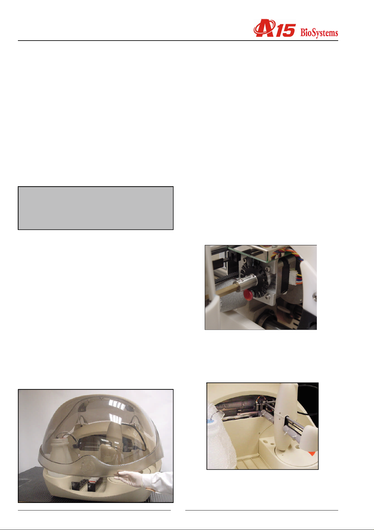
2.3. Opening the main cover
Lift the cover gently upwards by the front. The hydro-pneumatic hinge system enables the cover to be opened easily
and it stays open while the user works with the different
elements of the analyser. To close it, simply lower it gently
to its lowest position. The cover has an open sensor which
tells the analyser that it is open. In this case, the operating
arm does not carry out any preparation and stays in the
parked position to avoid injury to the user.
2.4. Unblocking the operating arm
To avoid damage during transport, the arm is immobilised
by 1 screw and two foamm pipes . These elements must
be removed for the arm to move freely. Simply unscrew it
using your fingers (no tools are required) as indicated on
the unpacking instructions sheet. Keep these screws and
The analyser must be located in a dry non-corrosive atmosphere. Relative humidity must not be higher than 75%.
It is recommended that room temperature is below 28ºC.
Avoid positioning it in draughts. Furthermore, the instrument must not be near sources of electromagnetic radiation (such as motors or centrifuges), or heat sources, or
receive direct, intense sunlight or artificial light.
It must be placed on a flat, spacious surface (minimum of
110 cm x 60 cm), with particular being taken to ensure that
there are no objects obstructing the air output of the ventilators (2 at the back and 1 on the base). Leave a minimum
space of 10 cm between the back of the analyser and the
wall or the nearest object. The surface must be sufficiently
robust and rigid to support the weight of the analyser (45
kg) and the force resulting from the rapid movements of the
the pipes next to the analyser so they can be repositioned
if it has to be moved using a transport vehicle or reshipped.
7
 Loading...