

Biostar TPower X79 Owner's Manual

TPOWER X79 Setup Manual
FCC Information and Copyright
This equipment has been tested and found to comply with the limits of a Class
B digital device, pursuant to Part 15 of the FCC Rules. These limits are designed
to provide reasonable protection against harmful interference in a residential
installation. This equipment generates, uses, and can radiate radio frequency
energy and, if not installed and used in accordance with the instructions, may
cause harmful interference to radio communications. There is no guarantee
that interference will not occur in a particular installation.
The vendor makes no representations or warranties with respect to the
contents here and specially disclaims any implied warranties of merchantability
or fitness for any purpose. Further the vendor reserves the right to revise this
publication and to make changes to the contents here without obligation to
notify any party beforehand.
Duplication of this publication, in part or in whole, is not allowed without first
obtaining the vendor’s approval in writing.
The content of this user’s manual is subject to be changed without notice and
we will not be responsible for any mistakes found in this user’s manual. All the
brand and product names are trademarks of their respective companies.

Table of Contents
Chapter 1: Introduction................................................................ 1
1.1 Before You Start.............................................................................................1
1.2 Package Checklist .........................................................................................1
1.3 Motherboard Features...................................................................................2
1.4 Rear Panel Connectors...................................................................................4
1.5 Motherboard Layout .....................................................................................5
Chapter 2: Hardware Installation .................................................. 6
2.1 Installing Central Processing Unit (CPU).......................................................6
2.2 FAN Headers..................................................................................................8
2.3 Installing System Memory..............................................................................9
2.4 Connectors AND Slots...................................................................................11
Chapter 3: Headers & Jumpers Setup........................................... 14
3.1 How to Setup Jumpers..................................................................................14
3.2 Detailed Settings..........................................................................................14
Chapter 4: RAID / AHCI Functions............................................... 22
4.1 Operating System........................................................................................ 22
4.2 Raid Arrays.................................................................................................. 23
4.3 How RAID Works .........................................................................................24
4.4 Smart Storage Caching ................................................................................28
Chapter 5: T-Power BIOS & Software........................................... 29
5.1 T-Power BIOS...............................................................................................29
5.2 T -Powe r So ftware ........................................................................................32
5.3 Extra Information........................................................................................ 39
5.4 AMI BIOS Bee p Code....................................................................................40
5.5 AMI BIOS Post Code .....................................................................................41
5.6 Troubleshooting........................................................................................... 43
Chapter 6: BIOS Update.............................................................. 44
6.1 BIOS Update Utility .....................................................................................44
6.2 Online Update Utility ..................................................................................46
6.3 BIOSTAR BIOS Flasher..................................................................................48
Appendix: SPEC In Other Languages............................................ 50
German .................................................................................................................... 50
French ..................................................................................................................... 52
Italian .....................................................................................................................54
Spanish .....................................................................................................................56
Portuguese ............................................................................................................... 58
Polish .....................................................................................................................60
Russian .....................................................................................................................62
Arabic ..................................................................................................................... 64
Japanese...................................................................................................................66

CHAPTER 1: INTRODUCTION
TPOWER X79
1.1 B
EFORE YOU START
Thank you for choosing our product. Before you start installing the
motherboard, please make sure you follow the instructions below:
Prepare a dry and stable working environment with
sufficient lighting.
Always disconnect the computer from power outlet
before operation.
Before you take the motherboard out from anti-static
bag, ground yourself properly by touching any safely
grounded appliance, or use grounded wrist strap to
remove the static charge.
Avoid touching the components on motherboard or the
rear side of the board unless necessary. Hold the board
on the edge, do not try to bend or flex the board.
Do not leave any unfastened small parts inside the
case after installation. Loose parts will cause short
circuits which may damage the equipment.
Keep the computer from dangerous area, such as heat
source, humid air and water.
1.2 PACKAGE CHECKLIST
Serial ATA Cable X 6
Rear I/O Panel for ATX Case X 1
User’s Manual X 1
Fully Setup Driver CD X 1
SLI Bridge X 1
CrossFireX Bridge X 1
Note: The package contents may be different due to area or your motherboard
version.
1
Motherboard Manual
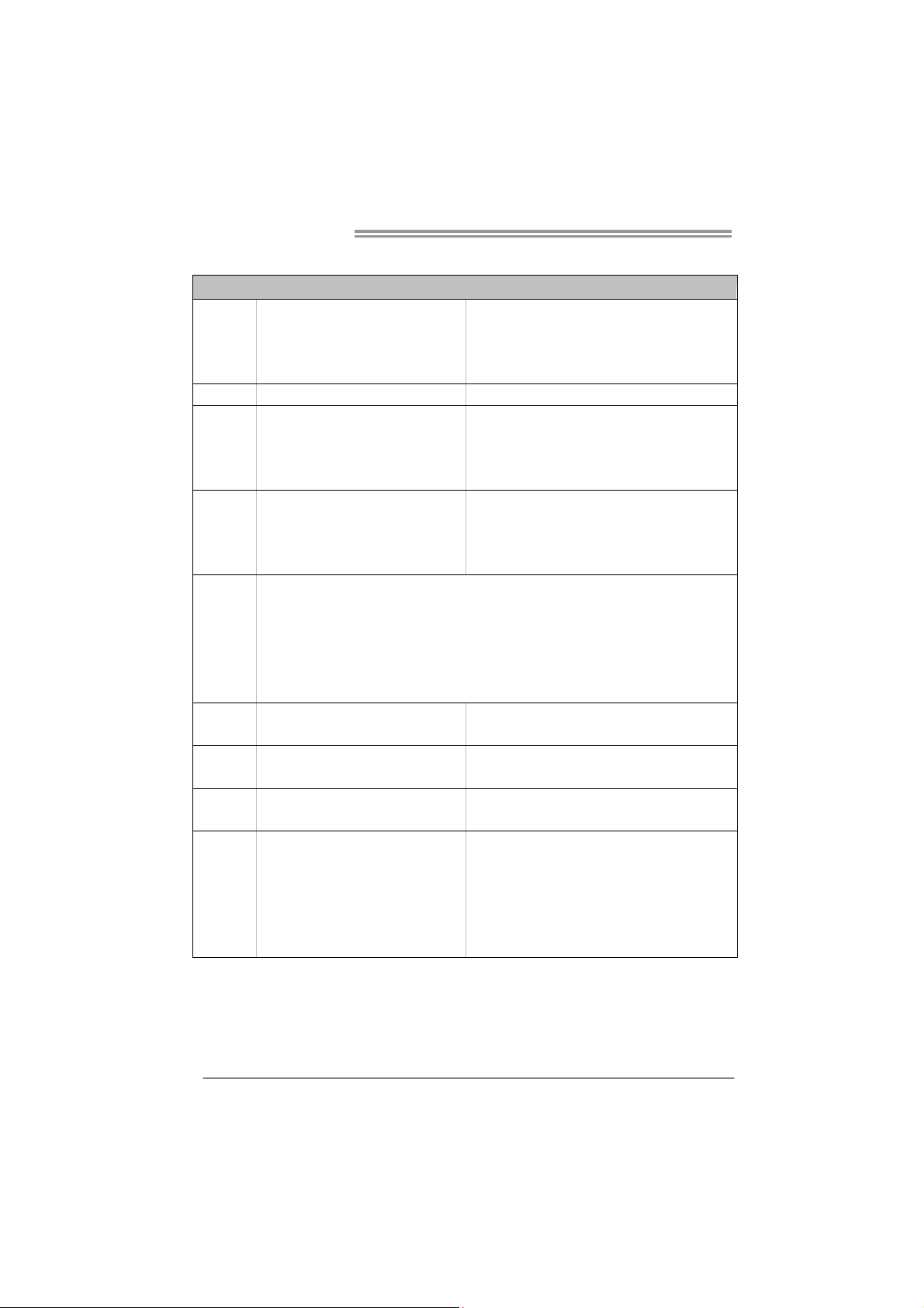
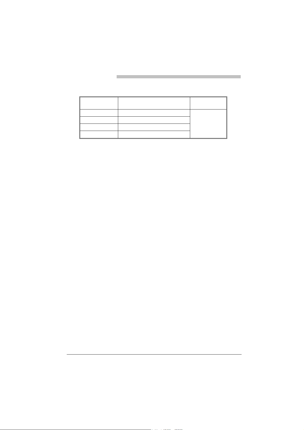
1.3 MOTHERBOARD FEATURES
SPEC
SOCKET 2011
CPU
Chipset Intel X79
Super I/O
Main
Memory
SATA
eSATA eS ATA x 1 (by Intel X79)
LAN Realtek RTL 8111E
Sound
Codec
Slots
Intel Sandybridge-E series / Core i7
Extreme / Core i7 process or
IT8728
Prov ides the most common ly used leg acy
Super I/O functionality.
Low Pin Count Interface
DIMM Slots x 4
Each DIMM supports 1GB / 2GB / 4GB /
8GB DDR3
Max Memory Capacity 32GB
SATA2 x 3 (by Intel X79)
SATA3 x 2 (by Intel X79)
SATA3 x 2 (by ASM1061)
ALC898
PCI slot x1
PCI Express Gen3 x16 slot (x16) x2
PCI Express Gen3 x16 slot (x8) x1
PCI Express Gen2 x1 slot x2
Supports Execute D isab le B it / Enhanced Int el
SpeedSt ep® / Inte l Ar ch itecture-64 / Extended
Memory 64 Technology / V irtualization Technology /
Hyp er T hr eading
En v iro n ment Co ntro l in it iatives ,
Hardware Monitor Controller
Fan Sp eed Contro ller
ITE's "S mart Guard ian" funct ion
Quad Ch anne l Mode DDR 3 me mo ry mod u le
Supports DDR3 2400(OC)/2133(OC)/1866(OC)/1600/
1333 /1066/800
Register ed DIMM and ECC D IMM is not supported
* Data transfer rates up to 3 Gb/s.
Support RAID 0 / 1 / 5 / 10 and Intel SRT
* Data transfer rates up to 6 Gb/s.
Support RAID 0 / 1 / 5 / 10 and Intel SRT
* Data transfer rates up to 6 Gb/s.
Support AHCI
Data transfer rates up to 3 Gb/s.
Support RAID 0 / 1 / 5 / 10 and Intel SRT
10 / 100 Mb/s / 1Gb/s auto negotiation
Half / Full duplex capability
7.1 channels audio out
High Definition Audio
Supports PCI expansion cards
Supports PCI-E Gen3 x16 expansion cards, Nvidia SLI
and AMD CrossFireX
Supports PCI-E Gen3 x16 expansion cards, Nvidia SLI
and AMD CrossFireX
Supports PCI-E Gen2 x1 expansion cards
2
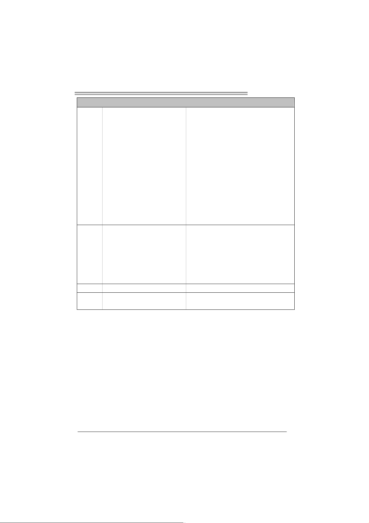
SPEC
SATA3 Connector x4
SATA2 Connector x3
Front Panel Connector x1
Front Audio Connector x1
S/PDIF out Connector x1
CPU Fan Header x1
On Board
Connector
Back Panel
I/O
Board Size 244 (W) x 305 (L) mm ATX
OS Support Windows XP / Vista / 7
System Fan Header x2
Clear CMOS Head er x1
USB3.0 Connector x1
USB2.0 Connector x2
Power Connector (24pin) x1
Power Connector (8pin) x2
Serial Port Connector x1
Consumer IR Connector x1
PS/2 Keybo ard x1
LAN Port x1
USB2.0 Port x2
USB3.0 Port x6
Audio Jack x6
eSATA Port x1
Optical +coaxial S/PDIF Out x1
TPOWER X79
Each connect or supports 1 SATA device
Each connect or supports 1 SATA device
Supports front panel f acilities
Supports front panel audio function
Supports digital audio out function
CPU Fan power supply (with Smart Fan function)
System Fan Power supply
Restore CMOS data to factory default
Each connector supports 2 front panel USB3.0 ports
Each connector supports 2 front panel USB2.0 ports
Connects to Power supply
Connects to Power supply
Connects to RS-232 Port
Supports infrared function
Connects to PS/2 Keyboard
Connect to RJ-45 ethernet cab le
Connect t o US B devices
Connect t o US B devices
Provide Audio-In/Out and microphone connection
Connect to SATA devices
Provides digital audio out function
Biostar Reserves the right to add or remove support for
any OS with or without notice
3
Motherboard Manual
2
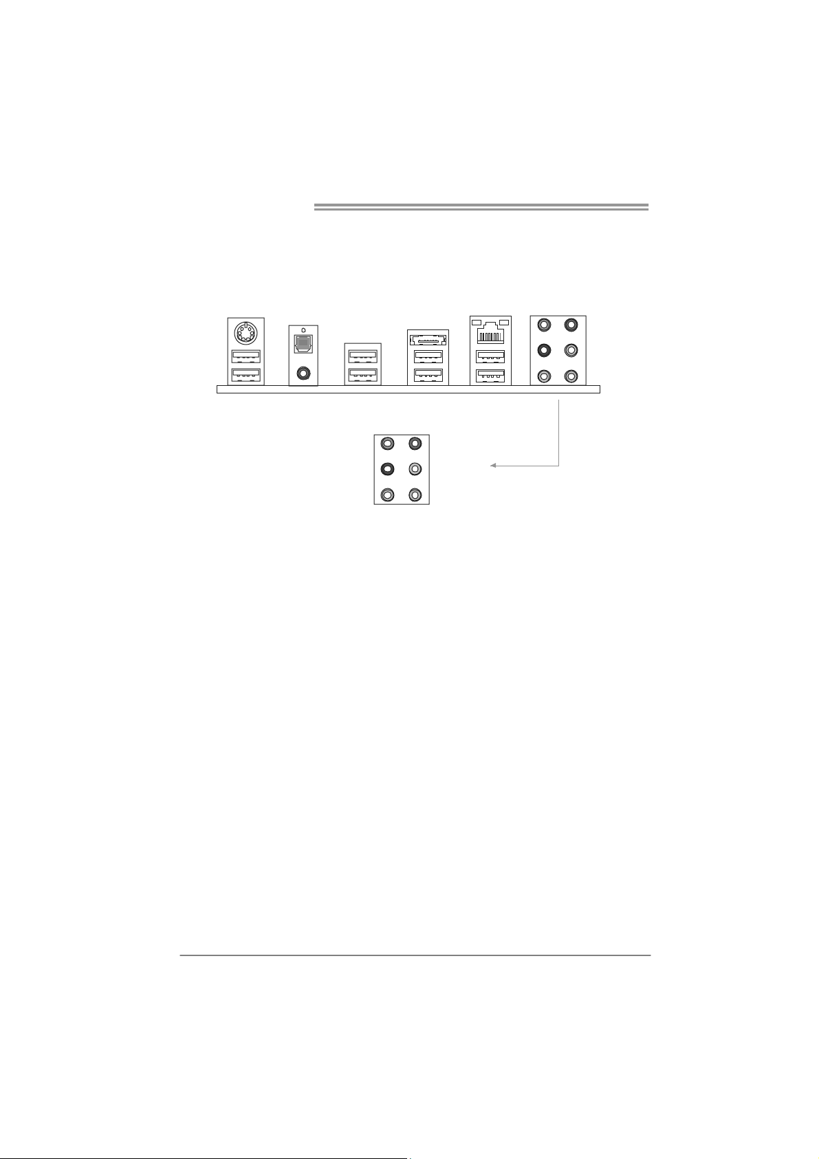
1.4 REAR PANEL CONNECTORS
PS/
Keyboard
USB2.0X2
S/PDIF Out
RCA
USB3.0X2
Center
Rear
Side
eSATA
LAN
USB3.0X2 USB3.0X2
Line In
Line Out
Mic In
4
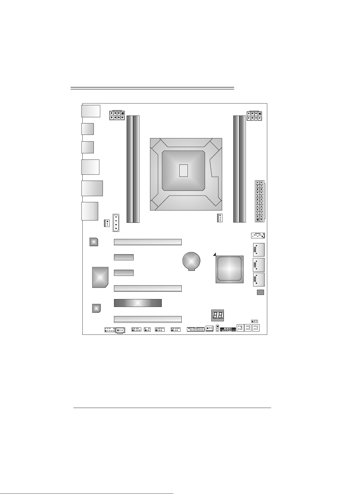
1.5 MOTHERBOARD LAYOUT
USB_KBMS1
TPOWER X79
SPDIF1
USB3_0
DUALUSB_
ESATA1
RJ45USB1
AUDIO2
LA N
Super
I/O
SYS_FAN2
ATXPWR2
J1
PEX16_1
PEX1_ 1
PEX1_ 2
PEX16_2
ATXPWR3
Socket 2011
DDR3_A1
DDR3_B1
CPU 1
CPU_FAN1
BAT1
Intel
DDR3 _D1
DDR3 _C1
ATXPWR1
SATA1
SATA2SAT A3SATA4
X79
BIOS
CODEC
F_AUDIOF1
Note: represents the 1■
PCI1
PEX16_3
JSPDIF_OUT1
JFRONT_USB3_1
J_COM1 CIR1 F_USB2F_USB1 SYS_FAN1
st
pin.
JCMOS1
PANEL1
CL_CMOS_
BTN1
RSTSW1
ME_RECOVERY1
PWRSW 1
5
Motherboard Manual
CHAPTER 2: HARDWARE INSTALLATION
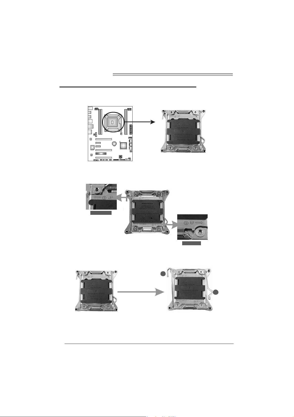
2.1 I
NSTALLING CENTRAL PROCESSING UNIT (CPU)
Step 1: Locate and identify the locking lever, UNLOCK 1 LIFT and LOCK
1 LIFT.
UNLOCK 1 LIFT
LOCK 1 LIFT
Step 2: First, pull the locking lever UNLOCK 1 LIFT out from the socket;
next, pull the LOCK 1 LIFT out from the socket.
1
6
2
TPOWER X79
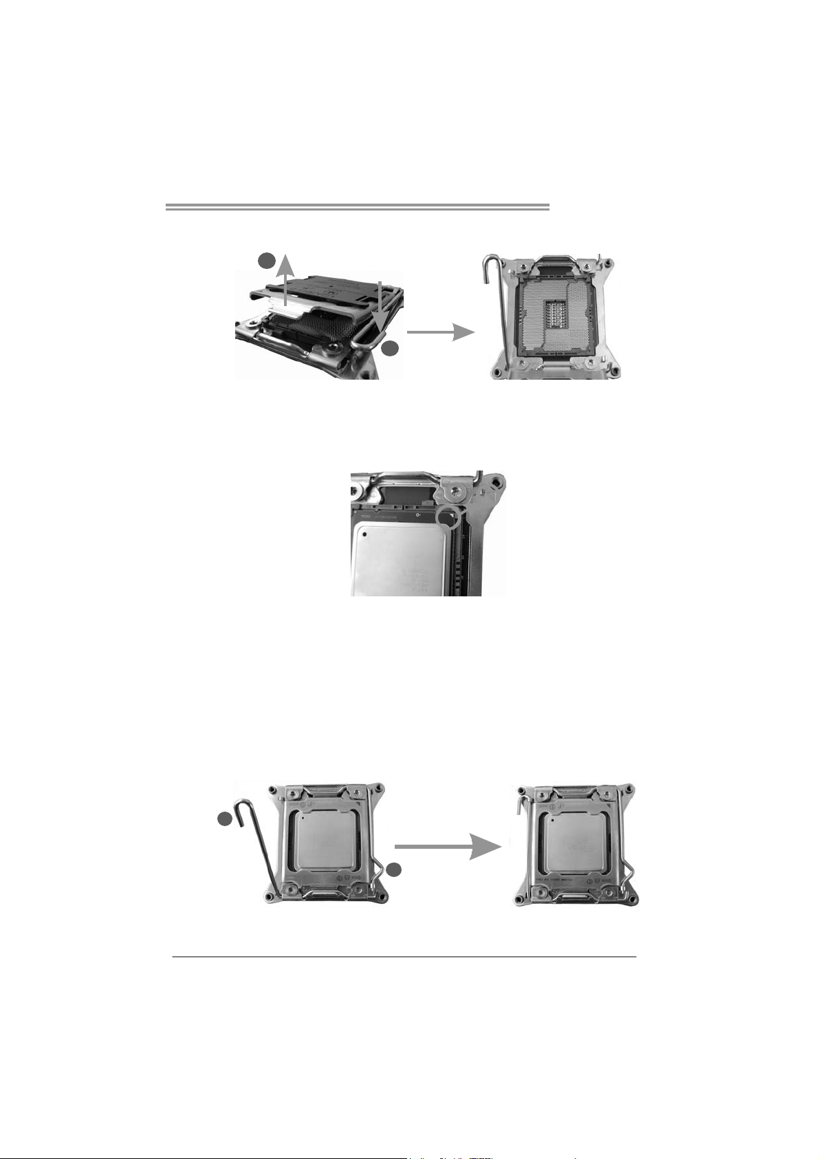
Step 3: Pushing down the hook of left locking lever to lift the load plate,
and then remove the Protection Cap.
2
1
Step 4: Locate the triangular cut edge on the socket, and hold the CPU
firmly, orientating the golden dot on the CPU forwards to this
socket triangular cut edge. The CPU will fit only in the correct
orientation.
Special Notice:
After the CPU installation, please make good preservation of the
Protection Cap for future use. When the CPU is removed, cover the
Protection Cap on the empty socket to ensure pin legs won’t be
damaged.
Step 5: Reversely, lower the locking lever LOCK 1 LIFT to locked position,
next the UNLOCK 1 LIFT to locked position, and then complete
the installation.
2
1
7
Motherboard Manual
Step 6 Put the CPU Fan and heatsink assembly on the CPU and buckle it
on the retention frame. Connect the CPU FAN power cable into
the CPU_FAN1 to complete the installation.
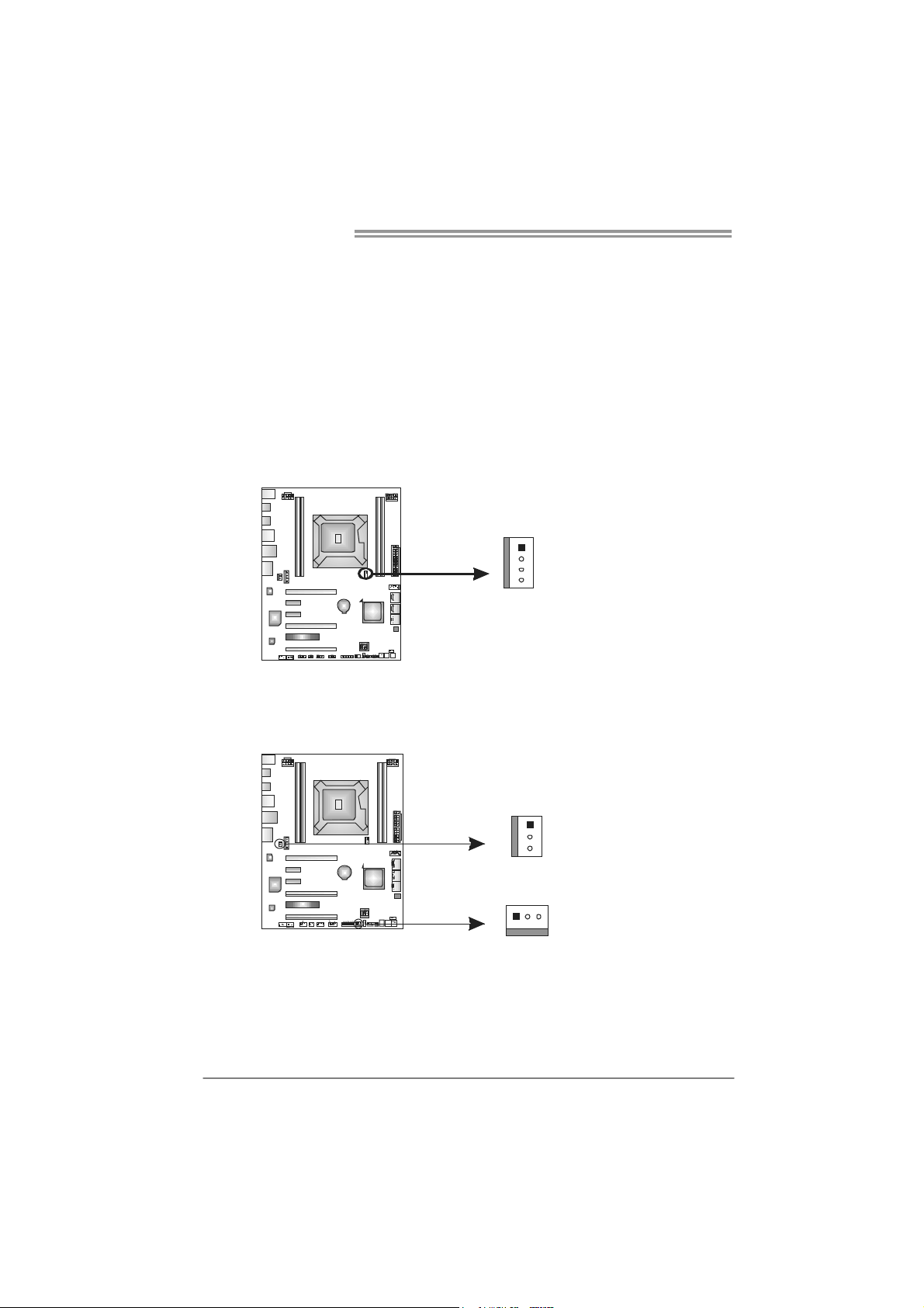
2.2 FAN HEADERS
These fan headers support cooling-fans built in the computer. The fan
cable and connector may be different according to the fan manufact urer.
Connect the fan cable to the connector while matching the black wire to
pin#1.
CPU_FAN1: CPU Fan Header
Pin
Assignment
1 Ground
1
4
2 +12V
3
FAN RPM r at e
sense
4 Smart Fan
Control
SYS_FAN1: NorthBridge Fan Header
SYS_FAN2: System Fan Header
Note:
The SYSFAN1/SYSFAN2 support 3-pin head connectors, and the CPU_FAN1, 4-pin
head connector. When connecting with wires onto connectors, please note that the red
wire is the positive and should be connected to pin#2, and the black wire is Ground and
should be co nnected to GND.
8
SYS_FAN2
1
3
SYS_FAN1
31
Pin
Assignment
1 Ground
2 +12V
3 FAN RPM rate
sense
TPOWER X79
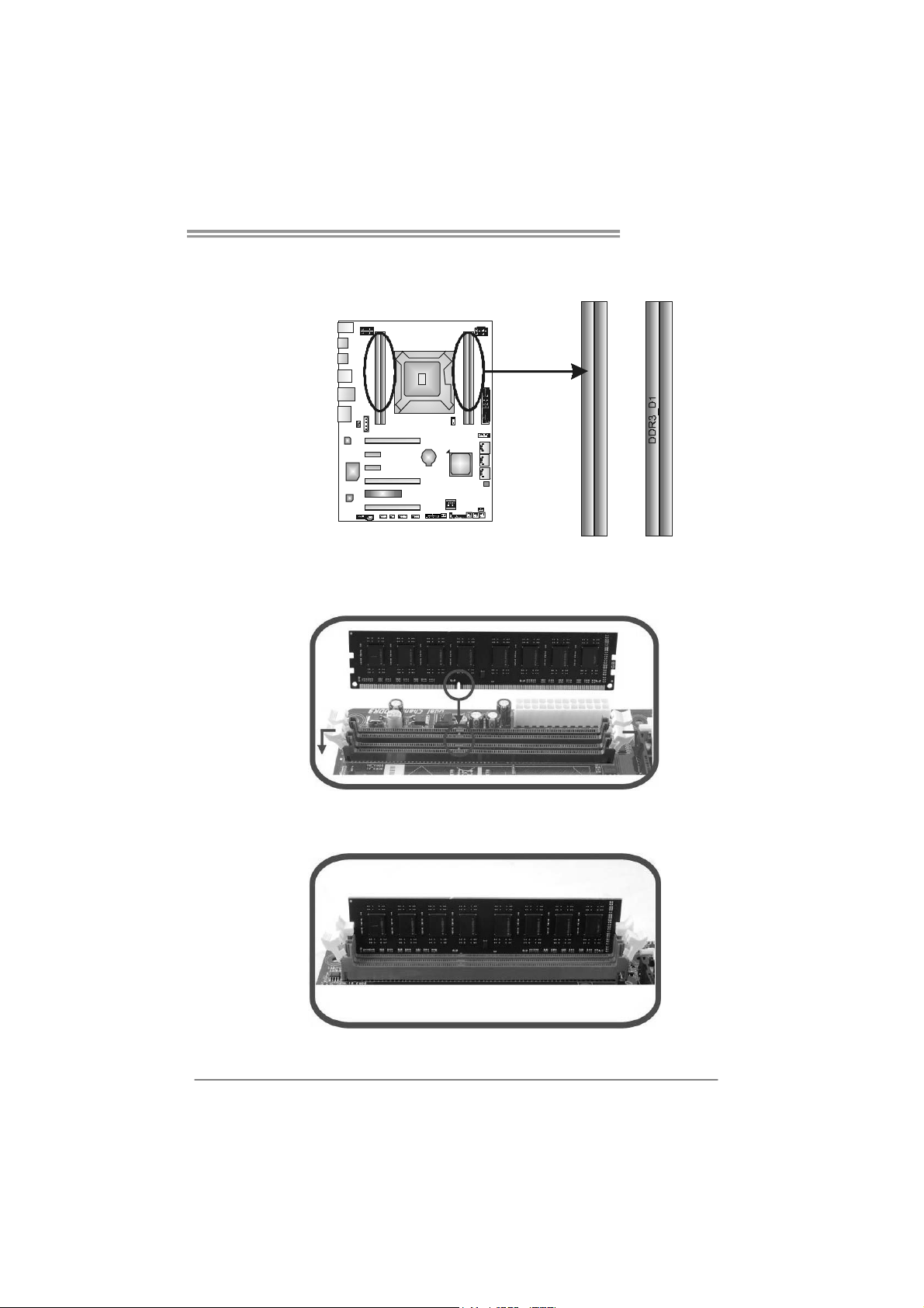
2.3 INSTALLING SYSTEM MEMORY
A. Memory Modules
DDR3_A1
DDR3_B1
1. Unlock a DIMM slot by pressing the retaining clips outward. Align a
DIMM on the slot such that the notch on the DIMM matches the
break on the Slot.
DDR3_C1
2. Insert the DIMM vertically and firmly into the slot until the retaining
chip snap back in place and the DIMM is properly seated.
9
Motherboard Manual
B. Memory Capacity
DIMM Socket
Location
DDR3_A1 512MB/1GB/2GB/4GB/8GB
DDR3_B1 512MB/1GB/2GB/4GB/8GB
DDR3_C1 512MB/1GB/2GB/4GB/8GB
DDR3_D1 512MB/1GB/2GB/4GB/8GB
DDR3 Module
Total Mem ory
Size
Max is 32GB.
10
2.4 CONNECTORS AND SLOTS
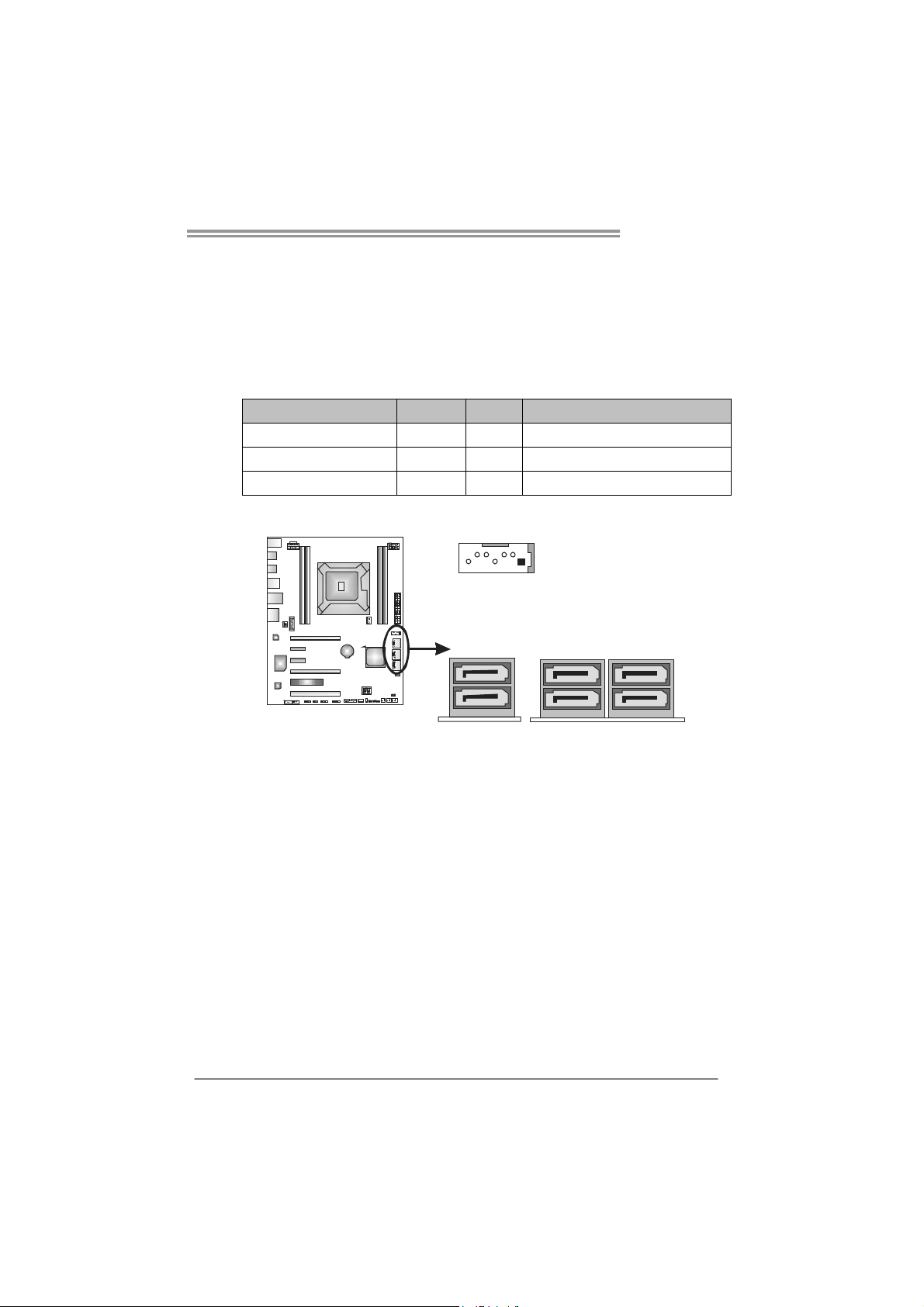
SATA1~SATA4: Serial ATA Connectors
This motherboard provides several SATA controllers for connecting to SATA
devices with respective spec and transfer rates as bellows:
CONNECTOR BY CHIP SPEED Support
SATA1/SATA2-U/SATA2-L Intel X79 3 Gb/s. RAID 0 / 1 / 5 / 10 and Intel SRT
SATA3-U/SATA3-L Intel X79 6 Gb/s. RAID 0 / 1 / 5 / 10 and Intel SRT
SATA4-U/SATA4-L ASM1061 6 Gb/s. AHCI
TPOWER X79
SATA1
SATA4-
SATA L
U
4-
(By ASM1061)
SAT A3- SA TA2SAT A L SA T A L
UU
3- 2-
(By Intel X79)
11
Motherboard Manual
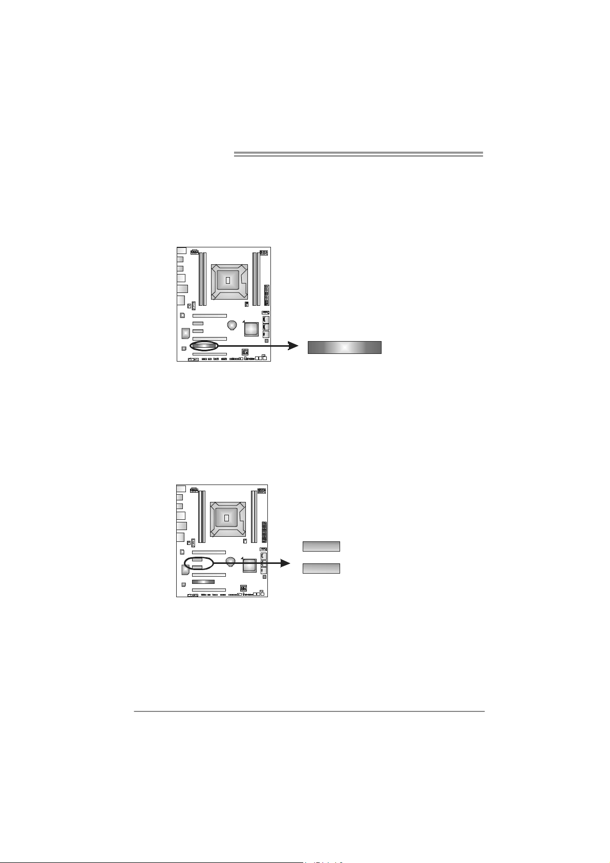
PCI1: Peripheral Component Interconnect Slot
This motherboard is equipped with 1 standard PCI slots. PCI stands for
Peripheral Component Interconnect, and it is a bus standard for expansion
cards. This PCI slot is designated as 32 bits.
PEX1_1: PCI-Express Gen2 x2 Slots
- PCI-Express 2.0 compliant.
- Data transfer bandwidth up to 500MB/s per direction; 1GB/s in total.
PCI1
12
PEX1_1
PEX1_2
TPOWER X79
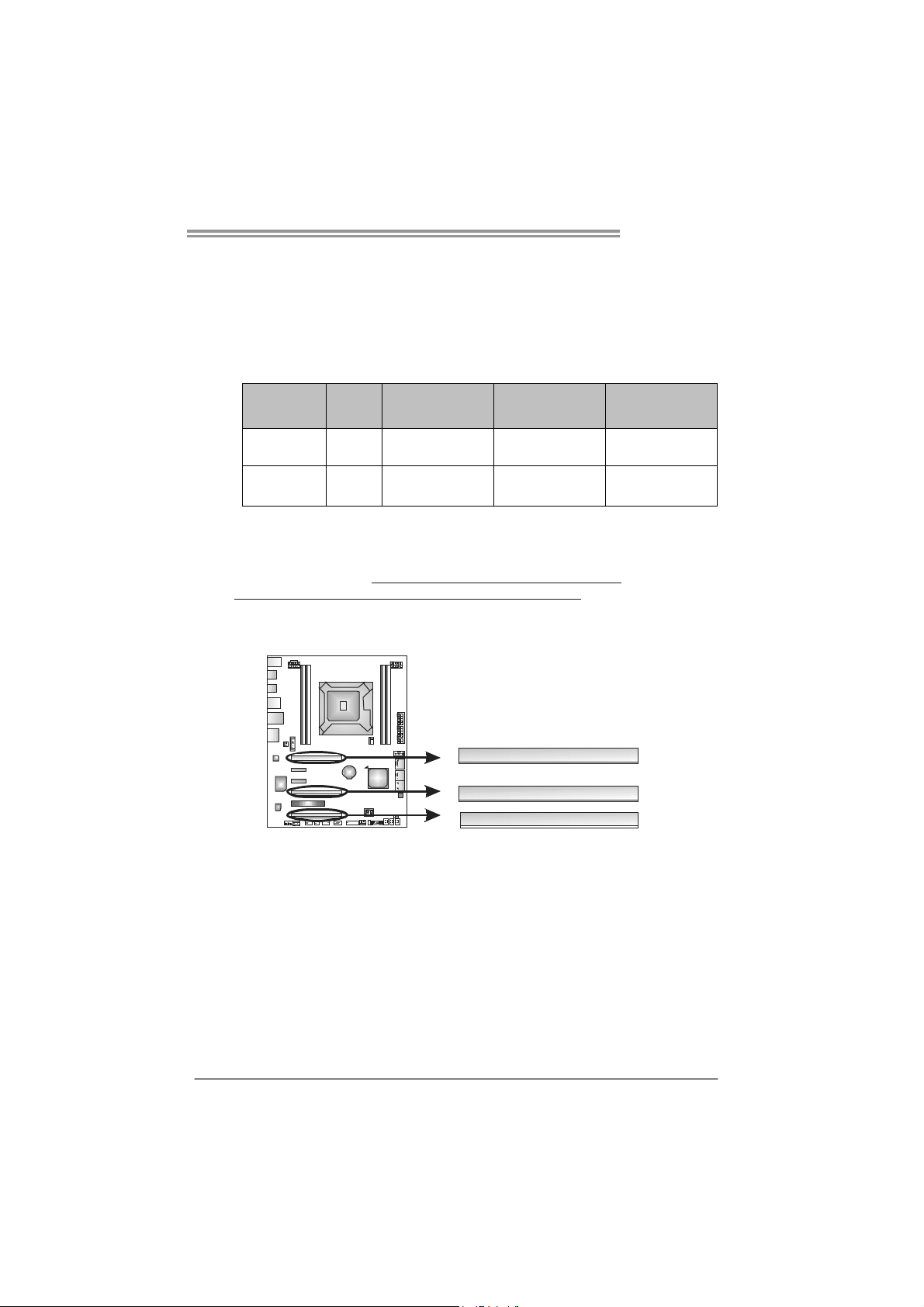
PEX16_1 & PEX16_2: PCI-Express Gen3 x16 (x16) (Nvidia SLI and
AMD CrossFireX) Slots
PEX16_3: PCI-Express Gen3 x16 (x8) (Nvidia SLI and AMD
CrossFireX) Slot
Slot Speed
PEX16_1 /
PEX16_2
PEX16_3 X 8 PCI-Express 3.0 8GB 16GB
X 16 PCI-Express 3.0 16GB 32GB
PCI e
Architecture
Note:
For more details about Nvidia SLI and AMD CrossFireX, please access the
website, respectively:
http://www.nvidia.com/page/support.html, and
http://support.amd.com/us/Pages/AMDSupportHub.aspx
Bandwidth
Per Direction
.
Bandwidth
Total
PEX16_1
PEX16_2
PEX16_3
13

Motherboard Manual
CHAPTER 3: HEADERS & JUMPERS SETUP
3.1 H
OW TO SETUP JUMPERS
The illustration shows how to set up jumpers. When the jumper cap is
placed on pins, the jumper is “close”, if not, that means the jumper is
“open”.
Pin opened Pin closed Pin1-2 closed
3.2 DETAILED SETTINGS
JPANEL1: Front Panel Header
This 16-pin connector includes Power-on, Reset, HDD LED, Power LED, and
speaker connection. It allows user to connect the PC case’s front panel switch
functions.
PW R_LED
On/Off
++
9
1
SPK
+--
HLED
RST
16
8
14
Pin Assignment Function Pin Assignment Function
1 +5V 9 N/A
2 N/A 10 N/A
3 N/ A 11 N/ A N/ A
4 Speaker
5 HDD LED (+) 13 Power LED (+)
6 HDD LED (-)
7 Ground 15 Power button
8 Reset control
Speaker
Connector
Hard drive
LED
Reset button
12 Power LED (+)
14 Power LED (-)
16 Ground
N/A
Power LED
Power-on button
TPOWER X79
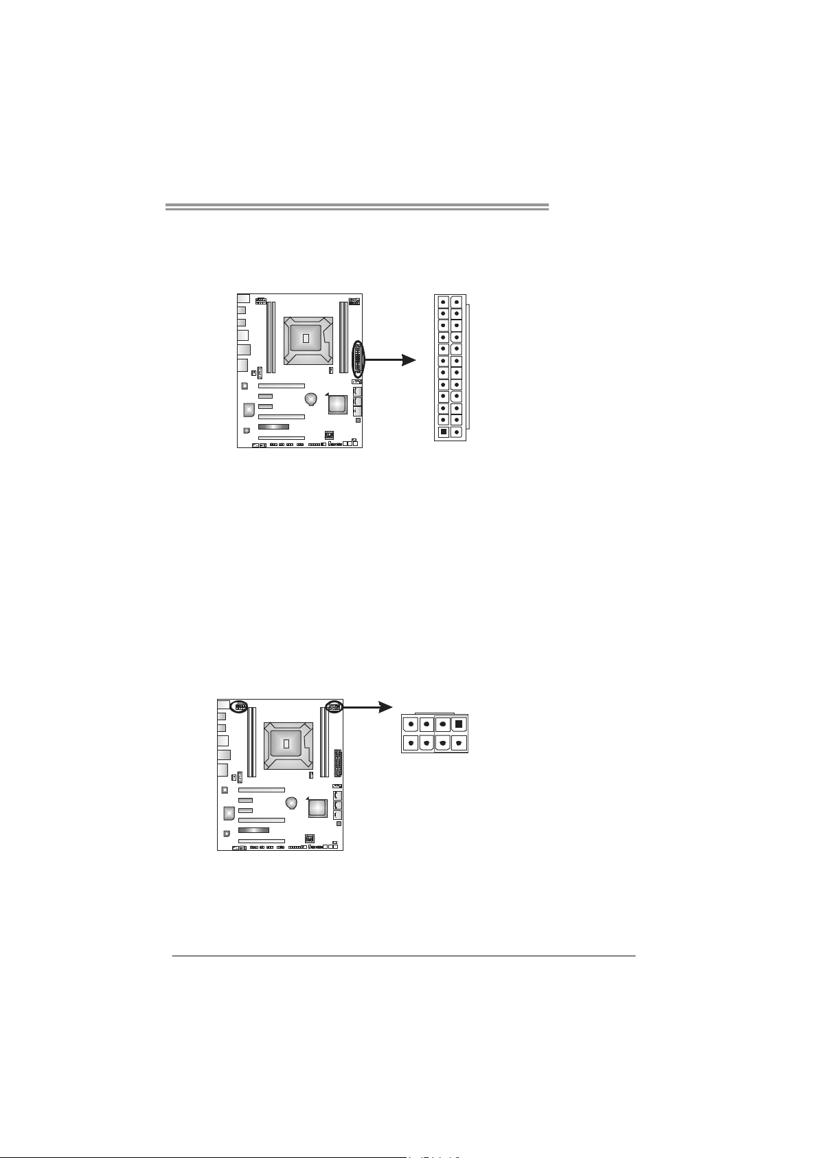
ATXP W R1 (12V1 ): ATX P ower Source Connector
This connector allows user to connect 24-pin power connector on the ATX
power supply. (Note: +12V Current Limit > 12A)
12
1
Pin Assignment Pin Assignment
13 +3.3V 1 +3.3V
14 -12V 2 +3.3V
15 Ground 3 Ground
16 PS_ON 4 +5V
17 Ground 5 Ground
18 Ground 6 +5V
19 Ground 7 Ground
20 NC 8 PW_OK
21 +5V 9 Standby Voltage+5V
22 +5V 10 +12V
23 +5V 11 +12V
24 Ground 12 +3.3V
24
13
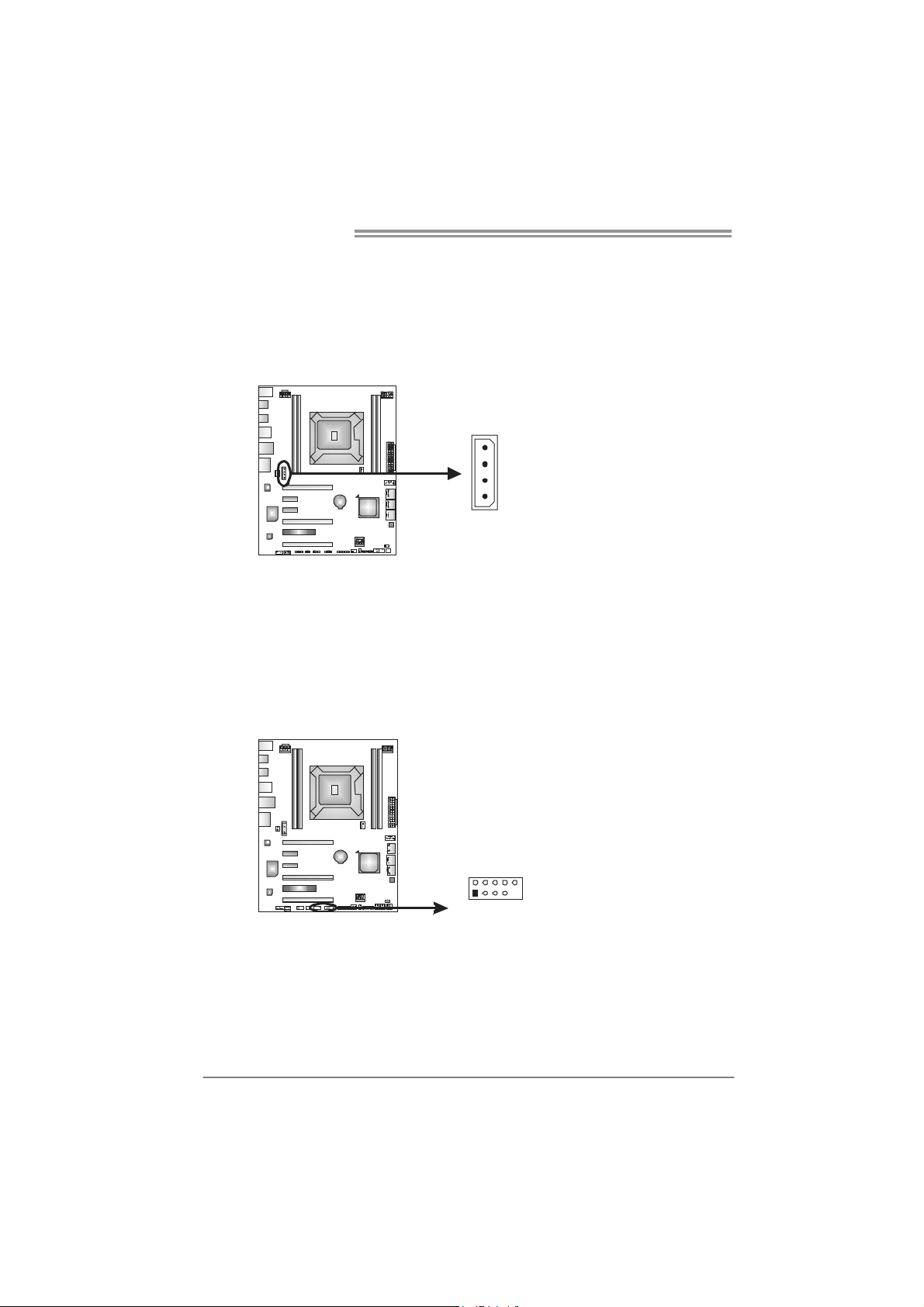
ATXP W R2~3 (12V2) : ATX Power Source Connectors
These connectors provide +12V to CPU power circuit. (Note: +12V Current
Limit > 17A ~ 21A)
4
5
1
8
Pin Assignment
1 +12V
2 +12V
3 +12V
4 +12V
5 Ground
6 Ground
7 Ground
8 Ground
Note:
Plug in either ATXPWR2 or ATXPWR3 connector to power on the system. It is
recommended that both ATXPWR2 and ATXPWR3 connectors s hould be plugged in
when overclocking.
If the CPU power plug is 4-pin, please plug it into Pin 1-2-5-6 of ATXPWR2/3.
15
Motherboard Manual
J1: Auxiliary Power for Graphics
This connector is an auxiliary power connection for graphics cards. Exclusive
power for the graphics card provides better graphics performance.
4
1
F_USB1/F_USB2: Headers for USB 2.0 Ports at Front Panel
Theses headers allow user to connect additional USB cable on the PC front
panel. They also can be connected with internal USB devices, like USB card
reader.
F_ USB2USB 1 F_
2910
1
Pin
Assignment
1 +12V
2 Ground
3 Ground
4 VCC
Pin
Assignment
1 +5V (fused)
2 +5V (fused)
3 USB4 USB5 USB+
6 USB+
7 Ground
8 Ground
9 Key
10 NC
16
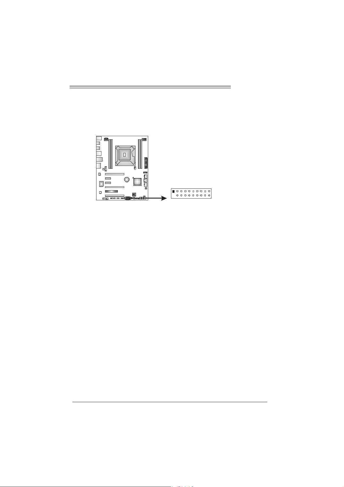
JFRONT_USB3_1: Header for USB 3.0 Ports at Front Panel
This header allows user to connect additional USB cable on the PC front panel,
and also can be connected with internal USB devices, like USB card reader.
TPOWER X79
1
20 11
Pin Assignment Pin Assignment
1 VBUS0 11 D2+
2 SSRX1- 12 D23 SSRX1+ 13 Ground
4 Ground 14 SSTX2+
5 SSTX1- 15 SSTX26 SSTX1+ 16 Ground
7 Ground 17 SSRX2+
8 D1- 18 SSRX29 D1+ 19 VBUS1
10 ID 20 Key
10
17

Motherboard Manual
F_AUDIOF1: Front Panel Audio Header
This header allows user to connect the front audio output cable with the PC front
panel. This header supports HD and AC’97 audio front panel connector.
2
10
1
9
Pin Assignment Pin Assignment
1 Mic Left in 1 Mic In
2 Ground 2 Ground
3 Mic Right in 3 Mic Power
4 GPIO 4 Audio Power
5 Right line in 5 RT Line Out
6 Jack Sense 6 RT Line Out
7 Front Sense 7 Reserved
8 Key 8 Key
9 Left line in 9 LFT Line Out
10 Jack Sense 10
HD Audio AC’97
LFT Line Out
Note: It is recommended that you connect a high-definition front panel audio module to
this connector to avail of the motherboard's high definition audio capability.
18
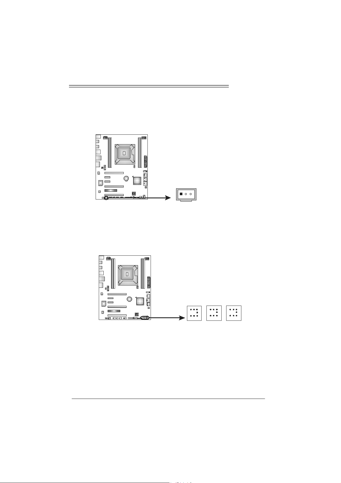
JSPDIFOUT1: Digital Audio-out Connectors
The JSPDIFOUT1 is for connecting the PCI bracket SPDIF output.
JSPDIFOUT1
On-Board Buttons
There are 3 on-board buttons.
TPOWER X79
Pin
Assignment
1 +5V
2 SPDIF_OUT
3 Ground
3
1
CL_CMOS_BTN1
RSTSW1
PWRSW1
PWRSW1:
This is an on-board Power Switch button.
RSTSW1:
This is an on-board Reset button.
CL_CMOS_BTN1: Clear CMOS Header
You can use this jumper to reset the BIOS to default.
19
 Loading...