

Biostar TPower I55 Owner's Manual

TPower I55 Setup Manual
FCC Information and Copyright
This equipment has been tested and found to comply with the limits of a Class
B digital device, pursuant to Part 15 of the FCC Rules. These limits are designed
to provide reasonable protection against harmful interference in a residential
installation. This equipment generates, uses, and can radiate radio frequency
energy and, if not installed and used in accordance with the instructions, may
cause harmful interference to radio communications. There is no guarantee
that interference will not occur in a particular installation.
The vendor makes no representations or warranties with respect to the
contents here and specially disclaims any implied warranties of merchantability
or fitness for any purpose. Further the vendor reserves the right to revise this
publication and to make changes to the contents here without obligation to
notify any party beforehand.
Duplication of this publication, in part or in whole, is not allowed without first
obtaining the vendor’s approval in writing.
The content of this user’s manual is subject to be changed without notice and
we will not be responsible for any mistakes found in this user’s manual. All the
brand and product names are trademarks of their respective companies.

Table of Contents
Chapter 1: Introduction ........................................ 1
1.1 Before You Start......................................................................................... 1
1.2 Package Checklist..................................................................................... 1
1.3 Motherboard Features.............................................................................. 2
1.4 Rear Panel Connectors.............................................................................. 3
1.5 Motherboard Layout................................................................................. 4
Chapter 2: Hardware Installation .......................... 5
2.1 Installing Central Processing Unit (CPU) ............................................... 5
2.2 FAN Headers.............................................................................................. 7
2.3 Installing System Memory ........................................................................ 8
2.4 Connectors and Slots................................................................................ 10
Chapter 3: Headers & Jumpers Setup .................. 13
3.1 How to Setup Jumpers............................................................................. 14
3.2 Detail Settings .......................................................................................... 14
Chapter 4: RAID Functions .................................. 20
4.1 Operating System.................................................................................... 20
4.2 Raid Arrays............................................................................................... 20
4.3 How RAID Works ..................................................................................... 20
Chapter 5: T-Power BIOS & Software .................. 24
5.1 T-Power BIOS ........................................................................................... 24
5.2 T-Power Software .................................................................................... 32
Chapter 6: Useful Help ........................................ 41
6.1 Driver Installation Note.......................................................................... 42
6.2 Extra Information.................................................................................... 43
6.3 AMI BIOS Beep Code............................................................................... 44
6.4 AMI BIOS Post Code................................................................................. 45
6.5 Troubleshooting....................................................................................... 47
Appendix: SPEC In Other Languages ................... 48
German.................................................................................................................. 48
French .................................................................................................................... 50
Italian..................................................................................................................... 52
Spanish ................................................................................................................... 54
Portugue se ............................................................................................................ 56
Polish...................................................................................................................... 58
Russian ................................................................................................................... 60
Arabic..................................................................................................................... 62
Japanese ................................................................................................................ 64

TPower I55
CHAPTER 1: INTRODUCTION
1.1 B
EFORE YOU START
Thank you for choosing our product. Before you start installing the
motherboard, please make sure you follow the instructions below:
Prepare a dry and stable working environment with
sufficient lighting.
Always disconnect the computer from power outlet
before operation.
Before you take the motherboard out from anti-static
bag, ground yourself properly by touching any safely
grounded appliance, or use grounded wrist strap to
remove the static charge.
Avoid touching the components on motherboard or the
rear side of the board unless necessary. Hold the board
on the edge, do not try to bend or flex the board.
Do not leave any unfastened small parts inside the
case after installation. Loose parts will cause short
circuits which may damage the equipment.
Keep the computer from dangerous area, such as heat
source, humid air and water.
The operating temperatures of the computer should be
0 to 45 degrees Celsius.
1.2 PACKAGE CHECKLIST
HDD Cable X 1
Serial ATA Cable X 6
Serial ATA Power Cable X 6
Rear I/O Panel for ATX Case X 1
User’s Manual X 1
Fully Setup Driver CD X 1
FDD Cable X 1 (optional)
USB 2.0 Cable X1 (optional)
S/PDIF out Cable X 1 (optional)
SLI Bridge X 1
CFX Bridge X1
Note: The package contents may be different due to area or your motherboard version.
1

Motherboard Manual
1.3 MOTHERBOARD FEATURES
CPU
Chipset
Super I/O
Main
Memory
IDE
SATA II
eSATA
LAN
Sound
Codec
IEEE 1394
Slots
On Board
Connector
Socket 1156
Int e l Core i7 / i5 pro ces s or
Intel P55
IT8720
Prov ides the most common ly used leg acy
Super I/O functionality.
Low Pin Count Interface
DIMM Slots x 4
Each DIMM supports 512 MB / 1GB / 2GB /
4GB DDR3
Max Memory Capicity 16GB
JMB363
P55
JMB363
Realtek RTL 8111DL x1
Intel 82578 PHY x1
ALC888S
LSI FW322 1394a
PCI slot x2 Supports PCI expansion cards
PCI Express Gen2 x16 slot x2 Supports PCI-E Gen2 x16 expansion cards
PCI Express Gen2 x4 slot x1 Supports PCI-E Gen2 x4 expansion card
PCI Express Gen2 x1 slot x1 Supports PCI-E Gen2 x1 expansion card
Floppy Connector x1 Each connector supports 2 Floppy devices
IDE Conn ecto r x1 Each connector support s 2 IDE dev ices
SATA Connector x6 Each connector supports 1 SATA device
Front Panel Connector x1 Supports front panel facilit ies
SPEC
Supports Execute D isab le B it / Enhanced Int el
SpeedSt ep® / Inte l Ar chitecture-64 / Extended
Memory 64 Technology / V irtualization Technology /
Hyp er T hr eading
En v iro n ment Co ntro l init iatives,
Hardware Monitor Controller
Fan Sp eed Contro ller
ITE's "S mart Guard ian" funct ion
Dual Chan ne l Mode DDR3 memo ry mod u le
Supports DDR3 2000(OC) / 1866(OC) / 1600(OC) /
1333 / 1066 / 800
Register ed DIMM and ECC D IMM is not suppo rted
Ultra DMA 33 / 66 / 100 / 133 Bus Master Mode
supports PIO Mode 0~4
Data transfer rates up to 3 Gb/s.
SATA Version 2.0 spec ific at ion co mpliant .
RAID 0 / 1 / 5 / 10 support
Data transfer rates up to 3 Gb/s.
SATA Version 2.0 spec ific at ion co mpliant .
Port-Multiplier/RAID 0,1 support
10 / 100 Mb/s / 1Gb/s auto negotiation
Half / Full duplex capability
7.1 channels audio out
High Definition Audio
2
SPEC
Front Audio Connector x1 Supports front panel audio function
CD-in Connector x1 Supports CD audio-in function
S/PDIF out Connector x1 Supports digital audio out function
CPU Fan Header x1 CPU Fan power supply (with Smart Fan function)
System Fan Header x2 System Fan Power supply
Clear CMOS Head er x1 Restore CMOS data to factory def au lt
USB Connector x3 Each connector suppo rts 2 front panel USB ports
IEEE 1394 Connector x1 Connects to IEEE 1394 device
Power Connector (24pin) x1 Connects to Power supply
Power Connector (8pin) x1 Connects to Power supply
PS/2 Keybo ard x1
LAN Port x2
Back Panel
I/O
Board Size 244 (W) x 305 (L) mm ATX
OS Support Windows XP / Vista 32 / Vista 64
USB Port x8
Audio Jack x6
eSATA Port x2
1394 Port x1
Optical +coaxial S/PDIF Out x1
TPower I55
Connects to PS/2 Keyboard
Connect to RJ-45 ethernet cab le
Connect t o US B devices
Provide Audio-In/Out and microphone connection
Connect to SATA devices
Connects to IEEE 1394 device
Provides digital audio out function
Biostar reserves the right to add or remove support for
any OS with or without notice
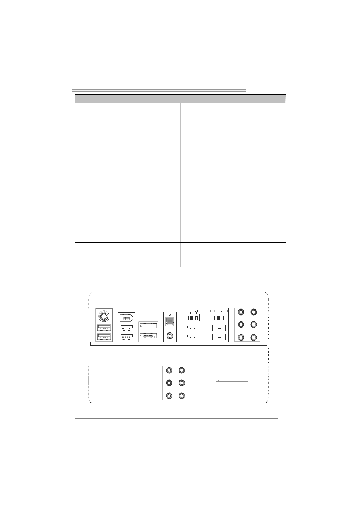
1.4 REAR PANEL CONNECTORS
PS/2
Keyboard
IEEE 1394
USBX2
Optical +coaxial
S/PDIF Ou t
eSATAX2USBX2
Center
Rear
Side
LAN
USBX2
Line In
Line Out
Mic In
LAN
USBX2
3
Motherboard Manual
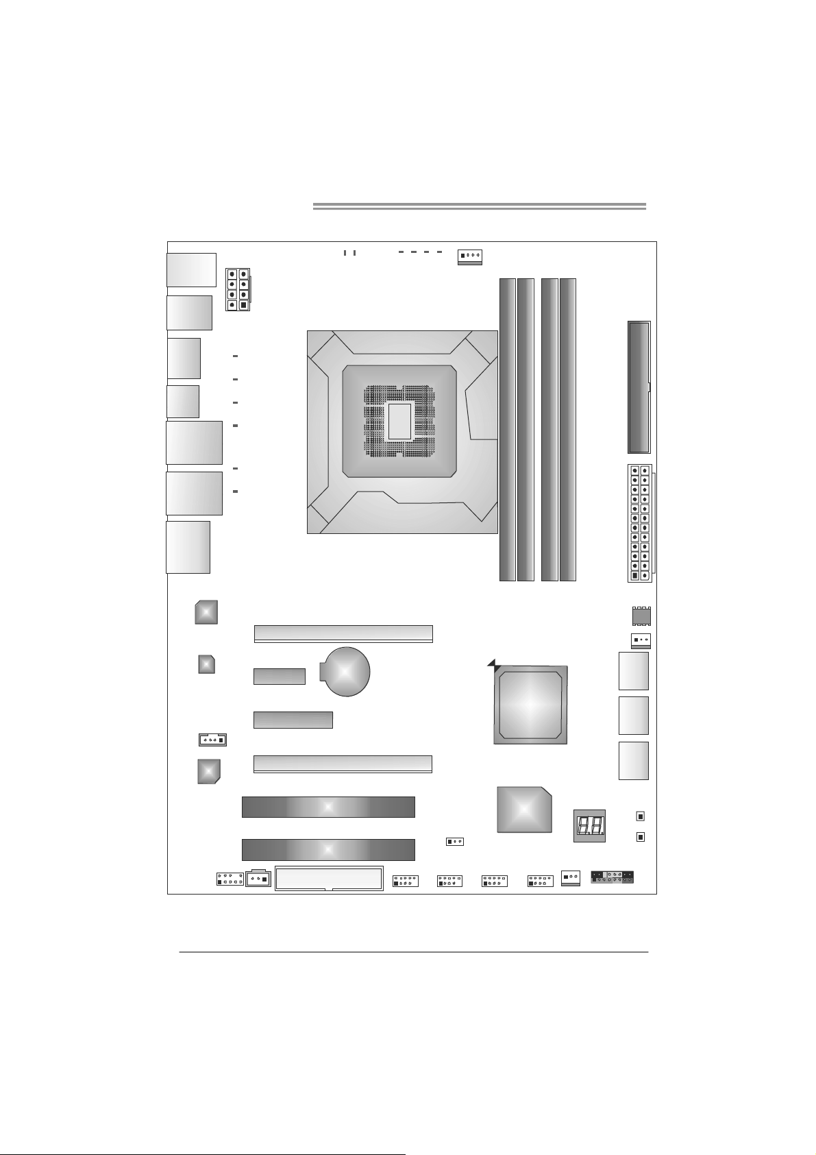
1.5 MOTHERBOARD LAYOUT
PH_LED2PH_LED1
USBKB1
PH4
PH3PH2PH1
CPU_ FAN1
1394_USB1
ESATAX1
JSPDIF1
RJ45USB1
RJ45USB2
AU DIO 2
LAN
LAN
ATX PWR2
PH_LED3
PH_LED4
PH_LED5
PH_LED6
PH_LED7
PH_LED8
PEX1_1
Socket 1156
PEX16_1
BAT1
CPU1
IDE1
DDR3_A2
DDR3_A1
DDR3_B2
DDR3_B1
ATX PWR1
BI O S
SYS_FAN2
SATA1
4
CDIN1
CODEC
AUDIO F1
Note: represents the 1■
JSPDIOUT1
PEX4_1
PEX16_2
PCI1
PCI2
FDD1
st
pin.
P55
Super
SATA2
SATA3
RSTS W1
I/O
JCMOS1
SYS_FAN1
F_JU SB3F_JUSB2F_JUSB1J1394_1
PWRSW1
PAN EL1
CHAPTER 2: HARDWARE INSTALLATION
TPower I55
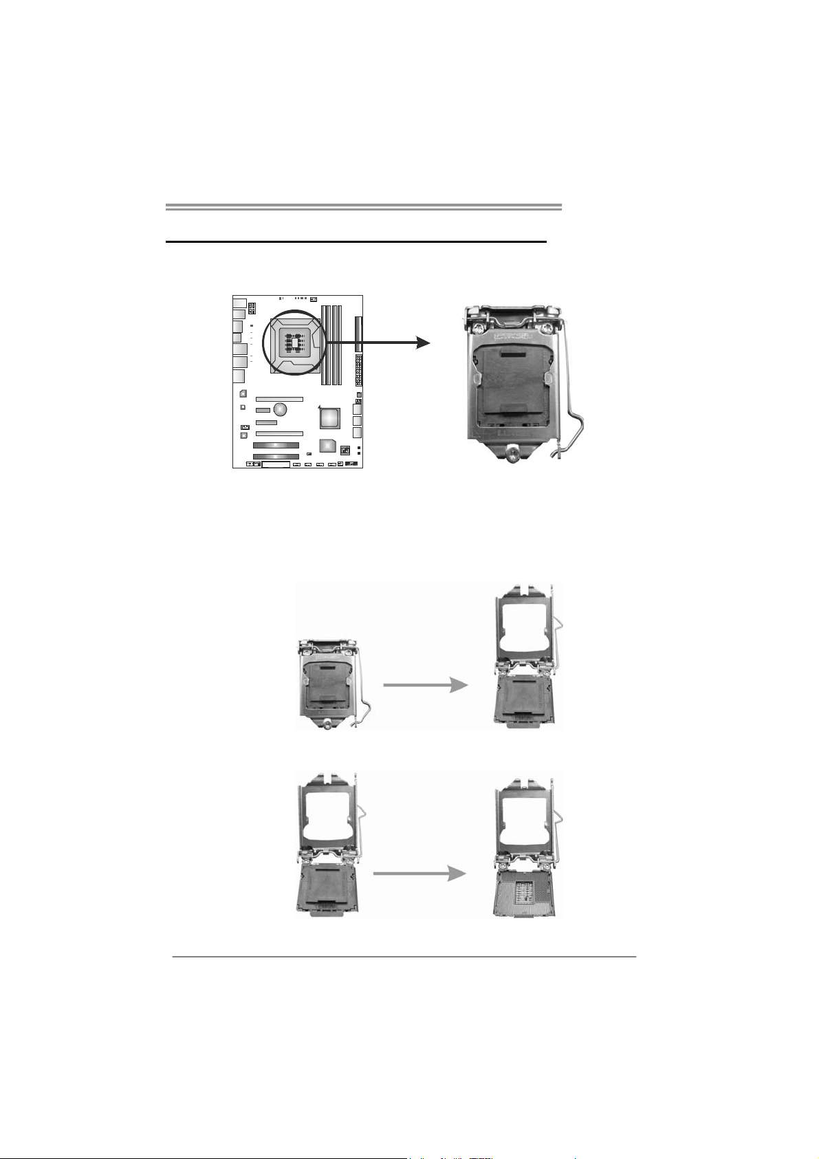
2.1 I
Remove Pin Cap before installation, and make good preservation
for future use. When the CPU is removed, cover the Pin Cap on the
empty socket to ensure pin legs won’t be damaged.
NSTALLING CENTRAL PROCESSING UNIT (CPU)
Step 1: Pull the socket locking lever out from the socket and then raise
the lever up.
Step 2: Remove the Pin Cap.
5
Motherboard Manual
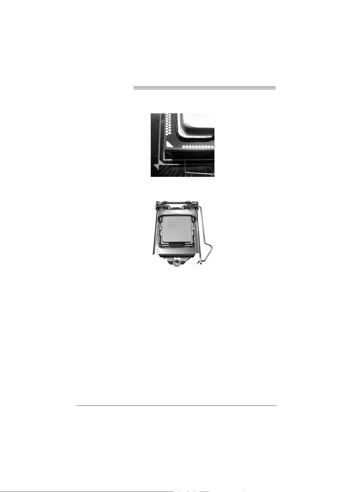
Step 3: Look for the triangular cut edge on socket, and the golden dot on
CPU should point forwards this triangular cut edge. The CPU will
fit only in the correct orientation.
Step 4: Hold the CPU down firmly, and then lower the lever to locked
position to complete the installation.
Step 5: Put the CPU Fan and heatsink assembly on the CPU and buckle it
on the retention frame. Connect the CPU FAN power cable into
the CPU_FAN1 to complete the installation.
6
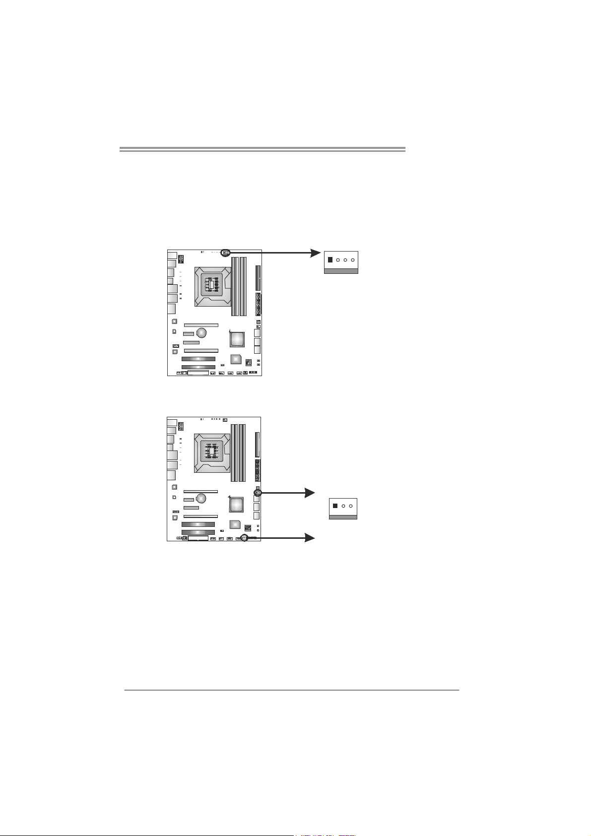
2.2 FAN HEADERS
These fan headers support cooling-fans built in the computer. The fan
cable and connector may be different according to the fan manufact urer.
Connect the fan cable to the connector while matching the black wire to
pin#1.
CPU_FAN1: CPU Fan Header
Pin
Assignment
14
SYS_FAN1/ SYS_FAN2: System Fan Headers
SYS_FAN2
1 Ground
2 +12V
3
FAN RPM r at e
sense
4 Smart Fan
Control
Pin
Assignment
1 Ground
2 +12V
3 FAN RPM rate
sense
TPower I55
13
SYS_FAN1
Note:
The SYS_FAN1/SYS_FAN2 support 3-pin head connectors, and the CPU_FAN1, 4-pin
head connector. When connecting with wires onto connectors, please note that the red
wire is the positive and should be connected to pin#2, and the black wire is Ground and
should be co nnected to GND.
7
Motherboard Manual
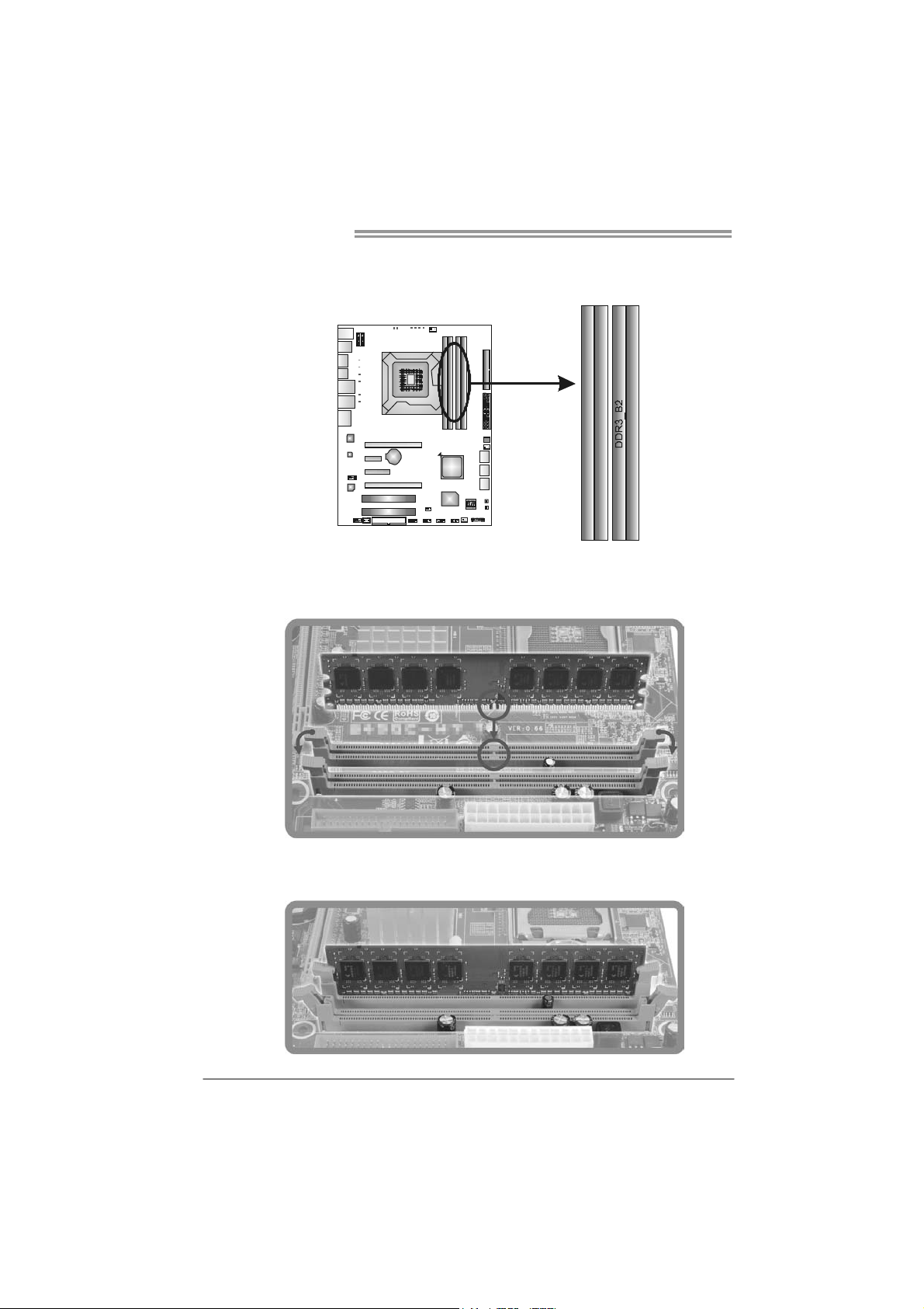
2.3 INSTALLING SYSTEM MEMORY
A. Memory Modules
DDR3_A2
DDR3_A1
1. Unlock a DIMM slot by pressing the retaining clips outward. Align a
DIMM on the slot such that the notch on the DIMM matches the
break on the Slot.
DDR3_B1
2. Insert the DIMM vertically and firmly into the slot until the retaining
chip snap back in place and the DIMM is properly seated.
8
B. Memory Capacity
DIMM Socket
Location
DDR3_A1 256MB/512MB/1GB/2GB / 4GB
DDR3 Module
TPower I55
Total Memory Size
DDR3_A2 256MB/512MB/1GB/2GB / 4GB
DDR3_B1 256MB/512MB/1GB/2GB / 4GB
DDR3_B2 256MB/512MB/1GB/2GB / 4GB
Max is 16GB.
C. Dual Channel Memory installation
Please refer to the following requirements to activate Dual Channel
function:
Install memory module of the same density in pairs, shown in the table.
Dual Channel Status
Enabled O O X X
Enabled O O O O
(O means memory installed, X means memory not installed.)
The DRAM bus width of the memory module must be the same (x8 or
x16)
Note:
Memory module must be installed in DDR3-A1 or DDR3-B1 to boot the
system.
DDR3_A1 DDR3_B1 DDR3_A2 DDR3_B2
9
Motherboard Manual
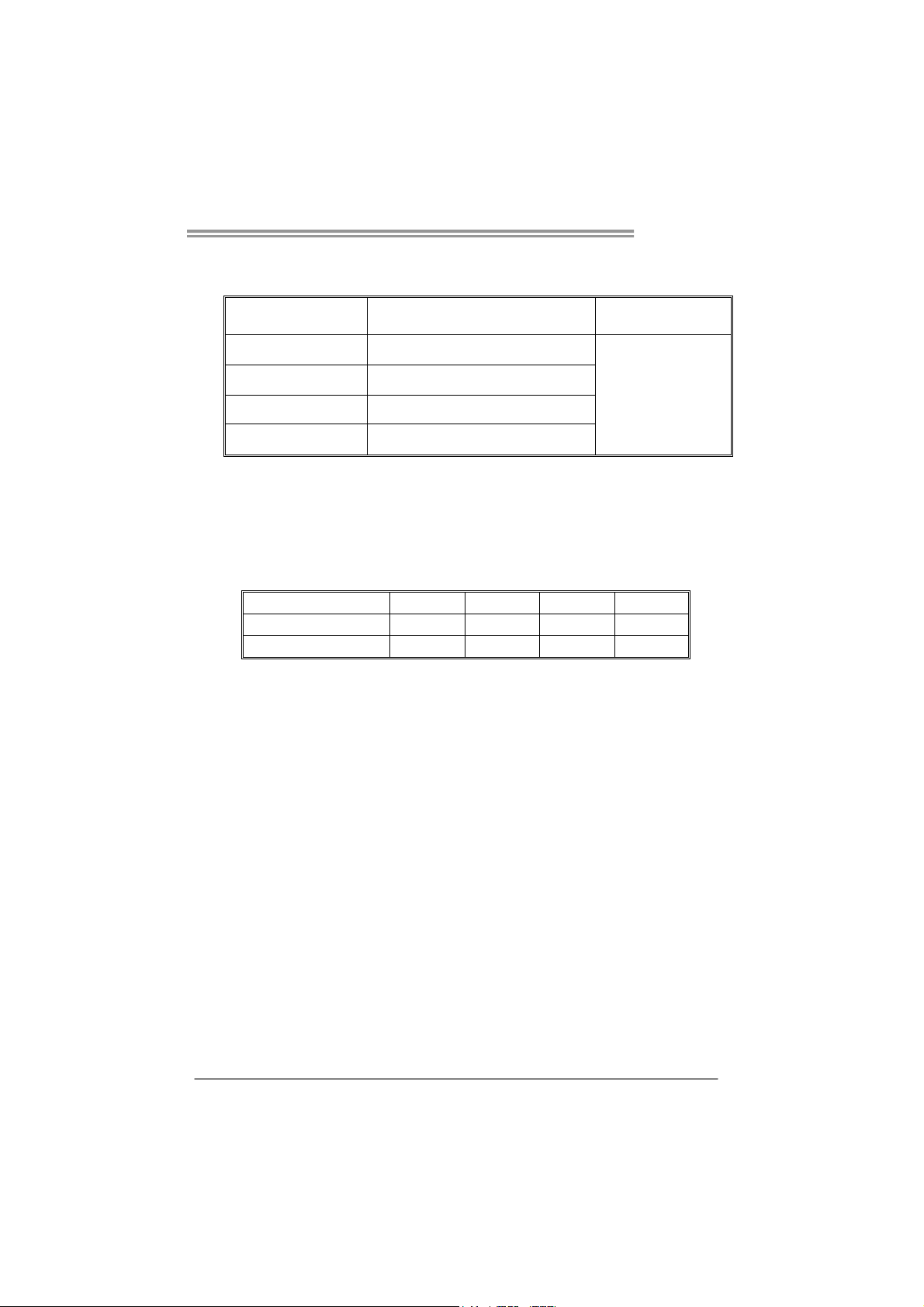
2.4 CONNECTORS AND SLOTS
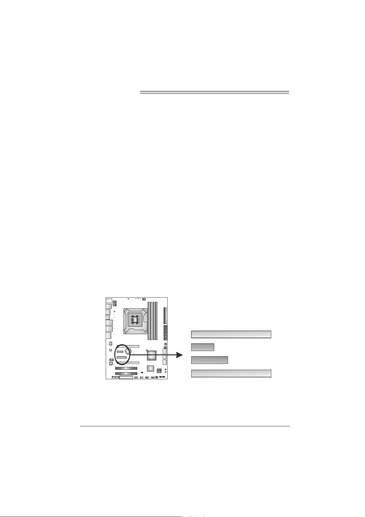
FDD1: Floppy Disk Connector
The motherboard provides a standard floppy disk connector that supports 360K,
720K, 1.2M, 1.44M and 2.88M floppy disk types. This connector supports the
provided floppy drive ribbon cables.
33 1
34
2
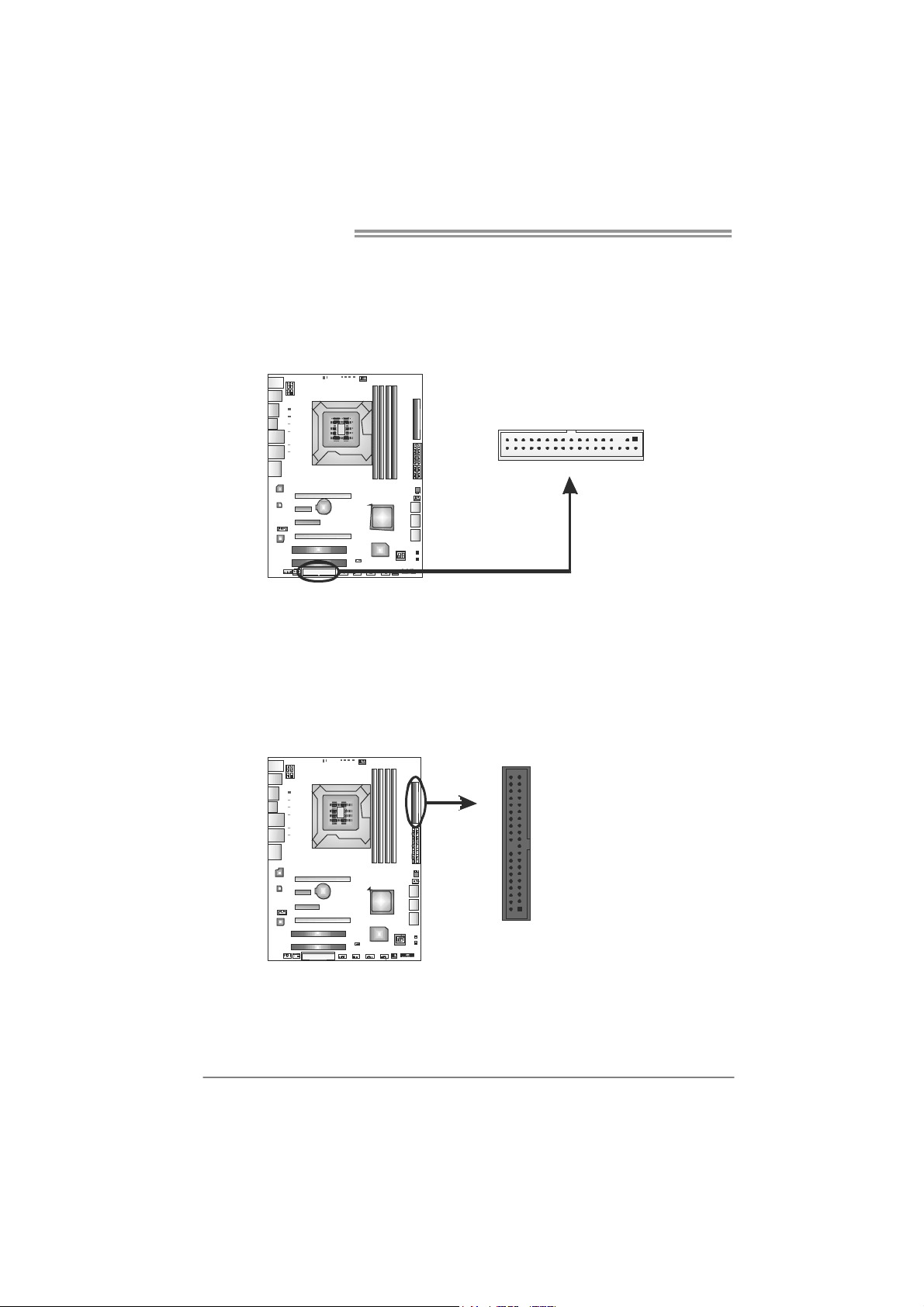
IDE1: IDE/ATAPI Connector
The motherboard has a 32-bit Enhanced PCI IDE Controller that provides PIO
Mode 0~4, Bus Master, and Ultra DMA 33/66/100/133 functionality.
The IDE connector can connect a master and a slave drive, so you can connect
up to two devices.
40 39
12
10
TPower I55
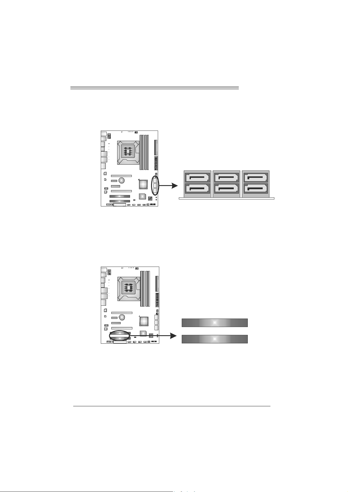
SATA1~SATA3: Serial ATA Connectors
The motherboard has a PCI to SATA Controller with 6 channels SATA interface,
it satisfies the SATA 2.0 spec and with transfer rate of 3.0Gb/s.
SATA3 SA TA2 SATA1
PCI1/PCI2: Peripheral Component Interconnect Slots
This motherboard is equipped with 2 standard PCI slots. PCI stands for
Peripheral Component Interconnect, and it is a bus standard for expansion
cards. This PCI slot is designated as 32 bits.
PCI1
PCI2
11
Motherboard Manual
PEX16_1: PCI-Express Gen2 x16 (x16/CrossFireX x8, SLI x8 Speed) Slot
- PCI-Express 2.0 compliant.
- Maximum theoretical realized bandwidth of 8GB/s (4GB/s CrossFireX/SLI)
simultaneously per direction, for an aggregate of 16GB/s(8GB/s
CrossFireX/SLI) totally.
- PEX16_1 & PEX16_2 slots are reserved for graphic or video cards. The
design of this motherboard supports dual PCI-Express graphics cards using
CrossFireX/SLI technology with multiple displays. When CrossFireX/SLI is
activated, these slots run with x8 speed.
PEX16_2: PCI-Express Gen2 x8 (x8/CrossFireX x8, SLI x8 Speed) Slot
- PCI-Express 2.0 compliant.
- Maximum theoretical realized bandwidth of 4GB/s (4GB/s CrossFireX/SLI)
simultaneously per direction, for an aggregate of 8GB/s(8GB/s
CrossFireX/SLI) totally.
PEX4_1: PCI-Express Gen2 x4 Slot
- PCI-Express 2.0 compliant.
- Maximum theoretical realized bandwidth of 2GB/s simultaneously per
direction, for an aggregate of 4GB/s totally.
PEX1_1: PCI-Express Gen2 x1 Slot
- PCI-Express 2.0 compliant.
- Data transfer bandwidth up to 500MB/s per direction; 1GB/s in total.
- PCI-Express supports a raw bit-rate of 2.5Gb/s on the data pins.
- 2X bandwidth over the traditional PCI architecture.
12
PEX16_1
PEX1_1
PEX4_1
PEX16_2
TPower I55
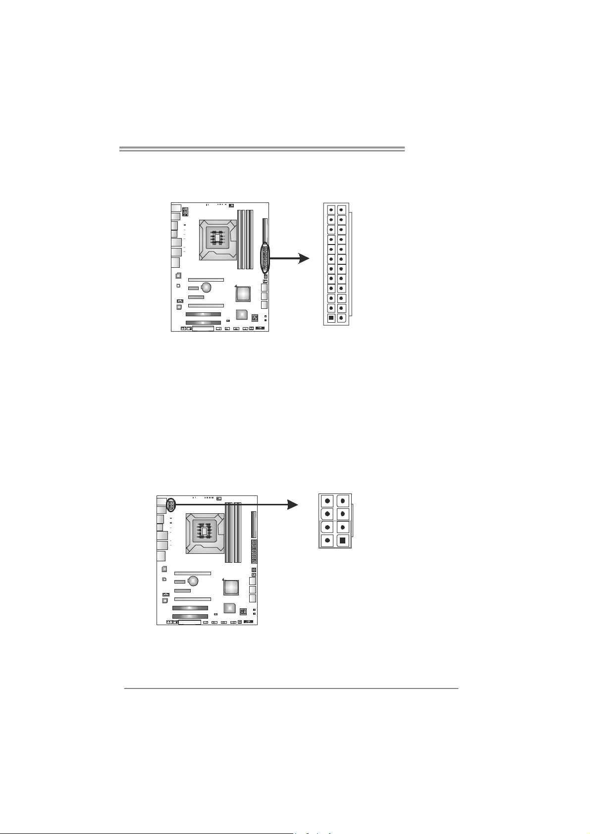
ATXP W R1: ATX Power Source Connector
This connector allows user to connect 24-pin power connector on the ATX
power supply.
12
1
Pin Assignment Pin Assignment
13 +3.3V 1 +3.3V
14 -12V 2 +3.3V
15 Ground 3 Ground
16 PS_ON 4 +5V
17 Ground 5 Ground
18 Ground 6 +5V
19 Ground 7 Ground
20 NC 8 PW_OK
21 +5V 9 Standby Voltage+5V
22 +5V 10 +12V
23 +5V 11 +12V
24 Ground 12 +3.3V
ATXP W R2: ATX Power Source Connector
This connector provides +12V to CPU power circuit.
8
24
13
45
Pin Assignment
1 +12V
2 +12V
3 +12V
1
4 +12V
5 Ground
6 Ground
7 Ground
8 Ground
Note:
Before power on the system, please make sure that both ATXPWR1 and ATXPWR2
connectors have been plugged-in.
If the CPU power plug is 4-pin, please plug it into Pin 1-2-5-6 of ATXPWR2.
13
Motherboard Manual
CHAPTER 3: HEADERS & JUMPERS SETUP
3.1 H
OW TO SETUP JUMPERS
The illustration shows how to set up jumpers. When the jumper cap is
placed on pins, the jumper is “close”, if not, that means the jumper is
“open”.
Pin opened Pin closed Pin1-2 closed
3.2 D
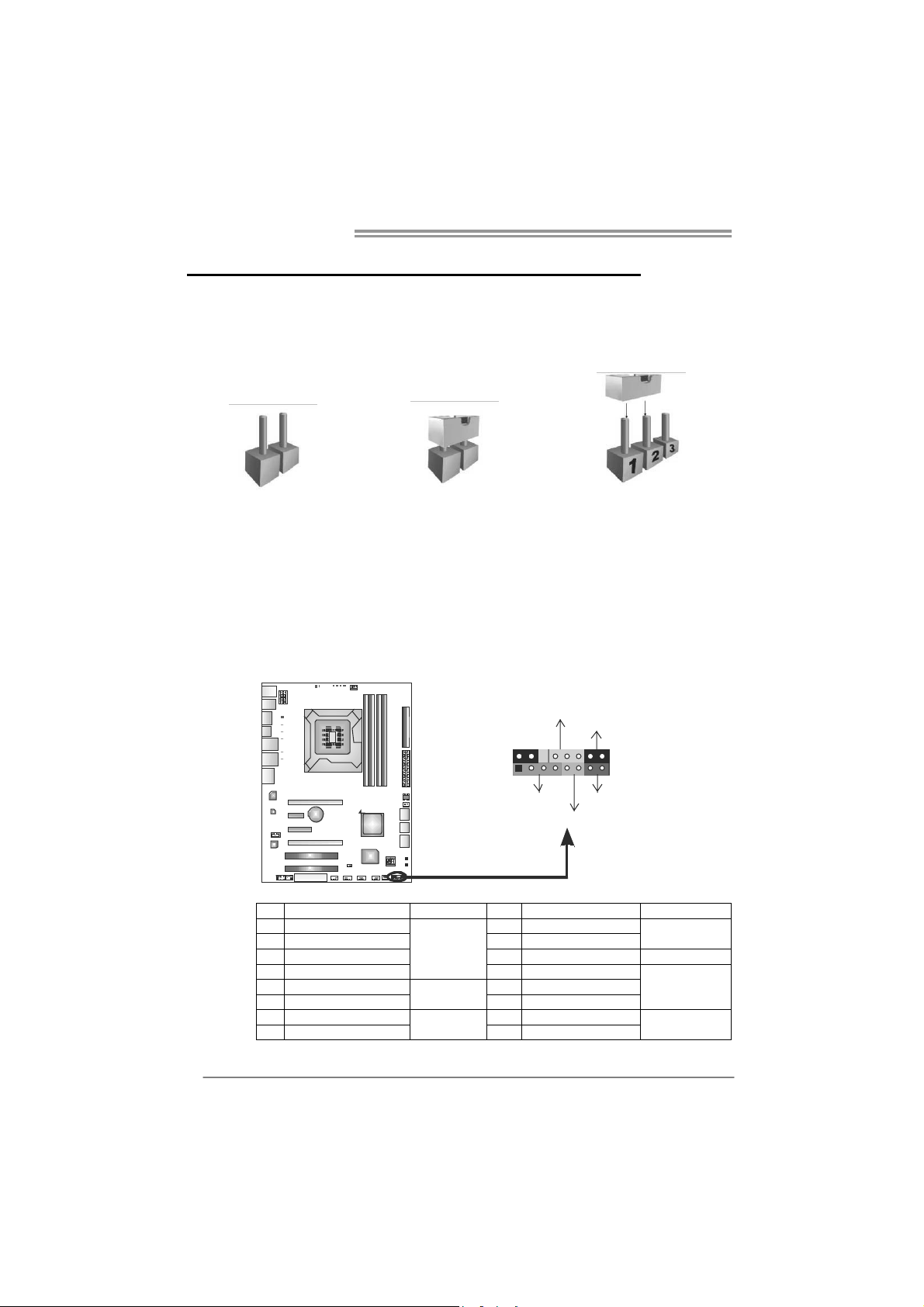
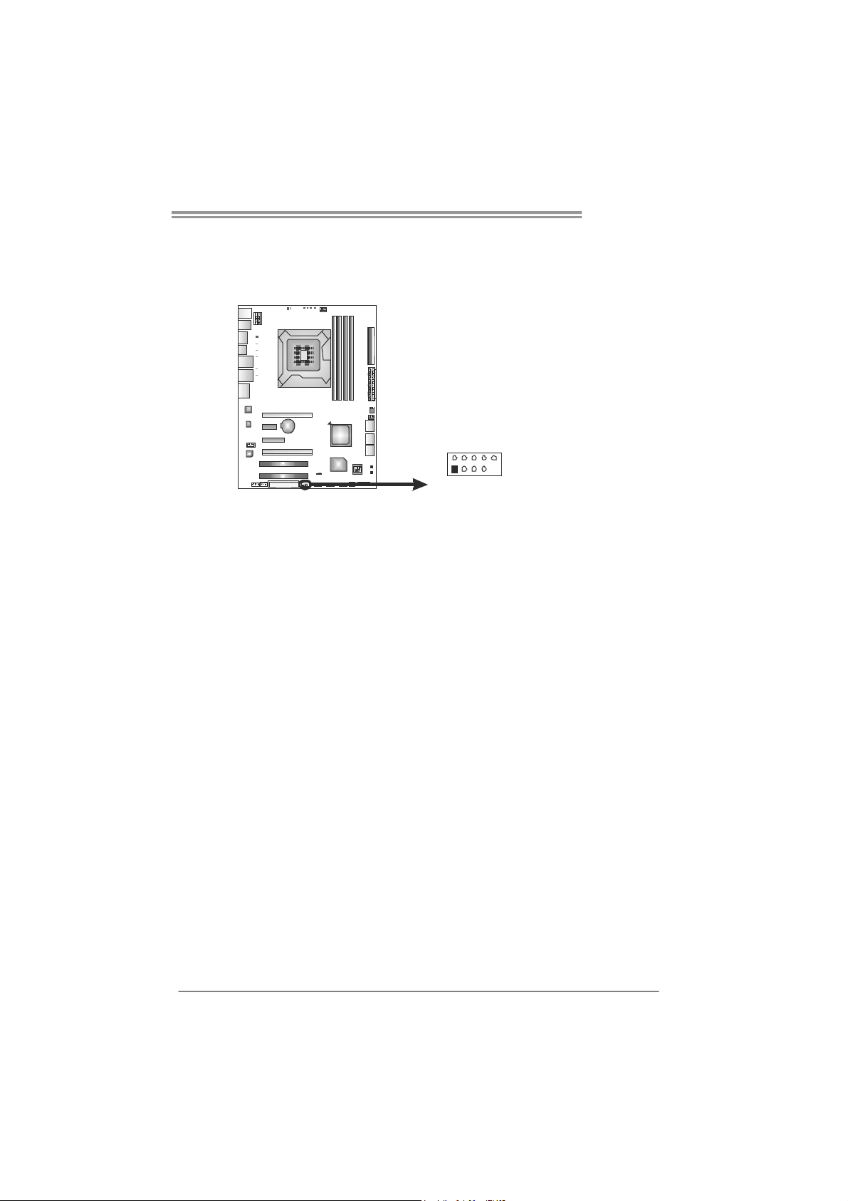
PANEL1: Front Panel Header
ETAIL SETTINGS
This 16-pin connector includes Power-on, Reset, HDD LED, Power LED, and
speaker connection. It allows user to connect the PC case’s front panel switch
functions.
PWR_LED
On/Off
-
SPK
++
+
HLED
-
16
8
RST
9
1
14
Pin Assignment Function Pin Assignment Function
1 +5V 9 N/A
2 N/A 10 N/A
3 N/ A 11 N/ A N/ A
4 Speaker
5 HDD LED (+) 13 Power LED (+)
6 HDD LED (-)
7 Ground 15 Power button
8 Reset control
Speaker
Connector
Hard drive
LED
Reset button
12 Power LED (+)
14 Power LED (-)
16 Ground
N/A
Power LED
Power-on button
TPower I55
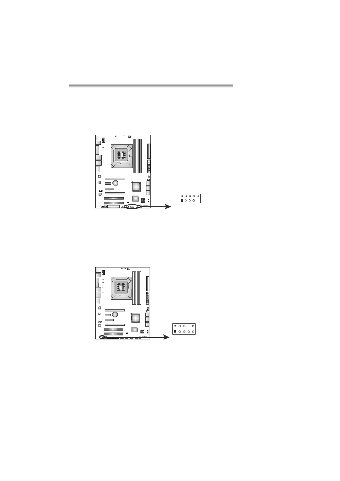
F_JUSB1 ~ F_JUSB3: Headers for USB 2.0 Ports at Front Panel
Theses headers allow user to connect additional USB cable on the PC front
panel. They also can be connected with internal USB devices, like USB card
reader.
Pin
Assignment
1 +5V (fused)
2 +5V (fused)
3 USB4 USB5 USB+
F_JUSB1 F_
F_JUSB2
2910
JUSB3
6 USB+
7 Ground
8 Ground
9 Key
10 NC
1
AUDIOF1: Front Panel Audio Header
This header allows user to connect the front audio output cable with the PC front
panel. This header allows only HD audio front panel connector; AC’97 connector
is not acceptable.
Pin
Assignment
1 Mic Left in
2 Ground
3 Mic Right in
4 GPIO
5 Right line in
6 Jack Sense
7 Front Sense
2
1
10
9
8 Key
9 Left line in
10 Jack Sense
15
Motherboard Manual
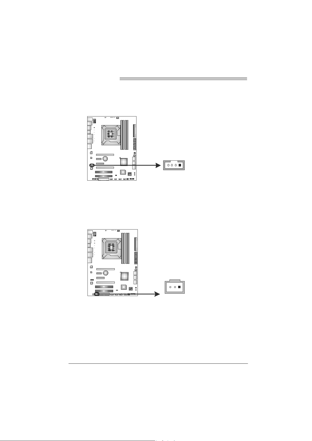
CDIN1: CD-ROM Audio-in Connector
This connector allows user to connect the audio source from the different
devices, like CD-ROM, DVD-ROM, PCI sound card, PCI TV turner card etc..
JSPDIOUT1: Digital Audio-out Connectors
JSPDIOUT1 is for connecting the PCI bracket SPDIF output.
41
Assignment
Pin
1 Left Channel Input
2 Ground
3 Ground
4 Right Channel Input
Pin
Assignment
1 +5V
2 SPDIF_OUT
3 Ground
16
31
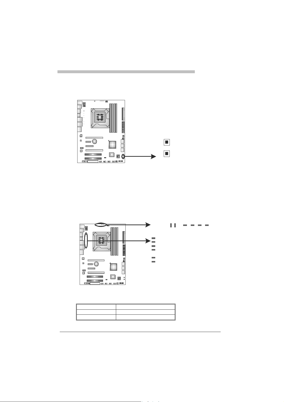
On-Board Buttons
There are 2 on-board buttons.
TPower I55
RSTSW1
PWRSW1
PWRSW1:
This is an on-board Power Switch button.
RSTSW1:
This is an on-board Reset button.
On-Board LED Indicators
There are 12 LED indicators on the motherboard showing 8+4 Phase CPU
Power.
PH_LED1
PH_LED2
PH_LED3
PH_LED4
PH_LED5
PH_LED6
PH_LED7
PH_LED8
PH1
PH1 ~ PH4: CPU VTT (uncore) Power Status Indicators
PH_LED1 ~ PH_LED8: CPU Power Phase Status Indicators
Please refer to the tables below for different messages:
LED Phase Indicator
ON Phase Active
OFF Phase Disable
PH3
PH2 PH4
17
Motherboard Manual
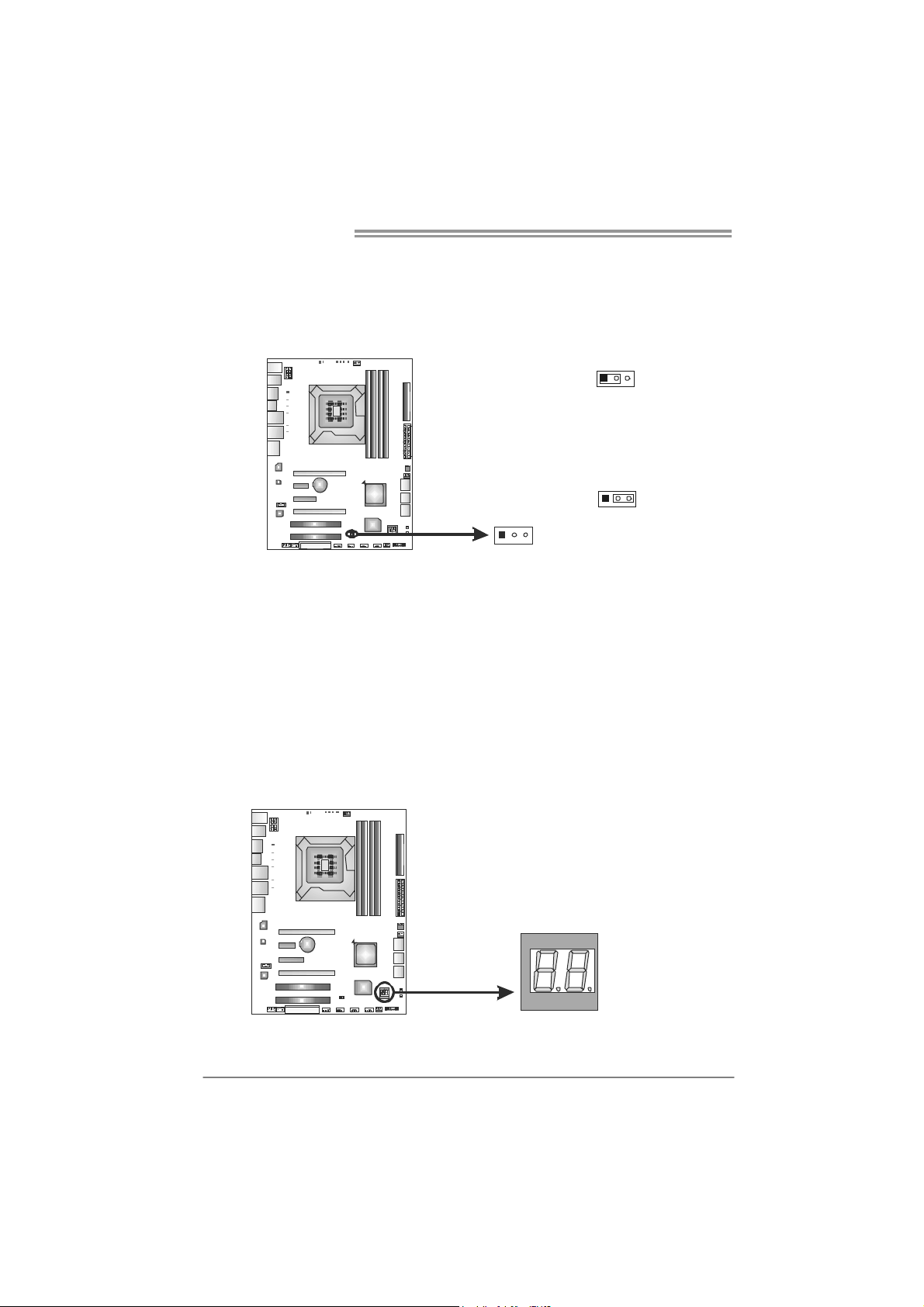
JCMOS1: Clear CMOS Header
Placing the jumper on pin2-3 allows user to restore the BIOS safe setting and
the CMOS data. Please carefully follow the procedures to avoid damaging the
motherboard.
※ Clear CMOS Procedures:
1. Remove AC power line.
2. Set the jumper to “Pin 2-3 close” .
3. Wait for five seconds.
4. Set the jumper to “Pin 1-2 close” .
5. Power on the AC.
6. Reset your desired password or clear the CMOS data.
13
13
Pin 1-2 Close:
Normal Operation (default).
13
Pin 2-3 Close:
Clear CMOS data.
BIOS POST Code
This indicator will show POST code while booting. Please refer to Chapter 6.4
for all the BIOS POST codes.
18
J1394_1: IEEE 1394 Header
This header allows user to connect IEEE 1394 device.
2910
TPower I55
Pin
Assignment
1 TPA1+
2 TPA13 GND
4 GND
5 TPB1+
6 TPB17 VCC
8 VCC
9 N/A
10 KEY
1
19
 Loading...