

Biostar TP75 Owner's Manual
TP75 Setup Manual
FCC Information and Copyright
This equipment has been tested and found to comply with the limits of a Class
B digital device, pursuant to Part 15 of the FCC Rules. These limits are designed
to provide reasonable protection against harmful interference in a residential
installation. This equipment ge nerates, uses, and can radiate radio frequency
energy and, if not i nstalled and used in accordance with the instructions, may
cause harmful interference to radio communications. There is no guarantee
that interference will not occur in a particular installation.
The vendor makes no representations or warranties with respect to the
contents here and specially disclaims any implied warranties of merchantability
or fitness for any purpose. Further the vendor reserves the right to revise this
publication and to make changes to the contents here without obligation to
notify any party beforehand.
Duplication of this publication, in part or in whole, is not allowed without first
obtaining the vendor’s approval in writing.
The content of this user’s manual is subject to be changed without notice and
we will not be responsible for any mistakes found in this user’s manual. All the
brand and product names are trademarks of their respective companies.
Dichiar azione di conf orm ità
sintetica
Ai sensi dell’art. 2 comma 3 del D.M.
275 del 30/10/2002
Si dichiara che questo prodotto è
conforme alle normative vigenti e
soddisfa i requisiti essenziali richiesti
dalle direttive
2004/108/CE, 2006/95/CE e
1999/05/CE
quando ad esso applicabili
Short De cla ra tion of conf ormity
We declare this product is complying
with the laws in force and meeting all
the essential requirements as specified
by the directives
2004/108/CE, 2006/95/CE and
1999/05/CE
whenever these laws may be applied

Table of Contents
Chapter 1: Introduction ........................................ 1
1.1 Before You Start......................................................................................... 1
1.2 Package Checklist..................................................................................... 1
1.3 Motherboard Features.............................................................................. 2
1.4 Rear Panel Connectors.............................................................................. 3
1.5 Motherboard Layout................................................................................. 4
Chapter 2: Hardware Installation .......................... 5
2.1 Installing Central Processing Unit (CPU) ............................................... 5
2.2 FAN Headers.............................................................................................. 7
2.3 Installing System Memory ........................................................................ 8
2.4 Connectors and Slots................................................................................ 10
Chapter 3: Headers & Jumpers Setup .................. 14
3.1 How to Setup Jumpers............................................................................. 14
3.2 Detail Settings .......................................................................................... 14
Chapter 4: Useful Help ........................................ 19
4.1 Driver Installation Note.......................................................................... 19
4.2 Software .................................................................................................... 20
4.3 BIOS Update............................................................................................. 22
4.4 Inte l® Small Business Advantage.......................................................... 27
4.5 Extra Information.................................................................................... 29
4.6 AMI BIOS Beep Code............................................................................... 30
4.7 Troubleshooting....................................................................................... 31
Appendix: SPEC In Other Languages ................... 32
German.................................................................................................................. 32
French .................................................................................................................... 34
Italian..................................................................................................................... 36
Spanish ................................................................................................................... 38
Portuguese ............................................................................................................ 40
Polish...................................................................................................................... 42
Russian ................................................................................................................... 44
Arabic..................................................................................................................... 46
Japanese ................................................................................................................ 48
CHAPTER 1: INTRODUCTION
TP75
1.1 B
EFORE YOU START
Thank you for choosing our product. Before you start installing the
motherboard, please make sure you follow the instructions below:
Prepare a dry and stable working environment with
sufficient lighting.
Always disconnect the computer from power outlet
before operation.
Before you take the motherboard out from anti-static
bag, ground yourself properly by touching any safely
grounded appliance, or use grounded wrist strap to
remove the static charge.
Avoid touching the components on motherboard or the
rear side of the board unless necessary. Hold the board
on the edge, do not try to bend or flex the board.
Do not leave any unfastened small parts inside the
case after installation. Loose parts will cause short
circuits which may damage the equipment.
Keep the computer from dangerous area, such as heat
source, humid air and water.
The operating temperatures of the computer should be
0 to 45 degrees Celsius.
1.2 PACKAGE CHECKLIST
Serial ATA Cable x2
Rear I/O Panel for ATX Case x1
User’s Manual x1
Fully Setup Driver DVD x1
Note: The package contents may be different due to area or your motherboard version.
1
Motherboard Manual
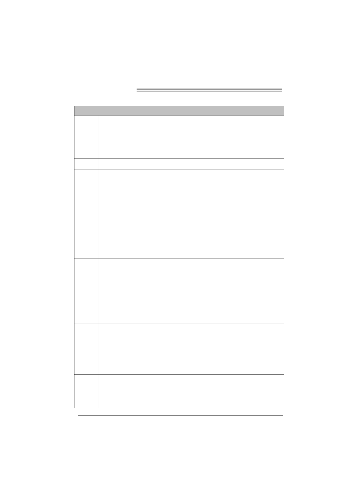
1.3 MOTHERBOARD FEATURES
SPEC
CPU
Chipset
Super I/O
Main
Memory
SATA 2 & 3
LAN
Socket 1155
Int e l Co re i7 / i5 / i3 / Pent iu m / Ce le ro n
processo r (TDP: 95W)
B75
IT8728F-EX
Prov ides the most commonly used legac y
Super I/O functionality.
Low Pin Count Interface
DDR3 DIMM Slots x 2
Max Memory Capacity 16GB
Each DIMM supports 512MB/
1GB/2GB/4GB/8GB DDR3
Integrated Serial ATA Controller
Realtek RTL 8111F
Supports Execute D isab le Bit / Enh anced Inte l
SpeedStep® / Intel Architecture-64 / Ex tended
Memory 64 Technology / V irtualization Technology /
Hyp er Thread ing
En v ironm ent C o ntro l in iti at i ves ,
Hardware Monitor Controller
Fan Sp eed Contro ller
ITE's "S mart Guardian " funct ion
Dual Channel Mode DDR 3 me mo ry modu le
Supports DDR3 1066 / 1333
Supports DDR3 1600 (depending on C PU)
Register ed DIMM and ECC D IMM is not supported
Data transfer rates up to 3.0 Gb/s / 6.0 Gb/s.
SATA Version 2.0 / 3.0 specification compliant
10 / 100 Mb/s / 1Gb/s auto negot iation
Half / Full duplex capability
Sound
Codec
USB3.0
Slots
2
ALC662
5.1 channels audio out
High Definition Audio, Biostar Hi-Fi
B75 Data transfer rates up to 600 MB/s
PCI slot x2 Supports PCI expansion cards
PCI Express Gen3 x 16 slot x1 Supports PCI-E Gen3 x16 expansion card
PCI Express Gen2 x 16 slot(x4) x1 Supports PCI-E Gen2 x16 expansion card
PCI Express Gen2 x 1 slot x2 Supports PCI-E Gen2 x1 expansion cards
SATA3 Connector x1 Each conne ctor suppo rts 1 SATA3 devices
SATA2 Connector x5 Each conne ctor suppo rts 1 SATA2 devices
Front Panel Connector x1 Supports front panel facilit ies
On Board
Connectors
TP75
SPEC
Front Audio Connector x1 Supports front panel audio function
CPU Fan Header x1 CPU Fan power supply (with Smart Fan funct ion)
System Fan Header x1 System Fan Power supply
Clear CMOS Head er x1 Restore CMOS dat a to factory def au lt
USB2.0 Connector x2 Each conne ctor s upports 2 front panel USB2.0 po rts
USB3.0 Connector x1 Each conne ctor s upports 2 front panel USB3.0 po rts
Printer Port Connector x1 Each connector supports 1 Printer port
S/PDIF out Connector x1 Supports digital audio out function
Power Connector (24pin) x1 Connects to Power supp ly
Power Connector (4pin) x1 Connects to Power supply
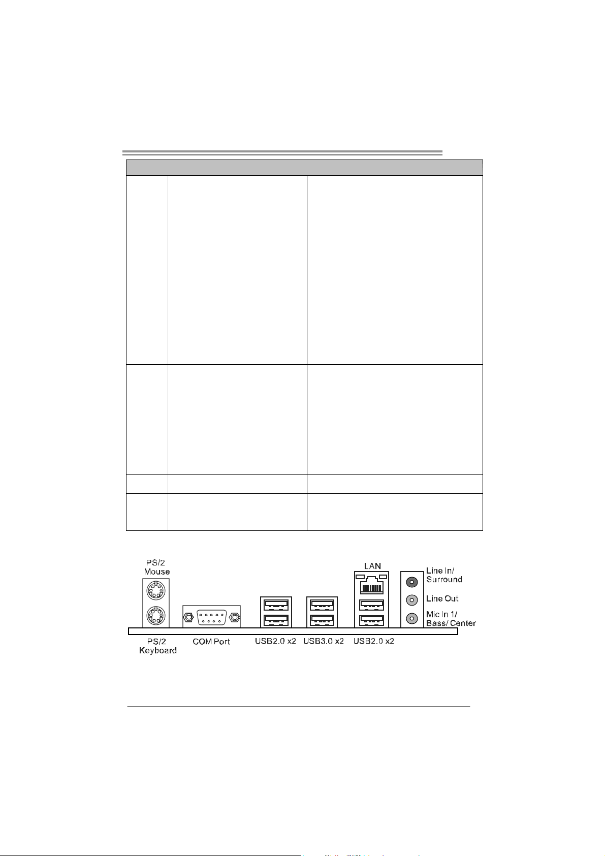
Connects to PS/2 Keyboard/ Mouse
Connects to RS-232 Port
Connect to RJ-45 Ethernet cable
Connect to USB2.0 devices
Connect to USB3.0 devices
Provide Audio-In/Out and Mic. connection
Biostar reserves the right to add or remove support for
any OS with or without notice
Back Panel
I/O
Board Size
OS Support
PS/2 K eyboard/ Mouse x1
COM port x1
LAN port x1
USB2.0 Port x4
USB3.0 Port x2
Audio Jack x3
210 (W) x 305 (L) mm ATX
Windows XP / Vista / 7
1.4 REAR PANEL CONNECTORS
Note: USB3.0 ports (only supported by Windows 7) are backward compatible with
USB2.0/USB1.X devices.
3
Motherboard Manual
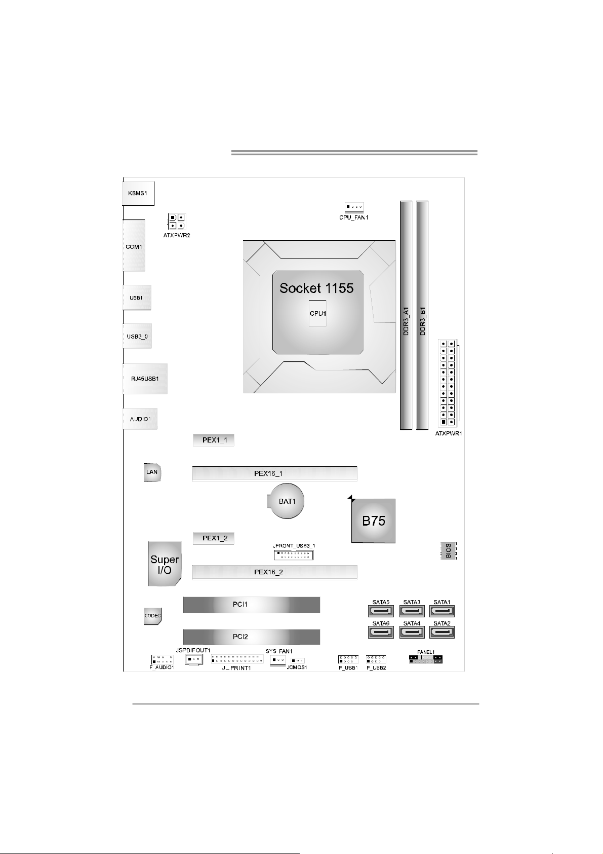
1.5 MOTHERBOARD LAYOUT
Note: ■ represents the 1st pin.
4
CHAPTER 2: HARDWARE INSTALLATION
TP75
2.1 I
NSTALLING CENTRAL PROCESSING UNIT (CPU)
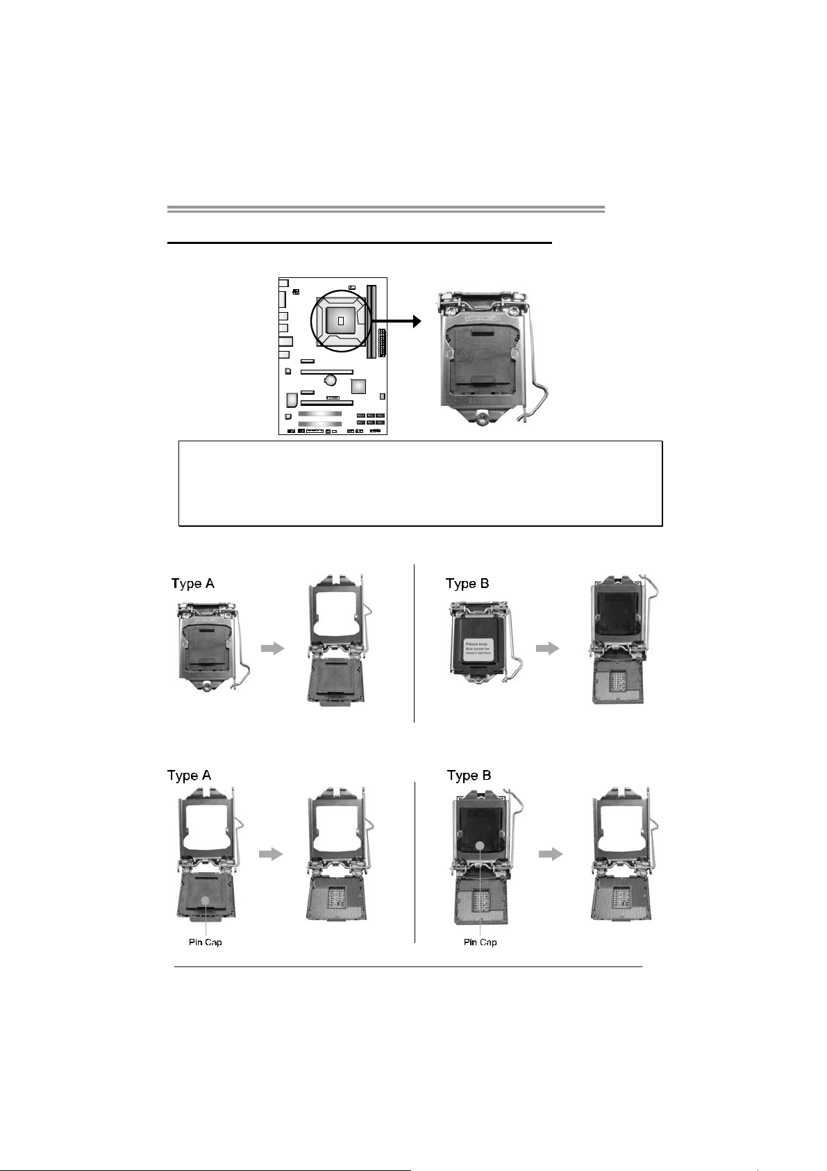
Notice:
1. Remove Pin Cap before installation, and make good preservation for future use. When the
CPU is removed, cover the Pin Cap on the empty socket to ensure pin legs won’t be
damaged.
2. The motherboard might equip with two different types of pin cap. Please refer below
instruction to remove the pin cap.
Step 1: Pull the socket locking lever out from the socket and then raise
the lever up.
Step 2: Remove the Pin Cap.
5
Motherboard Manual
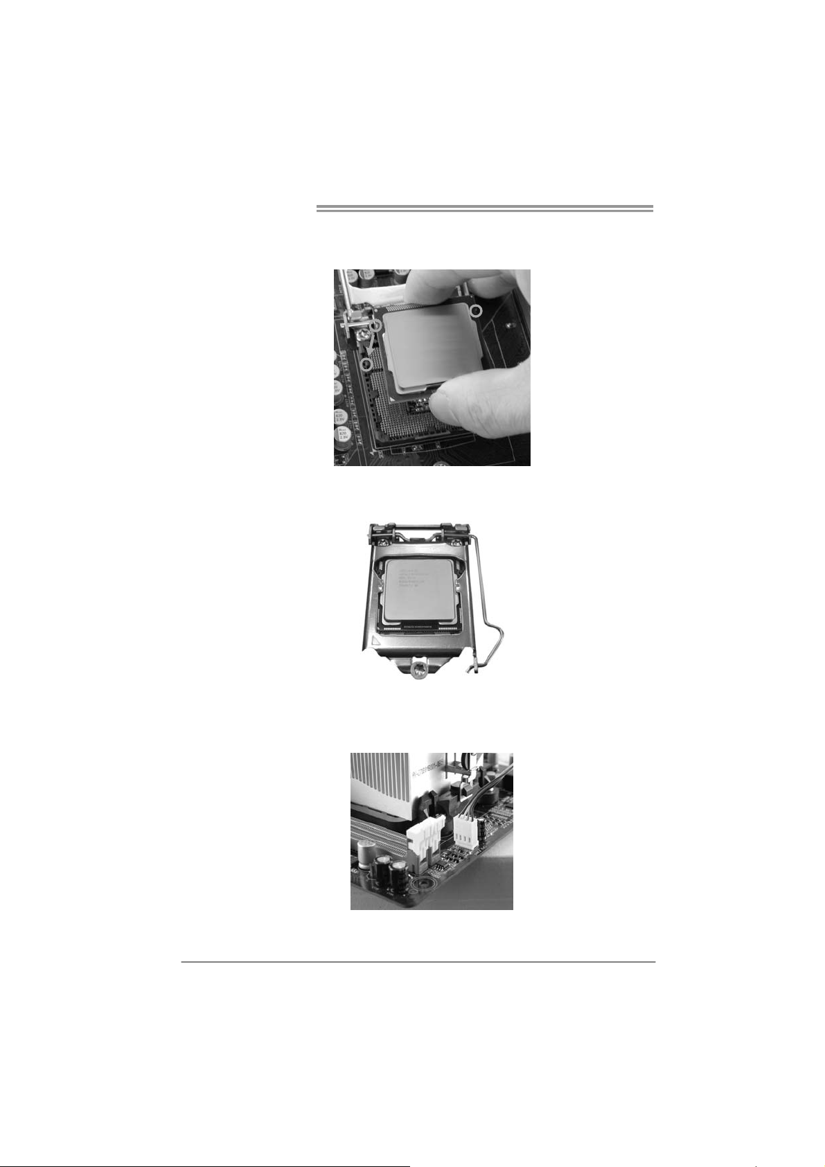
Step 3: Hold processor with your thumb and index fingers, oriented as
shown. Align the notches with the socket. Lower the processor
straight down without tilting or sliding the processor in the socket.
Step 4: Hold the CPU down firmly, and then lower the lever to locked
position to complete the installation.
Step 5: Put the CPU Fan and heatsink assembly on the CPU and buckle it
on the retention frame. Connect the CPU FAN power cable into
the CPU_FAN1 to complete the installation.
6
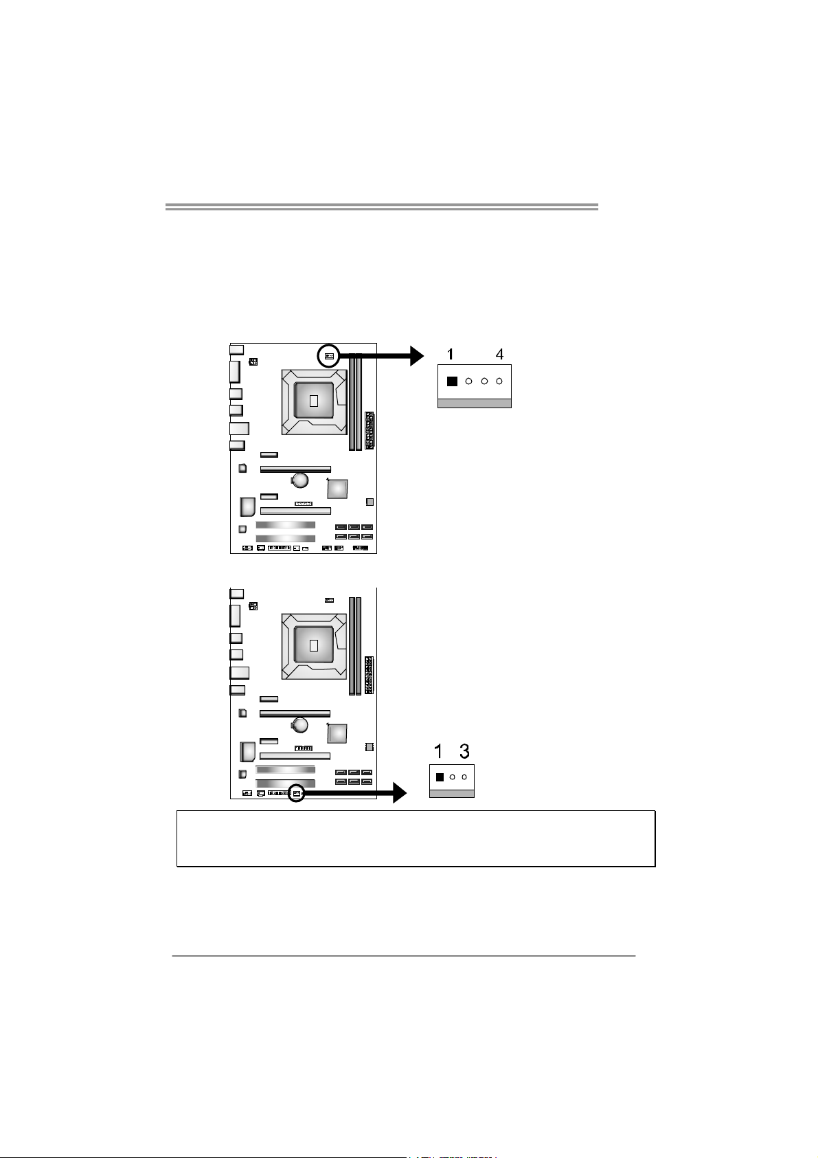
2.2 FAN HEADERS
These fan headers support cooling-fans built in the computer. The fan
cable and connector may be different according to the fan manufacturer.
Connect the fan cable to the connector while matching the black wire to
pin#1.
CPU_FAN1: CPU Fan Header
Pin Assignment
1 Ground
2 +12V
3 FAN RPM rate sense
4 Smart Fan Control
SYS_FAN1: System Fan Header
TP75
Pin Assignment
1 Ground
2 +12V
3 FAN RPM rate sense
Note:
The SYS_FAN1 supports 3-pin head connectors; the CPU_FAN1 supports 4-pin head connector.
When connecting with wires onto connectors, please note that the red wire is the positive and
should be co nnected to pin#2, and the black wire is Ground and should be connected to GND.
7
Motherboard Manual
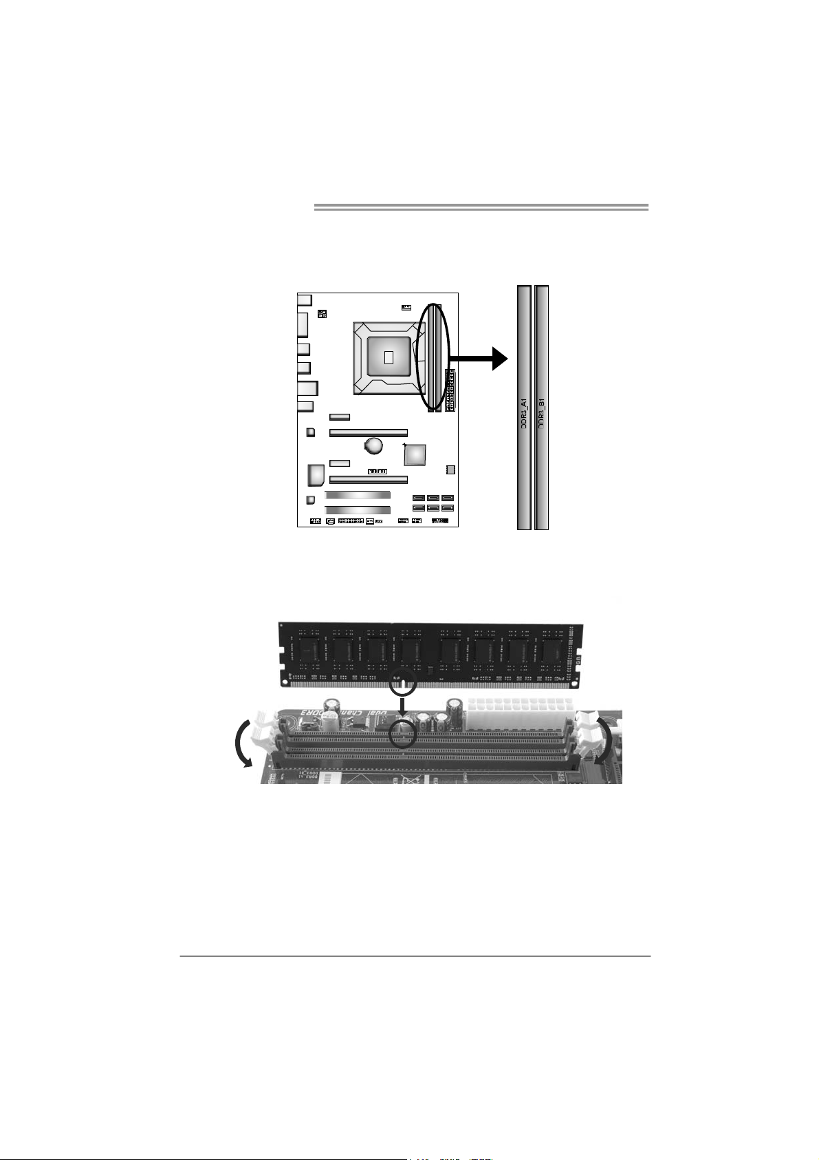
2.3 INSTALLING SYSTEM MEMORY
A. Memory Modules
1. Unlock a DIMM slot by pressing the retaining clips outward. Align a
DIMM on the slot such that the notch on the DIMM matches the
break on the Slot.
8
TP75
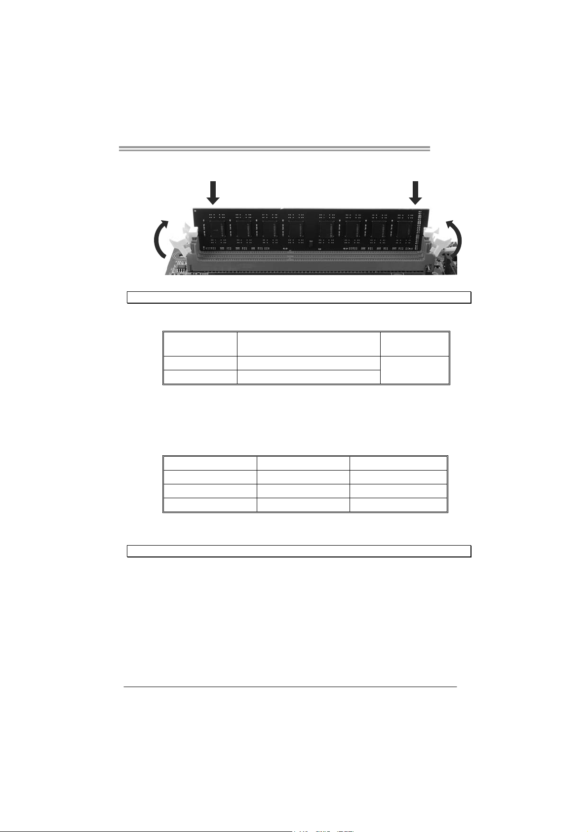
2. Insert the DIMM vertically and firmly into the slot until the retaining
chip snap back in place and the DIMM is properly seated.
Note: If the DIMM does not go in smoothly, do not force it. Pull it all the way out and try again.
B. Memory Capacity
DIMM Socket
Location
DDR3_A1 512MB/1GB/2GB/4GB/8GB
DDR3_B1 512MB/1GB/2GB/4GB/8GB
DDR3 Module
C. Dual Channel Memory Installation
Please refer to the following requirements to activate Dual Channel function:
Install memory module of the same density in pairs, shown in the table.
Dual Channel Status
Disabled O X
Disabled X O
Enabled O O
(O means memory installed; X, not installed.)
Note: The DRAM bus width of the memory module must be the same (x8 or x16)
DDR3_A1
DDR3_B1
Total Me m ory
Size
Max is 16GB.
9
Motherboard Manual
2.4 CONNECTORS AND SLOTS
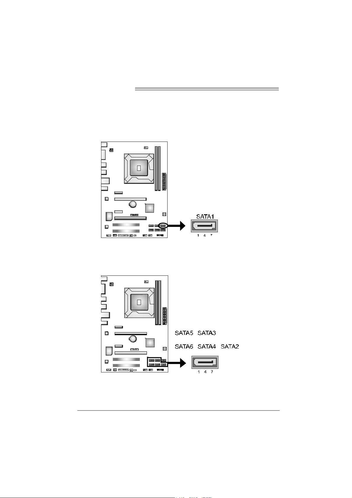
SATA1: Serial ATA3.0 Connectors
The connector connect to SATA hard disk drives via SATA cables.
Those satisfy the SATA 3.0 spec and with transfer rate of 6.0Gb/s.
SATA2 ~ 6: Serial ATA2.0 Connectors
These connectors connect to SATA hard disk drives via SATA cables.
Those satisfy the SATA 2.0 spec and with transfer rate of 3.0Gb/s.
Pin
Assignment
1 Ground
2 TX+
3 TX4 Ground
5 RX6 RX+
7 Ground
10
Pin
Assignment
1 Ground
2 TX+
3 TX4 Ground
5 RX6 RX+
7 Ground
TP75
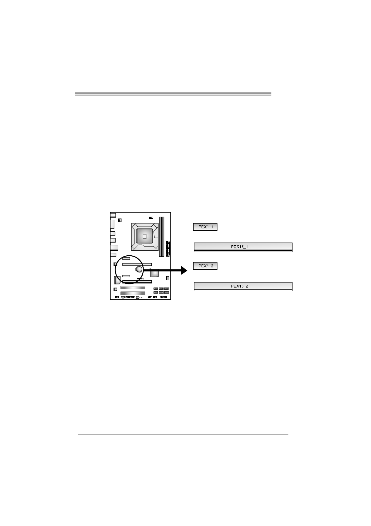
PEX16_1: PCI-Express Gen3 x16 (x16) Slot
- PCI-Express 3.0 compliant.
- Maximum theoretical realized bandwidth of 16GB/s simultaneously per
direction, for an aggregate of 32GB/s totally.
- PCI-E 3.0 is supported by Core i7-3xxx / i5-3xxx CPU.
PEX16_2: PCI-Express Gen2 x4 Slot
- PCI-Express 2.0 compliant.
- Maximum theoretical realized bandwidth of 2GB/s simultaneously per
direction, for an aggregate of 4GB/s totally.
PEX1_1/PEX1_2: PCI-Express Gen2 x1 Slot
- PCI-Express 2.0 compliant.
- Data transfer bandwidth up to 500MB/s per direction; 1GB/s in total.
11

Motherboard Manual
PCI1/PCI2: Peripheral Component Interconnect Slots
This motherboard is equipped with 2 standard PCI slots. PCI stands for
Peripheral Component Interconnect, and it is a bus standard for expansion
cards. This PCI slot is designated as 32 bits.
ATXP W R2: AT X P ower Source Connector
This connector provides +12V to CPU power circuit.
Pin Assignment
1 +12V
2 +12V
3 Ground
4 Ground
12
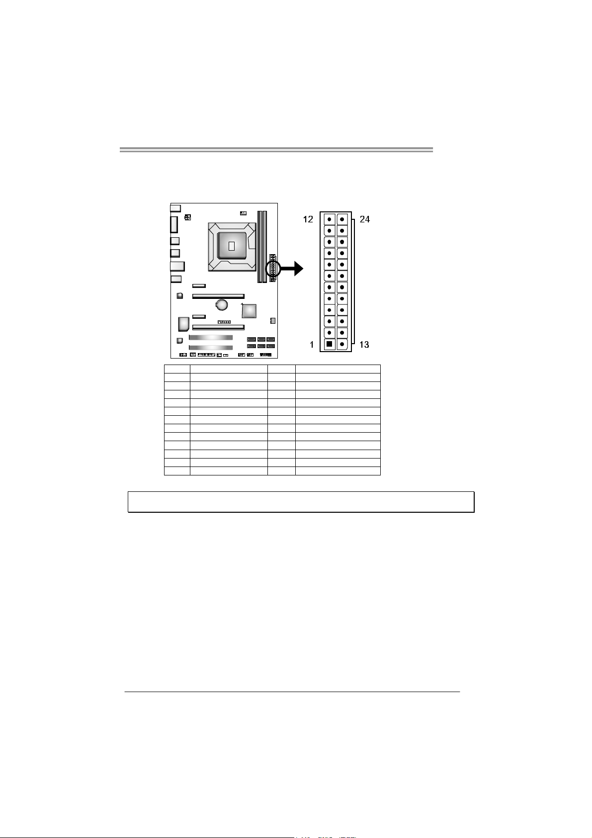
ATXP W R1: AT X P ower Source Connector
This connector allows user to connect 24-pin power connector on the ATX
power supply.
Pin Assignment Pin Assignment
13 +3.3V 1 +3.3V
14 -12V 2 +3.3V
15 Ground 3 Ground
16 PS_ON 4 +5V
17 Ground 5 Ground
18 Ground 6 +5V
19 Ground 7 Ground
20 NC 8 PW_OK
21 +5V 9 Standby Voltage+5V
22 +5V 10 +12V
23 +5V 11 +12V
24 Ground 12 +3.3V
Note: Before you power on the system, please make sure that ATXPWR1 and ATXPWR2
connectors have been well plugged-in.
TP75
13
Motherboard Manual
CHAPTER 3: HEADERS & JUMPERS SETUP
3.1 H
OW TO SETUP JUMPERS
The illustration shows how to set up jumpers. When the jumper cap is
placed on pins, the jumper is “close”, if not, that means the jumper is
“open”.
Pin opened Pin closed Pin1-2 closed
3.2 DETAIL SETTINGS
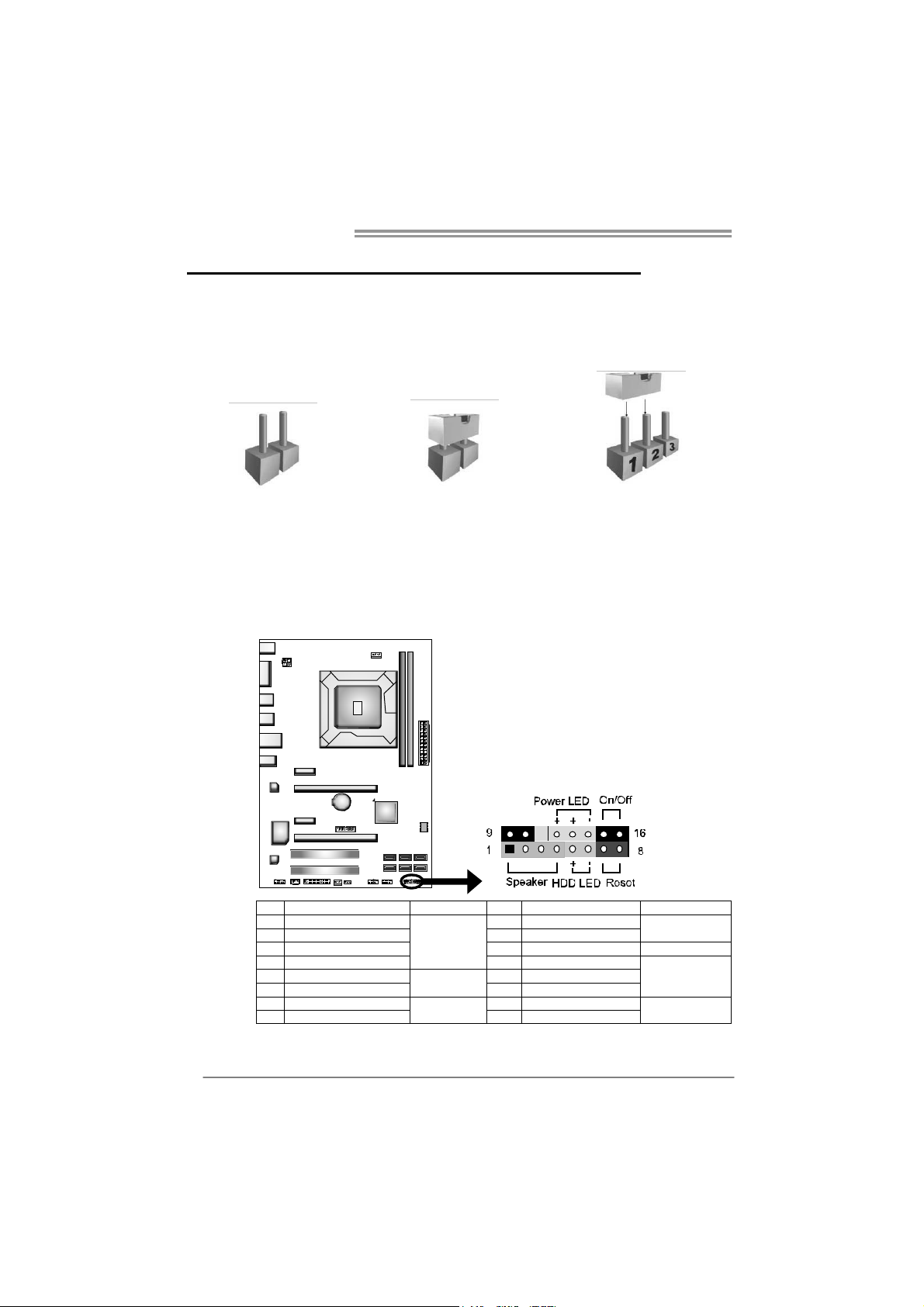
PANEL1: Front Panel Header
This 16-pin connector includes Power-on, Reset, HDD LED, Power LED, and
speaker connection. It allows user to connect the PC case’s front panel switch
functions.
14
Pin Assignment Function Pin Assignment Function
1 +5V 9 N/A
2 N/A 10 N/A
3 N/ A 1 1 N/A N/A
4 Speaker
5 HDD LED (+) 13 Power LED (+)
6 HDD LED (-)
7 Ground 15 Power button
8 Reset control
Speaker
Connector
Hard drive
LED
Reset button
12 Power LED (+)
14 Power LED (-)
16 Ground
N/A
Power LED
Power-on button
 Loading...