


TA790G X3 A2+ BIOS Manual
i
B IOS S et up.... ............ ............ ............ ............ ............ ............ .....................1
1 Main Menu...............................................................................................3
2 Adv anced Menu...... ............ ............ ............ ............ ............ ............ .........7
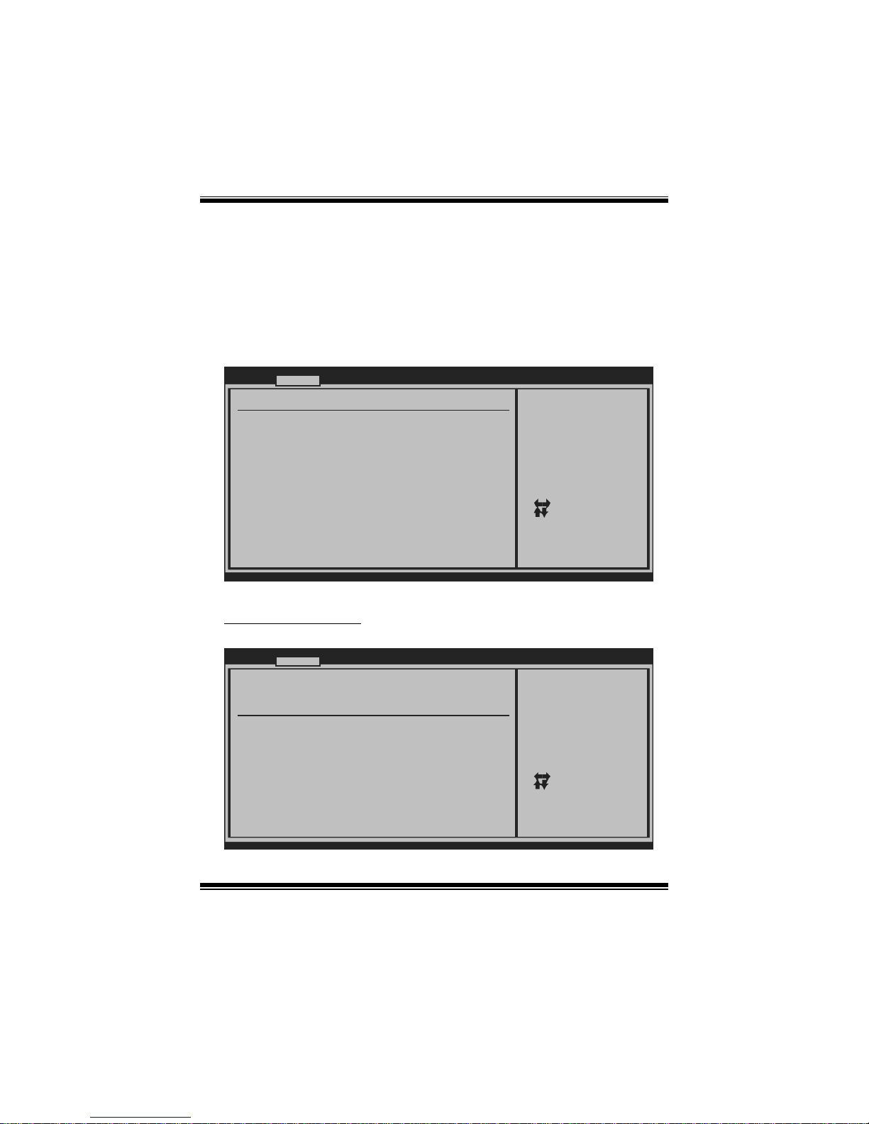
3 PCIPnP Menu........................................................................................16
4 Boot Menu..............................................................................................19
5 Chi pset Menu.........................................................................................21
6 T-Series Menu........................................................................................30
7 Exit Menu...............................................................................................42

TA790G X3 A2+ BIOS Manual
1
BIOS Setup
Introducti on
The purpose of this manual is to describe the settings in the AMI BIOS Setup
program on this motherboard. The Setup program allows users to modify the basic
system configuration and save these settings to CMOS RAM. The power of CMOS
RAM is supplied by a battery so that it retains the Setup information when the power
is turned off.
Basic Input-Output System (BIOS) determines what a computer can do without
accessing programs from a disk. T his system controls most of the input and output
devices such as keyboard, mouse, serial ports and disk drives. B IOS activates at the
first stag e o f the booting proc ess, loading and executing the operating system. S ome
additional features, such as virus and password protection or chipset fine-tuning
options are also included in BIOS.
T he rest of this manual will to guide you through the options and settings in B IOS
Setup.
Plug and Play Support
T his AMI BIOS supports the Plug and Play Version 1.0A specifi c ati on.
EPA Green PC Support
T his AMI BIOS supports Version 1. 03 of t he EPA Green PC specification.
APM Support
This AMI BIOS supports Version 1.1&1.2 of the Advanced Power Management
(AP M) speci fic ation. Power m an agement fe atures a re im pl emen ted via t he S ys tem
Management Interrupt (SMI). Sleep and Suspend power management modes are
supported. Power to the hard disk drives and video monit ors can also be m anaged by
this AMI BIOS.
ACPI Supp ort
AMI ACPI BIOS support Version 1.0/2.0 of Advanced Configuration and Power
interface specifi cation (ACP I). It provides ASL code for pow er management and
device con figuration capabilities as defined in the ACPI specific ation, developed by
Microsoft, Intel and Toshiba.

TA790G X3 A2+ BIOS Manual
2
PCI Bus Support
T his AMI BIOS also supports Version 2.3 of the Intel PCI (Peripheral Component
Int erconn ect ) local b us speci fic atio n .
DRA M Support
DDR2 SDRAM (Double Data Rate II Synchronous DR AM) is s upported.
Su ppor t e d CP Us
T his AMI BIOS supports the AMD CP U.
Using Setup
When starting up the computer, press
<Del> during the Power-On Self-Test
(POST) to enter the BIOS setup utility.
In the BIOS setup utility, you will see
General Help description at the top right
corner, and this is providing a brief
description of the selected item.
Navigation Keys for that particular menu
are at the bottom right corner, and you can
us e thes e keys to sele ct item an d ch ange
the settings.
Notice
z T he default BIOS settings apply for most conditions to ensure optimum performance
of the motherboard. If the system becomes unstable after changing any settings,
please load the default settings to ensure system’s compatibility and stability. Use
Load Setup Default under the Exit M enu.
z For better system perform ance, the BIOS firmware is being continuously updated.
T he BIOS information described in this manual is for your reference only. The actual
BIOS information and settings on board may be slightly differ ent from this manual.
z T he content of this manual is subject to be changed without notice. W e will not be
responsible for any mistakes found in this user’s manual and any system damage that
may be caused by wrong-settings.
General Help
Navigation Keys

TA790G X3 A2+ BIOS Manual
3
1 Main Menu
Once you enter AMI BIOS S etup Utility, the Main Menu will appear on the screen
providing an overview of the basic system i nformation.
BIOS SETU P U TILITY
Main Advan ced PCIPnP Boot Chipset T-Series
vxx .xx (C)Copyright 1985-200x, American Megatrends, Inc.
Se lect Screen
Se lect Item
Ch ange Field
Se lect Field
Ge neral Help
Sa ve and Exit
Exit
+Tab
F1
F10
ESC
Use [ENTER], [TAB]
or [SHIFT-TAB] to
select a field.
Use [+] or [-] to
configure system Time.
System Overvie w
AMI BIOS
System Memory
[ :0 0:00]
System Date [Tue 01/01/2008]
Floppy A
> Hard Drive C onfiguration
Version :01. 01.01
Build Date:01/ 01/08
Size :
System Time 00
Exit
AMI BI OS
Shows system information, including BIOS version and built date.
System Memory
Shows system memory size.
System Time
Set the system internal clock.
System Date
Set the system date. Note that the ‘Day’ automatically changes when you set the
date.

TA790G X3 A2+ BIOS Manual
4
Floppy A
Select the type of floppy disk drive inst all ed in your system.
Options: 360K, 5.25 in / 1.2M, 5.25 in / 720K, 3.5 i n / 1.44M, 3.5 in /
2.88M, 3.5 in / None
Hard Drive Configuration
Th e BIOS w i ll au t o m ati cal l y d etect t h e presen ce o f ID E/ SA TA devices . T h ere i s a
su b-menu fo r each IDE/S AT A dev ice. S elect a dev ice and pres s < Enter> t o en ter
the sub-menu of detailed options.
BIOS SETUP UTILITY
Main
vxx.xx (C)Copyright 1985-200x, American Megatrends, Inc.
Select Screen
Select Item
Go to Sub Screen
General Help
Save and Exit
Exit
Enter
F1
F10
ESC
While entering setup ,
BIOS auto detects th e
presence of IDE
devices. This displa ys
the status of auto
detection of IDE
devices.
IDE Confuguration
> Primary IDE Slave
> SATA 1 Device
Hard Disk Write Protect [Disabled]
IDE Detect Time Out (Sec) [35]
> SATA 2 Device
> SATA 3 Device
> SATA 4 Device
> SATA 5 Device
> SATA 6 Device
> Primary IDE Master

TA790G X3 A2+ BIOS Manual
5
Primary IDE Master/Slave ; SATA 1/2/3/4/5/6 Device
BIOS SETUP UTILITY
Main
vxx.xx (C)Copyright 1985-200x, American Megatrends, Inc.
Select Screen
Select Item
Change Option
General Help
Save and Exit
Exit
+F1
F10
ESC
Select the type
of device connected
to the system.
Primary IDE Master
LBA/Large Mode [Auto]
Block (Multi-Sector Transfer)[Auto]
PIO Mode [Auto]
DMA Mode [Auto]
S.M.A.R.T [Auto]
32Bit Data Transfer [Enabled]
Device :
Type [Auto]
The BIOS detects the information and values of respective devices, and these
information and values are shown below to the name of the sub-menu.
Type
Select the type of the IDE/SATA drive.
Options: Auto (Default) / CDROM / ARMD / Not Installed
LBA/Large Mode
Enable or disable the LBA mode.
Options: Auto (Default) / Disabled
Block (Multi-Sector Transfer)
En able o r d i s abl e mu l ti- secto r t ransfer.
Options: Auto (Default) / Disabled
PIO Mode
Select the PIO mode.
Options: Auto (Default) / 0 / 1 / 2 / 3 / 4
DMA Mode
Select the DMA mode.
Options: Auto (Default) / Disabled
S.M.A.R.T
Set the Smart Moni toring, Analysis, and Reporting T echnology.
Options: Auto (Default) / Disabled / Enabled

TA790G X3 A2+ BIOS Manual
6
32Bit Data Transfer
Enable or disable 32-bit data transfer.
Options: Enabled (Default) / Disabled
Har d Disk Write Protect
Disable or enable device write protection. T his will be effective only if the device
is accessed through BIOS.
Options: Disabled (Default) / Enabled
IDE Detect Time Out (Sec)
Select the time out value for detecting IDE/SAT A devices.
Options: 35 (Default) / 30 / 25 / 20 / 15 / 10 / 5 / 0
TA790G X3 A2+ BIOS Manual
7
2 Advanced Menu
T he Advanced M enu al lows you to configure the settings of C P U, Super I/O, Power
Management, and other system devi ces.
Notice
z Beware of that setting inappropriate values in items of this menu may cause
system to malfunction.
BIOS SETU P U TILITY
Main Advanced PCIPnP Boot Chipset T-Series
vxx .xx (C)Copyright 1985-200x, American Me gatrends, Inc.
Select Screen
Select Item
Go to Sub Screen
General Help
Save and Exit
Exit
Enter
F1
F10
ESC
Options for CPUAdvanced Setti ngs
WARNING: Setti ng wrong values in below sections
may c ause system to malfunction.
> SuperIO Conf iguration
> Smart Fan Co nfiguration
> Hardware Hea lth Configuration
> Power Config uration
> USB Configur ation
> CPU Configur ation
Exit
CPU Configurati on
T his item shows the CPU information that the BIOS automatically detects.
BIOS SETUP UTILITY
Advanc ed
vxx. xx (C)Copyright 1985-200x, American M egatrends, Inc.
Se lect Screen
Se lect Item
Ch ange Option
Ge neral Help
Sa ve and Exit
Exit
+F1
F10
ESC
Enable/Disable
Secure Virtual Machine
Mode (SVM)
CPU Configurati on
Module Version:
AGESA Version:
Physical Count:
Logical Count:
AMD CPU
Revision:
Cache L1:
Cache L2:
Cache L3:
Speed :
ncHT Speed :
Current FSB Mul tiplier:
Maximum FSB Mul tiplier:
Able to Change Freq :
uCode Patch Lev el :
Secure Virtual Machine Mode [Enab led]
Cool N Quiet [Enab led]
ACPI SRAT Table [Enab led]

TA790G X3 A2+ BIOS Manual
8
Secur e Vi rtu al Ma chin e Mo d e
Virtualization T echnology can virtually separate your system resou rce into several
parts, thus enhance the performance when running virtual machines or multi
interface system s.
Options: Enabled (Default) / Disabled
Cool N Quiet
T his item allows you to enable or disable the Cool & Quiet power saving technology.
Options: Enabled (Default) / Disabled
ACPI SRAT Ta bl e
Th e operat i n g sy s t em scans t h e ACPI SRAT at b oot t ime and u s es the i n formati o n t o
better allocate memory and schedule software threads for maximum performance.
This item controls whether the S RAT is made available to the operating system at
boot up, or not.
Options: Enabled (Default) / Disabled
S upe rI O Co nf i g urat i on
BIOS SETUP UTILITY
Advanc ed
vxx. xx (C)Copyright 1985-200x, American M egatrends, Inc.
Se lect Screen
Se lect Item
Ch ange Option
Ge neral Help
Sa ve and Exit
Exit
+F1
F10
ESC
Allows BIOS to Enable
or Disable Floppy
Controller
Configure ITE87 18 Super IO Chipset
Onboard Floppy Controller [Enab led]
Serial Port1 Ad dress [3F8/ IRQ4]
Parallel Port A ddress [378]
Parallel Port Mode [Norm al]
Parallel Port IRQ [IRQ7 ]
Keyboard PowerO n [Disa bled]
Mouse PowerOn [Disa bled]
Restore on AC P ower Loss [Powe r Off]
Onboard Floppy Controller
Select enabled if your system has a floppy disk controller (FDC) installed on the
system board and you wish to use it. If you i nstalled another FDC or t he syst em uses
no floppy drive, select disabled in this fiel d.
Options: Enabled (Default) / Disabled

TA790G X3 A2+ BIOS Manual
9
Serial Port1 Address
Select an address and corresponding i nterrupt for the first and second serial port s.
Options: 3F8/IRQ4 (Default) / 2F 8/IRQ3 / 3E8/IR Q4 / 2E8/IRQ3 / Auto / Disabled
Parallel Port Address
Th i s it em al lows yo u to det ermine acces s onboard p arallel port controller with which
I/O Address.
Options: 378 (Default) / 278 / 3BC / Disabled
Parallel Port M ode
T his item allows you to determ ine how the paral lel port should funct ion.
Options: Normal (Default) Using Parallel port as Standard P rinter Port.
EPP Using Parallel Port as Enhanced P arallel Port.
ECP Using Parallel port as Extended Capabilities Port.
ECP+EPP Using Parallel port as ECP & EPP mode.
Paralle l Port IRQ
T his item allows you to select the IRQ for the onboard parallel port.
Options: IRQ7 (Default) / IRQ5 / Disabled
Keyboard Powe rOn
T his item allows you to control the keyboard power on function.
Options: Disabled (Default) / Enabled
Mouse PowerOn
T his item allows you to control the m ouse power on function.
Options: Disabled (Default) / Enabled
Res tore on AC Power Loss
T his setting specifies how your sys tem should behave a fte r a power fail or interrupts
occurs. By choosing Disabled will leave the computer in the power off state.
Choosing Enabled will restore the system to the status before power failure or
interrupt occurs.
Options: P ower Off (Default) / P ower ON / Last State

TA790G X3 A2+ BIOS Manual
10
Smart Fan Configuration
BIOS SETUP UTILITY
Advanc ed
vxx. xx (C)Copyright 1985-200x, American M egatrends, Inc.
Se lect Screen
Se lect Item
Ch ange Option
Ge neral Help
Sa ve and Exit
Exit
+F1
F10
ESC
When you choice [Auto]
,[3Pin] or [4Pin],
please run the
calibration to define
the Fan parameters for
Smart Fan control
Smart Fan Confi guration
CPU Smart Fan [Disa bled]
Smart Fan Calib ration
Control Mode
Fan Ctrl OFF( C)
o
Fan Ctrl On(C)
Fan Ctrl Start value
Fan Ctrl Sensit ive
o
CPU Sm art Fan
This ite m allo w s you to control the CPU Smart Fan f unc tion.
Options: Disabled (default) / Auto / 4-pin / 3-pin
Sm art Fan Cal ibr ation
Choose this item and then the BIOS will auto test and detect the CP U/System fan
functions and show CPU/Sys tem fan speed.
Control Mode
T his item provides several operation modes of the fan.
Options: Quiet / Perform ance / Manual
Fan Ctrl OFF (℃ )
If the C PU/System T emperature is lower than the set value, FAN will turn off.
Options: 0~127 (℃)
Fan Ctrl On(℃ )
CPU/System fan starts to work under smart fan function when ar rive this set value.
Options: 0~127 (℃)

TA790G X3 A2+ BIOS Manual
11
Fan Ctrl S tart Val ue
When CPU/System temperature arrives to the set value, the CPU/System fan will
work under Smart Fan Function mode.
Options: 0~127 (℃)
Fan Ctrl Sensitive
Increas i n g t he val ue w ill rais e t he sp eed of C PU/Sy s t em fan.
Options: 1~127
Hardware Health C onfiguration
T his item shows the system temperature, fan speed, and voltage information.
Advanc ed
Hardware Health Configuration
H/W Health Func tion [Enab led]
Shutdown Temper ature [Disa bled]
SYS
CPU Temperature
CPU FAN Speed(J CFAN1)
CHIP FAN Speed( JNFAN1)
SYS FAN Speed(J SFAN1)
CPU VCore
NB Voltage
+3.30V
+5.00V
+12.0V
DDR Voltage
HT Voltage
5VSB
Temperature
BIOS SETUP UTILITY
vxx. xx (C)Copyright 1985-200x, American M egatrends, Inc.
Se lect Screen
Se lect Item
Ch ange Option
Ge neral Help
Sa ve and Exit
Exit
+F1
F10
ESC
Enables Hardware
Health Monitoring
Device.
H/W Health Function
If you computer contains a monitoring system, it will show PC health status during
P OST s t ag e.
Options: Enabled (Default) / Disabled
Shutdown Te m perature
T his item allows you to set up the CPU shutdown Temperature. This item is only
effective under W indows 98 ACPI mode.
Options: Disabled (Default) / 60℃/140℉ / 65℃/149℉ / 7 0 ℃/158℉ / 7 5℃/167℉
/ 80℃/ 176℉ / 85℃/185℉ / 90 ℃/194℉

TA790G X3 A2+ BIOS Manual
12
Power Configuration
BIOS SETUP UTILITY
Advanc ed
vxx. xx (C)Copyright 1985-200x, American M egatrends, Inc.
Se lect Screen
Se lect Item
Ch ange Option
Ge neral Help
Sa ve and Exit
Exit
+F1
F10
ESC
Select the ACPI
state used for
System Suspend.
ACPI Settings
Suspend mode [S1 ( POS)]
ACPI Version Fe atures [ACPI v1.0]
ACPI APIC suppo rt [Enab led]
AMI OEMB table [Enab led]
Headless mode [Disa bled]
RTC Resume [Disa bled]
RTC Alarm Date( Days)
Time
USB Wakeup From S3/S4 [Disa bled]
Power On by LAN [Disa bled]
RTC Alarm
Sus pend mode
T he item allows you to sel ect the sus pend type under the AC PI operating system.
Opt i ons : S1 (P OS) (Defaul t ) Po wer on S usp end
S3 (STR) Suspend to RAM
S1 & S3 POS+STR
ACPI Version Features
Th e item al l o ws yo u to sel ect t he vers i o n of ACPI.
Options: ACPI v1.0 (Default) / ACP I v2.0
ACPI APIC support
This item is used to enable or disable the motherboard's APIC (Advan ced
Programmable Interrupt Controller). The APIC provides multiprocessor support,
more IRQs and faste r interrupt handling.
Options: Enabled (Default) / Disabled
AMI OEMB table
Set this value to allow the ACPI B IOS to add a pointer to an OEMB table in the Root
System Descri ption Table (RS DT ) table.
Options: Enabled (Default) / Disabled

TA790G X3 A2+ BIOS Manual
13
Headless mode
This is a server-specific feature. A headless server is one that operates without a
keyboard, monitor or mouse. To run in headless mode, both BIOS and operating
system (e.g. Wi ndows Server 2003) must support headless operation.
Options: Disabled (Default) / Enabled
RTC Resume
When “ Enabled”, you can set the date and time at which the RTC (real-time clock)
alarm aw akens th e s ys tem from S u s p end mod e.
Options: Disabled (Default) / Enabled
RTC Alar m Date (Days)
You can choose which date the sys tem will boot up.
RTC Ala r m Ti m e
You can choose the system boot up time, input hour, minut e and second to specify.
USB Wakeup from S3/S4
T his item allows you to enable or disabled the USB resume from S 3/S 4 function.
Options: Disabled (Default) / Enabled
Power On by LAN
T his item allows you control the wake on LAN (WOL) function.
Options: Disabled (Default) / Enabled
 Loading...