

Page 1

TA760G M 2+ BIO S Man ual
i
B IOS Setup.... ............ ............ ............ ............ ............ ............ ............ .........1
1 Main Menu...............................................................................................3
2 Adv an ced Menu...... ............ ............ ............ ............ ............ ............ .........6
3 PCIPnP Menu........................................................................................16
4 Boot Menu..............................................................................................19
5 Chipset Menu.........................................................................................21
6 T-Series Menu........................................................................................28
7 Exit Menu...............................................................................................39
Page 2

TA760G M 2+ BIO S Man ual
BIOS Setup
Introducti on
The purpose of this manual is to describe the settings in the AMI BIOS Setup
program on this motherboard. The Setup program allows users to modify the basic
system configuration and save these settings to CMOS RAM. The power of CMOS
RAM is supplied by a battery so that it retains the Setup information when the power
is turned off.
Basic Input-Output System (BIOS) determines what a computer can do without
accessing programs from a disk. T his system controls most of the input and output
devices such as keyboard, m ouse, serial ports and disk drives. BIOS activates at the
first stag e o f the booting process, l oading and executing the operating system. Some
additional features, such as virus and password protection or chipset fine-tuning
options are also included in BIOS.
T he rest of this manual will to guide you through the options and settings in BIOS
Setup.
Plug and P l ay Support
T his AMI BIOS supports the Plug and Play Vers ion 1.0A specifi c ati on.
EPA Green PC Support
T his AMI BIOS supports Version 1. 03 of the EPA Green PC specification.
APM Support
This AMI BIOS supports Version 1.1&1.2 of the Advanced Power Management
(AP M) speci fic ation. Power m anagement features a re im pl emented via the System
Management Interrupt (SMI). Sleep and Suspend power management modes are
supported. P ower to the hard disk drives and video monit ors can also be m anaged by
this AMI BIOS.
ACPI Support
AMI ACPI BIOS support Version 1.0/2.0 of Advanced Configuration and Power
interfa ce specifi cation (ACPI). It provides ASL code for pow er management and
device con figuration capabilities as defined in the ACPI specification, developed by
Microso ft, Intel and T oshiba.
1
Page 3
TA760G M 2+ BIO S Man ual
PCI Bus Support
T his AMI BIOS also supports Version 2.3 of the Intel PCI (Peripheral Component
Int erconn ect ) local b us speci fic atio n .
DRAM Support
DDR2 SDRAM (Double Data Rate II Synchronous DRAM) is supported.
Su ppor t e d CP Us
T his AMI BIOS supports the AMD C P U.
Usin g Setup
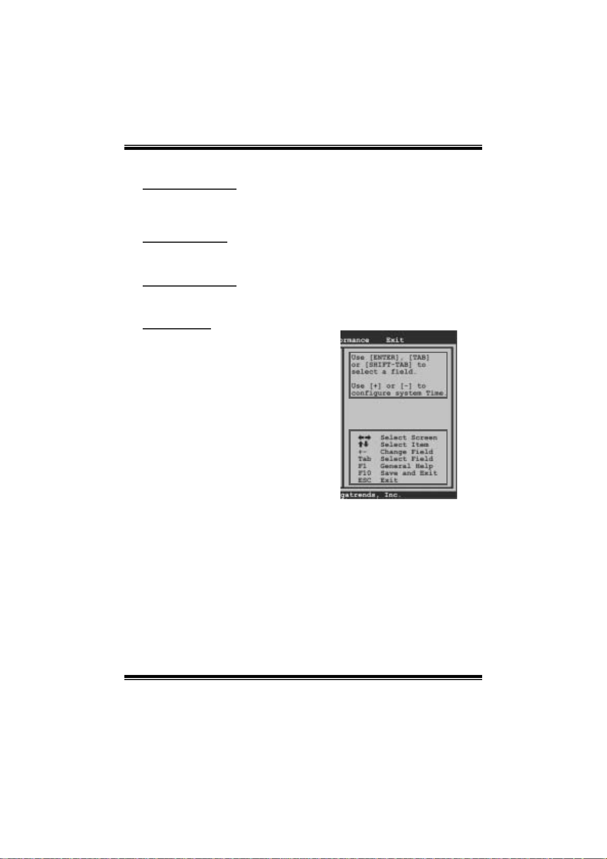
When starting up the computer, press
<Del> during the Power-On Self-Test
(POST) to enter the BIOS setup utility.
In the BIOS setup utility, you will see
General Help description at the top right
corner, and this is providing a brief
description of the selected item.
Navigation Keys for that particular menu
are at the bottom right corner, and you can
us e thes e keys to select item and ch ange
the settings.
Notice
z T he default BIOS settings apply for most conditions to ensure optimum performance
of the motherboard. If the system becomes unstable after changing any settings,
please load the default settings to ensure system’s compatibility and stability. Use
Load Setup Default under the Exit Menu.
z For better system perform ance, the BIOS firmwa re is being continuously updated.
T he BIOS information described in this manual is for your reference onl y. The actual
BIOS information and settings on board may be slightly different from this manual.
z T he content of this manual is subject to be changed without notice. W e will not be
responsible for any mist akes found in this user’ s manual and any system damage that
may be caused by wrong-settings.
General Help
Navigation Keys
2
Page 4
TA760G M 2+ BIO S Man ual
1 Main Menu
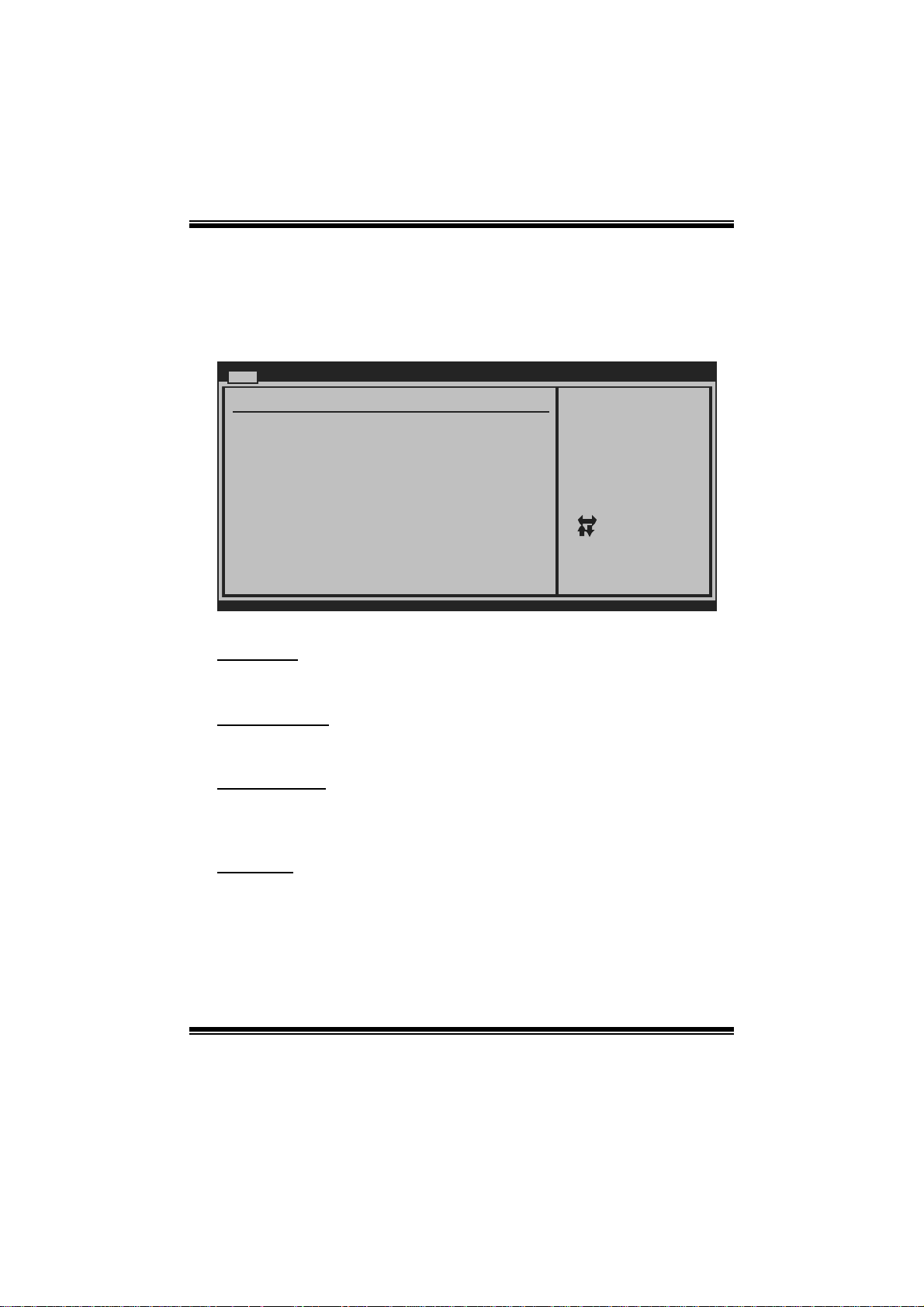
Once you enter AMI BIOS Setup Utility, the Main Menu will appear on the screen
providing an overview of t he basic system information.
Main Advan ced PCIPnP Boot Chipset T-Series
System Overvie w
AMI BIOS
Version :01. 01.01
Build Date:01/ 01/08
System Time 00
System Date [Tue 01/01/2008]
Floppy A
> IDE Configur ation
vxx .xx (C)Copyright 1985-200x, American Megatrends, Inc.
AM I BI O S
BIOS SETU P UTILITY
[ :00:00]
Exit
Use [ENTER], [TAB]
or [SHIFT-TAB] to
select a field.
Use [+] or [-] to
configure system Time.
Select Screen
Select Item
Change Field
+-
Select Field
Tab
General Help
F1
Save and Exit
F10
Exit
ESC
Shows system information including BIOS version and built dat e.
System Ti me
Set the system internal clock.
System Date
Set the system date. Note that the ‘Day’ automatically changes when you set the
date.
Floppy A
Select the type of fl oppy disk dri ve inst all ed in your system.
Options: 360K, 5. 25 in / 1.2M, 5.25 in / 720K, 3.5 i n / 1.44M, 3.5 in /
2.88M, 3.5 in / None
3
Page 5
TA760G M 2+ BIO S Man ual
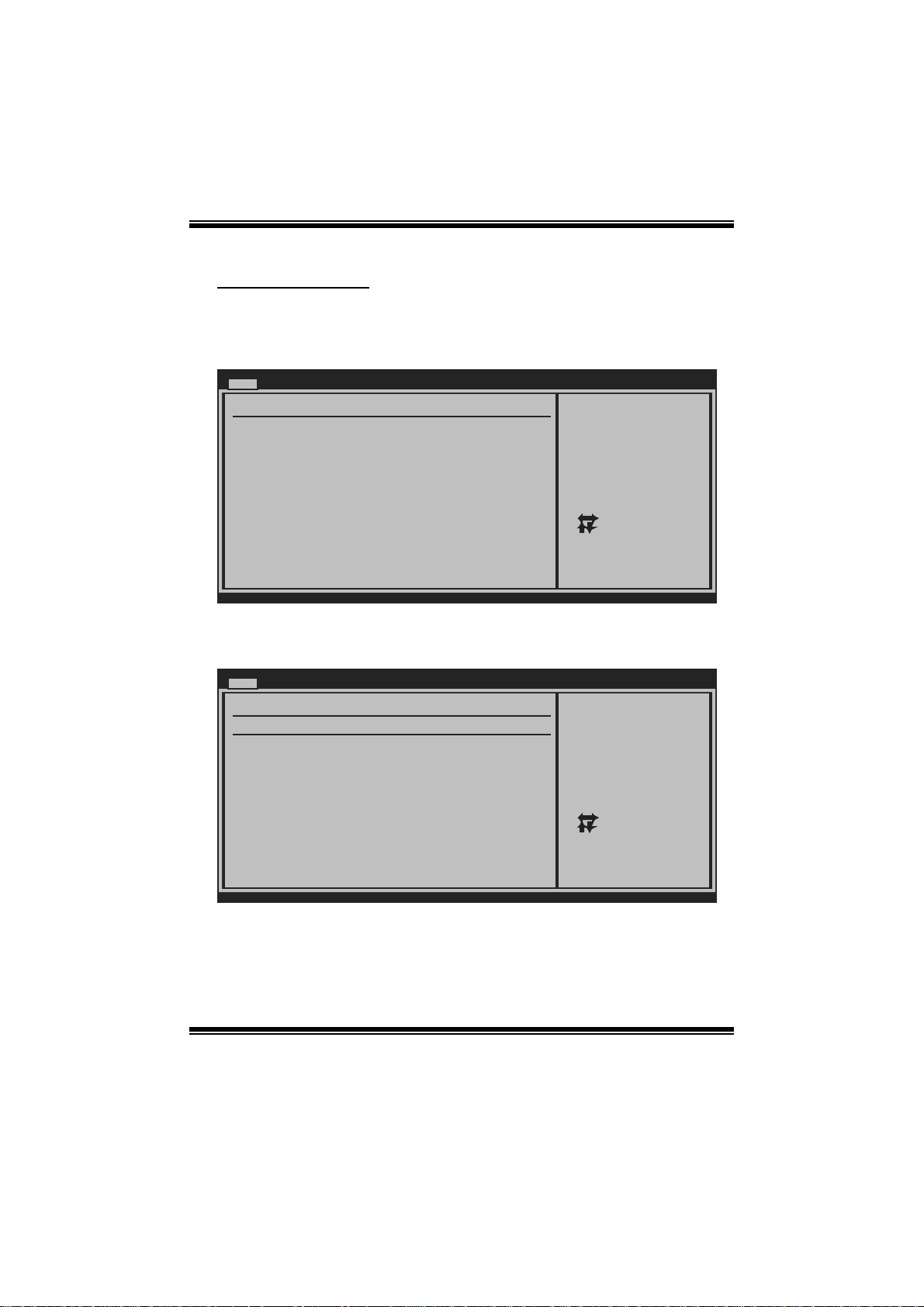
IDE Configuration
The BIO S w i ll au t o m ati cal l y detect t h e presen c e o f ID E / SAT A d evices . T h ere i s a
su b-menu fo r each IDE/SATA d evice. S elect a device and press <E nter> t o en ter
the sub-menu of detailed opt ions.
Main
IDE Confuguration
> Primary IDE Master
> Primary IDE Slave
> SATA 1 Device
> SATA 2 Device
> SATA 3 Device
> SATA 4 Device
> SATA 5 Device
> SATA 6 Device
Hard Disk Write Protect [Disabled]
IDE Detect Time Out (Sec) [35]
BIOS SETUP UTILITY
While entering setup ,
BIOS auto detects th e
presence of IDE
devices. This displa ys
the status of auto
detection of IDE
devices.
Select Screen
Select Item
Go to Sub Screen
Enter
General Help
F1
Save and Exit
F10
Exit
ESC
vxx.xx (C)Copyright 1985-200x, American Megatrends, Inc.
Primary IDE Master/Slave ; SATA 1/2/3/4/5/6 Device
Main
Primary IDE Master
Device :
Type [Auto]
LBA/Large Mode [Auto]
Block (Multi-Sector Transfer)[Auto]
PIO Mode [Auto]
DMA Mode [Auto]
S.M.A.R.T [Auto]
32Bit Data Transfer [Enabled]
vxx.xx (C)Copyright 1985-200x, American Megatrends, Inc.
BIOS SETUP UTILITY
Select the type
of device connected
to the system.
Select Screen
Select Item
Change Option
+-
General Help
F1
Save and Exit
F10
Exit
ESC
The BIOS detects the information and values of respective devices, and these
information and values are shown below to the name of the sub-menu.
4
Page 6

TA760G M 2+ BIO S Man ual
Type
Select the type of the IDE/SAT A drive.
Options: Auto (Default) / CDROM / AR MD / Not Installed
LBA/Large Mode
Enable or disabl e the LBA mode.
Options: Auto (Default) / Disabled
Block (Multi-Sector Transfer)
En able o r d i s abl e mul ti -s ect o r t ransfer.
Options: Auto (Default) / Disabled
PIO Mode
Select the PIO mode.
Options: Auto (Default) / 0 / 1 / 2 / 3 / 4
DMA Mode
Select the DMA mode.
Opti ons: Auto (Default ) / S WDMA0 ~ 2 / MW DMA0 ~ 2 / UDMA0 ~ 5
S.M.A.R.T
Set the Smart Moni toring, Analys is, and Reporting T echnology.
Options: Auto (Default) / Disabled / Enabled
32Bit Data Transfer
Enable or disabl e 32-bit data transfer.
Options: Enabled (Default) / Disabled
Har d Disk Write Protect
Disable or enable device write protection. T his will be effective only if the device
is accessed through BIOS .
Options: Disabled (Default) / Enabled
IDE Detect Time Out (Sec)
Select the time out value for detecting IDE/SATA devices.
Options: 35 (De fault) / 30 / 25 / 20 / 15 / 10 / 5 / 0
5
Page 7
TA760G M 2+ BIO S Man ual
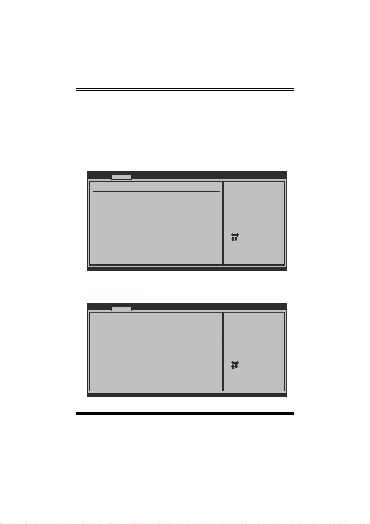
2 Advanced Menu
T he Advanced M enu all ows you to configu re the settings o f CP U, Super I/O, P ower
Management, and other system devices .
Notice
z Beware of that setting inappropriate values in items of this menu may cause
system to malfunction.
Main Advanced PCIPnP Boot Chipset T-Series
WARNING: Setting wrong values in below sec tions
may cause system to m alfunction.
> CPU Configuration
> SuperIO Configuration
> Smart Fan Configuration
> Hardware Health Configuratio n
> Power Configuration
> USB Configuration
BIOS SETUP UTILITY
Configure CPU.Advanced Settings
Exit
Select Screen
Select Item
Go to Sub Screen
Enter
General Help
F1
Save and Exit
F10
Exit
ESC
vxx.xx (C)Copyright 1985-200x, Amer ican Megatre nds, Inc.
CPU Confi guration
T his item shows the CPU information that the BIOS automatically detects.
Advanced
CPU Configuration
Module Version:
AGESA Version:
Physical Count:
Logical Count:
AMD CPU
Revision:
Cache L1:
Cache L2:
Cache L3:
Speed :
Able to Change Freq :
uCode Patch Level :
Secure Virtual Machine Mode [ Enabled]
PowerNow [ Enabled]
ACPI SRAT Table [ Enabled]
CPU Prefetching [ Enabled]
vxx.xx (C)Copyright 1985-200x, Amer ican Megatre nds, Inc.
BIOS SETUP UTILITY
6
Enable/Disable
Secure Virtual Machine
Mode (SVM)
Select Screen
Select Item
+-
Change Option
F1
General Help
F10
Save and Exit
ESC
Exit
Page 8
TA760G M 2+ BIO S Man ual
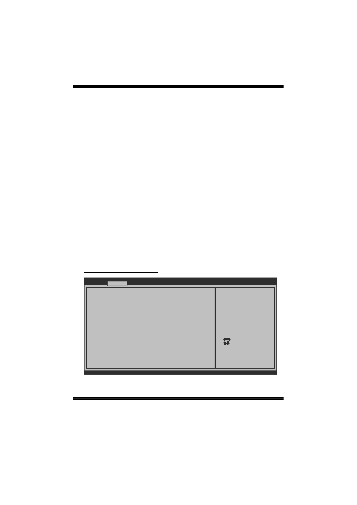
Secur e Vi r t ual Ma chine Mode
Virtualization T echnology can virtually separate your system resou rce into several
parts, thus enhance the performance when running virtual machines or multi
interface systems.
Options: Enabled (Default) / Disabled
PowerNow
T his item allows you t o enable or disable the P owerNow power saving technology.
Options: Enabled (Default) / Disabled
ACPI SRAT Ta bl e
The operat i n g sy s t em scans t h e ACPI SRAT at b oot t im e and u s es the i n format i o n t o
better allocate memory and schedule software threads for maximum performance.
This item controls whether the SRAT is made available to the operating system at
boot up, or not.
Options: Enabled (Default) / Disabled
CPU Prefetching
T his item allows you t o enable or disable CPU Prefetching fun ction.
Options: Enabled (Default) / Disabled
S uperI O Co n f i g urati o n
Advanced
Configure ITE8718 Super IO Chi pset
Onboard Floppy Controller [ Enabled]
Serial Port1 Address [ 3F8/IRQ4]
Parallel Port Address [ 378]
Parallel Port Mode [ Normal]
Parallel Port IRQ [ IRQ7]
Keyboard PowerOn [ Disabled]
Mouse PowerOn [ Disabled]
Restore on AC Power Loss [ Power Off]
vxx.xx (C)Copyright 1985-200x, Amer ican Megatre nds, Inc.
BIOS SETUP UTILITY
7
Allows BIOS to Enable
or Disable Floppy
Controller
Select Screen
Select Item
Change Option
+-
General Help
F1
Save and Exit
F10
Exit
ESC
Page 9

TA760G M 2+ BIO S Man ual
Onboard Floppy Controller
Select enabled if your system has a floppy disk controller (FDC) installed on the
system board and you wish to use it. If you installed another FDC or the system uses
no floppy drive, select disabled in this field.
Options: Enabled (Default) / Disabled
Serial Port1 Address
Select an address and corr espondi ng interrupt for the first and second seri al ports.
Options: 3F8/IRQ4 (Default) / 2F 8/IRQ3 / 3E8/IRQ4 / 2E8/IRQ3 / Disabled
Parallel Port Address
Thi s i t em al l ows yo u to det ermine acces s onboard parallel port controller with which
I/O Address.
Options: 378 (De fault) / 278 / 3BC / Disabled
Parallel Port Mode
T his item allows you t o determine how the parallel port should function.
Options: Normal (Default) Using Parallel port as Standard Printer Port.
EPP Using Parallel Port as Enhanced Parallel Port.
ECP Using Parallel port as Extended Capabilities Port.
ECP +EPP Using Parallel port as ECP & EPP mode.
ECP Mode DMA Channel
T his item allows you t o select parallel port ECP DMA.
Opti ons: DMA3 (Defaul t) / DMA0 / DMA1
Paralle l Port IRQ
T his item allows you t o select the IRQ for the onboard parallel port.
Options: IRQ7 (Default) / IR Q5 / Disabled
Keyboard PowerOn
T his item allows you t o control the keyboard power on function.
Options: Disabl ed (De fault) / S pecific Key / Stroke Key
8
Page 10

TA760G M 2+ BIO S Man ual
Specific Key Enter
T his item will show only when Keyboard P owerOn is set “Specific Key.”
Stroke Keys Selected
T his item will show only when Keyboard P owerOn is set “Stroke Key.”
Options: C trl+F 1 (Default) / Wake Key / Power Key / Ctrl+F 2 / Ctrl+F3 /
Ctrl +F4 / Ctrl+F5 / Ctrl+F6
Mouse PowerOn
T his item allows you t o control the m ouse power on function.
Options: Disabled (Default) / Enabled
Restore on AC P owe r Loss
T his setting specifi es how your sys tem should behave a fte r a power fail or interrupts
occurs. By choosing Disabled will leave the computer in the power off state.
Choosing Enabled will restore the system to the status before power failure or
interrupt occurs.
Options: P ower Off (De fault) / P ower ON / Last State
Smart F an Configuration
Advan ced
Smart Fan Conf iguration
CPU Smart Fan [Disabled]
Smart Fan Cali bration
Control Mode
Fan Ctrl OFF( C)
Fan Ctrl On(C)
Fan Ctrl Start value
Fan Ctrl Sensi tive
o
o
BIOS SETU P UTILITY
When you choice [Auto]
,[3Pin] or [4Pin],
please run the
calibration to define
the Fan parameters for
Smart Fan control
vxx .xx (C)Copyright 1985-200x, American Megatrends, Inc.
CPU Sm art Fan
This ite m a llo w s you to c ontr ol the CPU Sma r t Fan functio n.
Options: Disabl ed (default) / Auto / 4-pin / 3-pin
9
Select Screen
Select Item
Change Option
+-
General Help
F1
Save and Exit
F10
Exit
ESC
Page 11

TA760G M 2+ BIO S Man ual
Sm art Fan Cal ibr ation
Choose this item and then the BIOS will auto test and detect the CPU/System fan
functions and show CPU/S ystem fan speed.
Control Mode
T his item provides several operation modes of the fan.
Options: Quiet / Performan ce / Manual
Fan Ctrl OFF(℃ )
If the C PU/System T emperature is lower than the set value, FAN will turn off.
Options: 0~127 (℃) (With the interval of 1℃)
Fan Ctrl On(℃ )
CPU/System fan starts to work under smart fan function when arrive this set value.
Options: 0~127 (℃) (With the interval of 1℃)
Fan Ctrl S tart Val ue
When CPU/System temperature arrives to the set value, the CPU/S ystem fan will
work under Smart Fan Function mode.
Options: 0~127 (W ith the interval of 1)
Fan Ctrl Sensiti ve
Increasin g t h e val u e w ill rai s e t he sp eed of CP U / Sys t em fan.
Options: 1~127 (W ith the interval of 1)
10
Page 12
TA760G M 2+ BIO S Man ual
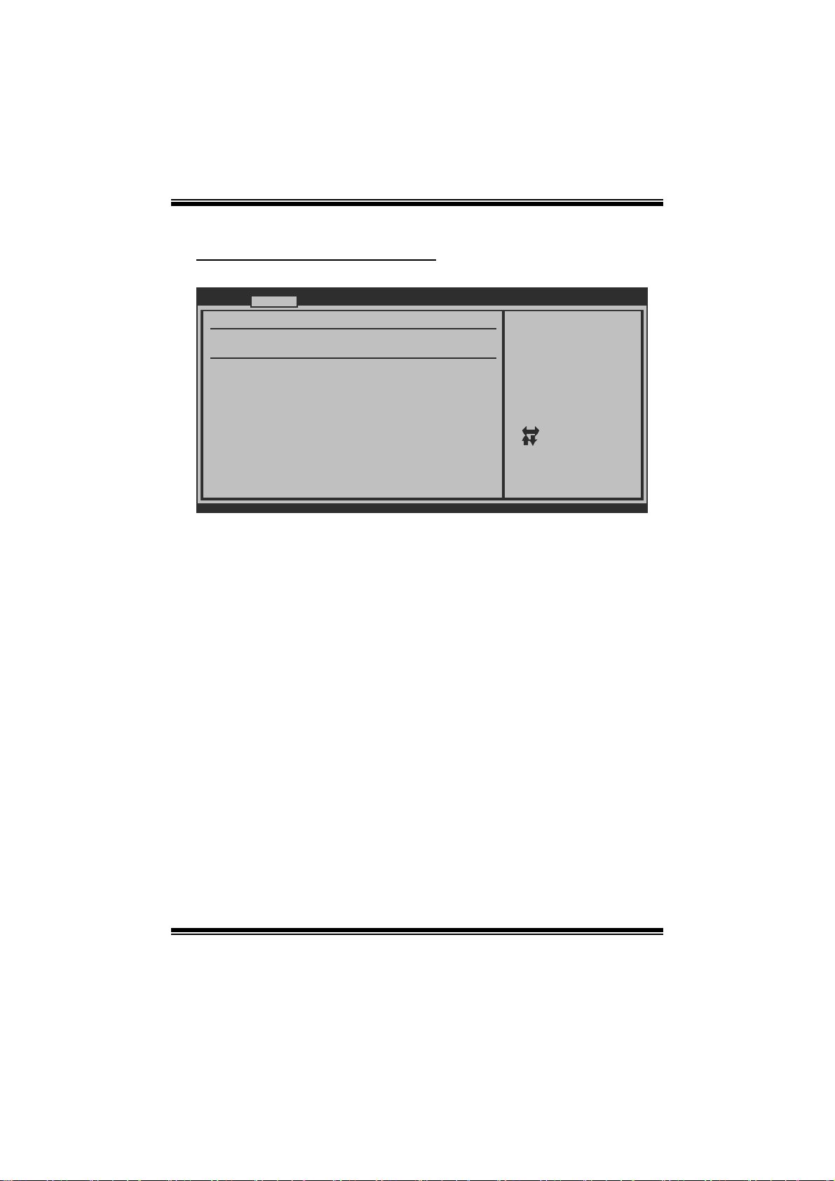
Hardware Health Configuration
T his item shows the system temperature, fan speed, and volt age information.
Advanced
Hardware Health Configuration
H/W Health Function [Enabled]
Shutdown Temperature [Disabled]
SYS Temperature
CPU Temperature
CPU FAN Speed(JCFAN1)
SYS FAN Speed(JSFAN1)
CPU Voltage
Chip Voltage
+3.30V
+5.00V
+12.0V
DDR Voltage
HT Voltage
5VSB
vxx.xx (C)Copyright 1985-200x, American Megatre nds, Inc.
H/W Health Functio n
If you computer contains a monitoring system, it will show PC health status during
P OST s t ag e.
Options: Enabled (Default) / Disabled
Shutdown Tempe rature
BIOS SETUP UTILITY
Enables Hardware
Health Monitoring
Device.
Select Screen
Select Item
Change Option
+-
General Help
F1
Save and Exit
F10
Exit
ESC
T his item allows you to set up the CPU shutdown T emperature. This item is only
effective under Wi ndows 98 ACP I m ode.
Options: Disabled (Default) / 60℃/140℉ / 65 ℃/149℉ / 7 0 ℃/158℉ / 7 5℃/167℉
/ 80℃/ 176℉ / 85℃/185℉ / 90℃/194℉
11
Page 13
TA760G M 2+ BIO S Man ual
Power Configuration
Advanced
Power Configuration
Suspend mode [S1 (POS)]
ACPI Version Features [ACPI v1.0]
ACPI APIC support [Enabled]
AMI OEMB table [Enabled]
Headless mode [Disabled]
RTC Resume [Disabled]
RTC Alarm Date (Days)
RTC Alarm Time (HH:MM:SS)
USB Resume from S3/S4 [Disabled]
Power On by PCIE/Onboard LAN
Wake Up by PCI [Disabled]
Wake on Ring [Disabled]
BIOS SETUP UTILITY
[Disabled]
Select the ACPI
state used for
System Suspend.
Select Screen
Select Item
Go to Sub Screen
Enter
General Help
F1
Save and Exit
F10
Exit
ESC
vxx.xx (C)Copyright 1985-200x, American Megatre nds, Inc.
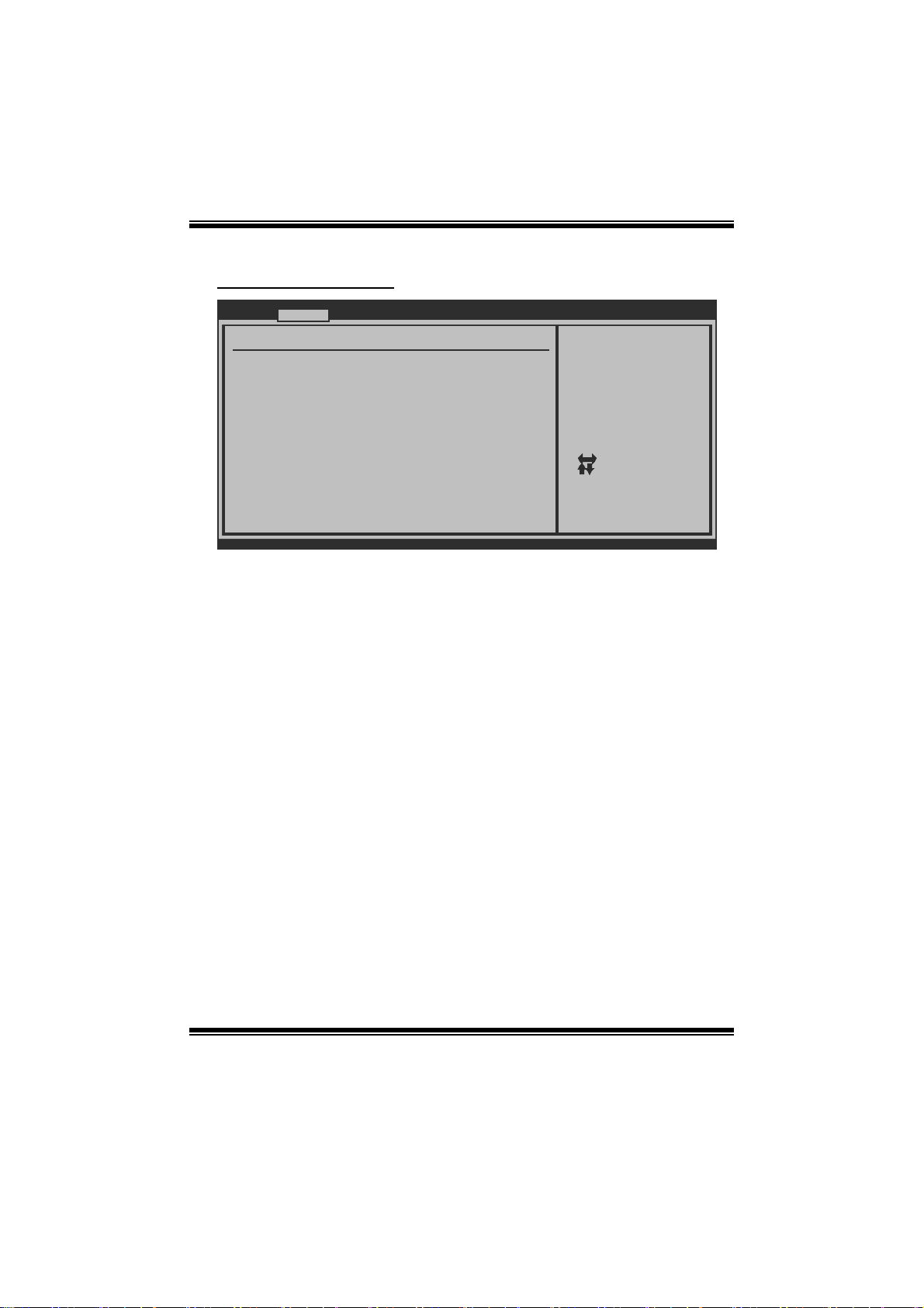
Suspe nd m ode
T he item allows you to select the s uspend type under the ACP I operating system.
Opt i ons : S1 (POS) (Defaul t ) Po wer on S uspen d
S3 (STR) Suspend to RAM
S1 & S3 POS+STR
ACPI Version Features
The it em all o ws y o u to sel ect t he vers i o n of AC PI.
Options: ACPI v1.0 (Default) / AC PI v2.0 / ACP I v3. 0
ACPI AP I C support
This item is used to enable or disable the motherboard's APIC (Advan ced
Programmable Interrupt Controller). The APIC provides multiprocessor support,
more IRQs and faste r interrupt handling.
Options: Enabled (Default) / Disabled
AMI OEMB table
Set this value to allow the ACPI B IOS to add a pointer to an OEMB table in the Root
Syst em Descri ption Table (RS DT ) table.
Options: Enabled (Default) / Disabled
12
Page 14

TA760G M 2+ BIO S Man ual
Headless mode
This is a server-specific feature. A headless server is one that operates without a
keyboard, monitor or mouse. To run in headless mode, both BIOS and operating
system (e.g. Windows Server 2003) must support headless operat ion.
Options: Disabled (Default) / Enabled
RTC Resume
When “ Enabled”, you can set the date and time at which the RT C (real-time clock)
alar m awaken s th e s y s tem from S u s p en d mo d e.
Options: Disabled (Default) / Enabled
RTC Alarm Da te (Days )
You can choose which date the syst em will boot up.
RTC Ala r m Ti m e (HH:MM:SS)
You can choose the system boot up time, input hour, minut e and second to specify.
USB Resume from S3/S4
T his item allows you t o enable or disabled the USB resume from S 3/S4 functi on.
Options: Disabled (Default) / Enabled
Power O n by PCIE / Onboard LAN
T his item allows you control the wake on LAN (WOL) funct ion.
Options: Disabled (Default) / Enabled
Wake Up by PCI
T his item allows you control the wakeup by PC I function.
Options: Disabled (Default) / Enabled
Wake O n Ring
T his item allows you control the wake on ring function.
Options: Disabled (Default) / Enabled
13
Page 15
TA760G M 2+ BIO S Man ual
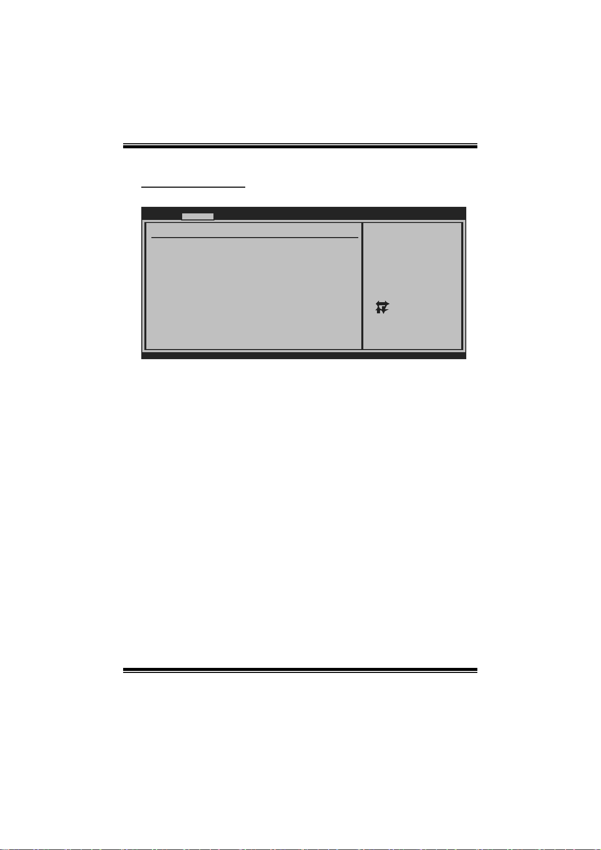
USB Confi guration
T his item shows the USB controller and using USB device information.
Advanced
USB Configuration
Module Version - 2.24.2-13.4
USB Devices Enabled:
Legacy USB Support [Enabled]
USB 2.0 Controller Mode [HiSpeed]
BIOS EHCI Hand-Off [Enabled]
> USB Mass Storage Device Configuration
BIOS SETUP UTILITY
Enables support for
legacy USB. AUTO
option disables
legacy support if
no USB devices are
connected.
Select Screen
Select Item
+-
Change Option
F1
General Help
F10
Save and Exit
ESC
Exit
vxx.xx (C)Copyright 1985-200x, American Megatrends, Inc.
Legacy USB Suppor t
T his item determines if the BIOS should provide legacy support fo r USB devices
li ke the key board, mouse, and US B drive. This is a useful feat ure when u sing s uch
USB devices with operating systems that do not natively support USB (e.g.
Microsoft DOS or Windows NT).
Options: Enabled (Default) / Disabled
USB 2.0 Controller Mode
T his item allows you t o select the operation mode of the USB 2. 0 controller.
Options: HiSpeed (Default) US B 2.0-480Mbps
FullSpeed USB 1.1-12Mbps
BIO S EHCI Hand-Off
This item allows you to enable support for operating systems without an EHCI
hand-o ff feature.
Options: Enabled (Default) / Disabled
14
Page 16
TA760G M 2+ BIO S Man ual
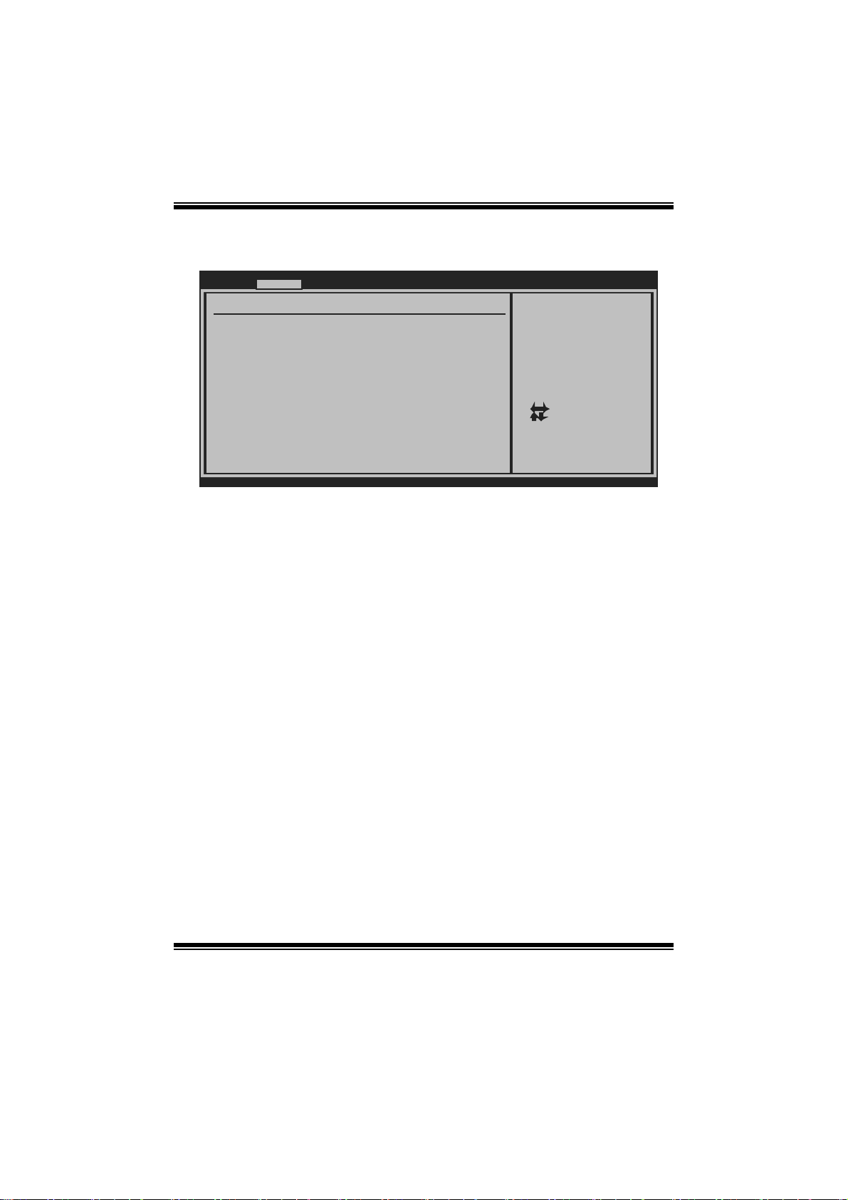
US B Ma ss S torag e De vice Co n f ig urat io n
Advanced
USB Mass Storage Device Configuration
USB Mass Storage Reset Delay [20 Sec]
Device #
Emulation Type [Auto]
vxx.xx (C)Copyright 1985-200x, American Megatrends, Inc.
BIOS SETUP UTILITY
Number of seconds
POST waits for the
USB mass storage
device after start
unit command.
Select Screen
Select Item
Change Option
+-
General Help
F1
Save and Exit
F10
Exit
ESC
USB Mass Storage Reset Delay
T his item allows you t o set t he reset delay for USB mass storage device.
Op t i ons : 2 0 S ec (D efau l t ) / 10 S ec / 3 0 S ec / 4 0 S ec
E m ulati o n T ype
T his item allows you t o select the emulation type of the USB mass storage device.
Options: Auto (Default) / Floppy / Forced FDD / Hard Disk / CDROM
15
Page 17
TA760G M 2+ BIO S Man ual
3 PCIPnP Menu
T his section describes con figuring the PCI bus system. PC I, or Personal Computer
Interconnect, is a system which allows I/O devices to operate at speeds nearing the
speed o f the CP U itself uses when communicating with its own special components.
Notice
z Beware of that setting inappropriate values in items of this menu may cause
system to malfunction.
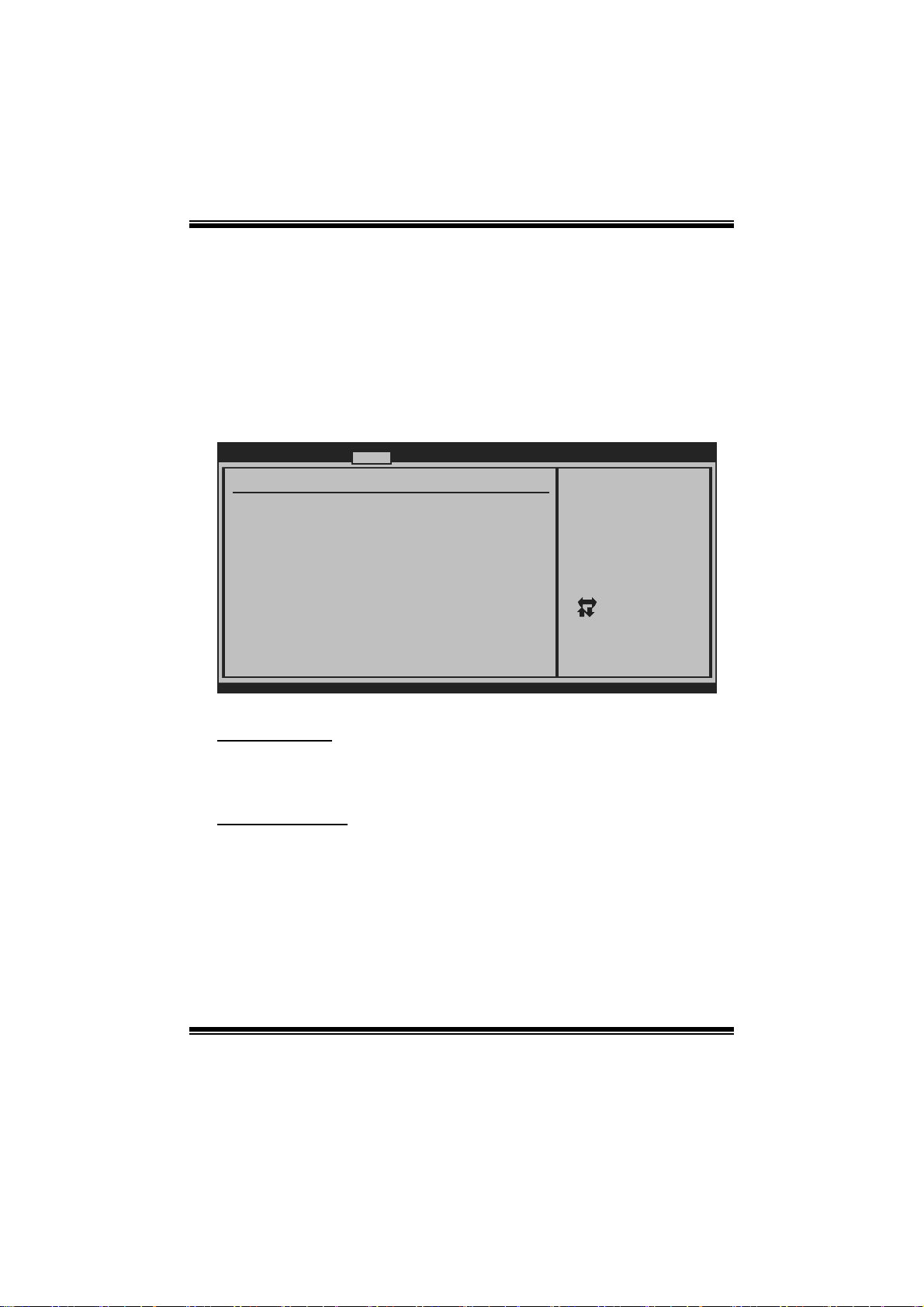
Main Advanced PCIPnP Boot Chipset T-Series
Advanced PCI/P nP Settings
WARNING: Setti ng wrong values in below sections
may c ause system to malfunction.
Clear NVRAM [No]
Plug & Play O/ S [No]
PCI Latency Ti mer [64]
Allocate IRQ t o PCI VGA [Yes]
Palette Snoopi ng [Disabled]
PCI IDE BusMas ter [Enabled]
> PCI Resource
> PCI Express Configuration
BIOS SETU P UTILITY
Clear NVRAM during
System Boot.
Select Screen
Select Item
Change Option
+-
General Help
F1
Save and Exit
F10
ESC
Exit
Exit
vxx .xx (C)Copyright 1985-200x, American Megatrends, Inc.
Clear NVRAM
T his item allows you t o clear the data in t he NVRAM (CMOS) by selecting “ Yes”.
Options: No (Default) / Yes
Plug & Play OS
When set to YES, BIOS will only initialize the PnP cards used for the boot sequen ce
(VGA, IDE, SCSI). The rest of the cards will be initialized by the PnP operating
system like Window™ 95. When set to NO, BIOS will initialize all the PnP cards.
For non-PnP operating systems (DOS, Netware™), this option must set to NO.
Options: No (Default) / Yes
16
Page 18
TA760G M 2+ BIO S Man ual
PCI Latency Tim er
T his item cont rols how l ong a PCI device can hold the PCI bus befor e anothe r takes
over. T he longer the latency, the longer the P CI device can retain control of the bus
before handing i t over to another PCI device.
Options: 64 (De fault) / 0-255
Al locate IRQ to P CI VGA
T his item allows BIOS to choose a IRQ to assign for the PCI VGA card.
Opti ons: Yes (Default) / No
Pale tte Snooping
Som e old graphic controllers need to “ snoop” on the VGA palette and then map it to
their display as a way to provi de boot i nformation and VGA compati bility. This item
allows such snooping to take place.
Options: Disabled (Default) / Enabled
PCI IDE BusMaster
T his item is a toggle for the built-in driver that allows the onbo ard ID E controller to
perform DM A (Di rect Mem o ry Acces s ) trans fers .
Options: Enabled (Default) / Disabled
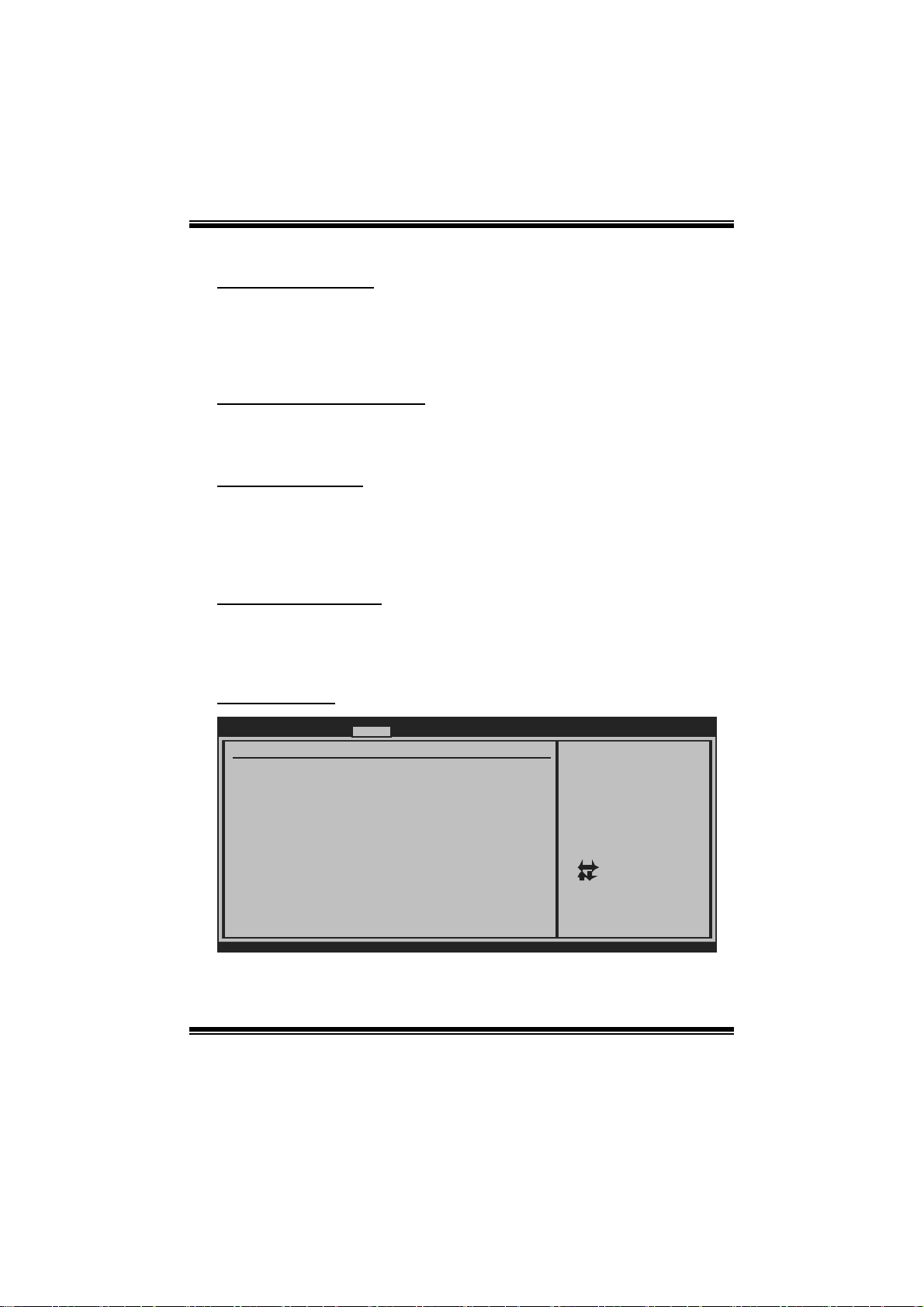
PCI Resource
PCIPnP
PCI Resource
IRQ3 [Available]
IRQ4 [Available]
IRQ5 [Available]
IRQ7 [Available]
IRQ9 [Available]
IRQ10 [Available]
IRQ11 [Available]
IRQ14 [Available]
IRQ15 [Available]
DMA Channel 0 [Available]
DMA Channel 1 [Available]
DMA Channel 3 [Available]
DMA Channel 5 [Available]
DMA Channel 6 [Available]
DMA Channel 7 [Available]
Reserved Memory Size [Disabled]
vxx.xx (C)Copyright 1985-200x, American Megatrends, Inc.
BIOS SETUP UTILITY
17
Available: Specified
IRQ is available to be
used by PCI/PnP
devices.
Reserved: Specified
IRQ is reserved for
use by Legacy ISA
devices.
Select Screen
Select Item
+-
Change Option
F1
General Help
F10
Save and Exit
ESC
Exit
Page 19
TA760G M 2+ BIO S Man ual
IRQ3/4/5/7/9/1 0/11/14/15
T hese items will allow you to assign each system interrupt a type, depending on the
type of device using the interrupt. T he option “Available” means the IRQ is going
to assign automatically.
Options: Available (Default)
DMA Channel 0/1/3/5/6/7
T hese items will allow you to assign each DMA channel a type, depending on the
type of device using the channel. The option “ Available” means the channel is
going to assign automatically.
Options: Available (Default)
Reser ved M em or y Siz e
T his item allows BIOS to reserve certain memory size for speci fic PCI device.
Options: Disabl ed (De fault) / 16K / 32K / 64K
PCI Express Configuration
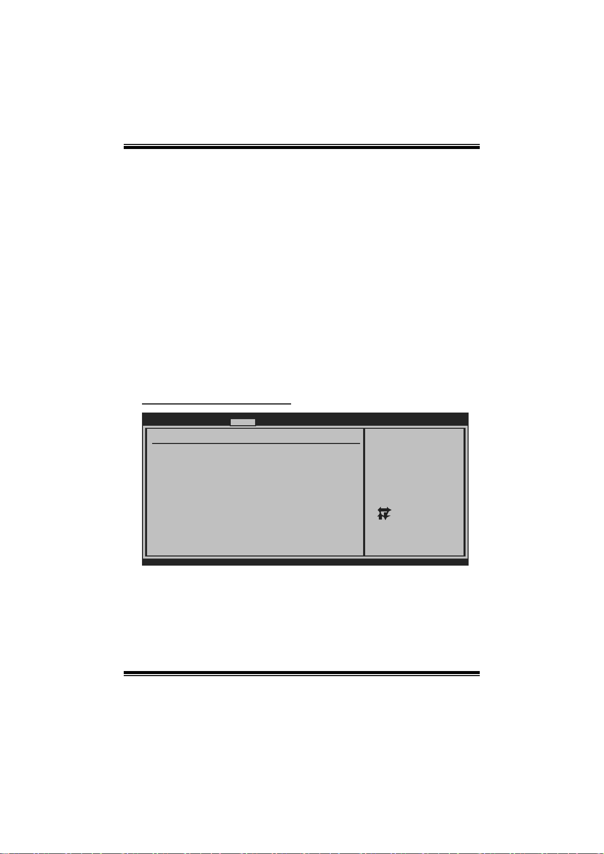
PCIPnP
PCI Express Configuration
Active State Power-Management[Disabled]
BIOS SETUP UTILITY
Enable/Disable
PCI Express L0s and
L1 link power
states.
Select Screen
Select Item
+-
Change Option
F1
General Help
F10
Save and Exit
ESC
Exit
vxx.xx (C)Copyright 1985-200x, American Megatrends, Inc.
Active State Po wer-Manage ment
This item sets the ASPM configuration for the PCI Express devices before the
operating s ystem boots. This function is for OS which does not s upport ASP M.
Options: Disabled (Default) / Enabled
18
Page 20
TA760G M 2+ BIO S Man ual
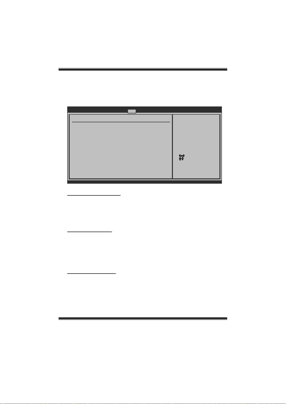
4 Boot Menu
T his menu allows you to setup the system boot options.
Main Advanced PCIPnP Boot Chips et T-Series
Boot Settings Conf iguration
> Boot Device Priority
> Hard Disk Drives
> Removable Drives
> CD/DVD Drives
Quick Boot [Enabled]
Full Screen LOGO Show [Disabled]
AddOn ROM Display Mode [Force BIOS]
Bootup Num-Lock [ON]
Interrupt 19 Capture [Enabled]
Ignore Memory Error Messages [Disabled]
BOOT SUCCESS BEEP [Enabled]
BIOS SETUP UTILITY
Exit
Specifies the
Boot Device
Priority sequence.
Select Screen
Select Item
Go to Sub Screen
Enter
F1
General Help
Save and Exit
F10
Exit
ESC
vxx.xx (C)Copyright 1985-200x, American Megatre nds, Inc.
Boot Device Priority
Items in this sub-menu specify the boot device priority sequence from the available
devices. The number of device items that appears on the screen depends on the
number of devi ces installed in the s ystem.
Options: R emovable / Hard Disk / CDROM / Legacy LAN / Disabled
Hard Disk Drives
T he BIOS will att empt to arrange the hard dis k boot sequence au tomatically. You
can also ch ange th e b o oti n g s equen ce. T he n u mber o f device items t h at ap pear s on
the screen depends on the number of devices installed in the system.
Op t i ons : Pri. M as t er / Pri. Sl ave / Sec. Mas t er / Sec. Sl ave / USB HDD 0 /
USB HDD1 / USB HDD2 / Bootable Add-in C ards
Re mo va ble Dr ives
T he BIOS will att empt to arrange the removabl e drive b oot sequence auto matically.
You can also change the booting sequence. The number of device items that
appears on the screen depends on the number of devic es inst alled in the system .
Options: Floppy Disks / Zip100 / USB-FDD0 / USB-FDD1 / USB-ZIP0 /
USB-ZIP1 / LS120
19
Page 21

TA760G M 2+ BIO S Man ual
CD/DV D Drives
T he BIOS will attempt to arrange the CD/DVD drive boot sequence automati cally.
You can also change the booting sequence. The number of device items that
appears on the screen depends on the number of devic es inst alled in the system .
Op t i ons : Pri. M as t er / Pri. Sl ave / Sec. Mas t er / Sec. Sl ave / USB CDROM0 /
USB CDROM 1
Quick Boot
Enabling this option will cause an abridged version of the Power On Self-Test
(POST) t o execute after you power up the computer.
Options: Enabled (Default) / Disabled
Full Screen LOGO Show
T his item allows you t o enable/disable Ful l Screen LOGO Show f unction.
Options: Disabled (Default) / Enabled
AddOn R OM Dis pl ay Mode
T his item sets the display mode for option R OM.
Op t i ons : Force BIO S (Default) / Keep Cu rren t
Boot u p Num- Lo ck
Selects the NumLock State after the system switched on.
Options: ON (Default) / OFF
Interrupt 19 Capture
When set to Enabled, this item allows the option ROMs to trap interrupt 19.
Options: Enabled (Default) / Disabled
I gnore Memory Error Messages
W hen this item is set to Enabled, BIOS will ignore memory error messages.
Options: Disabled (Default) / Enabled
BOOT SUCCESS BEEP
W hen this item is set to Enabled, BIOS will let user know boot success with beep.
Options: Enabled (Default) / Disabled
20
Page 22
TA760G M 2+ BIO S Man ual
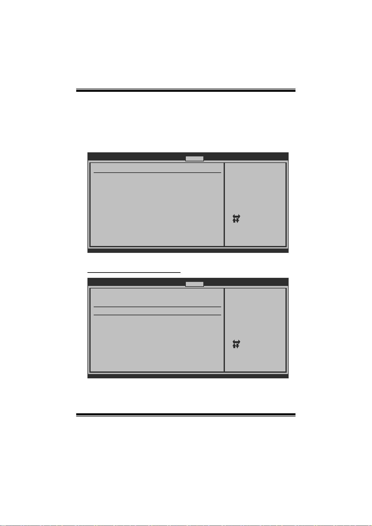
5 C hipset Menu
Thi s su b m en u all o w s you to co nfigu re t he sp eci fic f eat ures of the chip s et i n s talled o n
your system. This chipset manage bus speeds and access to system memory
resources, such as DRAM. It also coordinates communicati ons with the P CI bus.
Main Advanced PCIPnP Boot Chips et T-Series
> SouthBridge Configuration
> RS760 Configuration
> OnBoard Peripherals Configuration
BIOS SETUP UTILITY
Exit
Options for SBAdvanced Chipset Settings
Select Screen
Select Item
Go to Sub Screen
Enter
General Help
F1
Save and Exit
F10
Exit
ESC
vxx.xx (C)Copyright 1985-200x, American Megatre nds, Inc.
S outh B ri dg e C onf igu ra t io n
SouthBridge Chipset Configuration
SB710 CIMx Version : 4.3.0
> SB Azalia Audio Configuration
OHCI HC(Bus 0 Dev 18 Fn 0) [Enabled]
OHCI HC(Bus 0 Dev 18 Fn 1) [Enabled]
EHCI HC(Bus 0 Dev 18 Fn 2) [Enabled]
OHCI HC(Bus 0 Dev 19 Fn 0) [Enabled]
OHCI HC(Bus 0 Dev 19 Fn 1) [Enabled]
EHCI HC(Bus 0 Dev 19 Fn 2) [Enabled]
OHCI HC(Bus 0 Dev 20 Fn 5) [Enabled]
OnChip SATA Channel [Enabled]
OnChip SATA Type [Native IDE]
SATA IDE Combined Mode [Enabled]
Power Saving Features [Disabled]
vxx.xx (C)Copyright 1985-200x, American Megatre nds, Inc.
BIOS SETUP UTILITY
Chipset
21
Options for SB HD Azal
Select Screen
Select Item
Go to Sub Screen
Enter
F1
General Help
F10
Save and Exit
ESC
Exit
Page 23

TA760G M 2+ BIO S Man ual
SB Aza l i a Audi o Configura tion
BIOS SETUP UTILITY
HD Audio Azalia Device [Enabled]
Azalia Clock Gating [Disabled]
vxx.xx (C)Copyright 1985-200x, American Megatre nds, Inc.
Chipset
H D Au d i o A zal i a Device
T his item allows you t o control the HD audi o device.
Options: Enabled (Default) / Auto / Disabled
Azalia Clock Gati ng
Options: Disabled (Default) / Enabled
OHCI HC(Bus 0 Dev 18/19/20 Fn 0/1/5)
Options: Enabled (Default) / Disabled
Options
Auto
Disabled
Enabled
Select Screen
Select Item
Change Option
+-
General Help
F1
Save and Exit
F10
ESC
Exit
EHCI HC(Bus 0 Dev 18/19 Fn 2)
Options: Enabled (Default) / Disabled
OnChip SATA Channel
T his option allows you to enable the on-chip Serial AT A.
Options: Enabled (Default) / Disabled
OnChip S ATA Type
T his option allows you to select the on-chip Serial ATA operation mode.
Options: Native IDE (Default) / RAID / AHCI / Legacy IDE / IDEÆ AHCI
22
Page 24

TA760G M 2+ BIO S Man ual
Option ROM POST Delay
Options: Disabled (Default) / Enabled
SATA IDE Combined M ode
T his option controls the SAT A/PAT A combined mode.
Options: Enabled (Default) / Disabled
Power Sa ving F eat ur es
T his option controls the power saving featur es.
Options: Disabled (Default) / Enabled
RS760 Configuration
BIOS SETUP UTILITY
RS760 Chipset Configuration
RS760 CIMx Version : 4.4.0
> Internal Graphics Configuration
> PCI Express Configuration
Chipset
Internal Graphics Conf
Primary Video Controller [PCI-GFX0-GPP -IGFX]
NB Power Management Features [Auto]
vxx.xx (C)Copyright 1985-200x, American Megatre nds, Inc.
23
Select Screen
Select Item
Enter
Go to Sub Screen
F1
General Help
F10
Save and Exit
ESC
Exit
Page 25

TA760G M 2+ BIO S Man ual
Internal G raphics Configura tion
BIOS SETUP UTILITY
Internal Graphics Configuration
Internal Graphics Mode [UMA]
UMA Frame Buffer Size [Auto]
GFX Engine Clock Override [Disable]
GFX Engine Clock [500]
Surround View [Auto]
FB Location [Above 4G]
AMD 780 HD Audio [Enable]
vxx.xx (C)Copyright 1985-200x, American Megatre nds, Inc.
Chipset
Options
Disable
UMA
Select Screen
Select Item
Change Option
+-
General Help
F1
Save and Exit
F10
ESC
Exit
Int ern al Graphi cs Mode
T his item allows you t o select the memory mode used for internal graphi cs device.
Options: UMA (Default) / Disable
UMA Frame Bu ffer Size
T his item allows you t o choose the UMA frame buffer size for internal graphics.
Options: Auto (Default) / 32M / 64M / 128M / 256M / 512M
GFX En gin e C lock Override
T his item allows you t o control the i nternal GFX engine clock override function.
Options: Disabled (Default) / Enabled
GFX En gin e C lock
T his item allows you t o set t he int ernal GF X engine clock.
Options: 500 (De fault) / Min: 150, Max: 1000
Surro und Vi ew
T his item allows you t o control the S urround View F unction.
Options: Auto (Default)
FB Location
T his item allows you t o set t he FB-DIMM locat ion.
Options: Above 4G (De fault) / Under 4G
24
Page 26
TA760G M 2+ BIO S Man ual
AMD 780 HD Au dio
T his item allows you t o control the northbridge HD azalia (HDMI audio) function.
Options: Enabled (Default) / Disabled
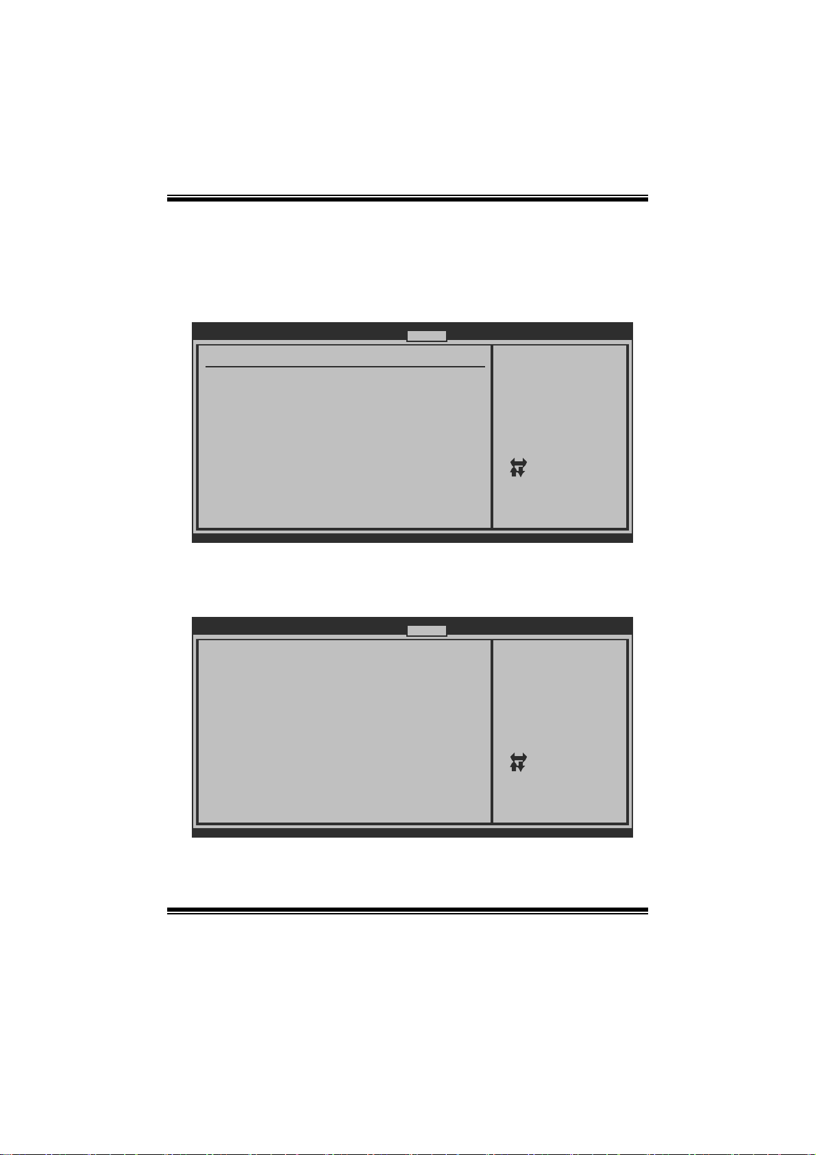
PCI Express Conf ig uration
BIOS SETUP UTILITY
PCI Express Configuration
GPP Slots Power Limit, W [25 ]
> Port #02 Features
> NB-SB Port Features
vxx.xx (C)Copyright 1985-200x, American Megatre nds, Inc.
GPP S l ots Pow er Lim it, W
Options: 25 (De fault) / 0-255
Port #02 Feat ures
BIOS SETUP UTILITY
Gen2 High Speed Mode [Auto]
Link ASPM [Disabled]
Link Width [Auto]
Slot Power Limit, W [75]
Chipset
Chipset
Select Screen
Select Item
Update
Enter
F1
General Help
Save and Exit
F10
Exit
ESC
Auto - RC only
advertize Gen2
capability.
Select Screen
Select Item
Change Option
+F1
General Help
F10
Save and Exit
ESC
Exit
vxx.xx (C)Copyright 1985-200x, American Megatre nds, Inc.
25
Page 27

TA760G M 2+ BIO S Man ual
Gen2 H igh S peed Mode
Options: Disabled (Default) / Auto / Software Initiated / Advertised RC
Link AS PM
Opti ons: Disabled (Default) / L0s / L1 / L0x & L1
Li nk Wi dth
Opti ons: Auto (Default) / x1 / x2 / x4 / x8 / x16
Sl ot Power Lim it, W
Opti ons: 75 (Defaul t) / 0-255
NB-SB Po rt Featu res
BIOS SETU P UTILITY
NB-SB Link ASP M [Disabled]
NP NB-SB VC1 T raffic Support [Disabled]
Link Width [Auto]
Chipset
Options
Disabled
L1
Select Screen
Select Item
Change Option
+-
General Help
F1
Save and Exit
F10
Exit
ESC
vxx .xx (C)Copyright 1985-200x, American Megatrends, Inc.
NB-SB Link ASPM
Options: Disabled (Default) / L1
NP NB-SB V C1 T r affic Sup por t
Options: Disabled (Default) / Enabled
Li nk Wi dth
Options: Auto (Default) / x1 / x2 / x4
Pri mary Vide o Controll er
T his option allows you to select the video controller in charge.
Opt i ons : PCI-GF X0 -GPP -IG FX (Default) / G F X0-GP P-IGF X-PCI /
GPP-GFX0-IGFX-PCI / IGFX-GFX0-GPP-PCI
26
Page 28

TA760G M 2+ BIO S Man ual
NB Power Mana gement Feature s
T his option controls the NB power management function.
Options: Auto (Default) / Disabled
OnBoard Peripherals C onfiguration
BIOS SETU P UTILITY
MAC ID Informa tion
Realtek PCIE N IC [Enable]
Realtek Optio n ROM [Disabled]
Chipset
Enable/Disable
Onboard RTL8111C
PCIE Network
Controller
Select Screen
Select Item
+-
Change Option
F1
General Help
F10
Save and Exit
ESC
Exit
vxx .xx (C)Copyright 1985-200x, American Megatrends, Inc.
MAC ID Information
Thi s area s ho ws t h e M AC ID .
Realtek P CIE NIC
T his option allows you t o control the onboard LAN controller.
Options: Enable (Default) / Disable
Realtek Option ROM
Enable or disable Option ROM for Re altek PCIE Network Controller. T his option
needs to be enabled for P XE boot support.
Options: Disabled (Default) / Enabled
27
Page 29

TA760G M 2+ BIO S Man ual
6 T-Series Menu
T his submenu allows you to change voltage and clock of various devi ces.
(However, we suggest you use the default setting. Changing the voltage and clock
improperly may damage the device.)
Notice
z Beware of that setting inappropriate values in items of this menu may cause
system to malfunction.
Main Advanced PCIPnP Boot Chips et T-Series
T-Series Settings
WARNING: Setting wrong values in below sec tions
may cause system to malfunction.
OverClock Navigator [Normal]
=========== Automate OverClock System ==== =======
Auto OverClock System [V6-Tech Engi ne]
============ Manual OverClock System ===== =======
CPU Overvoltage [StartUp]
Memory Overvoltage [1.95V]
Chipset Overvoltage [1.15V]
HT Overvoltage [1.20V]
CPU Frequency [200]
> CPU FID/VID Control
> DRAM Timing Configuration
> Hyper Transport Configuration
> Memory Configuration
Integrated Memory Test [Disabled]
vxx.xx (C)Copyright 1985-200x, American Megatre nds, Inc.
BIOS SETUP UTILITY
Exit
Options
Normal
Automate OverClock
Manual OverClock
Select Screen
Select Item
Change Option
+-
General Help
F1
Save and Exit
F10
ESC
Exit
OverClock Navigator
OverClock .Navigator is designed for beginne rs in overclock field.
Based on many test and experiments from Biostar Engineer Team, OverClock
Navigator provides 3 default overclock configurations that are able to raise the
system performance.
Options: Normal (Default) / Automate OverClock / Manual OverClock
28
Page 30
TA760G M 2+ BIO S Man ual
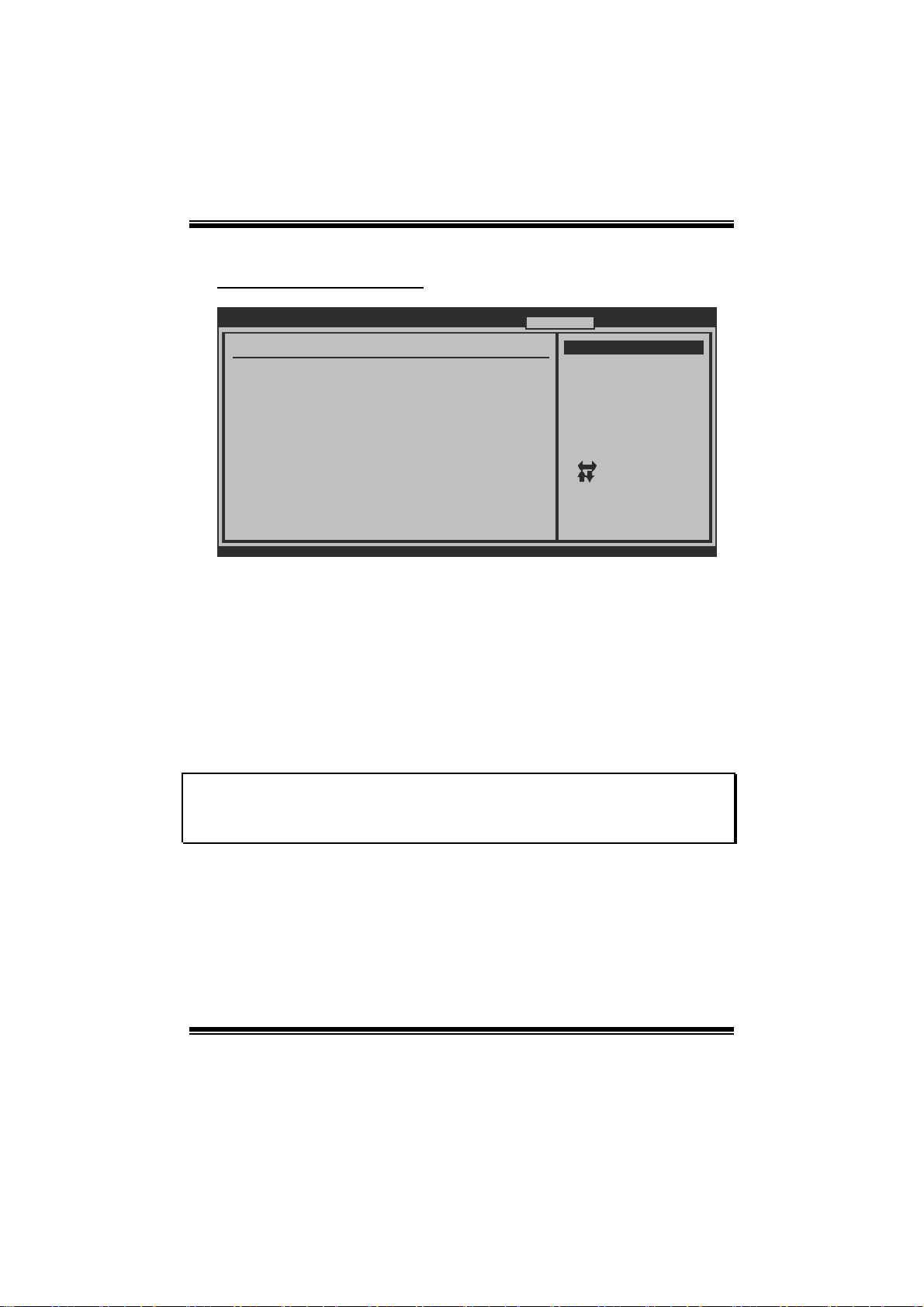
Auto OverCl ock Sy stem
Main Advanced PCIPnP Boot Chips et T-Series
T-Series Settings
WARNING: Setting wrong values in below sec tions
may cause system to malfunction.
OverClock Navigator [Automate Ove rClock]
=========== Automate OverClock System ==== =======
Auto OverClock System [V6-Tech Engi ne]
============ Manual OverClock System ===== =======
CPU Overvoltage [StartUp]
Memory Overvoltage [1.95V]
Chipset Overvoltage [1.15V]
HT Overvoltage [1.20V]
CPU Frequency [200]
> CPU FID/VID Control
> DRAM Timing Configuration
> Hyper Transport Configuration
> Memory Configuration
Integrated Memory Test [Disabled]
vxx.xx (C)Copyright 1985-200x, American Megatre nds, Inc.
BIOS SETUP UTILITY
Options
Normal
Automate OverClock
Manual OverClock
Select Screen
Select Item
Change Option
+-
General Help
F1
Save and Exit
F10
ESC
Exit
Exit
T he Overclock Navig ator provides 3 differ ent engines helping you to overclock your
system . T hese engines will boost your s ystem performan ce to differ ent level.
Options:
V6 Tech Engine
T his engine will make a good over-cl ock perfo rmanc e.
V8 Tech Engine
T his engine will make a better over-cl o ck performance.
V12 Te c h Engine
T his engine will make a best over-clock performance.
Cautio ns:
1. Not every AMD CPU performs the above overclock setting ideall y; the difference may vary
with the installed CPU model.
2. From BET experiment, the Atholon64 FX CPU is not suitable for this A.O.S. feature.
29
Page 31
TA760G M 2+ BIO S Man ual
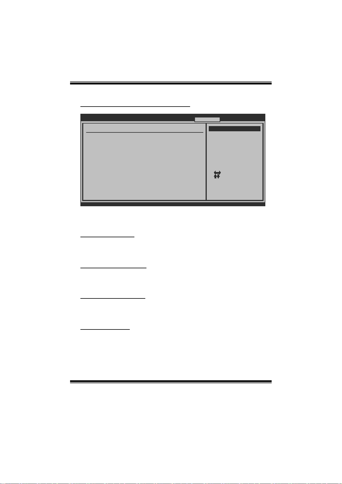
Manual Overclock S ystem (M.O .S. )
Main Advanced PCIPnP Boot Chips et T-Series
T-Series Settings
WARNING: Setting wrong values in below sec tions
may cause system to malfunction.
OverClock Navigator [Manual OverC lock]
=========== Automate OverClock System ==== =======
Auto OverClock System [V6-Tech Engi ne]
============ Manual OverClock System ===== =======
CPU Overvoltage [StartUp]
Memory Overvoltage [1.95V]
Chipset Overvoltage [1.15V]
HT Overvoltage [1.20V]
CPU Frequency [200]
> CPU FID/VID Control
> DRAM Timing Configuration
> Hyper Transport Configuration
> Memory Configuration
Integrated Memory Test [Disabled]
vxx.xx (C)Copyright 1985-200x, American Megatre nds, Inc.
BIOS SETUP UTILITY
Options
Normal
Automate OverClock
Manual OverClock
Select Screen
Select Item
Change Option
+-
General Help
F1
Save and Exit
F10
ESC
Exit
Exit
MOS is designed for expe rienced overclock users.
It allows users to customize personal overclock setti ng.
CPU Overvoltage
T his item allows you t o select CPU Voltage Control.
Options: S tartUp (Default) / +0.10V / +0. 20V / +0.30V
Memory Overvo ltag e
T his item allows you t o select DDR Voltage Control.
Options: 1. 95V (Default ) / 2.05V / 2.15V / 2.25V / 2. 35V / 2.45V / 2.55V / 2. 65V
Chipset O verv oltage
T his item allows you t o select NB /SB Voltage Control.
Options: 1. 15V (Default ) / 1.25V / 1.35V / 1.45V
HT Overvoltage
T his item allows you t o select HT Volt age Control.
Options: 1. 20V (Default ) / 1.30V / 1.40V / 1.50V
30
Page 32

TA760G M 2+ BIO S Man ual
CPU Fr e que nc y
T his item allows you t o select the CPU Frequency.
Options: 200 (M Hz) (Default) / 200-600
CPU FI D/V ID Co ntrol
BIOS SETUP UTILITY
CPU FID/VID Control
Custom P-States [Disabled]
Core FID [x11.5 2300MH z]
Core DID [Divided by 1 ]
Core VID [1.2500 V]
NB FID [2000 Mhz]
vxx.xx (C)Copyright 1985-200x, American Megatre nds, Inc.
T-Series
Options
+F1
F10
ESC
Select Screen
Select Item
Change Option
General Help
Save and Exit
Exit
Custom P-States (for AM2+ CPU)
T his item allows you t o select the P -States controll ing.
Options: Disabled (Default) / Enabled
Core FID (for AM2 + CPU)
T his item allows you t o select the Ratio/ Frequency of AM2+ C P U.
Options: x8.0 1600MHz ~ x31.5 6300MHz (Diffe red by CP U)
Core DID (for AM2 + CPU)
Options: Divided by 1 (Default) / Divided by 2 / Divided by 4 / Divided by 8 /
Divi ded by 16
Core VI D (for AM2+ CPU)
T his function allows you to adjust the voltage of CPU.
Options: 0. 0125V ~ 1.5500V (Differ ed from CPU).
31
Page 33
TA760G M 2+ BIO S Man ual
NB FID (for AM2+ CPU)
T his item allows you t o select the F requency o f NB chip.
Options: 2000MHz (Default) / 800MHz ~ 7000MHz
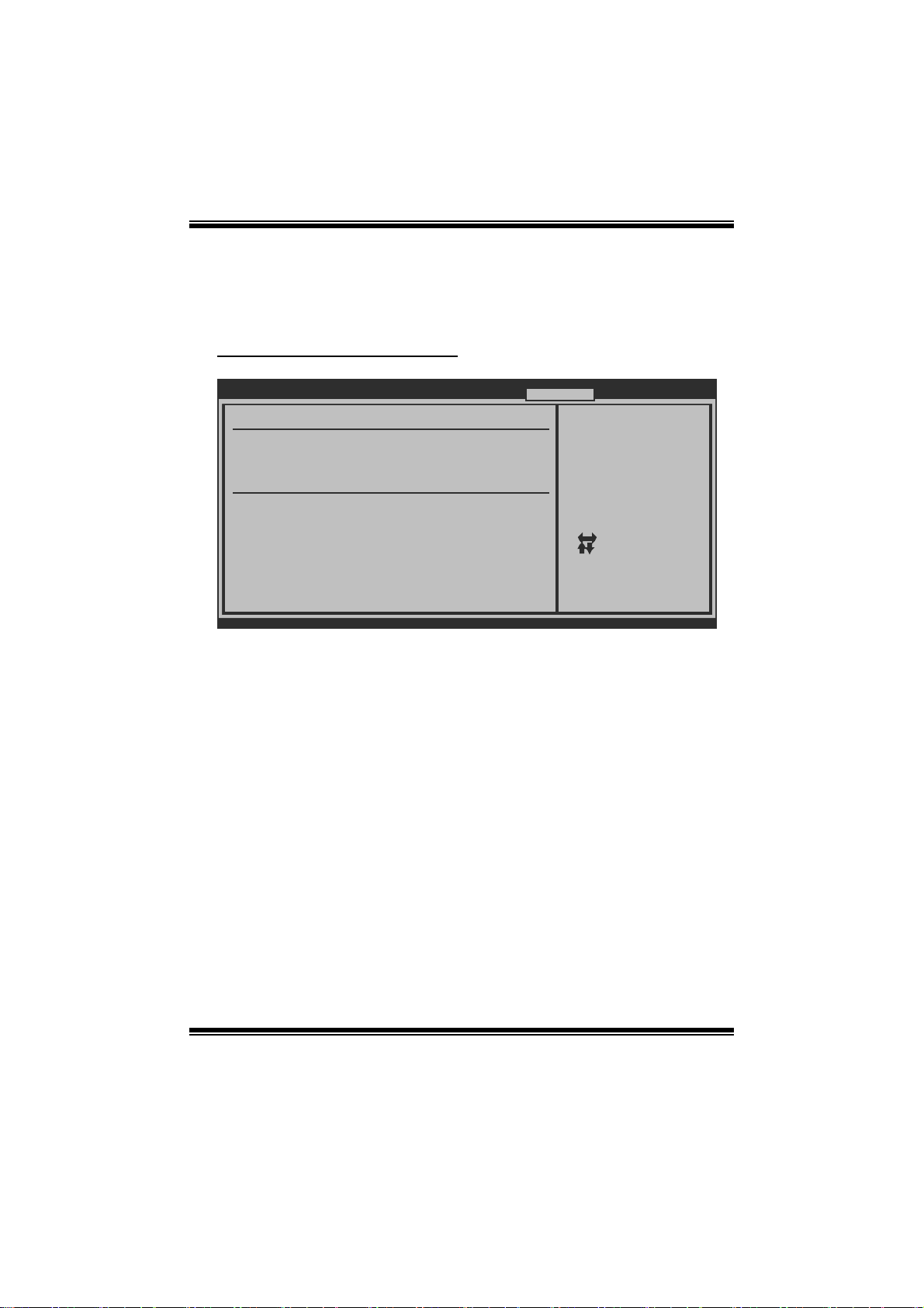
DRA M Tim i ng Configuration
BIOS SETUP UTILITY
DRAM Timing Config uration
Memory Clock Mode [Auto]
Memclock Value [DDR2-400]
Memory CLK :
DRAM Timing Mode [Auto]
Memory CLK :
CAS Latency(Tcl) :
RAS/CAS Delay(Trcd) :
Row Precharge Time(Trp):
Min Active RAS(Tras) :
RAS/RAS Delay(Trrd) :
Row Cycle (Trc) :
vxx.xx (C)Copyright 1985-200x, American Megatre nds, Inc.
T-Series
Select the DRAM
Frequency programming
method. If Auto,
the DRAM speed will
be based on SPDs.
If Limit, the DRAM spe
will not exceed the
specified value. If
Manual, the DRAM speed
specified will be
programmed regardless.
Select Screen
Select Item
Change Option
+-
General Help
F1
Save and Exit
F10
Exit
ESC
Memory Clock Mode
T his item allows you t o control the M emory Clock.
Options: Auto (Default) / Limit / Manual
Me mclock Va lue
T his item allows you t o set t he Memory Clock.
Options: DDR2-400 (Default) / DDR2-533 / DDR 2-667 / DDR 2-800 / DDR2-1066
D RAM Timing Mode
T his item allows you to choose to manually or automatically regul ate the DRAM
Timing.
Options: Auto (Default) / DCT0 / DCT1(for AM2+ CP U) / B oth(for AM2+ CPU)
CAS La te ncy (CL)
Options: Auto (Default) / 3~6 CLK / 7CLK DH_Only
32
Page 34

TA760G M 2+ BIO S Man ual
2T Command
Options: Auto (Default) / 1T / 2T
TRCD
Options: Auto (Default) / 3~6 CLK
TRP
Options: Auto (Default) / 3~6 CLK
tRT P
Options: Auto (Default) / 2-4 CLK / 3-5 C LK
TRAS
Options: Auto (Default) / 5~18 CLK
TRC
Options: Auto (Default) / 11~26 CLK
tWR
Options: Auto (Default) / 3~6 CLK
TRRD
Options: Auto (Default) / 2~5 CLK
tWT R
Options: Auto (Default) / 1~3 CLK
tRFC0 / tRFC1 / tR FC2 / tRFC3
Options: Auto (Default) / 75ns / 105ns / 127.5ns / 195ns / 327.5ns
33
Page 35
TA760G M 2+ BIO S Man ual
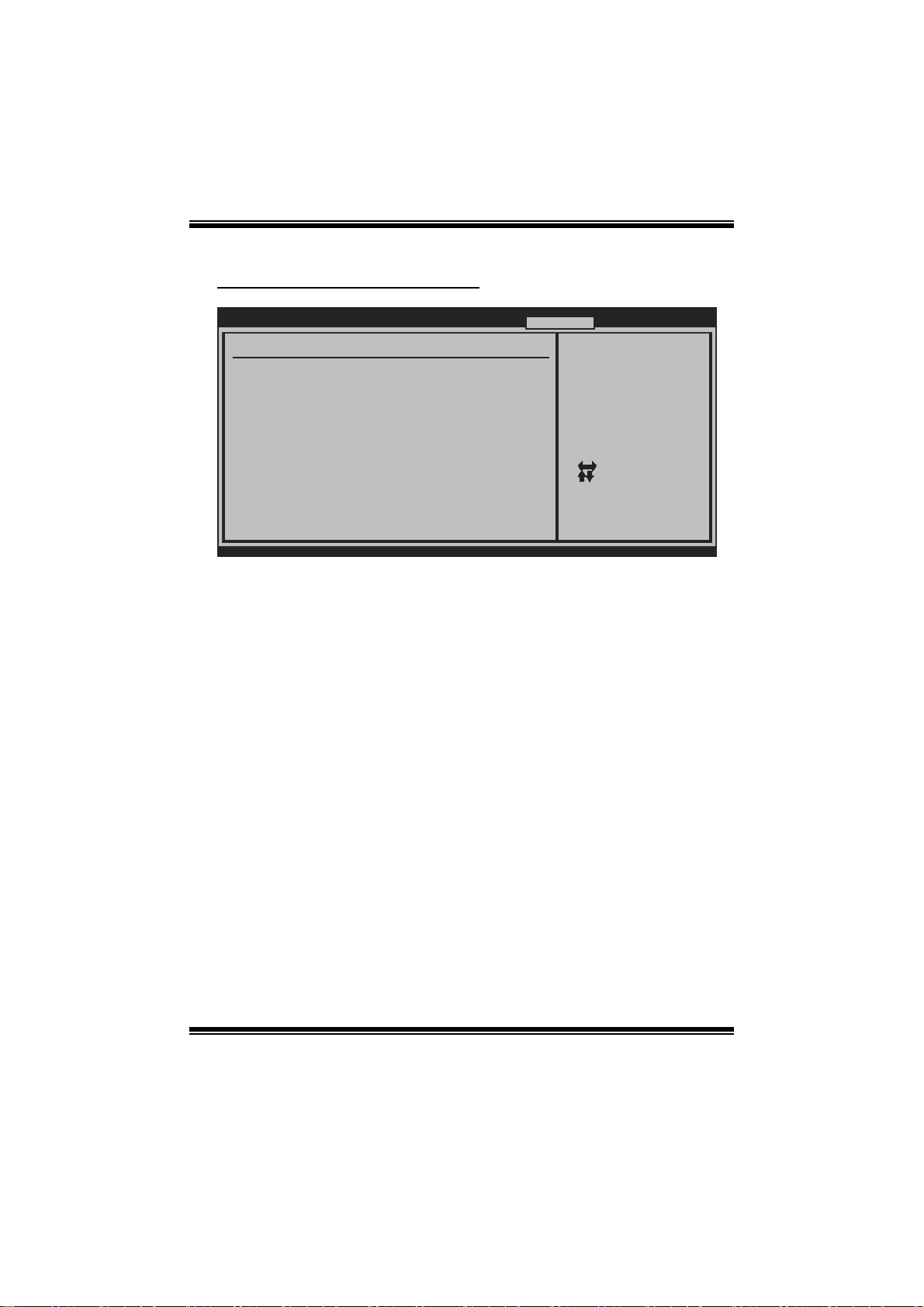
Hyper Transport Configuration
BIOS SETU P UTILITY
Hyper Transpor t Configuration
NODE0:PCI-X2 HT Link
Link Speed [Auto]
Link Width [Auto]
vxx .xx (C)Copyright 1985-200x, American Megatrends, Inc.
T-Series
The Hypertransport
link will run at this
speed if it is slower
than or equal to the
system clock and the
board is capable.
Select Screen
Select Item
+-
Change Option
F1
General Help
F10
Save and Exit
ESC
Exit
Link Speed
Options: Auto (Default) / 200MHz / 400MHz / 600MHz / 800MHz / 1GHz /
1. 2GHz / 1.4GHz / 1. 6GHz / 1. 8GHz
Link Width
Options: Auto (Default) / 4 Bit / 8 Bit / 16 Bit
34
Page 36
TA760G M 2+ BIO S Man ual
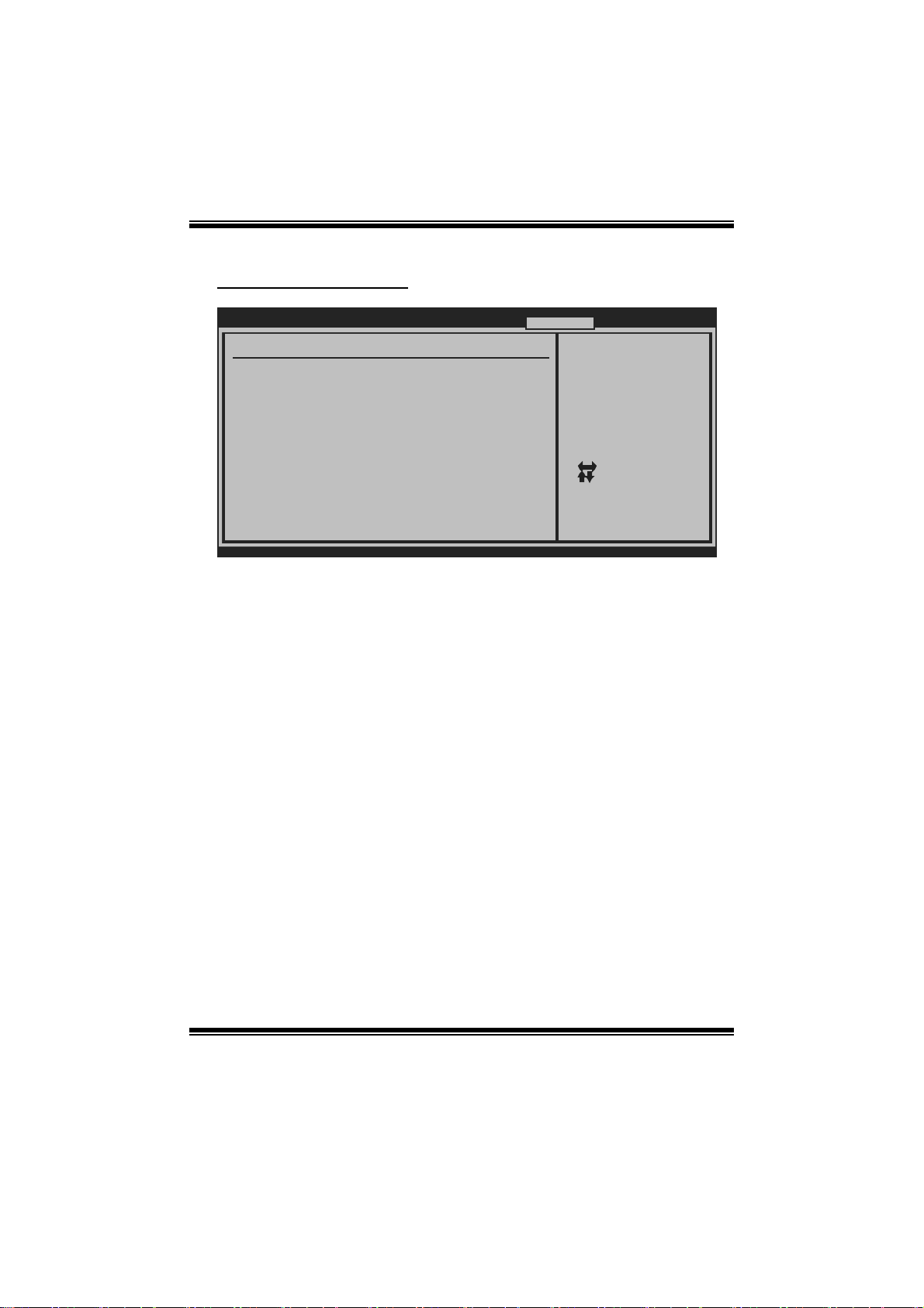
Memory Configu ration
BIOS SETU P UTILITY
Memory Configu ration
Bank Interleav ing [Auto]
Channel Interl eaving [XOR of Address bit]
Enable Clock t o All DIMMs [Disabled]
MemClk Tristat e C3/ATLVID [Disabled]
Memory Hole Re mapping [Enabled]
DCT Unganged M ode [Always]
Power Down Ena ble [Enabled]
Power Down M ode [Channel]
> ECC Configur ation
vxx .xx (C)Copyright 1985-200x, American Megatrends, Inc.
T-Series
Enable Bank Memory
Interleaving
+F1
F10
ESC
Select Screen
Select Item
Change Option
General Help
Save and Exit
Exit
Bank Interleaving
Bank Interleaving is an advanced chipset technique used to improve memory
performance. Memory interleaving increases bandwidth by allowing simultaneous
acc ess t o m o re than o ne pi ece o f m em o ry.
Options: Auto (Default) / Disabled
Channel Interleaving
T his item allows you t o control the DDR2 dual-channel funct ion.
Options: XOR of Address bits [20:16, 6] (Default) / XOR of Address bits
[20:16, 9] / Address bit s 6 / Address bits 12 / Disabled
Enable Cl ock to Al l DI MMs
This item determines whether the BIOS should actively reduce EMI
(Electromagnetic Interference) and reduce power consumption by turning off
unoccupied or inactive DIMM slots.
Options: Disabled (Default) / Enabled
35
Page 37

TA760G M 2+ BIO S Man ual
Me mClk Tristate C3/ATLVID
T his item enables or disables the MemClk T ristate function in C3 Mode.
Options: Disabled (Default) / Enabled
M emory Hole Re m apping
This item allows you to enable or disable the remapping of the overlapped PCI
memory above the total physical memory. Only 64-bit OS supports t his function.
Options: Enabled (Default) / Disabled
DC T Unganged Mode
This item controls the DRAM controller ganged (128bit*1) / unganged (64bit*2)
dual-channel operation mode. If two DRAM modules with different size are
installed, using unganged mode can still make it run in dual-channel operation.
Options: Always (Default) / Auto
Power Down Enable
T his item controls the DR AM power down function.
Options: Enabled (Default) / Disabled
Power Dow n Mode
T his item allows you t o select the DRAM power down mode.
Options: C hannel (Default) / CS
36
Page 38
TA760G M 2+ BIO S Man ual
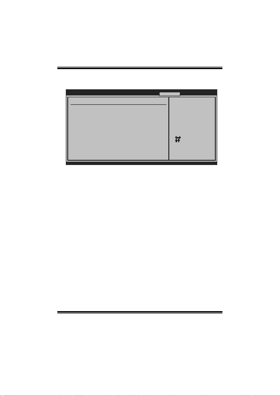
ECC Configuration
BIOS SETU P UTILITY
ECC Configurat ion
ECC Mode [Disabled]
DRAM ECC Ena ble [Disabled]
DRAM SCRUB R EDIRECT [Disabled]
4-Bit ECC Mo de [Disabled]
DRAM BG Scru b [Disabled]
Data Cache B G Scrub [Disabled]
L2 Cache BG Scrub [Disabled]
L3 Cache BG Scrub [Disabled]
vxx .xx (C)Copyright 1985-200x, American Megatrends, Inc.
T-Series
Set the level of ECC
protection. Note: The
Super ECC mode
dynamically sets the
DRAM scrub rate so
all of memory is
scrubbed in 8 hours.
Select Screen
Select Item
+-
Change Option
F1
General Help
F10
Save and Exit
ESC
Exit
ECC M o de
T his item allows you t o select the DRAM EC C Mode.
Options: Disabl ed (De fault) / B asic / Good / Super / M ax / User
DRAM ECC Ena ble d
Options: Disabled (Default) / Enabled
DR AM Scrub R ed i r ect
Options: Disabled (Default) / Enabled
4-bit E CC Mode
Options: Disabled (Default) / Enabled
DRAM BG Scrub/Data Cache BG Scrub/L2 Cache BG Scrub/L3 Cache BG Scrub
Options: Disabl ed (De fault) / 40ns / 80ns / 160ns / 320ns / 640ns / 1.28us / 2.56us /
5.12us / 10.2us / 20.5us / 41.0us / 81.9us / 163.8us / 327.7us / 655.4us /
1.31ms / 2.62ms / 5.24ms / 10. 49m s / 20.97m s / 42.00m s / 84.00ms
37
Page 39
TA760G M 2+ BIO S Man ual
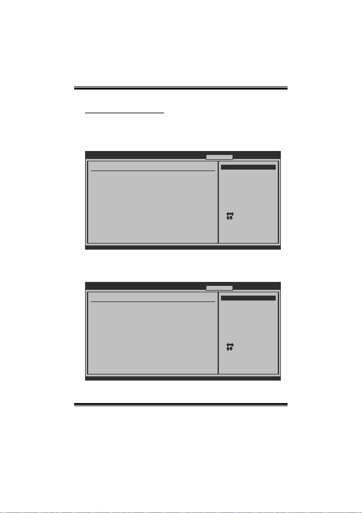
I nte grated Memory Test
Integrated Memory Test allows users to test memory module compatibilities without
additi onal device or softw are.
Step 1:
Thi s i t em is disabl ed o n default ; chan g e it t o “En able” t o precede mem o ry t est.
Main Advanced PCIPnP Boot Chips et T-Series
T-Series Settings
WARNING: Setting wrong values in below sec tions
may cause system to malfunction.
OverClock Navigator [Normal]
=========== Automate OverClock System ==== =======
Auto OverClock System [V6-Tech Engi ne]
============ Manual OverClock System ===== =======
CPU Overvoltage [StartUp]
Memory Overvoltage [1.95V]
Chipset Overvoltage [1.15V]
HT Overvoltage [1.20V]
CPU Frequency [200]
> CPU FID/VID Control
> DRAM Timing Configuration
> Hyper Transport Configuration
> Memory Configuration
Integrated Memory Test [Enabled]
vxx.xx (C)Copyright 1985-200x, American Megatre nds, Inc.
BIOS SETUP UTILITY
Exit
Options
Normal
Automate OverClock
Manual OverClock
Select Screen
Select Item
Change Option
+-
General Help
F1
Save and Exit
F10
ESC
Exit
Step 2:
When the process is done, change the setting back from “Enabled” to “Disabled” to
complete the test.
Main Advanced PCIPnP Boot Chips et T-Series
T-Series Settings
WARNING: Setting wrong values in below sec tions
may cause system to malfunction.
OverClock Navigator [Normal]
=========== Automate OverClock System ==== =======
Auto OverClock System [V6-Tech Engi ne]
============ Manual OverClock System ===== =======
CPU Overvoltage [StartUp]
Memory Overvoltage [1.95V]
Chipset Overvoltage [1.15V]
HT Overvoltage [1.20V]
CPU Frequency [200]
> CPU FID/VID Control
> DRAM Timing Configuration
> Hyper Transport Configuration
> Memory Configuration
Integrated Memory Test [Disabled]
vxx.xx (C)Copyright 1985-200x, American Megatre nds, Inc.
BIOS SETUP UTILITY
38
Options
Normal
Automate OverClock
Manual OverClock
Select Screen
Select Item
+-
Change Option
F1
General Help
F10
Save and Exit
ESC
Exit
Exit
Page 40
TA760G M 2+ BIO S Man ual
7 Exit Menu
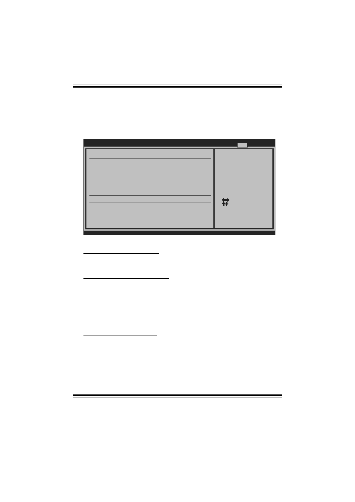
This menu allows you to load the optimal default settings, and save or discard the
changes to the BIOS items.
Main Advanced PCIPnP Boot Chipset T-Series
Exit Options
Save Changes a nd Exit
Discard Change s and Exit
Discard Change s
Load Optimal D efaults
CMOS Backup Fu nction
BIOS SETU P UTILITY
Exit
Exit system setup
after saving the
changes.
F10 key can be used
for this operation.
Security Setti ngs
> Security
vxx .xx (C)Copyright 1985-200x, American Megatrends, Inc.
Select Screen
Select Item
Go to Sub Screen
Enter
General Help
F1
Save and Exit
F10
Exit
ESC
Save Changes and Exit
Save all confi gur ation changes to C MOS R AM and exit setup.
Di scard Changes and Exit
Abandon all changes made during the current session and exit setup.
Di scard Changes
Abandon all changes made during the current session and restore the previously
saved values.
Load Optim al De faults
This selection allows you to reload the BIOS when problem occurs during system
booting sequence. These configurations are factory settings optimized for this
system.
39
Page 41
TA760G M 2+ BIO S Man ual
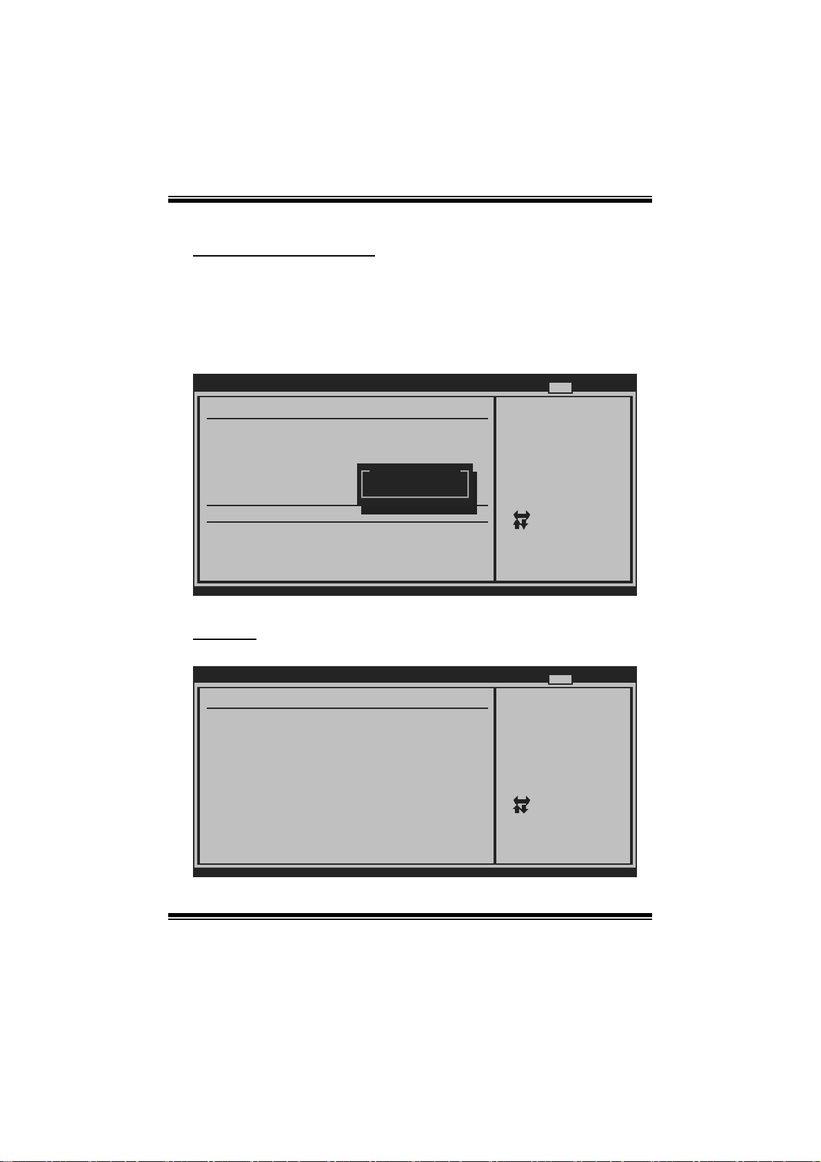
CMOS Ba ckup Func tion
It allows users to save different CMOS settings into BIOS-ROM and reload any
saved CMOS setting for customizing system configurations.
Moreover, users are able to save an ideal overclock setting during overclock
operation.
There are 10 s et s o f re cord ad d res ses i n t o t al , an d us ers are ab l e t o nam e t h e CM OS
dat a acco rd i n g to p ers onal preferenc e.
Main Advanced PCIPnP Boot Chipset T-Series
Exit Options
Save Changes a nd Exit
Discard Change s and Exit
Discard Change s
Load Optimal D efaults
CMOS Backup Fu nction
Security Setti ngs
> Security
vxx .xx (C)Copyright 1985-200x, American Megatrends, Inc.
Security
BIOS SETU P UTILITY
CMOS Backup Func
CMOS Data Reload
CMOS Data
Save
Exit
Select Screen
Select Item
Go to Sub Screen
Enter
General Help
F1
Save and Exit
F10
Exit
ESC
T his sub-menu allows you to provide/revise supervi sor and user password.
BIOS SETUP U TILITY
Security Settings
Supervisor Password :Not Installed
User Password :Not Installed
Change Supervisor Password
Change User Password
Boot Sector Virus Protection [Disabled]
Install or Change the
password.
Exit
Select Screen
Select Item
Change
Enter
General Help
F1
Save and Exit
F10
Exit
ESC
vxx.xx (C)Copyright 1985-200x, American Megatrends, Inc.
40
Page 42

TA760G M 2+ BIO S Man ual
Change Supervi sor P assword
Setting the supervisor password will prohibit everyone except the supe rvisor from
making changes using the CMOS Setup Utility. You will be prompted with to enter a
password.
Cha nge Us er Password
If the Supervisor Password is not set, then the User Password will function in the
same way as the Supervisor Password. If the Supervisor Password is set and the User
Password is set, the “User” will only be able to view configurations but will not be
abl e to ch an g e t hem.
Boot S e ctor V i r us Protection
T his option allows you to choose the VIRUS Warning feature that is used to protect
the IDE Hard Disk boot sector. If this function is enabled and an attempt is made to
write to the boot sector, BIOS will display a warning message on the screen and
sound an alarm beep.
Options: Disabled (Default) / Enabled
41
 Loading...