

Page 1

M
i
M
M
7
7
V
V
I
I
P
P
P
I
V
7
FCC S t a tement an d Co pyri ght
This equipm ent has been tested and f ound to com ply with the limits of a
Class B digital devic e, purs uant to Part 15 of t he FCC Rules. These limits
are designed to provide reasonable protection against harmful interf erenc e
in a residential installation. This equipment generates, uses and can
radiate radio frequency energy and, if not installed and used in
acc ordance wit h the instruct ions, may cause harmf ul int erf erence to radio
comm unicat ions. There is no guarantee that interference will no t occur in a
partic ular ins t allat ion.
The vendor makes no representations or warranties with respect to the
contents here of and specially disclaims any implied warranties of
merc hantability or f it ness for any purpose. Further t he vendor reserv es t he
right t o rev ise t his publicat ion and t o mak e changes to the c ontent s here of
without obligation to notif y any party beforehand.
Duplication of this publication, in part or in whole is not allowed without
first obtaining the vendor’s approval in writing.
The cont ent of this user’s is subject to be changed without notice and we
will not be respons ible f or any mistak es f ound in this user’s manual. All the
brand and product names are tradem arks of their respective companies.
Page 2

C
n
o
C
n
o
C
ENGLISH.............................................................................................1
M7VIP Features................................................................................................................................1
Package con tents ...........................................................................................................................3
Layout of M7VIP (For Version 1.0)..............................................................................................4
Layout of M7VIP (For Version 1.1 and above) .........................................................................5
CPU Installation............................................... ................................................................................6
DDR DIMM Modules: DIMM1-2-3.................................. .................. .................. .................. .........7
Ju mpers, Head ers, Connectors & Slots ........................................................ ...........................9
s
t
n
e
t
s
t
n
e
t
s
t
n
e
t
n
o
ESPAÑOL..........................................................................................1 5
Carac terísticas del M7VIP............................................... ............................................................1 5
Contenido del Paquete................................. ...............................................................................16
Disposición del M7VIP (Para Ve rsión 1.0)................. .............................................................17
Disposición del M7VIP (Para Ve rsiones 1 .1 en adelante) ..................................................18
Ins talación de la CPU.................. .................................................................................................18
Ins talación de la CPU.................. .................................................................................................19
Módulos DDR DIMM: DIMM1-2-3...............................................................................................20
Pue ntes, Cabezales, Conectores y Ranuras .........................................................................22
SERIAL ATA CHIP - FASTTRAK 376...................................................2 8
Step 1: Installing the Hard Drives.................................................................... .........................28
Step 2: Auto Setup Fas tBuild™ Configuration Utilit y.........................................................29
Step 3: Installing Software Drivers............ ...............................................................................3 5
Step 4: Install PAM Utilit y ...........................................................................................................42
Using FastBuild™ Configuration Utilit y.. ...............................................................................48
WARPSPEEDER................................................................................57
Introduction....................................................................................................................................57
System Requirement .................. .......................................................................................... ... ....5 8
Ins tallation ......................................................................................................................................58
Usa ge ...............................................................................................................................................59
TROU BLE SHOOTING .......................................................................68
SOL UC IÓN DE PRO B LE MA S ...................... ............ ........................ ...31
ii
Page 3

M
M
M
o
b
r
e
h
t
o
d
r
a
o
D
r
c
s
e
r
c
s
e
D
d
r
a
o
b
r
e
h
t
n
o
i
t
p
i
n
o
i
t
p
i
n
o
i
t
p
i
r
c
s
e
D
d
r
a
o
b
r
e
h
t
o
English
M7 VIP Feature s
Us e VIA VT8367 (KT333) / VT8235 Chipset, Winbond W83697H F.
Cont ains on board I/O facilities, which include two serial port s, a parallel
port, a PS/2 mous e port, a PS/ 2 keyboard port, audio ports, U SB ports and
a game port.
Supports Single Socket-A for an AMD Athlon/ Duron Family processor,
running at 200 or 266 MHz Front Side Bus frequency . (For Version 1.0)
Supports Single Socket-A for an AMD Athlon/ Duron Family processor,
running at 200, 266 or 333 MH z Front Side Bus frequency. (For Vers ion 1.1
and abov e)
The AMD Athlon system bus supports the 200/266 MHz high-speed,
split -transaction AMD Athlon system bus interface. (For Version 1.0)
The AMD Athlon system bus supports the 200/266/333 MHz high-speed,
split-transaction AMD Athlon system bus interface. (For Version 1.1 and
above)
Supports Ultra DMA 33/66/100/133 Bus Master Modes, PIO Mode 4,
Master Mode, and high performance hard disk driv es.
Support s U SB2. 0 High Speed Dev ic e, 2 ports in rear panel and 4 ports in
front panel.
The VT8367 (KT333) s y stem c ontroller is des igned t o support 200/266/ 333
MH z DDR SD RA M DIMMs.
Suppo rt a maxim un memory size up tp 3GB.
Support s one CN R Slot (Ty pe B only), one AGP Slot (AGP 4X), and fiv e
32-bit PCI Bus slots.
Complies with PC ATX form f actor specifications.
Support s popular operating systems s uch as W indows N T, Windows 98SE,
Windows 2000, W indows ME, Windows XP and LINU X.
CPU over temperature protection.
1
Page 4

M
M
M
Int el® AC ’97 2.2 compatible. High S/N ratio m eets PC 99 requirements.
Line-in phonejack and Mic-in jack s hare with rear Audio out f or 6 channels
Audio.
Support f ront audio pin head functions.
Suppo rt wake u p from USB ke yboar d/ mouse .
Support 3 ports f irewire 1394 function (Optional).
Support 2 serials and 1 parallel Serial ATA and R aid functions (Optional).
Support ov er speed/ voltage function (Optional).
1394 Feat ures:
OHCI Compliant Programming Interface .
Com pliant with 1394 Open H CI Specif icat ions v1.0 and v 1. 1.
Des cript or based isoc hronous and asy nc hronous DMA c hannels for
receive/ transmit packets.
32-Bit Power-Managed PCI Bus I nterf ace
Compliant with PCI specification v2.2.
Int egrated 400 Mbit 3-Port PHY.
Supports prov is ions of I EEE 1394-1995 St andard.
Fully interoperable with IEEE Std 1394-1995 devic es.
b
r
e
h
t
o
b
r
e
h
t
o
d
r
a
o
d
r
a
o
r
c
s
e
D
r
c
s
e
D
n
o
i
t
p
i
n
o
i
t
p
i
n
o
i
t
p
i
r
c
s
e
D
d
r
a
o
b
r
e
h
t
o
PDC20376 Serial ATA- Raid Features:
Single chip, high perf orm ance SATA-R AID implementation.
Built in 2 c hannels SATA PHY, whic h satisfy SATA 1.0 s pecificat ion
and can transfer data with 1. 5GHz s peed.
Additional one parallel ATA interface which satisfy ATA 133
specification.
Bus mastering design takes full advantage of multi-tasking,
multi-threading operating systems and greatly improves
performance.
Prov ides adv ance chained packet c omm ands for independent ATA
operations.
2
Page 5

M
M
M
Compatible with the latest PCI IDE, ATA 7 and enhanced IDE
specifications.
Supports ATA proprosal PI O Mode 0, 1, 2, 3, 4, U lt ra D MA Mode 0,
1, 2, 3, 4, 5, 6. The ID E drive transf er rat e is capable of up to 150
MB/sec.
Autom atically detects whet her or not the c able is s uitable for mode
3, 4, 5, 6 of Ultra D MA.
Com pliance with the PC2000, WHQL hardware requirements.
b
r
e
h
t
o
b
r
e
h
t
o
d
r
a
o
d
r
a
o
r
c
s
e
D
r
c
s
e
D
n
o
i
t
p
i
n
o
i
t
p
i
n
o
i
t
p
i
r
c
s
e
D
d
r
a
o
b
r
e
h
t
o
Package contents
HDD Cable X 1, F DD Cable X 1, Fully Setup Driv er CD X 1
Flash Memor y Writer for BIOS update X 1
USB Cable X 2 (Optional)
Rear I/O Panel for ATX Case X 1 (Optional)
3
Page 6
M
(
)
M
M
o
b
r
e
h
t
o
d
r
a
o
D
r
c
s
e
r
c
s
e
D
d
r
a
o
b
r
e
h
t
n
o
i
t
p
i
n
o
i
t
p
i
n
o
i
t
p
i
r
c
s
e
D
d
r
a
o
b
r
e
h
t
o
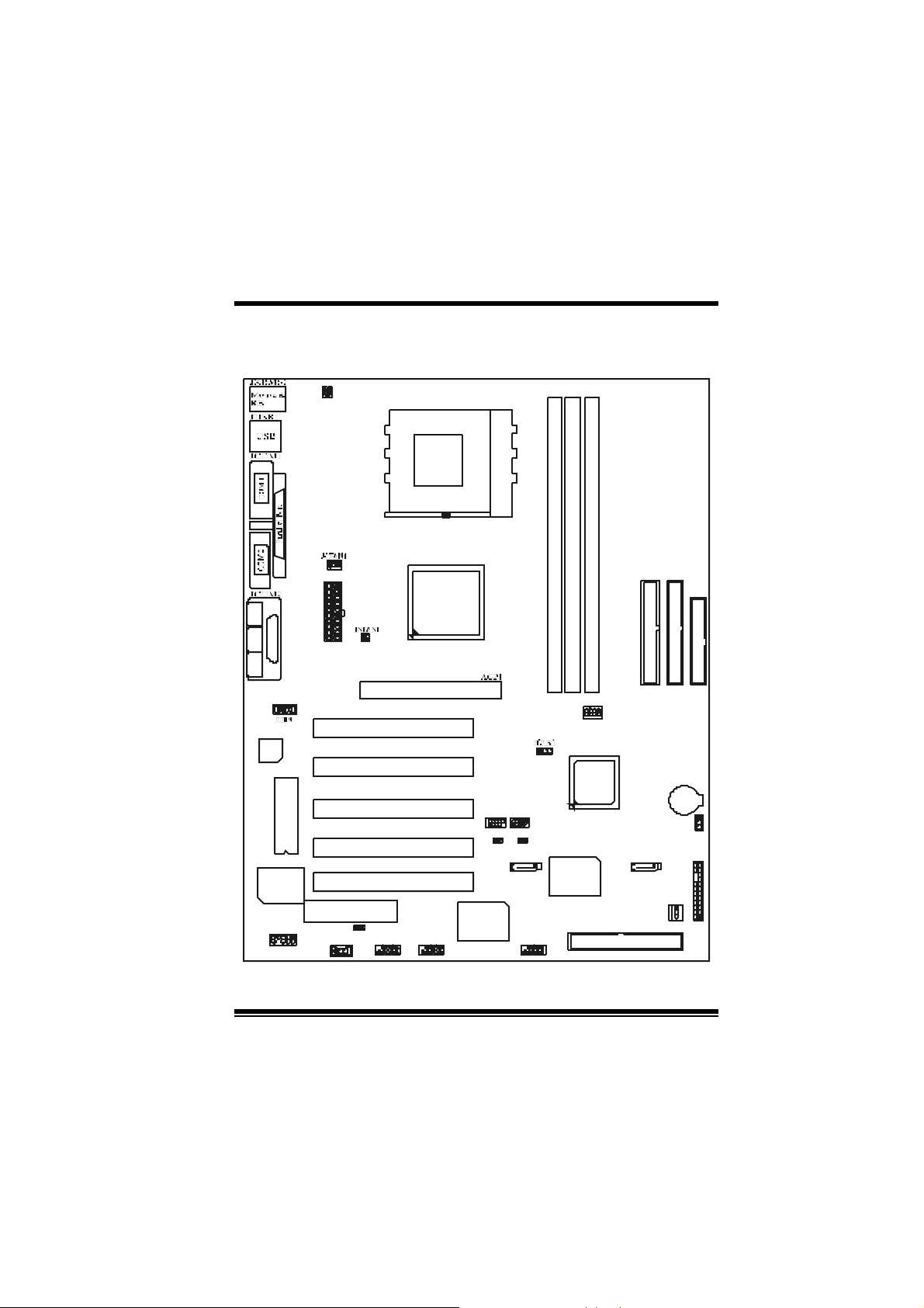
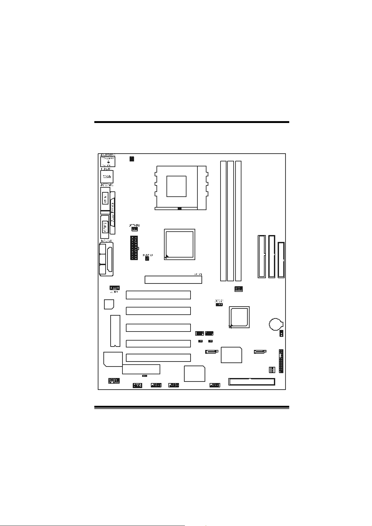
Layout of M7VI P (For Version 1.0)
1
1
JUSB V1
JKBV1
CPU
Socket A
DIMM 1
DIMM3
1
JATXPWR1
SP-OUTM IC -IN LI NE-IN
1
GAM E Port
VT8367
KT333
DIMM2
JGAME1
CMI9739
Winbond
I /O
JAUDIO1
1
BIOS
CNR SLOT
JWOL 1
1
1
1
PCI SLOT
PCI SLOT
PCI SLOT
PCI SLOT
PCI SLOT
JCODECSEL1
J1394A1
9
10
A GP SLOT
CNR1
J1394B1
1
9
2
10
127
IDE1 IDE2 FDD1
BAT1
JCM OS1
JPANEL1
JSATA2JSATA1
JSFAN1
1
1
2324
12
J DIMMVOLT 1
1
JUSB 2
Controller
1
2
8
VT8235
Serials
ATA
RAID1
PCI1
PCI2
PCI3
JUSB1
10
10
129
JUSBV2
1394
CHIP
129
1
1
JUSBV3
J1394C1
9
10
PCI4
PCI5
1
2
4
Page 7
M
(
)
M
M
o
b
r
e
h
t
o
d
r
a
o
D
r
c
s
e
r
c
s
e
D
d
r
a
o
b
r
e
h
t
n
o
i
t
p
i
n
o
i
t
p
i
n
o
i
t
p
i
r
c
s
e
D
d
r
a
o
b
r
e
h
t
o
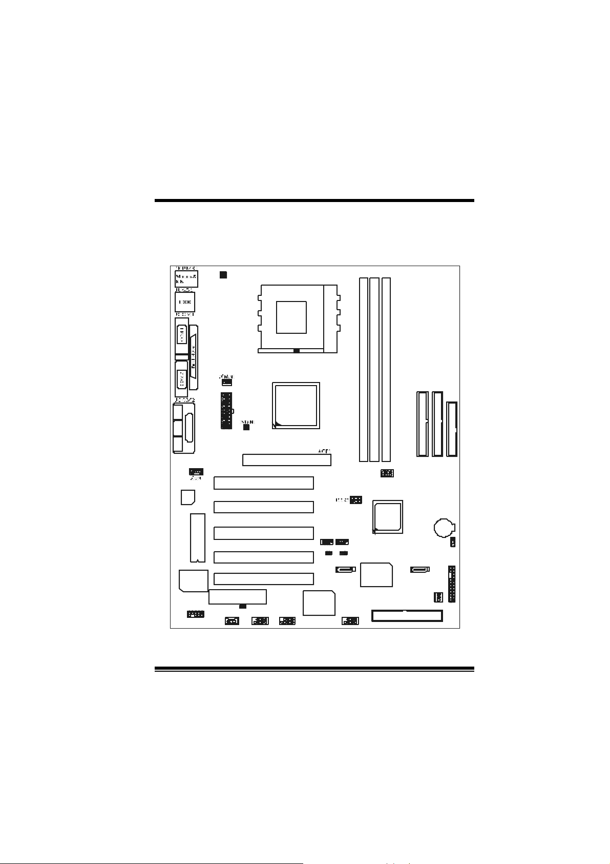
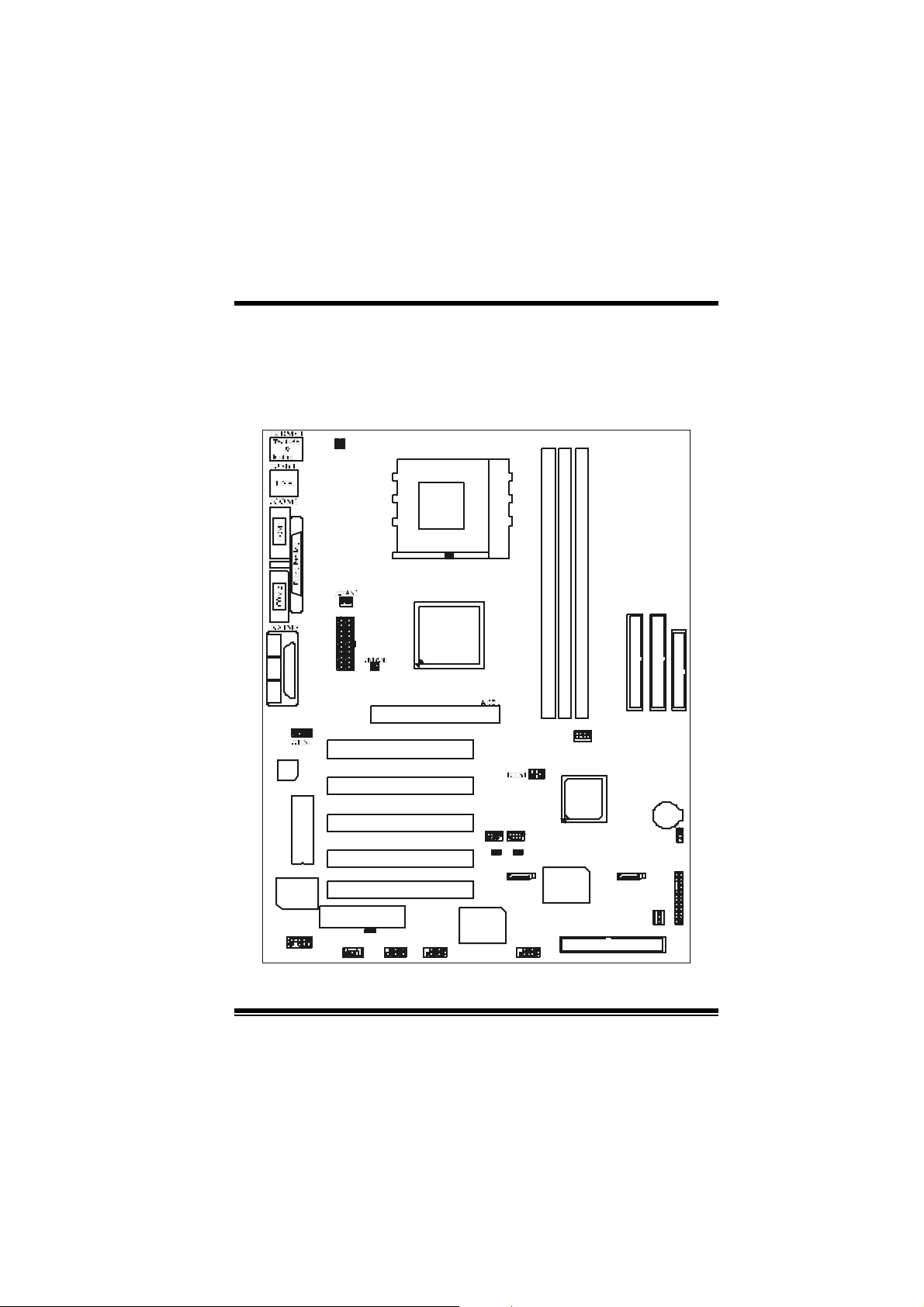
Layout of M7VI P (For Version 1.1 and
above)
1
1
JUSBV1
JKB V 1
CPU
S ock et A
DIMM1
DIMM2
1
JATXPWR1
SP- OUTMI C-I N LINE-IN
1
GA ME Po rt
VT 8367
KT 333
DIMM3
JGAME1
CMI9739
Winb ond
I / O
JAUDIO1
1
BIOS
CNR SLO T
JWO L1
1
1
1
PC I S LO T
PC I S LO T
PC I S LO T
PC I S LO T
PC I S LO T
JCODE CSEL1
J1394A1
10
AGP SLOT
CNR1
J1394B1
129
9
10
127
IDE1 IDE 2 FDD1
BAT1
JCMOS1
JPANEL1
JSATA2JS ATA1
JSFAN1
1
1
2324
12
JDIMMVOLT 1
1 23
JUSB3
JUSBV3
129
654
Co nt ro lle r
8
VT8235
Ser ia ls
ATA
RAID1
PCI1
PCI2
PCI3
JUSB2
10
10
129
JUSBV2
1394
CHIP
129
1
1
J1394C1
10
PCI4
PCI5
1
2
5
Page 8
M
M
M
r
e
h
t
o
e
h
t
o
r
e
h
t
o
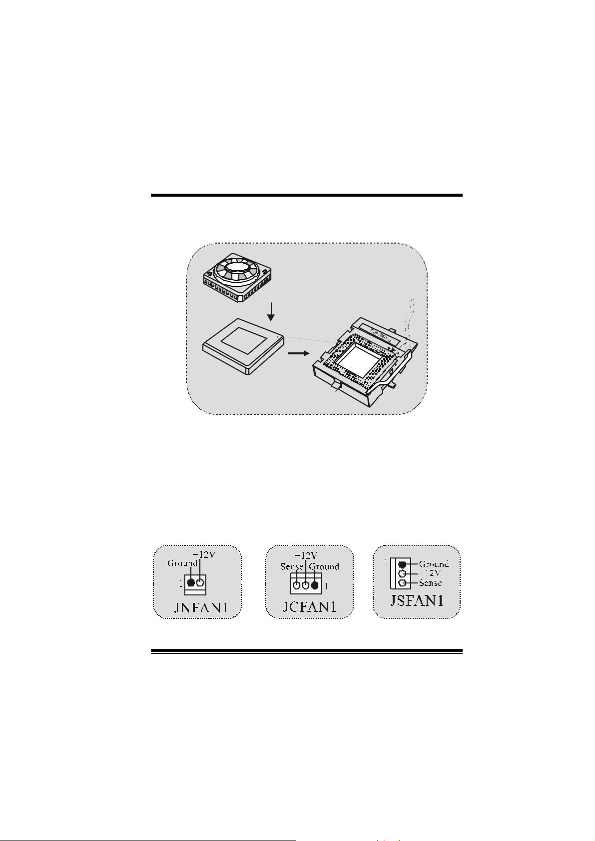
CPU Installation
b
b
b
r
d
r
a
o
d
r
a
o
r
c
s
e
D
r
c
s
e
D
n
o
i
t
p
i
n
o
i
t
p
i
n
o
i
t
p
i
r
c
s
e
D
d
r
a
o
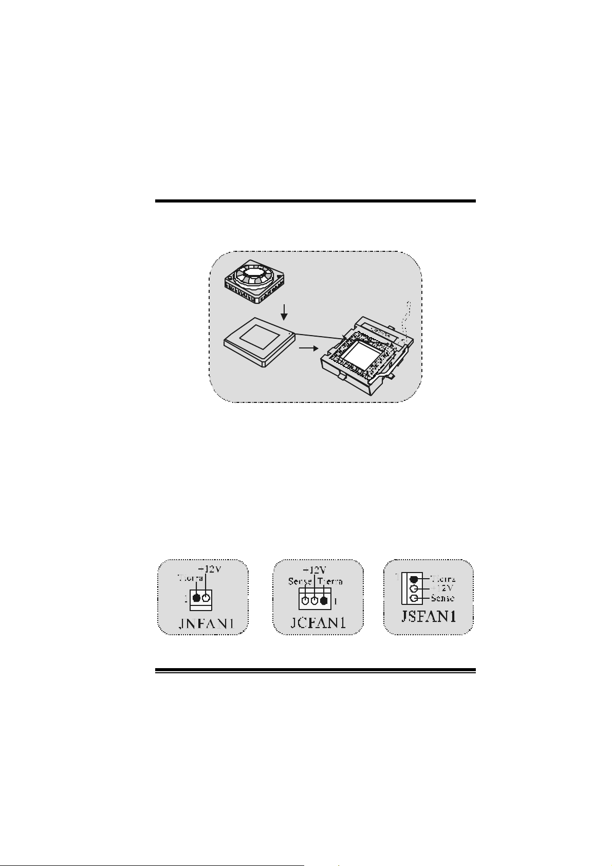
1. Pull the lever s ideways away f rom the s ock et then rais e the lever up
to 90-degree angle.
2. Locate Pin A in the soc ket and lock f or the white dot or cut edge in
the C PU. Matc h Pin A with the white dot/cut edge then insert t he
CPU.
3. Press the lever down. Then Put t he f an on the C PU and buckle it
and put the f an’s power port int o the JCF AN1, then to com plete t he
installation.
C
P
U
CPU/ System Fan Headers: JCFAN1/ JSFAN1/ JNFAN1
6
Page 9

M
M
M
Note: CPU Over Te mperat ure Protection
When the CPU temperature is over 110°C (for .13µ CPU) or 120°C
(for .18µ CPU), the system will automatically shut-down. If this
situat ion occurs, please ch eck if your CP U fan is working properly. If
no t , ch ang e the CPU fan , an d then res t art th e s y stem .
b
r
e
h
t
o
b
r
e
h
t
o
d
r
a
o
d
r
a
o
r
c
s
e
D
r
c
s
e
D
n
o
i
t
p
i
n
o
i
t
p
i
n
o
i
t
p
i
r
c
s
e
D
d
r
a
o
b
r
e
h
t
o
DDR DI MM Modules: DIMM1- 2- 3
DRAM Access Time: 2.5V Unbuffered/ Registered DDR 1600/ 2100/
2700 Type required.
DR AM Ty pe: 64MB/ 128MB/ 256MB/ 512MB/ 1GB DIMM Module (184
pin)
DIMM Sock et
Location
DI MM 1 64MB/128MB/256MB/ 512MB/1GB
DI MM 2 64MB/128MB/256MB/ 512MB/1GB
DIMM3 64MB/128MB/256MB/512MB/1GB
z The list s hown abov e for DRAM conf igurat ion is only f or ref erence.
*
If use FSB 333M Hz CPU, the Mem or y run only at DDR33 3
(PC2700). (For Version 1.1 and above)
DDR Modul e Total Memory
Size (MB)
*1
Max i s
*1
*1
7
3GB
Page 10
M
M
M
o
o
o
b
r
e
h
t
o
b
r
e
h
t
e
D
d
r
a
e
D
d
r
a
e
D
d
r
a
o
b
r
e
h
t
o
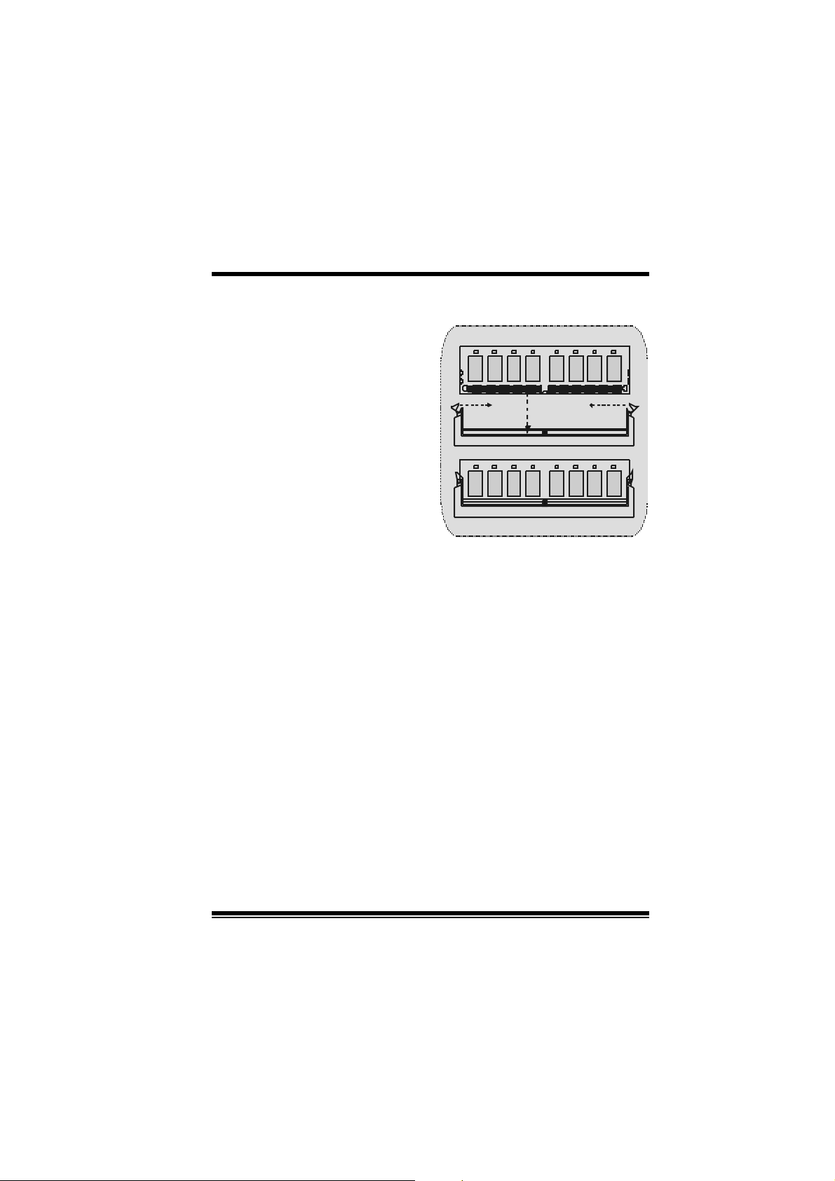
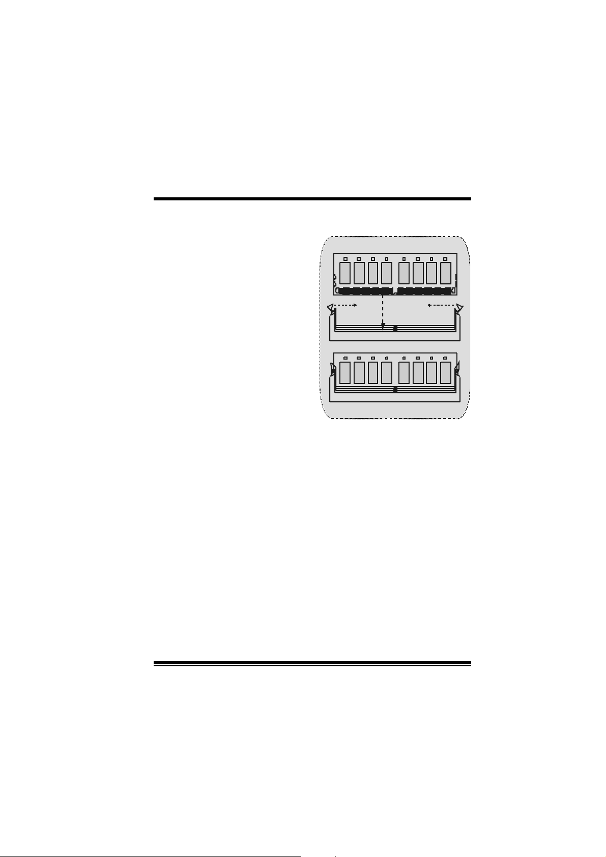
How to install a DIMM Module
1. The DIMM socket has a
“ Plastic Safety Tab”, and the
DIMM memory module has an
“Asymm etrical notch”, so the
DIMM memory module can only
fit in to the slot in one direction.
2. Pus h the tabs out . I nsert the
DIMM memory modules into the
soc k et at a 90-degree angle, t hen
push down v ertic ally s o t hat it will
fit into the place.
3. The Mounting Holes and plastic
tabs should f it over t he edge and
hold the DIMM memory m odules
in plac e.
s
r
c
s
r
c
s
n
o
i
t
p
i
n
o
i
t
p
i
n
o
i
t
p
i
r
c
8
Page 11

M
M
M
o
b
r
e
h
t
o
d
r
a
o
D
r
c
s
e
r
c
s
e
D
d
r
a
o
b
r
e
h
t
n
o
i
t
p
i
n
o
i
t
p
i
n
o
i
t
p
i
r
c
s
e
D
d
r
a
o
b
r
e
h
t
o
Jumpers, Headers, Connectors & Slots
Hard Disk Connectors: IDE1/ IDE2
The motherboard has a 32-bit Enhanced PCI IDE Controller that
provides PIO Mode 0~4, Bus Master, and Ultra D MA 33/ 66/ 100/ 133
functionality. It has two HDD connectors IDE1 (primary) and IDE2
(secondary ).
The ID E c onnect ors can connect a mast er and a s lav e drive, so you can
connect up to four hard dis k driv es. The first hard driv e should alway s be
connected to IDE1.
Floppy Disk Connector: FDD1
The motherboard prov ides a standard floppy disk connector that
supports 360K, 720K, 1.2M, 1.44M and 2.88M floppy disk types. This
connector supports the provided f loppy drive ribbon cables.
Communic ation Network Riser Slot: CNR1
The CNR specific ation is an open Industry St andard Arc hit ect ure, and it
def ines a hardware sc alable riser c ard int erf ac e, whic h supports audio,
and m odem only .
P er i p h er a l Co mpo nen t I n ter c onnec t S l o ts : PCI 1- 5
This m otherboard is equipped with 5 s tandard PCI s lots. PCI stands f or
Peripheral Component Interconnect, and it is a bus standard f or
expansion c ards, which has, supplanted t he older I SA bus st andard in
most ports . This PCI slot is designated as 32 bit s.
Accelerated Graphics Port Slot: AGP1
Your monitor will attach directly to that video card. This motherboard
supports video cards for PCI slots, but it is also equipped with an
Accelerated Graphics Port. An AGP card will take advantage of AGP
technology for improved video efficiency and perf ormance, especially
with 3D graphi cs.
Serial ATA Connector: (JSATA1/ JSATA2) (Optional)
The mot herboard has a PCI to SATA Controller with 2 channels SATA
interf ace, it satisfies the SATA 1.0 spec and can transfer data with
1.5GHz speed. For more details, please refer to page 21(FastTrak
376).
9
Page 12
M
(
)
(-)
)
(-)
)
M
M
o
b
r
e
h
t
o
d
r
a
o
D
r
c
s
e
r
c
s
e
D
d
r
a
o
b
r
e
h
t
n
o
i
t
p
i
n
o
i
t
p
i
n
o
i
t
p
i
r
c
s
e
D
d
r
a
o
b
r
e
h
t
o
Raid Connector: RAID1 (Optional)
This connector supports RAID0 or RAID1 configuration through the
onboard Serial ATA (FastTrak 376) c ont r ol le r ch ip. Y ou c a n u se t h e
IDE feature to set up a disk array con fig uration a nd to sup port addi tional
ID E devic es. H owev er, it c an only s upport master mode I D E HDD.
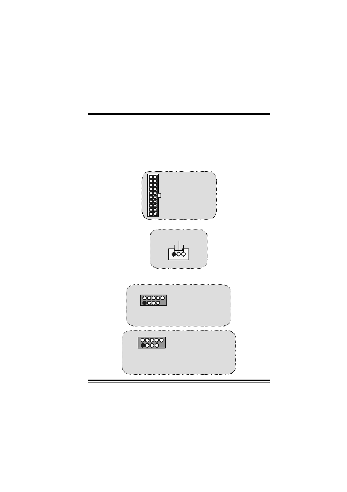
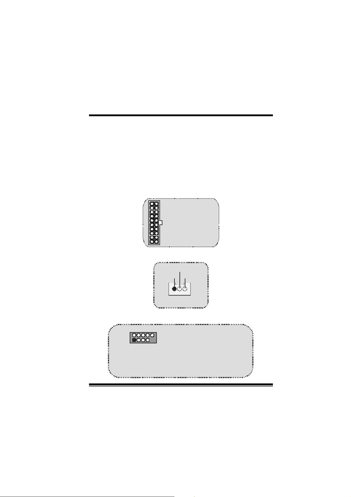
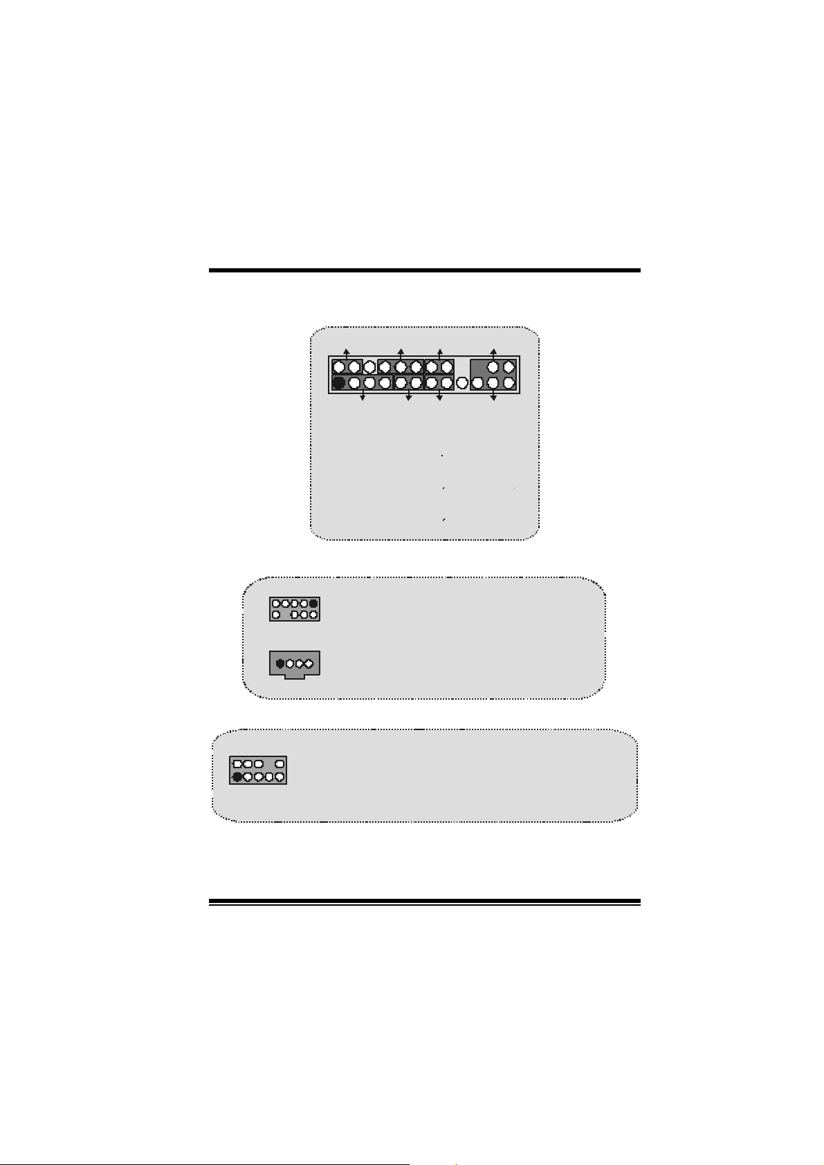
Power Connectors: JATXPWR1
JATXPWR1
(ATX Main Power Conn.)
JATXPWR1
ATX Power Conn.
Wake On LAN Header: JWOL1
Ground
5V_SB Wake up
1
WOL1
Front USB He ader: JUSB1/ JUSB2/ JUSB3
2
1
JUSB1/2
(For Version 1.0)
2
1
JUSB2/3
(For Version 1.1
and above)
Pin1,2 ==> +5V
Pin3,4 ==> Data
Pin5,6 ==> Data(+
Pin7,8 ==> Ground
Pin9 ==> KEY
P in 1 0 == > NA
Pin1,2 ==> +5V
Pin3,4 ==> Data
Pin5,6 ==> Data(+
Pin7,8 ==> Ground
Pin9 ==> KEY
Pin10 ==> NA
10
Page 13
M
_
M
M
o
b
r
e
h
t
o
d
r
a
o
D
r
c
s
e
r
c
s
e
D
d
r
a
o
b
r
e
h
t
n
o
i
t
p
i
n
o
i
t
p
i
n
o
i
t
p
i
r
c
s
e
D
d
r
a
o
b
r
e
h
t
o
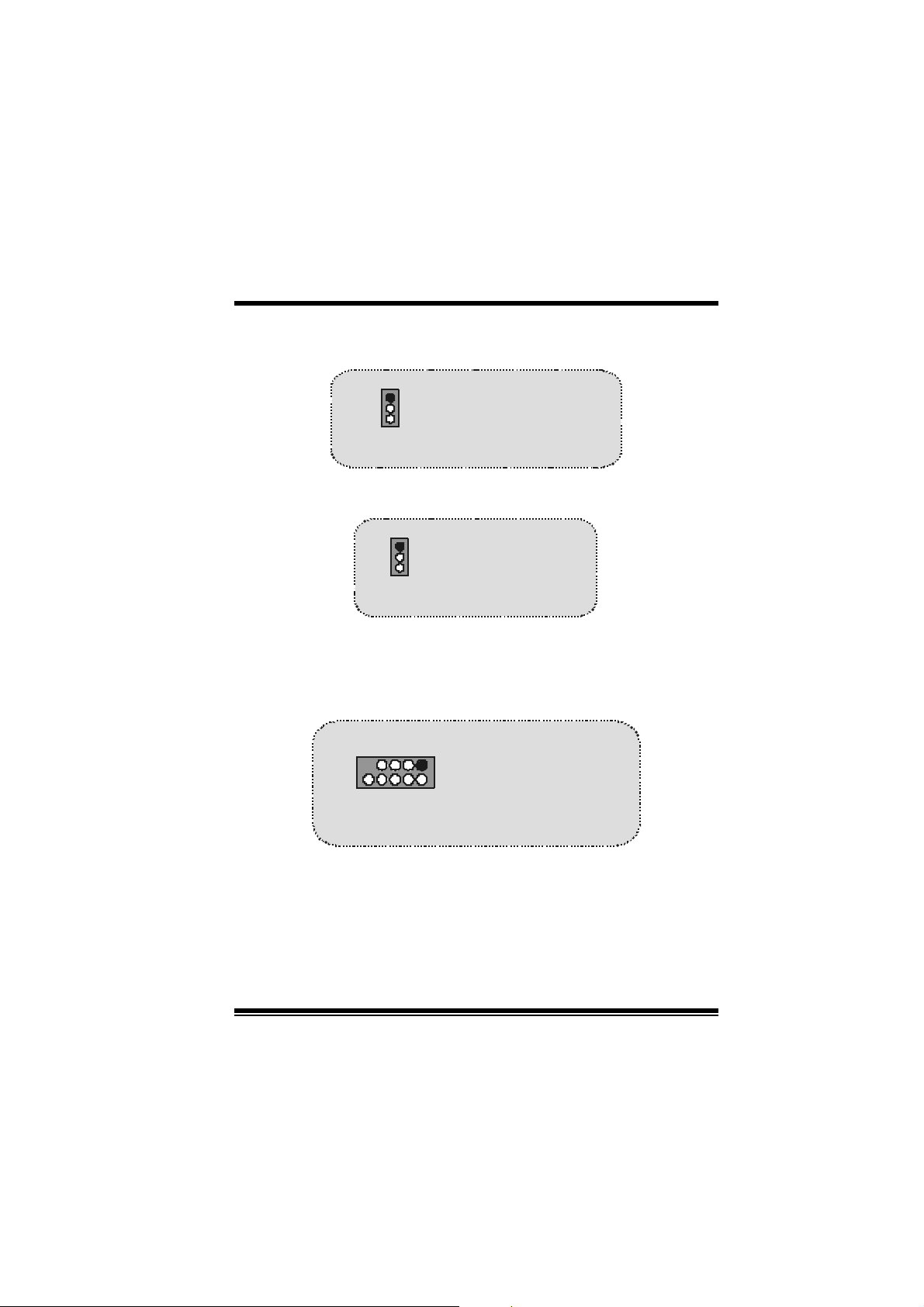
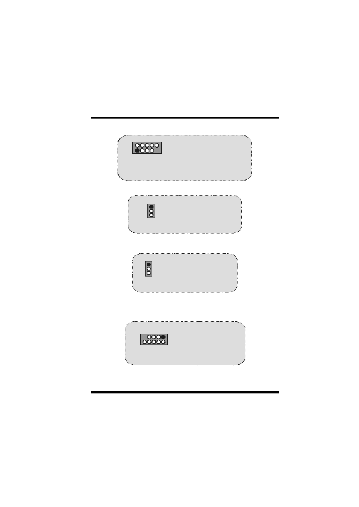
5V/ 5VSB Selection for USB: JUSBV1/2/3
1
JUSBV1/2/3
Pin 1-2 on ==> 5V
Pin 2-3 on ==> 5V_SB
5V/ 5VSB Selection for KB: JKBV1
1
JKBV1
Pin 1- 2 on ==> 5V
Pin 2- 3 on ==> 5V
SB
Front 1394 Header: J1394A1/ J1394B1/ J1394C1
(Opti onal)
2
1
J1394A1/B1/C1
JUSB3/4
Pin1,2 ==> +5V
Pin1,2 ==> A +/ APin3,4 ==> D ato (-)
Pin3,4 ==> G ro und
1
Pin5,6 ==> D ato (+)
Pin5,6 ==> B+/ B-
2
Pin7,8 ==> Tierr a
Pin7,8 ==> +12V
Pin9 ==> KEY
Pin9 ==> KEY
Pin10 ==> NA
Pin10 ==> NA
11
Page 14
M
(
)
M
M
o
b
r
e
h
t
o
d
r
a
o
D
r
c
s
e
r
c
s
e
D
d
r
a
o
b
r
e
h
t
n
o
i
t
p
i
n
o
i
t
p
i
n
o
i
t
p
i
r
c
s
e
D
d
r
a
o
b
r
e
h
t
o
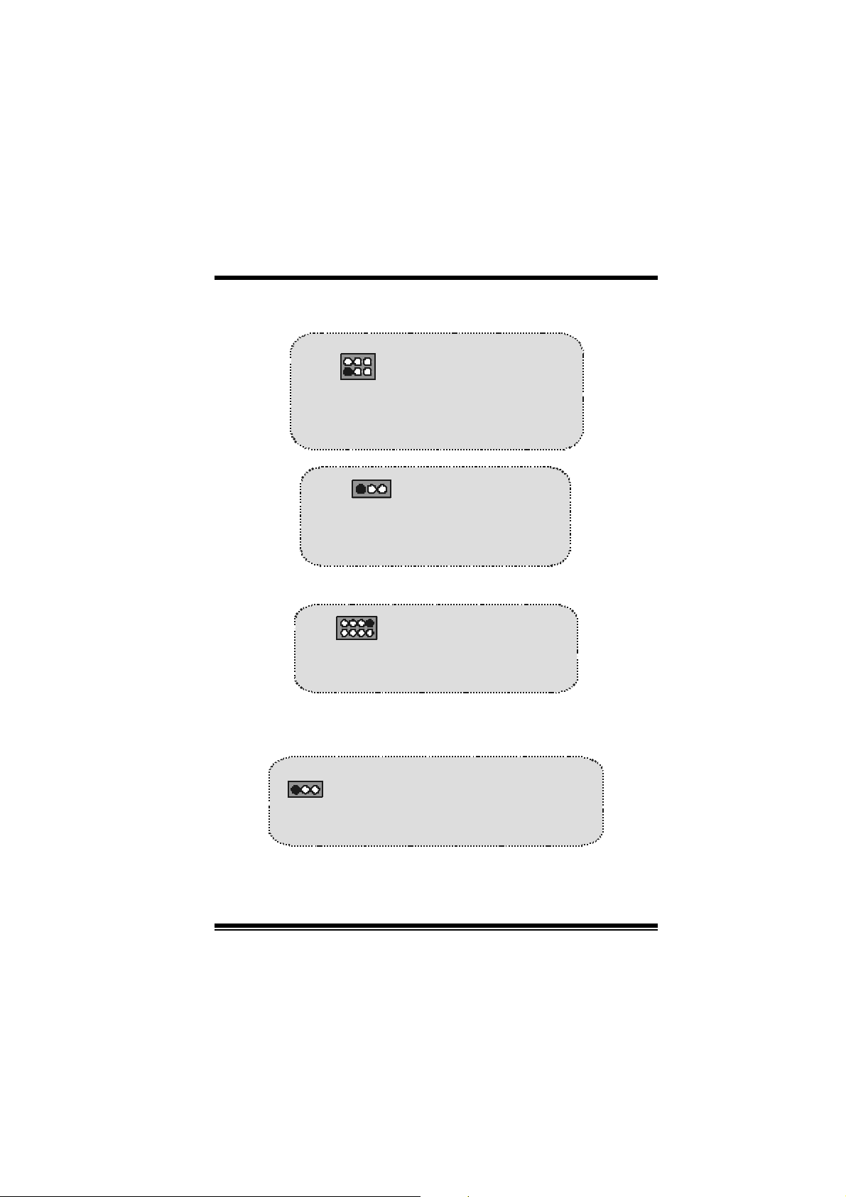
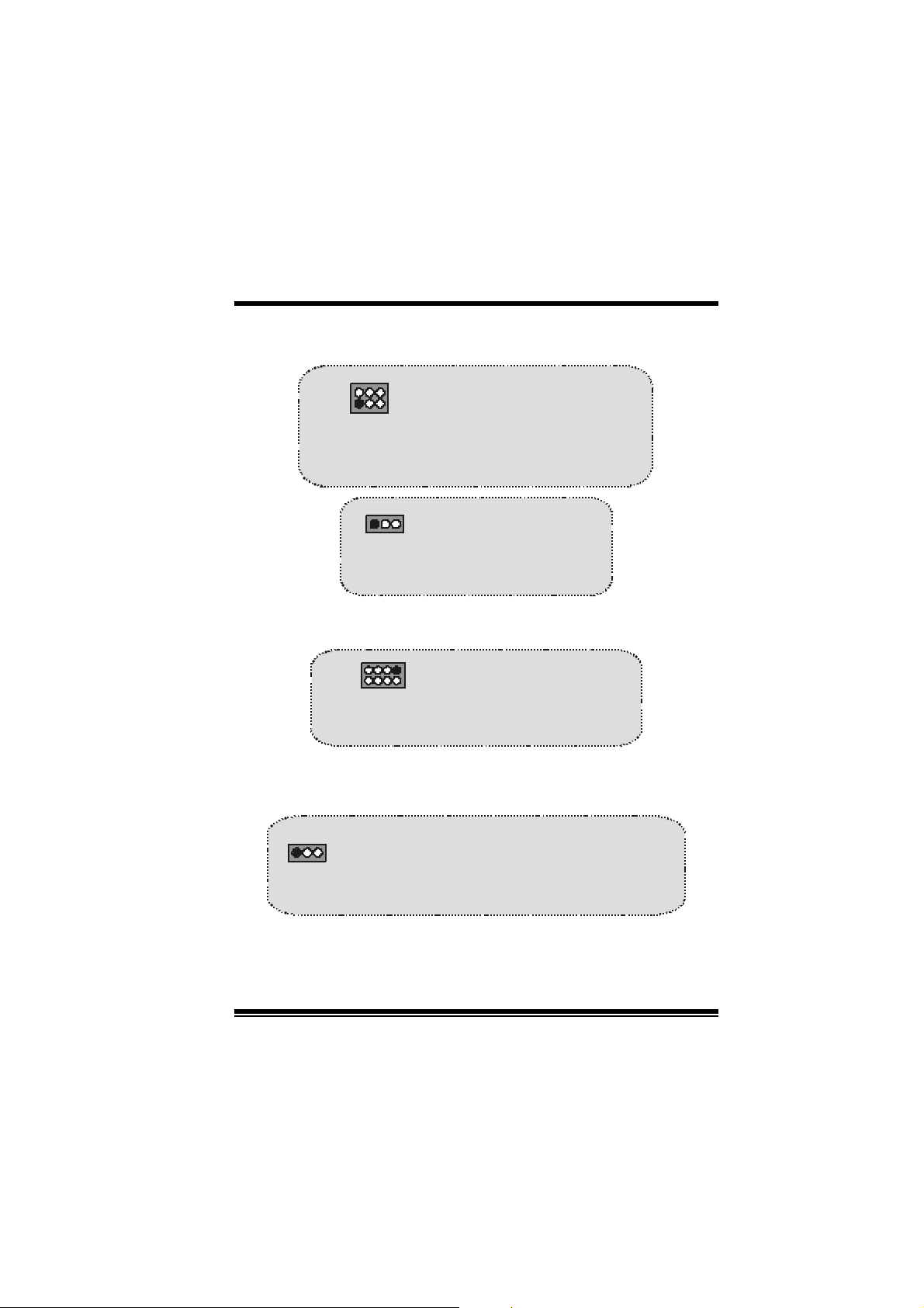
CP U Frequency Selection: JCLK1
1
JCLK1
(For Version 1.1 and above)
1
JCLK1
(For Version 1.0)
Pin 1-2, 5-6 ==> 10 0 Mhz
64
Pin 2-3, 5-6 ==> 13 3 Mhz
3
Pin 2-3, 4-5 ==> 16 6Mhz
Pi n 1-2 = => 100 Mhz
Pi n 2-3 = => 133 Mhz
(default)
default
DDR DIMM Voltage: JDIMMVOLT1
JDIMMVOLT1
(Defau lt ==> 2.5 V)
121
2
Pin 1-2 on ==> 2. 5V
Pin 3-4 on ==> 2. 6V
Pin 5-6 on ==> 2. 7V
Pin 7-8 on ==> 2. 8V
CNR Codec Primary/Secondary Selection:
JCO DEC S EL1
1
JCODECSEL1
Pin 1-2 = => On-board Primary Codec
Pin 2-3 = => CNR Primary Codec
12
Page 15
M
(
)
M
M
o
h
t
o
a
o
b
r
e
s
e
D
d
r
s
e
D
d
r
a
o
b
r
e
h
t
o
i
t
p
i
r
c
o
i
t
p
i
r
c
o
i
t
p
i
r
c
s
e
D
d
r
a
o
b
r
e
h
t
o
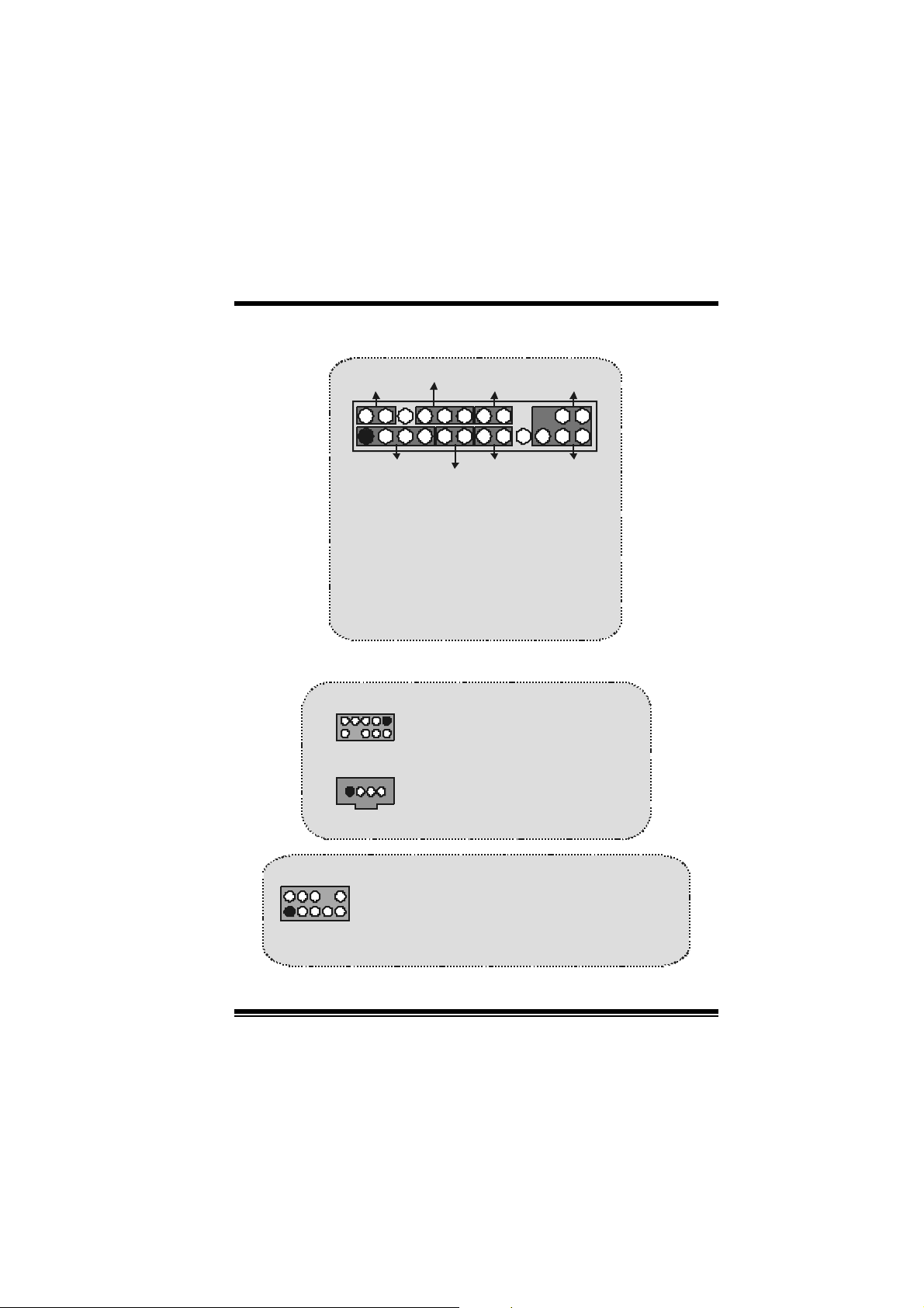
Front Panel Connector: JPANEL1
SLP
2
123
SPK ==> Speake r Conn.
HLED == > Hard Driver LED
RST ==> Reset Button
IR = => Inf ra red Conn.
SLP ==> Sleep Button
PWR_LED ==> Power LED
ON/ OFF ==> Power-on Button
SPK
PWR_LED
(+) (-)(+)
(+) (-)
HLED
RST
Audio S ubsystem: JAUDIO1/ J CDIN1
1
1
2
JAUDI O1
(Front Audio Header)
JCDIN1
CD-ROM Audio-In Header
n
n
n
IRON/O FF
24
IR
Pin1 ==> Mic In P in2 ==> Gr ound
2
1
JA UDI O1
Pin3 == > M ic Po w er Pin4 ==> A u d io P o w er
Pin5 ==> RT Line Out Pin6 ==> RT Line Out
Pin7 ==> Reserved Pin8 ==> KEY
Pin 9 ==> LFT Line Out Pin10 == > LFT Line Out
13
Page 16
a
p
o
b
r
e
h
t
o
12
910
12
910
M
h
t
o
M
h
t
o
M
Front Panel Audio Connector/ Jumper Block
Pin 5 and 6
==>
Pin 9 and 10
Audio line out and mic in signa ls are
available for front panel audio connectors.
a
o
b
r
e
a
o
b
r
e
Audio line out signals are routed
to the back
Clear CMOS Jumper: JCMOS1
1
JCMOS1
Pin 1-2 on ==> Normal Operation
(default)
Pin 2-3 on ==> Clea r CMOS Data
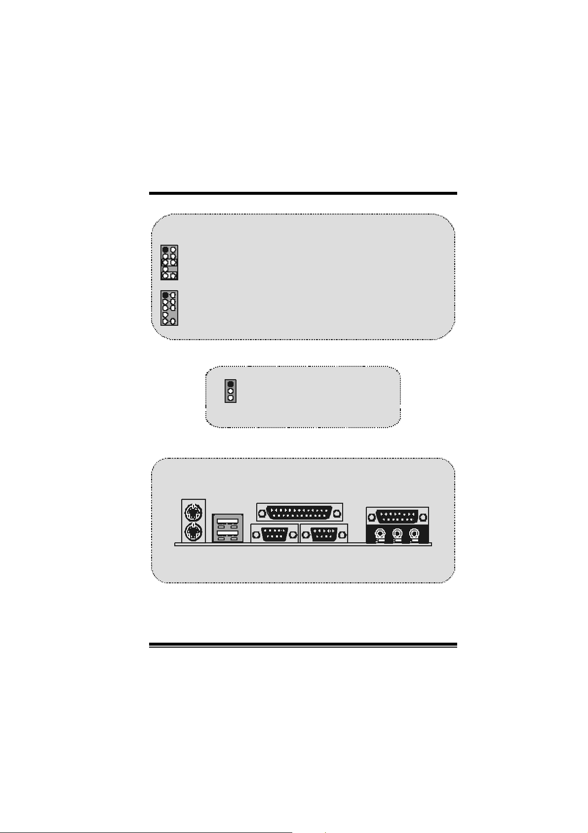
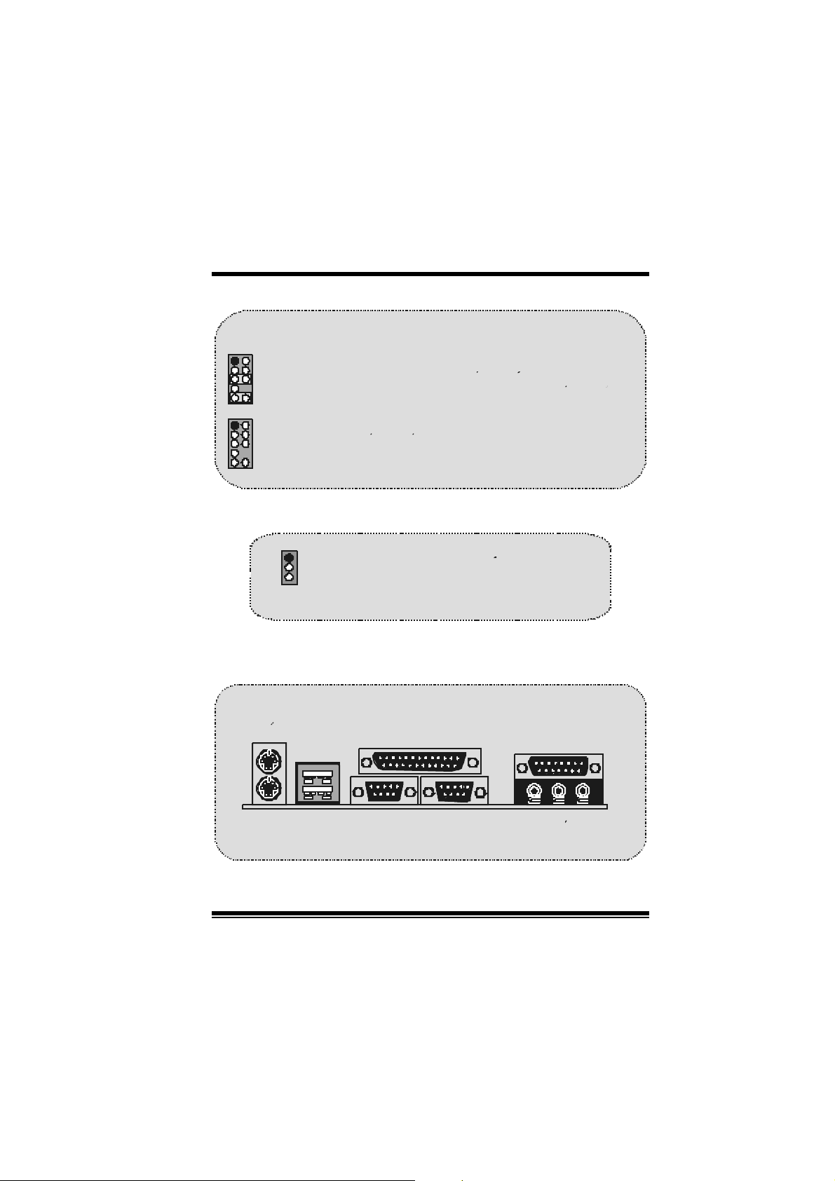
Ba ck Panel Connectors
r
d
r
d
r
r
c
s
e
D
r
c
s
e
D
anel audio lin e out con nector.
n
o
i
t
p
i
n
o
i
t
p
i
n
o
i
t
p
i
r
c
s
e
D
d
JK BMS1
PS /2
Mouse
JUSB1
PS/2
Keyboard
USB
JPRNT1
Parallel
COM1
COM1
COM1
COM1 COM2
JCOM1
JCOM2
14
Speake r
Out
JGAME1
Game Port
Li n e In Mic
In
Page 17

M
M
M
o
b
r
e
h
t
o
d
r
a
o
D
r
c
s
e
r
c
s
e
D
d
r
a
o
b
r
e
h
t
n
o
i
t
p
i
n
o
i
t
p
i
n
o
i
t
p
i
r
c
s
e
D
d
r
a
o
b
r
e
h
t
o
Español
Características del M7VIP
Us a Chips ets VIA VT8367 (KT333)/ VT8235 y Winbond W83697HF.
Contiene facilidades I/ O integrados en la placa madre en el que incluye
dos puertos en serie, un puerto paralelo, un puerto para el rat ón PS/ 2, un
puerto para teclado PS/2, puertos de audio, puertos USB y puerto de
juego.
Soporta Single Socket-A para procesadores de la f am ilia AMD Athlon/
Duron, corriendo a 200 o 266 MHz frecuencia Front Side Bus. (Para
Versión 1.0)
Soporta Single Socket-A para procesadores de la f am ilia AMD Athlon/
Duron, c orriendo a 200, 266 o 333MHz frecuenc ia F ront Side Bus. (Para
Versiones 1. 1 en adelant e)
El sistema bus AMD Athlon soporta alta velocidad de 200/266 MHz,
sistema bus split -trans action AMD At hlon de int erface. (Para Version 1.0)
El sistema bus AMD Athlon soporta alta v elocidad de 200/266/333 MHz,
sistema bus s plit -t ransaction AMD Athlon de interf ac e. (Para Versiones 1. 1
en adelant e)
Soporta Modos Ultra DMA 33/66/100/ 133 Bus Master, Modo 4 PIO, Modo
Master, y alta perform ancia del disco duro.
Soporta Dis positivo USB2.0 High Speed, 2 puertos en el panel trasero y 4
puertos en el panel f rontal.
El sistema controlador VT8367 (KT333) está diseñado para s oportar DDR
SDR AM D I MMs de 200/266/333 MH z.
Soporta una memoria máxim a de has t a 3GB.
Soporta una ranura CNR (solamente de Tipo B), una ranura AGP (AGP
4X), y cinc o ranuras de 32-bit PCI Bus .
Com patible con las especif icac iones del f actor de forma de tam año de PC
ATX.
Soporta sistemas operativ os populares tales c omo Windows NT, W indows
15
Page 18

M
M
M
98SE, Windows 2000, Windows ME, Windows XP y LINUX.
Protección contra exceso de tem peratura del CPU.
Com patible con Intel® AC’97 2.2. H igh S/N ratio reune los requis itos del
PC 99.
Entrada del Línea phonejack y Entrada del Micrófono jack compartido c on
el rear Audio out para canales de 6 Audios.
Soporta funciones del cabezal del audio frontal.
Soporta función de reinicio desde el U SB del teclado/ ratón.
Soporta 3 puertos de la función f irewire 1394 (Opc ional).
Soporta 2 en serie y 1 paralelo f unc ión Serial ATA y Raid (Opcional).
Soporta fun ción over spe ed/ vol ta ge (Opcio nal ).
b
r
e
h
t
o
b
r
e
h
t
o
d
r
a
o
d
r
a
o
r
c
s
e
D
r
c
s
e
D
n
o
i
t
p
i
n
o
i
t
p
i
n
o
i
t
p
i
r
c
s
e
D
d
r
a
o
b
r
e
h
t
o
Conte ni do de l Pa quete
Cable HD D X 1, Cable FDD X 1, Configurac ión completa del D riv er CD X 1
Flas h Mem ory Writer para act ualización del BIOS X 1
Cable USB X 2 (Opcional)
Panel t ras ero I/O para caja ATX X 1 (Opcional)
16
Page 19
M
M
M
o
b
r
e
h
t
o
d
r
a
o
D
r
c
s
e
r
c
s
e
D
d
r
a
o
b
r
e
h
t
n
o
i
t
p
i
n
o
i
t
p
i
n
o
i
t
p
i
r
c
s
e
D
d
r
a
o
b
r
e
h
t
o
Dis posición del M7VIP (Para Versión 1.0)
1
1
JUSB V1
JKBV1
CPU
Sock et A
DIMM3
DIMM 1
1
JUSB 2
J DIMMVOLT 1
VT8235
Controlador
Serial
ATA
1
2
DIMM2
8
RAID1
IDE1 IDE2 FDD1
127
JCM OS1
JSATA2JSATA1
JSFAN1
S ali da del
Altav oz
Ent r ada
de Linea
Ent r ada
del MIC
JGAME1
CMI9739
Winbond
I / O
JAUDIO1
1
JATXPWR1
VT8367
(KT333)
1
Pue rto de Juego
Ra nura AGP
1
Ranura PCI
Ranura PCI
Ranura PCI
BIOS
Ranura PCI
Ranura PCI
Ranura CNR
JCODECSEL1
1
JWOL 1
1
CNR1
1
J1394A1 J1394B1
1
9
2
10
PCI1
PCI2
PCI3
JUSB1
10
10
129
JUSBV2
1394
CHIP
J1394C1
129
1
1
JUSBV3
9
10
PCI4
PCI5
1
9
2
10
BAT1
JPANEL1
1
1
2324
12
17
Page 20
M
(
)
M
M
o
b
r
e
h
t
o
d
r
a
o
D
r
c
s
e
r
c
s
e
D
d
r
a
o
b
r
e
h
t
n
o
i
t
p
i
n
o
i
t
p
i
n
o
i
t
p
i
r
c
s
e
D
d
r
a
o
b
r
e
h
t
o
Disposición del M7VIP (Para Versio nes 1.1
en adelante)
1
1
JUSBV1
JKBV1
CPU
Socket A
DIMM1
DIMM2
JDIMMVOLT1
654
Controlador
Ser ial
ATA
129
DIMM3
8
VT8235
RAID1
127
IDE1 IDE2 FDD1
BAT1
JCMOS1
JPAN EL1
JSATA2JSATA1
JSFAN1
1
1
2324
12
Salida del
Altavoz
Entrada
de L i n e a
Entra d a
del MIC
JGAME1
CMI9739
Winbond
I / O
JAUDIO1
1
JATXPWR1
V T8367
KT 333
1
Pu erto de Juego
1
BIOS
Ran ura C NR
JCODECSEL 1
1
JWO L1
1
Ranura AGP
Ranura PCI
Ranura PCI
Ranura PCI
Ranura PCI
Ranura PCI
CNR1
1
J1394A1 J1394B1
129
10
10
PCI1
PCI2
PCI3
JUSB2
PCI4
JUSBV 2
PCI5
1394
CHIP
129
J1394C1
129
1
1 23
10
10
JUSB3
129
1
JUSBV3
10
18
Page 21
M
M
M
o
b
r
e
h
t
o
d
r
a
o
D
r
c
s
e
r
c
s
e
D
d
r
a
o
b
r
e
h
t
n
o
i
t
p
i
n
o
i
t
p
i
n
o
i
t
p
i
r
c
s
e
D
d
r
a
o
b
r
e
h
t
o
Instalación de la CPU
C
P
1. Tire de la palanca del lado del zócalo, luego lev ante la palanca
hast a un ángulo de 90 grados .
2. Sitúe el cont act o A del zóc alo y busque el punto blanco o corte el
borde en la CPU. Empareje el contacto A con el punto blanco/
cort e del borde, luego ins erte la CPU.
3. Presione la palanca para abajo. Ponga el ventilador en la CPU y
abróchelo. Luego ponga el puert o de corriente del ventilador en el
JCFAN1. Y y a h abrá compl etado su in stalación.
CP U/ Cabezal del Sistema de Ventilación: JCFAN1/
JSFAN 1/ JNFAN1
U
19
Page 22

M
M
M
Nota: Protección contra el exceso de temperatura
Cuando l a temperat ura d e la CP U esté sobre los 100°C (para CP U . 13µ)
o 1 10°C (p ara CP U .18µ ), el sistem a se apag ará aut omáticam ent e. Si
esta situación ocurre, por favor asegúres e que el ventilador de la CPU
esté funcionando correctamente. Si no, cambie el ventilador de la
C P U y vuel va a in i ci ar el si s t ema.
b
r
e
h
t
o
b
r
e
h
t
o
d
r
a
o
d
r
a
o
r
c
s
e
D
r
c
s
e
D
n
o
i
t
p
i
n
o
i
t
p
i
n
o
i
t
p
i
r
c
s
e
D
d
r
a
o
b
r
e
h
t
o
Módulos DDR DIMM: DIMM1-2-3
DRAM Tiempo de Acceso: 2.5V Unbuffered/ Registered DDR 1600/
2100/ 2700 Tipo requerido.
DR AM Tipo: 64MB/ 128MB/ 256MB/ 512MB/ 1GB Módulo DIMM (184
contactos)
Locali zación
del Zócal o
DIMM
DI MM 1 64MB/128MB/256MB/ 512MB/1GB
DI MM 2 64MB/128MB/256MB/ 512MB/1GB
DIMM3 64MB/128MB/256MB/512MB/1GB
z La lista de arriba para la conf iguración DRAM es solamente para
referencia.
*
Si util iza FS B 3 33M Hz CP U, la memori a c orre solamente
a DDR333 (PC2700). (Para versiones 1.1 en adelante)
Módulo DDR Total del
Tamaño de la
Memoria (MB)
*1
Máximo de
*1
*1
20
3GB
Page 23
M
M
M
o
e
h
t
o
d
r
a
o
b
r
d
r
a
o
b
r
e
h
t
c
s
e
D
c
s
e
D
c
s
e
D
d
r
a
o
b
r
e
h
t
o
Cómo instalar un M ódulo DIM M
1. El zócalo DIMM tiene una
lengüeta plástica de seguridad y
el módulo de memoria DIMM
tiene una m uesc a as imétrica, así
el módulo de memoria DIMM
puede caber solamente en la
ranura de una sóla direcc ión.
2. Tire la lengüeta hacia afuera.
Inserte los módulos de memoria
DIMM en el zócalo a los 90
grados , luego empuje hacia abajo
verticalmente de modo que
encaje en el lugar.
3. Los agujeros de m ontaje y las
lengüetas plásticas deben caber
por sobre el borde y sostenga los
módulos de mem oria DIMM en el
lugar.
r
r
r
n
o
i
t
p
i
n
o
i
t
p
i
n
o
i
t
p
i
21
Page 24

M
M
M
o
b
r
e
h
t
o
d
r
a
o
D
r
c
s
e
r
c
s
e
D
d
r
a
o
b
r
e
h
t
n
o
i
t
p
i
n
o
i
t
p
i
n
o
i
t
p
i
r
c
s
e
D
d
r
a
o
b
r
e
h
t
o
Puentes, Cabezales, Conectore s y Ranuras
Conectores del Disco Duro: IDE1/ IDE2
La plac a m adre tiene un controlador de 32-bit PCI I DE que proporciona
Modo PI O 0~4, Bus Master, y f unc ionalidad Ultra D MA / 33/ 66/ 100.
Tiene dos c onect ores HDD ID E1 (primario) y IDE2 (sec undario).
El conector IDE puede conectar a un master y un drive esclavo, así
puede c onectar hasta cuatro discos rí gidos . El primer disc o duro debe
est ar siem pre conectado al I D E1.
Conector para Disque te: FDD1
La plac a madre proporciona un conector estándar del disquete (FDC )
que s oporta 360K, 720K, 1.2M, 1. 44M y 2.88M tipos de dis quete. Éste
conector utiliza los cables de cint a proporcionados por el dis quet e.
Ra nura de la Banda de Su spensión de Comuni cación y
La es pec ificac ión CNR es una abierta I ndust ria de Arquitec t ura Estándar,
que define una tarjeta de interface escalable del hardware en el que
soporta audio y m odem .
Ranura de Intercon exión del Componente Periférico :
Ést a placa madre está equipada c on 5 ranuras estándar PCI. PCI es la
sigla para Interconexión del Componente Periférico, y es un bus
est ándar para t arjet as de expansión en el que suplant a a la antigua bus
estándar ISA, en su mayoría de las partes. Ésta ranura PCI está
diseñado con 32 bits.
Ranura del Puerto Acelerado para Gráficos: AGP1
Su monitor se f ijará direc t am ente a la tarjeta de video. Ésta placa madre
soporta t arjetas de v ideo para ranuras PCI, y t ambién está equipado con
un Puert o Acelerado para Gráficos. Ésta tarjeta AGP tomará v entaja de
la tecnología del AGP para el mejoramiento de la eficiencia y
funcionamient o del video, espec ialm ente con gráficos 3D.
Conector Serial ATA: (JSATA1/ JSATA2) (Opcional)
Ést a placa madre contiene un PCI junt o a un controlador SATA con 2
canales de interface SATA, que satisface el spec de SATA 1.0 y
también puede transferir datos de hasta una velocidad de 1.5GHz.
Red: CNR1
PCI1-5
22
Page 25
M
p
(-)
)
M
M
Para m ás inf ormación, por favor ref iérase a la página 21 (Fas t Trak 376).
b
r
e
h
t
o
b
r
e
h
t
o
d
r
a
o
d
r
a
o
r
c
s
e
D
r
c
s
e
D
n
o
i
t
p
i
n
o
i
t
p
i
n
o
i
t
p
i
r
c
s
e
D
d
r
a
o
b
r
e
h
t
o
Raid Connector: RAID1 (Opcional)
Ést e c onect or soporta c onf iguración R AI D0 o RAID1 por medio del chip
controlador Serial ATA (FastTrak 376) integrado en la placa madre.
Usted puede usar las características del IDE para conf igurar la
configuración de un disk array y para soport ar dis positivos adicionales
del I D E. Sin embargo, s olament e puede soportar m odo master del IDE
HDD.
Conector de Corriente : JATXPWR1
JATXPWR 1
(Conector de
Corriente ATX)
Cabezal Wake On LAN: JWOL1
Tierra
5V_SB Wake u
1
WO L1
Cabezal Frontal USB: JUSB1/ JUSB 2/ JUSB3
2
1
JUSB2/3
(Pa ra Versiones 1.1
en adelante)
Cont act o1,2 ==> +5V
Contact o3, 4 ==> D a to
Contact o5, 6 ==> D a to(+
Contact o7, 8 ==> Tier r a
Contact o9 ==> KEY
Con tac to10 ==> NA
23
Page 26
M
_
_
(-)
)
(-)
)
M
M
2
1
JUSB1/2
(P ara Version 1.0)
o
b
r
e
h
t
o
d
r
a
o
Contacto1,2 ==> +5V
Contac to3,4 ==> Dato
Contac to5,6 ==> Dato(+
Contac to7,8 ==> Tierra
Contacto9 ==> K EY
Contacto10 ==> NA
D
r
c
s
e
r
c
s
e
D
d
r
a
o
b
r
e
h
t
n
o
i
t
p
i
n
o
i
t
p
i
n
o
i
t
p
i
r
c
s
e
D
d
r
a
o
b
r
e
h
t
o
5V/ 5VSB Selección para USB: JUSBV1/2/3
1
JUSBV1/2/3
Contacto 1-2 on ==> 5V
Contacto 2-3 on ==> 5V
SB
5V/ 5VSB Sele cción para KB: JKBV1
1
JKBV1
Contacto 1- 2 on ==> 5V
Contacto 2- 3 on ==> 5V
SB
Cabezal Frontal 1394: J1394A1/ J1394B1/ J1394C 1
(Opcional)
2
1
J1394A1/B1/C1
JUSB3/4
Contacto1,2 ==> A+/A-
Pin1,2 ==> +5V
Contacto3,4 ==> Tier ra
Pin3,4 ==> Dato
1
Pin5,6 ==> Dato(+
Contacto5,6 ==> B+/ B-
2
Pin7,8 ==> T ierra
Contacto7,8 ==> +12V
Pin9 ==> KEY
Contacto9 ==> KEY
Pin10 ==> NA
Contacto10 == > NA
24
Page 27
M
(
)
(
M
M
o
b
r
e
h
t
o
d
r
a
o
D
r
c
s
e
r
c
s
e
D
d
r
a
o
b
r
e
h
t
n
o
i
t
p
i
n
o
i
t
p
i
n
o
i
t
p
i
r
c
s
e
D
d
r
a
o
b
r
e
h
t
o
S elección de la Frecuencia del CPU: JCLK1
1
JCLK1
(Para Versiones 1.1
en ad elante)
1
JCLK1
(Para Version 1.0)
64
3
Contacto 1- 2, 5-6 ==> 100 Mhz
Contacto 2- 3, 5-6 ==> 133 Mhz
Contacto 2- 3, 4-5 ==> 166Mhz
Contacto 1-2 ==> 100 Mhz
Contacto 2-3 ==> 133 Mhz
default
default)
Voltaje DDR DIMM: JDIMMVOLT1
JDIMMVOLT1
(Default ==> 2.5V)
121
2
Contacto 1-2 on == > 2.5V
Contacto 3-4 on == > 2.6V
Contacto 5-6 on == > 2.7V
Contacto 7-8 on == > 2.8V
S elección Code c Prima rio/ Secundario C NR:
JCO DEC S EL1
1
Contacto 1-2 ==> Codec Primario On-boa rd
Contacto 2-3 ==> Codec Primario C NR
JCODECSEL1
25
Page 28
M
(
)
M
M
o
b
r
e
h
t
o
d
r
a
o
D
r
c
s
e
r
c
s
e
D
d
r
a
o
b
r
e
h
t
n
o
i
t
p
i
n
o
i
t
p
i
n
o
i
t
p
i
r
c
s
e
D
d
r
a
o
b
r
e
h
t
o
Conector del Panel Frontal : JPANEL1
2
123
PWR_LE D
SL P
SPK
HLED
RST
SPK ==> Conector d e Altavoz
HLED ==> LED del Disco D uro
RS T ==> Boton de Reinicio
IR ==> Conector Infrarojo
SLP ==> Boton de Suspension
PWR_LED ==> Corriente LED
ON / OFF ==> Boton de Encendido
IRON/OFF
24
IR
Subsistema de Audio: JAUDIO1/ JCDIN1
1
2
(Cabezal de Audio Frontal)
1
Pin1 ==> Entrada del Mic Pin2 ==> Tierra
2
1
JAUDI O1
Pin3 ==> Corriente del Mic Pin4 ==> Corriente del Audio
Pin5 ==> RT Salida de Linea Pin6 ==> RT Salida de Linea
Pin7 ==> Reservado Pin8 ==> K EY
Pi n9 = => L FT Salida de L i nea Pin10 ==> L FT Salida de Linea
Cabezal de Entrada de Audio CD-ROM
JAUDIO1
JCDI N1
26
Page 29
D
)
d
r
a
o
b
r
e
h
t
o
12
910
12
910
M
M
M
Conector del Panel Frontal de Audio/ Jumper Block
Pin 5 y 6
==>
Pin 9 y 10
~ ~
La senal de salida de linea del Audio y la senal de Entrada
del Mic estan disponibl es desde el conector de Audio
del panel frontal.
b
r
e
h
t
o
b
r
e
h
t
o
La senal de s alida de linea del Audio
encamina al conector de la salida de linea
del Audio ubicado en el panel trasero.
D
d
r
a
o
D
d
r
a
o
~
Pu ente de Borrar C MOS: J CMOS 1
e
r
c
s
e
r
c
s
e
n
o
i
t
p
i
n
o
i
t
p
i
n
o
i
t
p
i
r
c
s
1
Conta c to 1-2 on ==> Operacion Normal (default
Conta c to 2-3 on ==> Borr a r Datos CMOS
JCMOS1
Conectores del Panel Tras ero
JK BMS1
Raton
PS/2
JUSB1
Teclado
PS/2
USB
COM1
JCOM1
JPRNT1
Par alelo
27
COM2
JCOM2
Salida del
Altavoz
JGAME1
Pue r t o d e Ju ego
En tra d a
de Linea
En trada
del MIC
Page 30

M
M
M
o
b
r
e
h
t
o
d
r
a
o
D
r
c
s
e
r
c
s
e
D
d
r
a
o
b
r
e
h
t
n
o
i
t
p
i
n
o
i
t
p
i
n
o
i
t
p
i
r
c
s
e
D
d
r
a
o
b
r
e
h
t
o
Serial ATA C hip - FastTrak 376
Ste p 1: Installing the Hard Drives
Importan t
If you wish to include your c urrent bootable Serial or Parallel
ATA drive using the Windows NT 4. x, Windows 2000, or
Windows XP operating syst em on y our F astTrak 376 C ontroller.
Y ou MU ST ins t all the Windows NT4, 2000, or XP driv er soft ware
first ont o this drive while it is still attached to your existing hard
drive controller.
1. Conf i gu r e t h e jum pers of the Parallel AT A hard drive y ou ’re preparing
to connec t t o the F astTrak 376 controller using the proper Master,
Slav e, or Cable-Select settings. For more information, refer to the
manual that cam e wit h your hard driv e.
2. Install all of t he hard driv es into the hard drive bays of y our sys t em,
including their power cables.
3. Attach the Parallel ATA c able to t he hard driv e(s ) and to the Parallel
ATA Port connec t or on t he FastTrak 376 controller. The c olored edge
of the c able indic ates pin 1. The blue cable connector attaches to t he
FastTrak 376.
4. Attach Serial ATA data c able to each hard drive. Then attach the ot her
ends of the cables t o one of the Serial ATA ports on t he FastTrak 376
controller. All of the c onnectors are k eyed so they will only at t ac h one
way.
No t e
FastTrak 376 is a PCI Plug-n-Play (PnP) devic e. No c hanges are
necessary in the Motherboard C MOS Setup for resources or
drive types in most applications.
28
Page 31

M
M
M
o
b
r
e
h
t
o
d
r
a
o
D
r
c
s
e
r
c
s
e
D
d
r
a
o
b
r
e
h
t
n
o
i
t
p
i
n
o
i
t
p
i
n
o
i
t
p
i
r
c
s
e
D
d
r
a
o
b
r
e
h
t
o
St ep 2: Aut o S etup Fast Build™
Configuration Utility
WARNING: Before installing the driver into an existing
system, backup any necessary data. Failure to follow this
accept ed PC pract ice could result in data loss.
Cre ati ng Your Disk Array
Yo u will now use the FastBuild™ Configuration u tility to create your arra y using
the att ac hed driv es. There are three dif f erent scenarios in creat ing t his array.
You can create an array for performance, y ou can create a Security array using
new hard driv es (recomm ended), or y ou can create a Security array us ing an
existing hard driv e and a new hard driv e.
WARNING: If creating a Security array using an existing
ha rd dr ive, ba ckup any necessa ry data. Failure t o f oll ow thi s
accept ed PC pract ice could result in data loss.
1. Boot your system. If t his is the f irst tim e you have booted wit h the
Fas t Trak 376 and driv es inst alled, t he Prom is e onboard B IOS will display
the f o ll ow ing s creen .
FastTrak 376 (t m ) BIOS Version 1.00.0. XX
(c ) 2002-2005 Promise Technology, Inc. All Rights Reserv ed.
No array def ined . . .
Press <Ctrl-F> to enter FastBuild (tm) Utility
Or pres s <ESC > key t o cont inue boot ing the sy st em.
29
Page 32

M
M
M
2. Pres s <C trl-F> k eys to display t he FastBuild™ Ut ility Main Menu.
FastBuild (tm) Utility 2.xx (c) 2002-2005 Prom ise Tec hnology, I nc.
Auto Setup....................................... [ 1 ]
View Drive Assignments......................[ 2 ]
View Array........................................[ 3 ]
Delete Array .....................................[ 4 ]
Rebuild Array.................................... [ 5 ]
Press 1...5 to Select Option [ESC] Exit
3. Press “1” t o dis play the Aut o Setup Menu below. This is the f ast est and
easiest me tho d to creating your first array.
FastBuild (tm) Utility 2.xx (c) 2002-2005 Prom is e Technology, I nc.
Optimize Array for: Performance
Mode .................................. Stripe
Spare.........................................0
Drives used in Array......................2
Array Disk Capacity................16126
b
r
e
h
t
o
b
r
e
h
t
o
[Aut o Setup Options Menu]
d
r
a
o
d
r
a
o
[ Main Menu ]
[ Keys Available ]
[ Array Set up C o nf i gurat ion ]
r
c
s
e
D
r
c
s
e
D
n
o
i
t
p
i
n
o
i
t
p
i
n
o
i
t
p
i
r
c
s
e
D
d
r
a
o
b
r
e
h
t
o
30
Page 33

M
[ K
M
M
[↑] Up [↓] Down [←, →, Space] Change Option [ESC] Exit
b
r
e
h
t
o
b
r
e
h
t
o
d
r
a
o
d
r
a
o
[C trl-Y] Save
r
c
s
e
D
r
c
s
e
D
eys Available ]
n
o
i
t
p
i
n
o
i
t
p
i
n
o
i
t
p
i
r
c
s
e
D
d
r
a
o
b
r
e
h
t
o
C reating an Array for Performance
NOTE: Fas t Trak 376 allow s us ers to create striped arrays with 1, 2 drives.
To creat e an array f or best performance, f ollow t hes e st eps:
Using the Spacebar, choose “Per formance” under the Opti mize Ar r ay for
section.
Press <Ctrl-Y> keys to Save a n d create th e array.
Reboot your s yste m .
Once t he array has been created, y ou will need t o FDISK and forma t the array
as if it were a new single hard driv e.
Proc eed t o Installing Drivers s ect ion of the manual (see page 28).
Creat ing a S ecurity Array With New Drives
NOTE: Fas t Trak 376 permit only two driv es to be us ed for a single Mirrored
array in Auto Setup.
To creat e an array f or dat a protection us ing new hard drives, follow thes e st eps:
1. U s ing t he Spacebar, choos e “Security” under t he Optimize Arr ay for
section.
2. Pr e ss <Ctrl- Y> keys to Save yo u r selection.
3. The window below will appear.
Do y ou want t he disk image to be duplic at ed to another? (Y es/N o)
Y - Create and Duplic at e
N - Create Only
4. Press “N” for the Create Only opti on.
31
Page 34

M
M
M
5. A window will appear almos t immediately confirming that you r Securi t y
array has been creat ed. Pres s any key to reboot t he syst em
6. Proc eed with normal F DISK and format procedures as if you had just
inst alled a new hard drive.
7. Once the arrayed drives have been formatted, proceed to the Installing
Driver chapter on page 28 to instal l your o perating s yste m and/or Fas tT rak
376 driv er.
b
r
e
h
t
o
b
r
e
h
t
o
A rray has been cre ated .
<Pres s Any Key to Reboot>
d
r
a
o
d
r
a
o
r
c
s
e
D
r
c
s
e
D
n
o
i
t
p
i
n
o
i
t
p
i
n
o
i
t
p
i
r
c
s
e
D
d
r
a
o
b
r
e
h
t
o
Creat ing a S ecurity Array With An Existing Data Drive
: Fas t Trak 376 permits only t wo drives to be us ed for a single Mirrored
NOTE
array in Auto Setup.
You would use this method if you wish to use a drive t hat already contains dat a
and/ or is the bootable syst em driv e in your syst em . You will need anot her driv e
of identic al or larger st orage capac ity.
WARNING: B ackup a n y n ecess a r y dat a b ef o re pro ceedin g .
Fail u r e t o foll ow t his accep t ed PC p r acti ce co u ld r es ul t in
data loss.
WARNING: If you wish to i nclude your current bootable dri ve
using the Windows NT 4.x or Window s 2000 operating system
as part of a bootable Mirrored (RAID 1) array on your
FastTrak 376, do NOT connect the hard drive to the FastTrak
376 controll er yet. You MUST install the Wi ndows NT4 or 2000
driver softw are first (see page28) to this drive while it is still
attached to your existing hard drive controller. For all other
Operating Systems, proceed here.
Follow t hese steps:
1. Using the Spacebar, choose “Security” under the Optimize Array for
section.
2. Press < Ctrl- Y> ke ys to Sa ve your selection. The window below will appear.
32
Page 35

M
k
M
M
Do y ou want t he disk image to be duplic at ed to another? (Y es/N o)
Y - Create and Duplic at e
N - Create Only
3. Press “Y” f or the C reate and Duplicat e option. The window below will
appear as k ing you to select t he Sourc e drive t o us e. F astBuild will copy all
data f r om the Source drive to the Target drive.
Channel:ID Drive Model Capacity (MB)
Channel:ID Drive Model Capacity (MB)
Channel:ID Driv e Model Capacity (MB)
1 :Master QUANTUMCR8.4A 8063
2 :Master QUANTUMCR8.4A 8063
[↑] Up [↓] [ ESC] Ex it [E nt er] Select
4. U s e the arrow key s to c hoose whic h drive cont ains the existing data to be
copied.
5. Press Enter key to Save selection and start duplication. The following
progress scr een will appear.
Start to duplicat e t he image . . .
Do y ou w ant to continue? (Yes/No)
Y – Cont inue N – Abort
6. Select “Y ” to c ontinue. If you choose “N ”, y ou will be returned to step 1.
7. Once complete, the following screen will appear confirming that your
Security array has been c reated. Press any key to reboot t he syst em .
b
r
e
h
t
o
b
r
e
h
t
o
[Source Disk]
[Target Dis
[ P l e ase S e l ect A S o u rce D i sk]
[ Keys A vailable ]
d
r
a
o
d
r
a
o
r
c
s
e
D
r
c
s
e
D
]
n
o
i
t
p
i
n
o
i
t
p
i
n
o
i
t
p
i
r
c
s
e
D
d
r
a
o
b
r
e
h
t
o
33
Page 36

M
M
M
8. Proceed t o the Installing Driver chapter on page 28 t o install the
FastTrak 376 driv er and/or operating sy stem .
b
r
e
h
t
o
b
r
e
h
t
o
A rray has been cre ated .
<Pres s Any Key to Reboot>
d
r
a
o
d
r
a
o
r
c
s
e
D
r
c
s
e
D
n
o
i
t
p
i
n
o
i
t
p
i
n
o
i
t
p
i
r
c
s
e
D
d
r
a
o
b
r
e
h
t
o
34
Page 37

M
M
M
o
b
r
e
h
t
o
d
r
a
o
D
r
c
s
e
r
c
s
e
D
d
r
a
o
b
r
e
h
t
n
o
i
t
p
i
n
o
i
t
p
i
n
o
i
t
p
i
r
c
s
e
D
d
r
a
o
b
r
e
h
t
o
Ste p 3: Installing Software Drive rs
This s ect ion details t he FastTrak 376 driver installation when used with various
operating systems. The software includes the driver necessary to identify
FastTrak 376 to the opera ting s yste m.
z For Windows 2000/XP, see belo w .
z For Windows 98/ Me, see page 30.
z For Windows NT 4.x , see page 32
NOTE: 1 .Th e de vi ce dri ve r i s i n cl ud ed i n th e D ri v e r CD w i th the
d irectory ro ot of X:\D river\Se rATA (X is yo ur CD-R OM).
2. To create a “FastTrak 376 driver diskette”, please copy
the controller driver files from the driver CD that comes with the
moth e rboa rd. The path is ” X:\Dri ver\SerA TA”.
Windows 2000/XP
Installi ng Driver During New Windows 2000 Installation
1a. Floppy Install: Boot the computer with the Windows 2000 installation
diskettes.
1b. Floppy less Install: Boot from f loppy and type “WINNT”. Af ter files hav e
been copied, t he sys tem will reboot. On the reboot, press <F6> after t he
mes sage “Setup is inspect ing y our computer’s hardware conf iguration.. .”
appears.
1c CD-ROM Install: Boot from the CD-ROM. Press <F6> after the message
“Press F 6 if y ou need to install t hird party SCSI or RAID driver” appears.
2. W hen the “W indows 2000 Set up” window is generated, press “S” to Spec if y
an Addit ional Devic e(s )
3. Pres s “O” t o select “Other” and press the “Enter” k ey.
4. Insert the Promise Technology driver diskette into drive A: and press
“Enter” k ey.
5. C hoose “Win2000 Promise F ast Trak 376 (tm) Controller” f rom the list t hat
appears on screen, then press the “Enter” key.
6. The Windows 2000 Setup sc reen will appear again sa ying “Setup will load
s upport f or t he following ma ss storage devic es:” The list will include
35
Page 38

M
M
M
“Win2000 Promise F astTrak 376 (tm) c ont roller”.
NOTE: If you need to specify any addit ional dev ices t o be installed, do so at
this t ime. Once all devices are spec ified, c ontinue to s t ep 7.
7. F rom the Windows 2000 Setup s creen, press t he Enter k ey. Setup will now
load all dev ice files and then c ontinue t he Windows 2000 installat ion.
b
r
e
h
t
o
b
r
e
h
t
o
d
r
a
o
d
r
a
o
r
c
s
e
D
r
c
s
e
D
n
o
i
t
p
i
n
o
i
t
p
i
n
o
i
t
p
i
r
c
s
e
D
d
r
a
o
b
r
e
h
t
o
Installi ng Driver in Existing Windows 2000 Syste m
WARNI NG: If you will be moving the boot drive
containing t he exist ing W indows 2000 operating system to
a mirrored RAID 1 array on the FastTrak 376 , the
FastTrak 376 driver MUST be loaded to the hard drive
while it is still attached to your existing hard drive
controller. Do not attach this drive or any other hard dri ve
to the FastTrak 376 controller before completing this s tep.
After installing the FastTrak 376 and rebooting your system, Windows 2000
setup will show a “New H ardware Found” dialog box. Under Windows 2000,
the “PCI RAID Controller” will be displayed.
1. In the dialog box, choose “Driver from disk provided by hardware
manufacturer” button.
2. I n t he A: driv e, ins ert the FastTrak 376 driver disk ette.
3. Type “A:\WIN2000” in the text box. Press “Enter”.
4. C hoose “W in2000 Promise F astTrak 376 (tm ) Controller” f rom the lis t t hat
appears on screen, then press the “Enter” key.
5. The Windows 2000 Setup screen w ill appear again saying “Set up will load
support f or the following m ass st orage devices – Win2000 Promise
Fas t Trak 376 (tm) c ont roller”. The FastTrak 376 driver will now be copied
on to the sy s t em and entered into t he Windows 2000 driv er databas e.
6. When the "System Settings Change" dialog box appears, remove the
floppy diskette and click on “Y es” t o rest art the system. Windows 2000 will
then rest art for the driv er installat ion to take effect.
7. Power off y our system, t hen attach your hard drives t o t he F astTrak 376
con troller.
36
Page 39

M
M
M
o
b
r
e
h
t
o
d
r
a
o
D
r
c
s
e
r
c
s
e
D
d
r
a
o
b
r
e
h
t
n
o
i
t
p
i
n
o
i
t
p
i
n
o
i
t
p
i
r
c
s
e
D
d
r
a
o
b
r
e
h
t
o
Confirming Windows 2000 Installation
1. F rom Windows 2000, open the Control Panel from “My C omputer” followed
by t he Sy s t em ic on.
2. C hoose t he “Hardware” tab, then clic k the “D evice Manager” tab.
3. Click the “+” in front of “SCSI & RAID Controllers hardware type.” The
driv er “Win2000 Promise FastTrak 376 (tm) C ont roller” s hould appear.
Windows 98/Me
Installing Drivers During Windows 98/Me Installation
The f ollowing three s ect ions detail the installation of t he F ast Trak 376 drivers
while installing Windows 98/Me (with the FastTrak 376 controller already in
plac e). If you’re ins talling t he FastTrak 376 driv ers on a syst em with Windows
98/Me already ins t alled, see “I nstalling D rivers wit h Exis ting W indows 98/Me ” on
page 31.
Windows 98/Me
1. After installing the FastTrak 376 controller a nd con fi guri ng the hard drive(s),
partit ion and form at y our hard driv e(s), if neces s ary.
2. Install W indows 98/ Me normally.
3. After installat ion, go the “Start ” menu and choose “Settings.”
4. From the “Set t ings” menu, choose “Control Panel.”
5. In the “Control Panel” window, double-click on the “Sy s t em ” icon.
6. In the “Sys t em ” window, c hoos e the “Dev ice Manager” tab.
7. In the hierarchical display under “Other Dev ic es” is a list ing f or “PCI RAID
Cont roller.” Choose it and then press t he “Properties” button.
8. C hoose t he “Driver” tab in the “Properties” window, choos e “Updat e Driver, ”
and then press “N ext.”
9. C hoose “Searc h for a better driv er t han the one your devic e is using now
(recomm ended),” t hen press “Next.”
10 . Choose “ Speci f y Location,” and th en t ype “A: \WIN98” in the text bo x.
11. Insert the FastTrak 376 Driver diskette into the A: driv e.
37
Page 40

M
M
M
12. Press the “Next ” but ton. A message informing y ou that W indows 98 has
found “Win98-ME Promise Fas t Trak 376 (tm) Cont roller” s hould appear.
13. Press “Next,” then “F inish,” then “Y es” when asked if y ou want t o restart
your com put er. Be sure to remov e the diskett e from drive A:.
b
r
e
h
t
o
b
r
e
h
t
o
d
r
a
o
d
r
a
o
r
c
s
e
D
r
c
s
e
D
n
o
i
t
p
i
n
o
i
t
p
i
n
o
i
t
p
i
r
c
s
e
D
d
r
a
o
b
r
e
h
t
o
I nst alling Driv ers with E x ist ing Windows 98/M e
The f ollowing three sections det ail the installation of F astTrak 376 driv ers on a
system that has Windows 98/Me already installed. If you’re installing the
FastTrak 376 drivers on a system during a Windows 98/Me installation, see
“Installing Driv ers During W indows 98/Me Installation” on page 30.
Windows 98/Me
1. After installing the F astTrak 376 controller and conf iguring the hard driv es,
power up the syst em and boot Windows.
2. The “Add New Hardware Wizard” will appear, informing you that it has
found a “PC I RAID C ontroller.”
3. Chec k the “Searc h f or the best driver f or your devic e” box and click the
Nex t button.
4. Chec k the “Specify a Locat ion” box and click Next button.
5. Type “A:\WIN98” in t he text box t hat appears.
6. Insert the FastTrak 376 Driver diskette in drive A:.
7. Click on “Next. ” The Add N ew Hardware wizard will say it has found
“Win 98-ME Prom ise F astTrak 376 (tm) cont roller”.
8. Click on “Next,” and t hen on “Finish. ”
9. C hoose “Y es” when asked if you want to restart y our computer. Be sure t o
eject t he diskett e from drive A:.
Confirming Driver Installation in Windows 98/Me
To conf irm that t he driv er has been properly loaded in Win 98/Me, perf orm the
following steps:
1. Choose “Set tings” from the “Start ” menu.
2. Choose “C ont rol Panel,” and then double-click on the “Sy s t em” ic on.
3. C hoose t he “Devic e Manager” t ab, and then click t he “+” in front of “SC SI &
RAI D controllers.” “W in98-ME Prom ise F ast Trak 376 (tm ) controller” should
appear.
38
Page 41

M
M
M
o
b
r
e
h
t
o
d
r
a
o
D
r
c
s
e
r
c
s
e
D
d
r
a
o
b
r
e
h
t
n
o
i
t
p
i
n
o
i
t
p
i
n
o
i
t
p
i
r
c
s
e
D
d
r
a
o
b
r
e
h
t
o
Windo ws NT4
Installi ng Dri vers Durin g Windows N T 4.0 Installation
1. Start the sy s t em ins tallation by booting f rom t he W indows N T disk:
a) Floppy install: boot the system with the FastTrak 376 driver diskette.
b) Floppyless install: boot from floppy and ty pe “WI NNT /B”. Af t er files
hav e been c opied, the system will reboot. On the reboot, pres s the
“F6” ke y wh en the message “Setup is inspectin g your compu ter’s
hardware configuration…” appears.
c) C D-R OM disk install: boot f rom the CD-ROM dis k and press the “F6”
key when the message “Setup is inspecting your computer’s hardware
configuration…” appears.
2. W hen t he “Windows NT Set up” window is generated, pres s “S” to Specif y
an Addit ional Devic e(s ).
3. Pres s “O” t o select “Other” and press the “Enter” k ey.
4. Insert t he Fas t Trak 376 driv er diskette into drive A: and pres s the “Enter”
key.
5. C hoose “Win NT Promise FastTrak 376 (t m) C ontroller” f rom t he list that
appears on screen, then press the “Enter” key.
6. The Windows NT Setup sc reen will appear again s aying “Setup will load
support f or the following m ass storage devic es: ” The list will include “W in
NT Prom ise Fast Trak 376 (t m ) controller”.
NOTE: If you need to specify any additional devic es to be ins talled, do so
at t his time. Once all devic es are specified, c ontinue to s t ep 7.
7. From the W indows NT Set up sc reen, press the Enter k ey. Set up will now
load all dev ice files and then c ontinue t he Windows N T ins tallation.
8. Af t er a successful ins t allation, the “SCSI Adapt er Setup” box will s how t hat
the “Win NT Promise FastTrak 376 (tm) Controller” driver has been
installed.
39
Page 42

M
M
M
o
b
r
e
h
t
o
d
r
a
o
D
r
c
s
e
r
c
s
e
D
d
r
a
o
b
r
e
h
t
n
o
i
t
p
i
n
o
i
t
p
i
n
o
i
t
p
i
r
c
s
e
D
d
r
a
o
b
r
e
h
t
o
Installing Driver with Exi sting Windows NT 4.0
WARNING: If you plan to move your boot drive to a
mirrored RAID 1 FastTrak array, hard drives should NOT
be connected to the FastTrak 376 controller before
performing the following procedure. The FastTrak 376
drivers must be loaded on the system hard drive (running
under the existing hard drive cont roller) before any har d
drives a r e conn ect ed t o t h e Fas t T r a k 376 contr o l l er
1. Choose “Set tings” from the “Start ” menu.
2. Choose “C ont rol Panel” from t he “Settings” m enu.
3. Double-click on the “SCSI Adapters” icon, which generates the “SCSI
Adapters” dialog box.
4. Choose “D rivers,” and then pres s “Add. ”
5. In the “Inst all D riv ers” dialog box, press “Hav e Disk…”
6. When the “Install From Disk” appears, insert the “FastTrak 376 Driver”
disk ette in driv e A:.
7. T ype “A:\NT4” i n the text box window, then choose “OK.”
8. When the “Install Driver” dialog box appears, select “Win NT Promise
Fas t Trak 376 (tm) Cont roller” and then press “OK.”
.
9. When the “Select SC SI Adapter Opt ion” dialog box appears, press “Inst all.”
10. Af t er a s ucc essf ul inst allation, the “SC SI Adapter Setup” box will s how t hat
the “Win N T Prom is e Fast Trak 376 (t m ) Controller” has been installed.
11. Power o ff yo u r system.
12. If m oving the boot drive t o t he FastTrak 376, now attach the hard drives
otherwis e reboot.
40
Page 43

M
M
M
o
b
r
e
h
t
o
d
r
a
o
D
r
c
s
e
r
c
s
e
D
d
r
a
o
b
r
e
h
t
n
o
i
t
p
i
n
o
i
t
p
i
n
o
i
t
p
i
r
c
s
e
D
d
r
a
o
b
r
e
h
t
o
Removing the Driver from Windows NT 4.x
1. In “Start ” Button c hoose “Control Panel” in “Setup” group.
2. In “Control Panel,” select “SC SI Adapter,” next c hoos e “D riv ers ” label
3. Choose “R em ove” butt on.
4. After successf ul removing, the “SCSI Adapter Setup” box will show that
“Win NT F ast Trak 376 RAI D Controller” has been removed.
41
Page 44

M
M
M
o
b
r
e
h
t
o
d
r
a
o
D
r
c
s
e
r
c
s
e
D
d
r
a
o
b
r
e
h
t
n
o
i
t
p
i
n
o
i
t
p
i
n
o
i
t
p
i
r
c
s
e
D
d
r
a
o
b
r
e
h
t
o
S t ep 4: Inst all PAM Utility
PAM (Promise Array Management™) Installation
This section outlines the installation procedure for a component of the PAM
software pack age.
NOTE: If you are re-installing PAM, you must first st op the serv ic es for the
Message Server and Message Agent for installation to work.
1) The main PAM component inst allation m e nu will c ome up as s een below.
PAM Component I nstallat ion Menu
2) Select SuperTrak, FastTrak… or Custom installation by clicking it. Then
click th e “Ne xt” but ton to di splay the ins tallation you have chosen.
Review the installation settings. If the settings are correct, click “Finish” and
3)
proceed to the license agreement window; otherwise click “Back” and
return to Step 2.
42
Page 45

M
M
M
4) Y ou must c lick “Yes” and agree to the licensing terms to the use t he PAM
utility . C lic k ing “No” will exit t he PAM s etup.
b
r
e
h
t
o
b
r
e
h
t
o
d
r
a
o
d
r
a
o
r
c
s
e
D
r
c
s
e
D
n
o
i
t
p
i
n
o
i
t
p
i
n
o
i
t
p
i
r
c
s
e
D
d
r
a
o
b
r
e
h
t
o
43
Page 46

M
M
M
5) When the “Choose Destination Location” window comes up, choose a
direct ory t o install t his com ponent.
6) Click “Browse” to select a Destination folder other than the f older
suggested by default. Click the “Next” button to accept the location
selected.
b
r
e
h
t
o
b
r
e
h
t
o
d
r
a
o
d
r
a
o
r
c
s
e
D
r
c
s
e
D
n
o
i
t
p
i
n
o
i
t
p
i
n
o
i
t
p
i
r
c
s
e
D
d
r
a
o
b
r
e
h
t
o
Choose Des tination Loca tion Window
7) The “Select Program F older” window c om es up next. Choose a Start m enu
folder to list this item under by entering a folder name, and selecting a
parent folder from the list under whic h thi s new folder’s cont ents will reside.
Click the “N ext” button to proceed.
44
Page 47

M
M
M
Select Progra m Folder Wi ndow
8) The “Start Copying Files” window will then be display ed. Verify that the
proper c omponent(s), destination f older, and program f older y ou selected
for installation are correct, then click on the “Next” button to proceed,
otherwis e, click the “Back ” butt on t o go back and m ak e changes.
b
r
e
h
t
o
b
r
e
h
t
o
Start Cop ying Files Window
d
r
a
o
d
r
a
o
r
c
s
e
D
r
c
s
e
D
n
o
i
t
p
i
n
o
i
t
p
i
n
o
i
t
p
i
r
c
s
e
D
d
r
a
o
b
r
e
h
t
o
45
Page 48

M
M
M
9) At t he “Install Mes sage for Monitoring U t ility, ” shown in 0, enter an
appropriat e name f or the “Server Description” and com plete the “I P
address” inf ormat ion and t hen click “Next”. Click “N ext ” if the information is
already corre ct. Conta ct your syst em administra tor i f you do no know the IP
address.
b
r
e
h
t
o
b
r
e
h
t
o
d
r
a
o
d
r
a
o
r
c
s
e
D
r
c
s
e
D
n
o
i
t
p
i
n
o
i
t
p
i
n
o
i
t
p
i
r
c
s
e
D
d
r
a
o
b
r
e
h
t
o
Note: When asked for an IP address during the installation or log process,
always use the IP address for the system that contains the remote PAM
comp at ible array t hat you w ish t o monitor. If you are installing PAM o n the s ame
workstation that contains a PAM compatible array then use the default IP
addres s (127.0. 0.1).
Ins t all Mess age Serv er f or Monit oring U t ility Window
10) C om plete t he “Add Us er Account for Adm inist ration” inform ation, see 0.
Y ou may accept the def ault name or you may enter a new name in t he
“Nam e” f ield. Enter a password in t he “Pass word” field and enter t he sam e
pass word in the “Conf irm Pass word” field. C lick “Nex t” aft er you have
com pleted all of the fields.
46
Page 49

M
M
M
11) Selec t “View readme.txt now” t o read the latest product release information
and select “launc h Promis e Array Management now” if y ou wish to run
utility directly f rom set up. Click on t he “Finish” but t on t o complete t he install
process.
Add Us er Account f or Adminis t ration
b
r
e
h
t
o
b
r
e
h
t
o
Setup Finis hed
d
r
a
o
d
r
a
o
r
c
s
e
D
r
c
s
e
D
n
o
i
t
p
i
n
o
i
t
p
i
n
o
i
t
p
i
r
c
s
e
D
d
r
a
o
b
r
e
h
t
o
47
Page 50

M
M
M
o
b
r
e
h
t
o
d
r
a
o
D
r
c
s
e
r
c
s
e
D
d
r
a
o
b
r
e
h
t
n
o
i
t
p
i
n
o
i
t
p
i
n
o
i
t
p
i
r
c
s
e
D
d
r
a
o
b
r
e
h
t
o
Using FastBuild™ Configuration Utility
The F as t Build™ C onfigurat ion Ut ility of f ers severa l me nu c hoic es t o create and
manage the drive array on the Promise FastTrak 376. For purposes of this
manual, it is assumed you have already created an array in the previous
chapter an d now wis h to make a chan ge to the arra y or view other options.
Navigating the Fas tBui ld™ Set up Menu Viewing
Fa stTrak 376 BI OS Screen
When you boot your system with the FastTrak 376 and drives installed, the
Prom ise onboard BIOS will detect the drives attac hed and s how t he f ollowing
screen.
FastTrak 376 (t m ) BIOS Version 2.00.0. XX
(c ) 2002-2005 Promise Technology, Inc. All Rights Reserv ed.
Scanning ID E drives . . . . .
If an array exis ts already , the BIOS will dis play the following screen showing t he
BIOS vers ion and status of t he array .
FastTrak 376 (t m ) BIOS Version 2.00.0.xx
(c ) 2002-2005 Promise Technology, Inc. All Rights Reserv ed.
ID MODE SIZE TRACK-MAPPING STATUS
1 * 2+0 Stripe 16126M 611/128/ 32 Functional
Press <Ctrl-F> to enter FastBuild (tm) Utility....
The array status consists of three possible conditions: Functional, Critical,
Offline.
Functional - The array is operational.
Critical - A mirrored array contains a drive that has f ailed or disconnected.
The remaining drive member in the array is f unctional. However, the array has
48
Page 51

M
M
M
temporarily lost its ability to provide f ault tolerance. The us er should identify t he
failed driv e through the F astBuild Setup utility, and then replace the problem
drive.
Offl ine - A striped array has 1 drive that has f ailed or been disconnect ed. W hen
the array condition is “off line,” t he user m ust replac e the f ailed drive(s), then
res t ore data from a bac k up source.
b
r
e
h
t
o
b
r
e
h
t
o
d
r
a
o
d
r
a
o
r
c
s
e
D
r
c
s
e
D
n
o
i
t
p
i
n
o
i
t
p
i
n
o
i
t
p
i
r
c
s
e
D
d
r
a
o
b
r
e
h
t
o
Navigating the Fas tBui ld™ Set up Menu
When using the m enus , these are some of the basic navigation tips : Arrow keys
hig hl ights through choices; [Space] ba r ke y allo w s to cycle throug h options;
[Enter] key selects an option; [ESC] key is used to abort or exit the current
menu.
Using the Main Menu
This is the first option sc reen when ent ering t he FastBuild™ Setup.
FastBuild (tm) Utility 2.xx (c) 2002-2005 Prom is e Technology, I nc.
[ Main Menu ]
Auto Setup....................................... [ 1 ]
View Drive Assignments......................[ 2 ]
View Array........................................[ 3 ]
Delete Array .....................................[ 4 ]
Rebuild Array.................................... [ 5 ]
Press 1...5 to Select Option [ESC] Exit
To creat e a new array automatically, f ollow the st eps under “Creating Arrays
Aut om at ically” on page 22. Promise rec ommends this option for most us ers.
[ Keys Available ]
49
Page 52

M
M
M
To v iew driv es as signed to arrays, s ee “Viewing Drive Assignments” on page
44.
To delete an array (but not delete the data contained on the array), select
“Deleting An Array” on page 45.
To rebuild a m irrored array , see “R ebuilding an Array” on page 47.
b
r
e
h
t
o
b
r
e
h
t
o
d
r
a
o
d
r
a
o
r
c
s
e
D
r
c
s
e
D
n
o
i
t
p
i
n
o
i
t
p
i
n
o
i
t
p
i
r
c
s
e
D
d
r
a
o
b
r
e
h
t
o
NOTE: After c onf iguring an array us ing FastBuild™, y ou
should FDISK and format t he arrayed drive(s ) if y ou are using
new, blank drives. Depending on the type of array you are
using.
Creat ing Arrays Automatically
The Auto Setup <1> selection from the Main Menu c an intuitiv ely help create
y our disk array. It will assign all av ailable drives appropriate f or the dis k array
you are creating. After making all selections, use Ctrl-Y to Sav e selections.
Fast Build™ will autom at ica lly build t he array .
Fas t Build (tm) Utility 1.xx (c) 1995-2000 Prom ise Technology, Inc.
[Aut o Setup Options Menu]
Optimize Array for: Performance
[Array Set up Opt ions Menu]
Mode .................................. Stripe
Spare Drive.................................1
Drives used in Array......................2
Array Disk Capacity................16126
[↑] U p [ ↓] D own [←, →, Space] Change Option [ ESC] Exit [Ctrl-Y] Save
[ Keys Available ]
50
Page 53

M
M
M
o
b
r
e
h
t
o
d
r
a
o
D
r
c
s
e
r
c
s
e
D
d
r
a
o
b
r
e
h
t
n
o
i
t
p
i
n
o
i
t
p
i
n
o
i
t
p
i
r
c
s
e
D
d
r
a
o
b
r
e
h
t
o
Optimize Array For
Selec t whether you want Perform ance (RAID 0), Sec urity (RAID 1) under the
“O ptimize Array for” se tting.
Performance (RAID 0 Striping)
Supports the maximum perf ormance. The storage capacity equals the
number of drives times the c apacity of the smallest drive in the disk array.
NOTE: FastTrak 376 permit s s triped arrays using 1, 2 drive att ached in Auto
Set up mode.
S ecurit y (RAID 1 Mi rroring)
Creates a mirrored (or fault tolerant) array f or data sec urity.
NOTE: Un der the Se curit y set ting, Fa stTrak 376 perm its two dri ve s to be used
for a s ingle Mirrored array only.
NOTE: If you wish to cus tomize the settings of individual disk arrays (such as
block size), you must manually create disk arrays with the Define Array <3>
opt ion f rom the Main Menu.
Viewing Drive Assignments
The View Drive Assignments <2> option in the Main Menu displays whether
driv es are assigned to a disk arrays or are unass igned.
The menu als o displays the data transf er mode that relates to speed used by
eac h driv e (U6 refers to 133MB/sec transf ers , U5 ref ers to 100MB/sec transf ers,
U4 refers to 66MB/sec t ransf ers, etc...)
FastBuild (tm) Utility 1.xx (c) 1995-2000 Prom is e Technology, I nc.
[ View Driv e Assignments ]
Channel:ID Drive Model Capacity(MB) Assignment Mode
1 : Master QUANTUMCR8.4A 8063 Array 1 U5
2 : Master QUANTUMCR8.4A 8063 Array 1 U5
[↑] Up [↓] Down [ESC] Exit Mode (D=DMA, U=UDMA)
[ Keys Available ]
51
Page 54

M
M
M
o
b
r
e
h
t
o
d
r
a
o
D
r
c
s
e
r
c
s
e
D
d
r
a
o
b
r
e
h
t
n
o
i
t
p
i
n
o
i
t
p
i
n
o
i
t
p
i
r
c
s
e
D
d
r
a
o
b
r
e
h
t
o
How FastTrak 376 Orders Arrays
During st artup, t he disk arrays on t he FastTrak 376 are rec ognized in this order:
1) The array set to boot able in t he F ast Build™ Setup, and 2) the Array number
(i.e. Array 0, Array 1…). This would be involv ed in det ermining whic h driv e
letters will be ass igned t o each disk array.
How FastTrak 376 Saves Array Information
All disk array dat a is sav ed into the res erv ed sector on eac h array member.
Promise suggests that users record their disk array information for future
ref erence.
Another feature of the FastTrak 376 disk array system is to recognize driv e
members ev en if driv es are moved between dif ferent FastTrak 376 controller
connectors. Since each drive’s array data identifies itself to the array, it is
possible to move or swap drives without modifying the array setup. This is
valuable when adding drives, or during a rebuild.
Deleting An Array
The Delet e Array <4> Menu option allows f or deletion of disk array assignment s.
This is not t h e s a m e as de l et ing d at a f rom th e driv es t hemse lv es. I f yo u del e t e
an array by accident (and before it has been used again), the array can
norm ally be rec overed by defining t he array identic ally as the delet ed array.
WARNING: Deleting an existing disk array could result in
its data loss. Make sure to record all array information
including the array type, the disk members, and stripe block
size in case you wish to undo a deletion.
52
Page 55

M
[ Delete A
M
M
FastBuild (tm) U t ility 2.xx (c) 2002-2005 Promise Technology, I nc.
Array No RAID Mode Total Drv Capacity(MB) Status
Array 1 Stripe 2 16126 Functional
Array 2 —— —— —— ——
Array 3 —— —— —— ——
Array 4 —— —— —— ——
[↑] Up [↓] Down [ESC] Exit [Del] Delete
1. To delete an array, highlight the Array y ou wish to delete and press t he [D el]
key.
2. The View Array Def inition menu will appear (see below) showing which
driv es are assigned to th is array.
FastBuild (tm) Utility 2.xx (c) 2002-2005 Prom is e Technology, I nc.
Array No RAID Mode Total Drv Capacity(MB ) Status
Array 1 —— —— —— ——
Stripe Block: 64 KB
Channel:ID Drive Model Capacity (MB) Assignment
1 : Master QUANTUMCR8.4A 8063 Y
2 : Master QUANTUMCR8.4A 8063 Y
3. Confirm yes to the following warning message with the <Ctrl-Y> key to
cont inue array deletion:
b
r
e
h
t
o
b
r
e
h
t
o
d
r
a
o
d
r
a
o
[ Keys Available ]
[ D efine Array Menu ]
[ Driv e Assi gnm ent s ]
e
D
e
D
r
c
s
r
c
s
rray Menu ]
n
o
i
t
p
i
n
o
i
t
p
i
n
o
i
t
p
i
r
c
s
e
D
d
r
a
o
b
r
e
h
t
o
53
Page 56

M
M
M
Are y ou sure you want to delete t his array?
Press Ctrl-Y to Delete, others to Abort
4. Af ter deleting the array, you should c reat e a new array using Auto Set up or
the D efine Array m enu from t he FastBuild Main Menu.
b
r
e
h
t
o
b
r
e
h
t
o
d
r
a
o
d
r
a
o
r
c
s
e
D
r
c
s
e
D
n
o
i
t
p
i
n
o
i
t
p
i
n
o
i
t
p
i
r
c
s
e
D
d
r
a
o
b
r
e
h
t
o
Rebuilding A Mirrored Array
The Rebuild Array <5> Menu option is necessary to recov er f rom an error in a
mirrored disk array. You will receiv e an error message when booting your
system fro m the Fas tTrak B IO S.
NOTE: Driv es M U ST be replaced if they contain any physical errors.
Follow t hese steps BEFORE us ing the Rebuild Array menu option:
1. On bootup, the F ast Trak 376 Startup BI OS will display a n error mess age
identify ing which driv e has failed.
2. Pres s <C t rl-F > keys to enter F astBuild Main Menu.
3. Selec t s ubm enu D efine Array <3>.
4. Selec t t he failed array and identify the Channel and ID of t he failed drive.
5. Power off and p hysi call y remove the failed drive.
6. R eplace t he drive wit h an ident ic al m odel.
7. R eboot t he system and enter the Fast Build Main Menu.
8. Selec t the <5> Rebuild Array option. The f ollowing sc reen will appear.
54
Page 57

M
M
M
FastBuild (tm) Utility 2.xx (c) 2002-2005 Prom is e Technology, I nc.
Array No RAID Mode Total Drv Capacity(MB) Status
Array 1 Mirror 2 16126 Critical
Array 2 —— —— —— ——
Array 3 —— —— —— ——
Array 4 —— —— —— ——
[↑] Up [↓] Down [ESC] Exit [Enter] Select
9. H ighlight the array whos e St at us is “C rit ic al”.
10. Press [Ent er]. The following screen w ill then appear (see belo w ).
FastBuild (tm) Utility 2.xx (c) 2002-2005 Prom is e Technology, I nc.
Array No RAID Mode Total Drv Status
Array 2 Mirror 2 Critical
Stripe Block: Not Available
Channel:ID Drive Model Capacity (MB)
1 : Slave QUANTUMCR8.4A 8063
[↑] Up [↓] Down [ESC] Exit [Enter] Select
b
r
e
h
t
o
b
r
e
h
t
o
[ Select D riv e f or Rebuild ]
d
r
a
o
d
r
a
o
[ R ebuild Array Menu ]
[ Keys Available ]
[ R ebuild Array Menu ]
[ Keys Available ]
r
c
s
e
D
r
c
s
e
D
n
o
i
t
p
i
n
o
i
t
p
i
n
o
i
t
p
i
r
c
s
e
D
d
r
a
o
b
r
e
h
t
o
11 . Under [Select Driv e for Rebuild], highli ght the repla ce ment d riv e .
55
Page 58

M
M
M
12. Press [Enter] and confirm that the dat a will be copied on to the select ed
drive. All data o n t he replac em ent drive will be writt en over with m irrored
information from the arra y drive . A progres s bar will appear as below.
Plea se Wait While Duplica ting T he Image
10% Com plete
13. Once the rebuild process is complete, the user will be asked to reboot the
sy stem .
b
r
e
h
t
o
b
r
e
h
t
o
d
r
a
o
d
r
a
o
r
c
s
e
D
r
c
s
e
D
n
o
i
t
p
i
n
o
i
t
p
i
n
o
i
t
p
i
r
c
s
e
D
d
r
a
o
b
r
e
h
t
o
56
Page 59

M
M
M
o
b
r
e
h
t
o
d
r
a
o
D
r
c
s
e
r
c
s
e
D
d
r
a
o
b
r
e
h
t
n
o
i
t
p
i
n
o
i
t
p
i
n
o
i
t
p
i
r
c
s
e
D
d
r
a
o
b
r
e
h
t
o
WarpSpeeder
Introduction
[ WarpSpeeder™ ], a new powerf ul control utility, features t hree user-friendly
functions including Overclock Manager, Overvoltage Manager, and Hardware
Monitor.
With t he Ov erclock Manager, users can easily adjus t the frequency they pref er
or t hey can get the best C PU perf ormance with jus t one click. The Ov ervoltage
Manager, on the other hand, helps t o power up C PU core volt age and Mem ory
voltage. The cool Hardware Monitor smartly indicates the temperatures, volt age,
CPU fan speed as well as the c hipset inf ormation. Als o, in the About panel, y ou
can get t he det ailed descriptions about BI OS model and chipsets. In addition,
the frequency statuses of CPU, memory, AGP, and PCI along with the CPU
speed are sync hronically s hown on our main panel.
Moreov er, to protect users' com puter systems if the s etting is not appropriat e
when testing and results in system fails or hangs, [ WarpSpeeder™ ]
technology assures the system stability by autom at ic ally reboot ing the computer
and t hen rest art to a s peed that is either the original system s peed or a s uitable
one.
57
Page 60

M
M
M
o
b
r
e
h
t
o
d
r
a
o
D
r
c
s
e
r
c
s
e
D
d
r
a
o
b
r
e
h
t
n
o
i
t
p
i
n
o
i
t
p
i
n
o
i
t
p
i
r
c
s
e
D
d
r
a
o
b
r
e
h
t
o
System R equirement
OS Support : Windows 98 SE, Windows Me, Windows 2000, Windows XP
DirectX: DirectX 8.1 or above. (The Windows XP operating system includes
Direct X 8.1. If y ou use Windows XP, you do not need to install D irectX 8.1.)
Installation
1. Execut e t he setup execution f ile, and then the following dialog will
pop up. Please click “N ext” button and follow the default procedure
to install.
58
Page 61

M
M
M
2. When you see the following dialog in setup procedure, it means
setup is completed. If the “Launch the WarpSpeeder Tray Utility”
chec kbox is checked, the Tray Ic on utility and [ WarpSpeeder™ ]
utility will be autom atically and immediately launc hed af ter y ou c lick
“Finish” button .
b
r
e
h
t
o
b
r
e
h
t
o
d
r
a
o
d
r
a
o
r
c
s
e
D
r
c
s
e
D
n
o
i
t
p
i
n
o
i
t
p
i
n
o
i
t
p
i
r
c
s
e
D
d
r
a
o
b
r
e
h
t
o
Usage
The following figures are just only for reference, the screen printed in this user
manual will change according to your mo therb oard on hand.
[ WarpSpeeder™ ] inc ludes 1 t ray icon and 5 panel:
1. Tray Icon:
59
Page 62

M
M
M
Whene ver the Tra y Icon ut ility is launched, it will dis play a little tray icon on t he
right s ide of W indows Taskbar.
This utility is responsible for conveniently invoking [ WarpSpeeder™ ] Utility.
You can use the mouse by clicking the left button in order to invoke
[ WarpSpeeder™ ] direc t ly f rom t he little t ray icon or y ou c an right -c lic k the little
tray icon t o pop up a popup menu as f ollowing figure. The “Launch Utility” item
in t he popup menu has the sam e funct ion as mouse left-click on tray icon and
“Exit ” item will c lo s e Tray Icon ut ility if s elected.
b
r
e
h
t
o
b
r
e
h
t
o
d
r
a
o
d
r
a
o
r
c
s
e
D
r
c
s
e
D
n
o
i
t
p
i
n
o
i
t
p
i
n
o
i
t
p
i
r
c
s
e
D
d
r
a
o
b
r
e
h
t
o
2. Main Panel
If y ou click the tray icon, [ WarpSpeeder™ ] utility will be inv ok ed. Please ref er
to the f ollowing f igure; the ut ility ’s first window y ou will s ee is Main Panel.
Main Panel contains features as follows:
a. Display the CPU Speed, C PU external clock, Memory c lock, AGP c lock,
60
Page 63

M
M
M
and PCI c lock informat ion.
b. Contains About , Voltage, Overc lock, and Hardware Monitor Buttons f or
invoking respective panels.
c. With a user-f riendly Status Animation, it can represent 3 overclock
percenta ge stages :
Man walking => overcloc k percentage from 100% ~ 110 %
Pant her running => overclock perc entage from 110% ~ 120%
Car racing => ov erclock percent age from 120% ~ above
b
r
e
h
t
o
b
r
e
h
t
o
d
r
a
o
d
r
a
o
r
c
s
e
D
r
c
s
e
D
n
o
i
t
p
i
n
o
i
t
p
i
n
o
i
t
p
i
r
c
s
e
D
d
r
a
o
b
r
e
h
t
o
3. Voltage Panel
Click t he Voltage butt on in Main Panel, the butt on will be highlighted and the
Voltage Panel will s lide out to up as the follow ing figure.
In this panel, you c an decide to increas e CPU core v oltage and Mem ory voltage
61
Page 64

M
M
M
or not . The def ault set ting is “No”. If y ou want to get the best perf ormanc e of
overclocking, we recom m end y ou clic k t he option “Y es ”.
b
r
e
h
t
o
b
r
e
h
t
o
d
r
a
o
d
r
a
o
r
c
s
e
D
r
c
s
e
D
n
o
i
t
p
i
n
o
i
t
p
i
n
o
i
t
p
i
r
c
s
e
D
d
r
a
o
b
r
e
h
t
o
4. Overclock Panel
62
Page 65

M
M
M
Click t he Ov erc lock butt on in Main Panel, the button will be highlighted and the
Overclock Panel will slide out t o lef t as the following f igure.
Overclock panel contains the follow ing features:
a. “–3MHz butt on”, “-1MHz button”, “+1MHz button”, and “+3MHz button”:
provide user t he ability to do real-t ime ove rc loc k adjust m ent.
Warning: Manually overclock is potentially dangerous, especially
when the overclocking percentage is over 110 %. We strongly
recommend you verify every speed you overclo ck by click the Veri fy
button. Or, you can just click Auto overclock button and let
[ WarpSpe eder™ ] automatically g e ts the be st result for yo u.
b. “Recov ery Dialog button”: Pop up t he following dialog. Let user select a
re sto r i n g way if syste m n e ed to d o a f a i l- saf e reboot.
b
r
e
h
t
o
b
r
e
h
t
o
d
r
a
o
d
r
a
o
r
c
s
e
D
r
c
s
e
D
n
o
i
t
p
i
n
o
i
t
p
i
n
o
i
t
p
i
r
c
s
e
D
d
r
a
o
b
r
e
h
t
o
c. “Auto-ov erc lock button”: Us er c an clic k this button and [ WarpSpeeder™ ]
will set the best and stable performance f requency automatically.
[ WarpSpeeder™ ] utility will execut e a series of t esting until sys tem f ails .
Then syst em will do fail-s afe reboot by us ing W atc hdog function. Af ter reboot,
the [ WarpSpeeder™ ] utility will restore t o the hardware def ault s etting or
load the verified best and stable frequency according to the Recovery
63
Page 66

M
M
M
Dialog’s setting.
d. “Verify button”: User c an click this button and [ W arpSpeeder™ ] will
proceed a testing for current frequency. If the testing is ok, then the
current frequency will be sav ed into system regist ry. If the t esting f ails,
sy stem will do a fail-safe rebooting. After reboot , the [ W arpSpeeder™ ]
utility will restore to the hardware default setting or load the verif ied bes t
and stable fre quency ac cording to the Recover y Dialog’s set ting.
Note: Because the testing programs, invoked i n Auto-overcl ock and
Verify, include DirectDraw, Direct3D and DirectShow tests, the
DirectX 8.1 or new er runtime library is required. And please make
sure your display ca rd’s colo r depth is High col or (16 bit ) or True
color( 24/32 bit ) that is required for Di rect3D renderi ng.
b
r
e
h
t
o
b
r
e
h
t
o
d
r
a
o
d
r
a
o
r
c
s
e
D
r
c
s
e
D
n
o
i
t
p
i
n
o
i
t
p
i
n
o
i
t
p
i
r
c
s
e
D
d
r
a
o
b
r
e
h
t
o
5. H ardware Monitor Panel
64
Page 67

M
M
M
Click the Hardware Monitor button in Main Panel, the button will be highlight ed
and the Hardware Monit or p anel will slide out to left as the following figure.
In this panel, y ou can get the real-time s t atus inform ation of your syst em. The
information will be refres hed every 1 second.
b
r
e
h
t
o
b
r
e
h
t
o
d
r
a
o
d
r
a
o
r
c
s
e
D
r
c
s
e
D
n
o
i
t
p
i
n
o
i
t
p
i
n
o
i
t
p
i
r
c
s
e
D
d
r
a
o
b
r
e
h
t
o
6. About Panel
Click the About button in Main Panel, the button will be highlighted and the
About Panel will s lide out to up a s the f ollowing f igu re.
In this panel, you c an get model name and det ailed inf ormat ion in hints of all the
chipset that are related to overclocking. You can als o get the m ainboard’s BIO S
model and t he Version number of [ WarpSpeeder™ ] utility.
65
Page 68

M
M
M
o
b
r
e
h
t
o
b
r
e
h
t
o
d
r
a
o
d
r
a
o
r
c
s
e
D
r
c
s
e
D
n
o
i
t
p
i
n
o
i
t
p
i
n
o
i
t
p
i
r
c
s
e
D
d
r
a
o
b
r
e
h
t
66
Page 69

M
M
M
Note: Because the overclock, overvoltage, and hardware monitor
features are controlled by several separate chipset,
[ War pSpe ed e r™ ] divi de the se fea tu res t o se pa ra te pane l s. If one
ch ips et i s not o n boa rd , the co rre lativ e but ton in Mai n pa nel w ill be
d isabl ed, b ut will no t in terfe re oth er panel s’ f u nct io n s. Thi s p rop erty
can make [ WarpS pe eder™ ] u tility more robust.
b
r
e
h
t
o
b
r
e
h
t
o
d
r
a
o
d
r
a
o
r
c
s
e
D
r
c
s
e
D
n
o
i
t
p
i
n
o
i
t
p
i
n
o
i
t
p
i
r
c
s
e
D
d
r
a
o
b
r
e
h
t
o
67
Page 70

M
e
e
k
y plugg
y
pp
d
prog
e
r
M
M
b
r
e
h
t
o
b
r
e
h
t
o
o
b
r
e
h
t
o
Trouble Shoo ting
PROBABLE SOLUTION
No power to the system at al l Power light don’t
illuminate, fan inside power supply does not turn
on. Indicator light on keyboard does not turn on
PROBABLE SOLUTION
System inoperative. Keyboard lights are on,
power indicator lights are lit, hard drive is
spinning.
System does not boot from hard dis k drive, can
be booted from CD-ROM drive.
System only boots from CD-ROM. Hard disk c an
be read and applications can be used but
booting from hard di sk is impossi ble.
PROBABLE SOLUTION
PROBABLE SOLUTION
a
d
r
a
o
d
r
a
o
r
c
s
e
D
r
c
s
e
D
* Make sure power cable is securely plugged in
* Replace c able
* Contact technic al support
* Using even pressure on both ends of th
DIMM, press down firmly until the modul
snaps into p lace .
* Check cable running from disk to dis
controller board. Make sure both ends are
securel
the standard CMOS setup.
* Backing up the hard drive is extremel
important. All hard disks are capable o
breaking down at any time.
* Bac k up data and applications files. Reforma
the hard drive. Re-install a
data using backup disks.
n
o
i
t
p
i
n
o
i
t
p
i
ed i n; chec k the drive type in
lic at ions an
n
o
i
t
p
i
r
c
s
e
D
d
r
PROBABLE SOLUTION
Screen message s ays “Invalid Confi guration” or
“CMOS Failure.”
PROBABLE SOLUTION
Cannot boot system after installi ng sec ond hard
drive.
* Review system’s equipment . Make sure
correct information is in set u p .
* Set master/slave jumpers correctly.
* Run SET UP
types. Call drive manufacturers fo
compatibility with other drives.
ram and select correct driv
68
Page 71

é
e
o
o
e
n
a
p
e
n
g
a
e
j
p
a
a
Sol ución de Pro b lema s
CA USA P ROBA B LE S O LUCIÓ N
No hay corriente en el sistema. La luz de
corriente no ilumina, ventilador dentro de la
fuente de alimentación apagada. Indicador de
luz del teclado apagado.
CAUSA PROBABLE SOLUCIÓN
Sistema inoperativo. Luz del teclado encendido,
luz de indicador de corriente iluminado, disco
rígido está girando.
CAUSA PROBABLE SOLUCIÓN
Sistema no arranca desde el disco rígido, puede
ser arrancado desde el CD-ROM drive.
CA USA P ROBA B LE S O LUCIÓ N
Sis tema solam ente arranc a desde el CD-ROM.
Disco rígido puede leer y aplicaciones pueden
ser usados pero el arranque desde el disco
rígido es i mposible.
CA USA P ROBA B LE S O LUCIÓ N
Mensaje de pantalla ”Invalid Configuration” o
“CMOS Failure.”
CA USA P ROBA B LE S O LUCIÓ N
No puede arrancar después de instalar el
segundo dis co rígido .
* Asegúrese que el c able de transmisi ón es t
* Reemplace el cable.
* Contacte ayuda técnic a.
* Presione los dos extremos del DIMM, pre s ion
* Controle el cable de ejec uci ón des de el disc
* Co
* Copie datos y documentos de aplicaci ón
* Revise el equipo del sistema. Asegúrese d
* Fije correctamente el puente master/es clavo.
* E
seguramente enchufado.
para abajo firmemente has ta que el módul
encaje en el lugar .
hasta el disco del controlador. Asegúrese d
que ambos lados estén enchufados co
seguridad; controle el tipo de di sc o en l
conf igura ción estánd ar CMOS.
iando el disc o rígido es extremadament
importante. Todos los discos rígidos so
capaces de dañarse en cualquier momento.
Vuelva a formatear el dis co rí
instalar las aplicaciones y datos usando e
disco de copiado.
que la infor maci ón configurada sea cor recta.
ecute el programa SETUP y seleccione e
ti
o de disco correcto. Llame a un
manufacturación del disco par
compatibilidad con otros discos.
ido. Vuelva
31
Page 72

09/24/2002
32
Page 73

M7VIP BIOS Setup
BIOS Setup........................................................................................1
1 Main Menu..................................................................................................... 3
2 Standard CMOS Features ..............................................................................6
3 Advanced BIOS Features...............................................................................9
4 Advanced Chipset Features..........................................................................12
5 Integrated Peripherals ..................................................................................16
6 Power Management Setup ...........................................................................20
7 PnP/PCI Configurations...............................................................................24
8 PC Health Status ..........................................................................................27
9 Frequency Control .......................................................................................28
i
Page 74

M7VIP BIOS Setup
BIOS Setup
Introduction
T his ma nual discussed Aw ard™ Setup program built in to the ROM BIOS. The Se tup
program allows users to modify the basic system configuration. This special information is
th en sto red in bat tery- backe d RAM so th at it re tains t he S etup info rmation w h en th e po we r
is turned off.
T he Award BIOS™ installe d in your compute r sys tem’s ROM (Read Only Memory ) is a
custom version of an industry standard BIOS. This means that it supports Intel Pentium
processor input/output system. The BIOS provides critical low-level support for standard
devices such as disk drives and serial and parallel ports.
Addin g important has customized the Award BIOS™, but nonstandard, features such as
virus and password protection as well as special support for detailed fine-tuning of the
chipset controlling the entire system.
The rest of this manual is intended to guide you through the process of configuring your
system using Setup.
Plug a nd Play Support
These AWARD BIOS supports the Plug and Play Version 1.0A specification. ESCD
(Extended System Configurat ion Data) write is supported.
EPA Gree n PC Support
This AWARD BIOS supports Version 1.03 of the EPA Green PC specification.
APM Support
These AWARD BIOS supports Version 1.1&1.2 of the Advanced P ower Management
(APM) specification. Power management features are imp lemented v ia the System
Management Interrupt (SMI). Sleep and Suspend power management modes are supported.
Power to the hard disk drives and video monitors can be managed by this AWARD BIOS.
ACPI Support
Award ACPI BIOS support Version 1.0 of Advanced Conf iguration and Power interface
specif ication (ACPI). It provides ASL code for power management and device
configuration capabilities as defined in the ACPI specification, developed by Microsoft,
Intel and Toshiba.
®
4
1
Page 75

M7VIP BIOS Setup
PCI Bus Suppo rt
This AW ARD BIOS also supports Version 2.1 of the Intel PCI (Peripheral Component
Interconnect) local bus specification.
DRAM Support
DDR SDRAM (Double Data Rate Synchronous DRAM) are supported.
Suppo r te d CP Us
T his AW ARD B I O S s u p p o rt s th e AM D C P U.
Us i ng Setup
In general, you use the arrow keys to highlight items, press <Enter> to select, use the
<PgUp> and <PgDn> keys to change entries, press <F1> for help and press <Esc> to quit.
The following table provides more detail about how to navigate in the Setup program by
using the keyboard.
Keystroke Function
Up arrow Move to p revious item
Down arrow Move to next item
Left arro w Move to the item o n the left (menu bar )
Right arrow Move to t he item o n the right (menu bar)
Move Enter Move to the item you desired
PgUp key Increase the numeric value or make changes
PgDn key Decrease the numeric value or make changes
+ Key Increase the numeric value or make changes
- Key Decrease the numeric value or make changes
Esc key Main Menu – Quit a nd not save changes into CMOS
F1 k ey Genera l help o n S e t up navi gation keys
F5 key Load previous values from CMOS
F6 key Load the fail-safe defaults from BIOS default table
F7 key Load the optimized defaults
F10 key Save all the CMOS changes and exit
Status Page Setup Menu and Option Page Setup Menu – Exit
Current page and return to Main Menu
2
Page 76

M7VIP BIOS Setup
1 Main Menu
Once you enter Award BIOS™ CMOS Setup Utility, the Main Menu will appear on the
screen. The Main Menu allows you to select from several setup functions. Use the arrow
keys to select among the items and press <Enter> to accept and enter the sub-menu.
!! WARNING !!
The information about BIOS defaults on manual (Figure
1,2,3,4,5,6,7,8,9) is just for reference, please refer to the BIOS
installed on board, for update information.
Figure 1. Main Menu
Standard CMOS Features
This submenu contains industry standard configurable options.
Advance d BIOS Fe atures
This submenu allows you to configure enhanced features of the BIOS.
3
Page 77

M7VIP BIOS Setup
Advanced Chipset Features
This submenu allows you to configure special chipset features.
Integrated Peripherals
This submenu allows you to configure certa in IDE hard drive options and Programmed
Input/ Output features.
Power Management Setup
This submenu allows you to configure the power management features.
PnP/PCI Configura tions
This submenu allows you to configure certain “P lug and Play” and PCI options.
PC Health Status
This submenu allows you to monitor the hardware of your system.
Fre que ncy Co ntrol
This submenu allows you to change CPU Vcore Vo ltage and CPU/PCI clock. (Ho wever,
this function is strongly recommended not to use. Not properly change the
voltage and clock may cause CPU or M/B damage!)
Lo a d Optimi ze d De fa ults
This selection allows you to reload the BIOS when the system is having problems
particu larly with the boot sequence. These configurations are factory settings optim ized
for this system. A confirmation message will be displayed before defaults are set.
Set Supervisor Password
Setting the supervisor password will prohibit everyone except the supervisor from making
changes using the CMOS Setup Utility. You will be prompted with to enter a password.
4
Page 78

M7VIP BIOS Setup
Set User Password
If the Supervisor Password is not set, then the User Password will function in the same way
as the Supervisor Passwor d. If the Sup ervisor P assword is set and th e User Passwo rd is
set, the “User” will only be able to view configurations but will not be able to change them.
Save & Exit Setup
Exit Without Saving
Upgrade BIOS
Save all configuration changes to CMOS(memory) and exit setup. Confirmation message
will be displayed before proceeding.
Abandon all changes made during the current session and exit setup. confirmation
message will be displayed before proceeding.
This submenu allows you to upgrade bios.
5
Page 79

M7VIP BIOS Setup
2 Standard CMOS Features
The items in Standard CMOS Setup Menu are divided into 10 categories. Each category
includes no, one or more than one setup items. Use the arrow keys to highlight the item and
then use the<PgUp> or <PgDn> keys to select the value you want in each item.
Figure 2. Standard CMOS Setup
6
Page 80

M7VIP BIOS Setup
Main Menu Selections
This table shows the selections that you can make on the Main Menu.
Item Options Description
Date mm : dd : yy Set the system date. Note
Time hh : mm : ss Set the system internal
IDE Primary Master Options are in its sub
menu.
IDE Primary Slave Options are in its sub
menu.
IDE Secondary Master Options are in its sub
menu.
IDE Secondary Slave Options are in its sub
menu.
Drive A
Drive B
Video EGA/VG A
360K, 5.25 in
1.2M, 5.25 in
720K, 3.5 in
1.44M, 3.5 in
2.88M, 3.5 in
None
CGA 40
CGA 80
MONO
that the ‘Day’ automatically
changes when you set the
date.
clock.
Press <Enter> to enter the
sub menu of detailed
options
Press <Enter> to enter the
sub menu of detailed
options.
Press <Enter> to enter the
sub menu of detailed
options.
Press <Enter> to enter the
sub menu of detailed
options.
Select the t ype of flop py
disk drive installed in your
system.
Select the default video
device.
7
Page 81

M7VIP BIOS Setup
Item Options Description
Halt On All Errors
No Errors
All, but Keyboard
All, but Diskette
All, but Disk/ Key
Base Memory N/A Displays the amount of
Extended Memory N/A Displays the amount of
Total Memory N/A Displays the total memory
Select the situation in which
you want the B IOS to stop
the POST process and
notify you.
conventional memory
detected during boot up.
extended memory detected
during boot up.
available in the system.
8
Page 82

M7VIP BIOS Setup
3 Advanced BIOS Features
Fig ure 3. Adva nced BIOS Se tup
Virus Warning
T his opt ion allow s you to choo se the Virus Wa rnin g f ea tur e that is us ed to pr otect th e IDE
Hard Disk boot sector. If this function is enabled and an attempt is made to write to the
boot sector, BIOS will d isplay a warning message on the screen and sound an alarm beep.
Disabled (default) Virus protection is disabled.
Enabled Virus protection is activated.
Boot Seq & Floppy Setup
This item allows you to setup boot seq & Floppy.
First/ Second/ Third/ Bo ot Other Device
These BIOS attempt to load the operating system from the devices in the
sequence selected in these items.
The Choices: Floppy, LS120, HDD-0, SCSI, CDROM, HDD-1, HDD-2, HDD-3,
ZIP100, LAN, Disabled.
Swap Floppy Drive
For systems with two floppy drives, this option allows you to swap logical drive
assignments.
The Choices: Disabled (default), Enabled.
9
Page 83

M7VIP BIOS Setup
Boot Up Floppy Seek
Enablin g this option w ill test the floppy drives to determine if they have 40 or 80
tracks. Disabling this option reduces the time it takes to boot-up.
The Choices: Enabled (default), Disabled.
CPU I nternal Cac he
Dependin g on the CPU/chipset in use, you may be able to increase memory access time
with this option.
Enable d (default) Enable cache.
Disab led Disab le cache.
External Cache
This option enables or disab les “Level 2” secondary cache on the CPU, which may improve
performance.
Enable d (default) Enable cache.
Disab led Disab le cache.
CPU L2 Cache ECC Checking
T his item al lows yo u to enab le/disab le CP U L2 Cach e EC C C h ecking.
The Choices: Enabled (default), Disab led.
Quick Power On Self Test
Enablin g this option will cause an abridged version of the Power On Self-T est (POST) to
execute after you power up the computer.
Enable d (default) Enable quick POST.
Disabled Normal POST.
Boot Up N umLock Sta tus
Selects the NumLock. State after power on.
On (default) Numpad is number keys.
Off Numpad is arrow keys.
Gate A20 Option
Select if chipset or keyboard controller should control Gate A20.
Normal A pin in the keyboard controller
Fast (default) Lets chipset control Gate A20.
controls Gate A20.
Typematic Rate Se tting
When a key is held down, the keystroke will repeat at a rate determined by the keyboard
controller. When enabled, the typematic rate and typematic delay can be configured.
10
Page 84

M7VIP BIOS Setup
Disabled (default)
Enabled
Typematic Rate (Chars /Sec)
Sets the rate at which a keystroke is repeated when you hold the key down.
The Choices: 6 (default), 8,10,12,15,20,24,30.
Typematic Delay (Msec)
Sets the delay time after the key is held down before it begins to repeat the keystroke.
The Choices: 250 (default), 500,750,1000.
Securi ty Optio n
This option will enable only ind ividuals with passwords to br ing the system online and/or
to use the CMOS Setup Utility.
System A password is required for the system to boot and is
Setup (default) A password is required to access the Setup Utility
This will only app ly if passwords are set from the Setup main menu.
APIC Mode
By selecting Enab led enables ACPI device mode reporting from the BIOS to the operating
system.
The Choice s: Enable d (default), Disabled.
MPS Version Control For OS
The BIOS supports version 1.1 and 1.4 of the Intel multiprocessor specification.
Select version supported by the operation system running on this computer.
The Choices: 1.4 (default), 1.1.
OS Select For DRAM > 64MB
A choice other than Non-OS2 is only used for OS2 systems with memory exceedin g 64MB.
The Choices: Non-OS2 (default), OS2.
Video BIOS Shadow
Determines whether video BIOS will be copied to RAM for faster execution.
Enable d (default) Optional ROM is enabled.
Disabled Optional ROM is disabled.
Summary Screen Show
This item allows you to enable/ disab le display the Summary Screen Show.
The Choices: Disabled (default), Enabled.
also required to access the Setup Utility.
only.
11
Page 85

M7VIP BIOS Setup
4 Advanced Chipset Features
This submenu allows you to configure the specific features of the chipset installed on your
system. This chipset manage bus speeds and access to system memory resources, such as
DRAM and external cache. It also coordinates communicat ions with the PCI bus. The default
settings that came with your system have been optimized and therefore should not be changed
unless you are suspicious that the settings have been changed incorrectly.
Fig ure 4. Advance d Chipset Set up
DRAM Clock/Drive Control
To control the Clock/Drive. If you highlight the literal “Press Enter” next to the “DRAM
Clock/Dr ive Control” label and then press the enter key, it will take you a submenu with
th e follow in g opt io ns :
DRAM Clock
This item determines DRAM clock following 100MHz, 133MHz, 166MHz or By
SPD.
The Choices: 100MHz, 133MHz, By SPD (default), 166MHz.
12
Page 86

M7VIP BIOS Setup
DRAM Timing
This item determines DRAM clock/ timin g follow SPD or not.
The Choices: By SPD (default), Manual.
DRAM CAS Latency
When DRAM is insta lled, the number of clock cycles of CAS latency depends on
the DRAM tim in g.
The Choices: 2.5 (default), 2.
Bank Interleave
This item allows you to enable or disable the bank interleave feature.
The Choices: Disabled (def ault), 2 ba nk, 4 bank.
Precharge to Active (Trp)
This items allows you to specify the delay from precharge command to activate
command.
The Choices: 2T, 3T ( defau lt).
Active to Precharge (Tras)
This items allows you to specify the minimum bank active time.
The Choices: 6T (default), 5T.
Active to CMD (Trcd)
Use this item to specify the delay from the activation of a bank to the time that a
read or write command is accepted.
The Choices: 2T, 3T ( defau lt).
DRAM Burst Length
The Choices: 4 (default), 8.
DRAM Queue Depth
This item permits to place the depths of the memory. T he deeper the depth is,
the better is this function.
The Choices: 4 level (defau lt), 2 level, 3 leve l.
DRAM Command Rate
This item controls c lock cycle that must occur between the last valid write
operation and the next command.
The Choices: 1T Command, 2T Co m mand (default).
AGP & P2P Bridge Control
If you highlight the literal “Press Enter” next to the “AGP & P2P Bridge Control” labe l and
th en pre ss the en ter ke y, it w ill take y ou a su bm enu with t he follow ing options :
AG P Ap erture S ize
Select the size of the Accelerated Graphics Port (AGP) aperture. The aperture is
13
Page 87

M7VIP BIOS Setup
a portion of the PCI memory address range dedicated for graphics memory
address space. Host cycles that hit the aperture range are forwarded to the AGP
without any translation.
The Choices: 64M (default), 256M, 128M, 32M, 16M, 8M, 4M.
AGP Mode
T his item allows you to select the AGP Mode.
The Choices: 4X (default), 2X, 1X.
AGP Driving Control
By choosin g “Auto” the system BIOS will the AGP output Buffer Drive strength
P Ctrl by AGP Card. By choosing “Manual”, it a llows user to set AGP output
Buffer Drive strength P Ctrl by manual.
The Choices: Auto (default), Manual.
AGP Driving Value
W h ile AGP driving c ontro l item set to “Manual” , it allows use r to set AGP
drivin g.
The Choices: DA (default).
AG P Fast W rite
The Choices: Enabled, Disabl ed (default).
AGP Master 1 WS Write
When Enabled, writes to the AGP (Accelerated Graphics Port) are executed with
one-wait states.
The Choices: Disabled (default), Enabled.
AGP Master 1 WS Read
When Enabled, read to the AGP (Accelerated Graphics Port) are executed with
one wait states.
The Choices: Disabled (default), Enabled.
CPU & PCI Bus Control
If you highlight the literal “Press Enter” next to the “CPU & PCI Bus Control” label and
th en pre ss the en ter ke y, it w ill take y ou a su bm enu with t he follow ing options :
PCI1 Master 0 WS Write
When enabled, writes to the PCI bus are executed with zero-wait states.
The Choices: Enabled (default), Disabled.
PCI2 Master 0 WS Write
When enabled, writes to the AGP bus are executed with zero-wait states.
The Choices: Enabled (default), Disabled.
14
Page 88

M7VIP BIOS Setup
PC I1 Po st Writ e
When Enabled, CPU writes are allowed to post on the P CI bus.
The Choices: Enabled (default), Disabled.
PC I2 Po st Writ e
When Enabled, CPU writes are allowed to post on the AGP bus.
The Choices: Enabled (default), Disabled.
PCI Delay Transaction
The chipset has an embedded 32-bit posted write buffer to support delay
transactions cycles. Select Enabled to support compliance with PCI specification.
The Choice s: Enable d (default), Disab led .
Memory Hole
When enabled, you can reserve an area of system memory for ISA adapter ROM. When
this area is reserved, it cannot be cached. Refer to the user documentation of the peripheral
you are installing for more information.
The Choices: Disabled (de fault ), 15M – 16M.
System BIOS Cacheable
Select ing the “Enabled” option allows cachin g of the system BIOS ROM at
F0000h-FFFFFh, which can improve system performance. However, any programs writing
to this area of memory will cause conflicts and result in system errors.
The Choices: Enabled, Disabled (default).
Video RAM Cacheable
Enablin g this option allows caching of the video RAM, resulting in better system
performance. However, if any program writes to this memory area, a system error may
re sult.
The Choices: Enabled, Disabled (default).
15
Page 89

M7VIP BIOS Setup
5 Integrated Peripherals
Figure 5. Integrated Peripherals
OnChip IDE Control
The chipset contains a PCI IDE interface with support for two IDE channels.
Select “Enabled” to activate the first and / or second IDE interface. If you install a primary
and / or secondary add-in IDE interface, select “Disab led” to deactivate an interface. If you
hi gh light the lite ra l “P ress E n ter” ne xt to th e “Onch ip IDE Con trol” labe l and the n press the
enter key, it will take you a submenu with the following options:
On-Chip Primary / Secondary PCI IDE
The integrated peripheral controller contains an IDE interface with support for
two IDE channels. Select Enabled to activate each channel separately.
The Choices: Enabled (default), Disab led.
IDE Prefetch Mode
The “onboard” IDE drive interfaces supports IDE prefetching for faster drive
access. If the interface does not support prefetching. If you install a primary
and/or secondary add-in IDE interface, set this option to “Disabled”.
The Choices: Enabled (default), Disabled.
IDE Prima ry / Secondary Master / Slave PIO
The IDE P IO (P rogrammed Input / Output) fields let you set a P IO mode (0-4)
for each of the IDE devices that the onboard IDE interface supports. Modes 0
16
Page 90

M7VIP BIOS Setup
through 4 provides successive ly increased performance. In Auto mode, the
system automatically determ ines the best mode for each device.
The Choices: Auto (default), Mode0, Mode1, Mode2, Mode3, Mode4.
IDE Prima ry / Secondary Master / Slave UDMA
Ultra DMA/100 functionality can be implemented if it is supported by the IDE
hard drives in your system. As well, your operating environment requires a DMA
driver (Windows 95 OSR2 or a third party IDE bus master driver). If your hard
drive and your system software both support Ultra DM A/100, select Auto to
enable BIOS support.
The Choices: Auto (default), Disabled.
IDE HDD Block Mode
Blo ck mode is a lso called b lock tra nsfer , mu ltip le c ommands , or multip le secto r
read / write. If your IDE hard drive supports block mode (most new drives do),
select Enabled for automatic detection of the optimal number of block mode
(most new drives do), select Enabled for automatic detection of the optimal
number of block read / write per sector where the drive can support.
The Choices: Enabled (default), Disab led.
OnChip PCI Device
If you highlight the literal “Press Enter” next to the “OnChip PCI Device” la be l and th en
press the enter key, it will take you a submenu with the following opt ions:
VIA-3058 AC97 Audio
This option allows you to control the onboard AC97 audio.
The Choices: Auto (default), Disabled.
VIA-3068 MC97 Modem
This option allows you to control the onboard MC97 modem.
The Choices: Auto (default), Disabled.
Onboard 1394 Chip
This option allows you to enable or disable the onboard VT6306 1394 Chip.
The Choices: Enabled (Default), Disabled.
Onboard Serial ATA Chip
This option allows you to enable or disable the onboard Promise 376 Serial ATA
Chip.
The Choices Enabled (Default), Disabled.
Supe r IO Device
If you highlight the literal “Press Enter” next to the “Super IO Devic e” labe l a nd then
press the enter key, it will take you a submenu with the following opt ions:
17
Page 91

M7VIP BIOS Setup
Onboard FDC Controller
Select Enabled if your system has a floppy disk controller (FDC) installed on the
system board and you wish to use it. If install and FDC or the system has no
floppy drive, select D isabled in this field.
The Choices: Enabled (default), Disabled.
Onboard Serial Port 1
Select an address and corresponding interrupt for the first and second serial ports.
The Choices: Disabled, 3F8/IRQ4 (default), 2F8/IRQ3, 3E8/IRQ4, 2E8/IRQ3,
Auto.
Onboard Serial Port 2
Select an address and corresponding interrupt for the first and second serial ports.
The Choices: Disabled, 2F8/IRQ3 (default), 3F8/IRQ4, 3E8/IRQ4,
2E8/IRQ3, Auto.
UART Mode Select
This item allows you to determine which Infra Red (IR) function of onboard I/O
chip.
The Choices: Normal (default), AS KIR, IrDA.
RxD, TxD Active
This item allows you to determine which Infrared (IR) function of onboard I/O
chip.
The Choices: Hi / Lo (default), Hi / Hi, Lo / Hi, Lo / Lo.
IR Transmission Delay
T his item a llows you to ena ble/dis ab le IR tr ansmiss ion de lay .
The Choices: Enabled (default), Disabled.
UR2 Duplex Mode
Select the value required by the IR device connected to the IR port. Full-duplex
mode permits simultaneous two-direction transmission. Half-dup lex mode
permits transmission in one direction only at a time.
The Choices: Half (d efault ), Fu ll.
Use IR Pi ns
Consult your IR peripheral documentation to select the correct setting of the TxD
and RxD signals.
The Choices: IR-Rx2Tx2 (default), RxD2, TxD2.
Onboa rd Parallel Port
This item allows you to determine access onboard parallel port controller with
which I/O Ad dre ss.
The Choices: 378/IRQ7 (default), 278/IRQ5, 3BC/IRQ7, Disabled.
18
Page 92

M7VIP BIOS Setup
Parallel Po rt Mode
The default value is SPP.
The Choices:
SPP(default) Usin g Parallel port as Standard Printer Port.
EP P Usin g P a ralle l P ort as Enhan ced Paralle l P ort.
EC P Usin g Pa ralle l p ort a s E xtende d C apabi lities Port .
EC P +EPP Usin g Pa ralle l p ort a s E CP & EPP mode.
EPP Mode Se lec t
Select EPP port type 1.7 or 1.9.
The Choices: EPP 1.7(default), EPP1.9.
ECP Mode Use DMA
Select a DMA Channel for the port.
The Choices: 3 (default), 1.
Game Port Address
Game Port I/O Address.
The Choices: 201 (default), 209, Disabled.
Mi di Port Address
Midi Port Base I/O Address.
The Choices: 330 (default), 300, 290, Disabled.
Midi Port IRQ
This determines the IRQ in which the Midi Port can use.
The Choices: 5, 10 (default)
Init Display First
With systems that have multiple video cards, this option determines whether the primary
display uses a PCI Slot or an AGP Slot.
The Choices: PCI Slo t (default), AGP.
OnChip USB Controller
This option should be enabled if your system has a USB installed on the system board. You
will need to disable this feature if you add a higher performance controller.
The Choices: All Enabled (default), All Disab led, 1&2 USB Port, 2&3 USB Port, 1&3
USB Port, 1 USB Port, 2 USB Port, 3 USB Port.
USB Keyboard S upport
Enables support for USB attached keyboards.
The Choices: Disabled (default), Enabled.
19
Page 93

M7VIP BIOS Setup
6 Power Management Setup
The Power Management Setup Menu allows you to configure your system to utilize energy
conservation and power up/power down features.
Figure 6. Power Management Setup
ACP I f unc tio n
This item displays the status of the Advanced Configuration and Power Management
(ACPI).
ACP I S us pend Type
The item allows you to select the suspend type under the ACPI operating system.
Power Manage ment
This category allows you to select the type (or degree) of power saving and is directly
related to the following modes:
1.HDD Power Down.
2. S uspe nd Mode .
The Choices: Enabled (default), Disabled.
The Choices: S1 (POS) (default) Power on Suspend
S3 (STR) Suspend to RAM
20
Page 94

M7VIP BIOS Setup
There are four options of Power Management, three of which have fixed mode settings
Min. Power Saving
Minimum power management.
Su spen d Mode = 1 hr.
HDD Power Down = 15 min
Max. Power Saving
Maximum power management only available for sl CPU’s.
Su spen d Mode = 1 min.
HDD P ower Down = 1 min.
User De fi ne d (default)
Allows you to set each mode individually.
When not disabled, each of the ranges are from 1 min. to 1 hr. except for HDD
Power Down which ranges from 1 min. to 15 min. and disable.
HDD Power Down
When enabled, the hard disk drive will power down and after a set time of system inactivity.
Al l other de vices r emain act ive.
The Choices: Disabled (default), 1 Min, 2 Min, 3 Min, 4 Min, 5 Min, 6 Min, 7 Min, 8 Min,
9 Min, 10 Min, 11 Min, 12 Min, 13 Min, 14 Min, 15Min.
Suspend Mode
The item allows you to select the suspend type under ACPI operating system.
The Choices: Disabled ( def ault), 1 Min, 2 Min, 4 Min, 6 Min, 8 Min, 10 Min , 20 Min, 30
Min, 40 Min, 1 Hour.
Video Off Option
This field determ ines when to activate the video off feature for monitor power
management.
The Choices: Suspend→Off (default), Always on.
Video Off Method
T his opt ion dete rmines t he manne r in which th e monitor is goes blank.
21
Page 95

M7VIP BIOS Setup
V/H SYNC+Blank (default)
This selection will cause the system to turn off the vertical and horizontal
synchronization ports and write blanks to the video buffer.
Blank Screen
This option only writes blanks to the video buffer.
DPMS
Initia l disp lay po wer man agement si gna l in g.
The Choices: Stop Grant (default), PwrOn Suspend.
Modem Use IRQ
This determines the IRQ, which can be applied in MODEM use.
The Choices: 3 (default), 4 / 5 / 7 / 9 / 10 / 11 / NA.
Soft-Off by PW R-BTTN
Pressing the power button for more than 4 seconds forces the system to enter the
Soft-Off state when the system has “hung.”
The Choices: Delay 4 Sec, Instant-Off (default).
State Af te r Powe r Failure
This field determ ines the action the system will automatically take when power is restored
to a system that had lost power previously without any subsequent manual intervention.
There are 3 sources that provide current to the CMOS area that retains these Power-On
instruct ions; the motherboard battery (3V), the Power Supply (5VSB), and the Power
Supply (3.3V). While AC is not supplying power, the motherboard uses the motherboard
battery (3V). If AC power is supplied and the Power Supply is not turned on, 5VSB from
the Power Supply is used. When the Power Supply is eventually turned on 3.3V from the
Power Supply will be used.
The Choices: Off (default), Auto, On.
Wake Up/ Power On Control
If you highlight the literal “Press Enter” next to the “Wake Up/ Power On Control” label
and then press enter key, it will take you to a submenu with the following options:
Power On by PCI card
When you select Enabled, a PME signa l from PCI card returns the system to
Full On state.
The C h oice s: Dis able d (default), Enabled.
The C h oice s: Dis able d (default), Enabled.
Wake Up on L AN/Ring
An input s ignal on the serial Rin g Indicator (RI) line (in other words, an
incom ing call on the modem) awakens the system from a soft off state.
22
Page 96

M7VIP BIOS Setup
RTC Ala rm Resume
This function is for setting date and time for your computer to boot up. During
Disab led, you cannot use this function. During Enabled, Choose the Date and
Time Alarm:
Date (of Month) Alarm You can choose which month the system will boot
up.
Time (hh:mm:ss) Alarm You can choose shat hour, minute and second the
Note: If you have change the setti ng, you must let the system boot up until it goes to the
operating system, before thi s function will work
Reload Global Timer Events
Reload Globa l Timer Events are I/O events whose occurrence can prevent the system from
entering a power saving mode or can awaken the system from such a mode. In effect, the
system remains alert for anything, which occurs to a device, which is configured as
Enabled, even when the system is in a power down mode.
VGA off (default), on.
LPT & COM LPT/COM (default), COM, LTP, None.
HDD & COM On (default), off.
PCI Master Off (default), on
system will boot up.
23
Page 97

M7VIP BIOS Setup
7 PnP/PCI Configurations
This section describes configur ing the PCI bus system. PCI, or Personal Computer
Interconnect, is a system which allows I/O devices to operate at speeds nearing the speed of
the CPU itself uses when communicating with its own special components. This section
covers some very technical items and it is strongly recommended that only experienced
users should make any changes to the default settings.
Figure 7. PnP/PCI Configurations
PNP OS Installed
Wh en set to YES , BIOS will only in it ialize the PnP c ards used for th e boot seque nce (VGA,
IDE, SCSI). The rest of the cards will be init ialized by the PnP operating system like
Windo w™ 95. When se t to NO, BIOS will in it ia lize a ll the P nP cards . Fo r non-P nP
operating systems (DOS, Netware™), this option must set to NO.
The Choices: No (default), Yes.
Reset Configuration Data
The system BIOS supports the PnP feature which requires the system to record which
resources are assigned and protects resources from conflict. Every peripheral device has a
node, which is called ESCD. This node records which resources are assigned to it. The
system need s to r ecor d and update ESCD to the me mory locations. Thes e locat ions (4K)
are reserved in the system BIOS. If the Disabled (default) option is chosen, the system‘s
ESCD will update only when the new configuration varies from the last one. If the Enabled
24
Page 98

M7VIP BIOS Setup
option is chosen, the system is forced to update ESCDs and then is automatically set to the
“D isab le d” mode.
The above settings will be shown on the screen only if “Manual” is chosen for the resources
controlled by function.
Le gacy is the term, which signif ies th at a resou rce is assigned to t he IS A Bus and pro vides
non-PnP ISA add-on cards. PCI / ISA PnP signifies that a resource is assigned to the P CI
Bus or provides for ISA PnP add-on cards and peripherals.
The Choices: Disabled (default), Enabled.
Resources Co ntrol le d B y
By Choosing “Auto(ESCD)” (default), the system BIOS will detect the system resources
and automatically assign the relative IRQ and DMA channel for each peripheral.By
Choosin g “Manual”, the user will need to assign IRQ & DMA for add-on cards. Be sure
that there are no IRQ/DMA and I/O port conflicts.
IRQ Resources
This submenu will allow you to assign each system interrupt a type, depending on the type
of device using the interrupt. When you press the “Press Enter” tag, you will be directed to
a submenu that will allow you to configure the system interrupts. This is only
configurable when “Resources Controlled By” is set to “Manual”.
IRQ-3 assigned to PCI Device
IRQ-4 assigned to PCI Device
IRQ-5 assigned to PCI Device
IRQ-7 assigned to PCI Device
IRQ-9 assigned to PCI Device
IRQ-10 assigned to PCI Device
IRQ-11 assigned to PCI Device
IRQ-12 assigned to PCI Device
IRQ-14 assigned to PCI Device
IRQ-15 assigned to PCI Device
PCI / VG A Palette Snoop
Choose Disabled or Enabled. Some graphic controllers wh ich are not VGA compatible
take the output from a VGA controller and map it to their display as a way to provide boot
informat ion and VGA compatib ility.
However, the color information coming from the VGA co ntro ller is draw n fro m the palette
table inside the VGA controller to generate the proper colors, and the graphic controller
need s to know what is in the palette of the VGA controller. T o do this, the non-VGA
graphic controller watches for the Write access to the VGA palette and registers the snoop
data. In PCI based systems, where the VGA controller is on the PCI bus and a non-VGA
graphic controller is on an ISA bus, the Write Access to the palette will not show up on the
ISA bus if the PCI VGA controller responds to the Write.
25
Page 99

M7VIP BIOS Setup
In this case, the PCI VGA controller shou ld not respo nd t o the Wr ite, it should only snoop
the data and permit the access to be forwarded to the ISA bus. The non-VGA ISA graphic
controller can then snoop the data on the ISA bus. Unless you have the above situation,
you should disab le this option.
Disabled (default) Disab les the function.
Enabled Enables the function.
Assign IRQ For VGA
This item allows the users to choose which IRQ to assign for the VGA.
The Choices: Enabled (default), Disabled.
Assign IRQ For USB
This item allows the users to choose which IRQ to assign for the USB.
The Choices: Enabled (default), Disabled.
26
Page 100

M7VIP BIOS Setup
8 PC Health Status
Figure 8. PC Health Sta tus
Current CPU Temperature
This field displays the current temperature of the CPU.
Current CPUFAN Speed
This field displays the current speed of CPU fan.
Current SYSFAN Speed
This field displays the current speed SYSTEM fan.
CPU Voltage/ 3.3V/+5V/+12V/-12V/-5V
Detect the system’s voltage status automatically.
Show H/W Monitor in POST
If your computer contains a monitoring system, it will show PC health status during POST
stage. The item offers several delay time for you to choose.
The Choices: Enabled (default), Disabled.
27
 Loading...