

Page 1

GF7050-M2 SE/GF7025-M2 TE BIOS Setup
BIOS Setup ................................................................................................ 1
1 Main Menu ............................................................................................. 3
2 Standard CMOS Features..................................................................... 7
3 Advanced BIOS Features ...................................................................... 9
4 Advanced Chipset Features................................................................. 16
5 Integrated Peripherals......................................................................... 18
6 Power Management Setup................................................................... 25
7 PnP/PCI Configurations ...................................................................... 29
8 PC Health Status .................................................................................. 31
9 Performance Booster Zone.................................................................. 34
i
Page 2

GF7050-M2 SE/GF7025-M2 TE
BIOS Setup
Introduction
The purpose of this manual is to describe the settings in the Phoenix-Award™
BIOS Setup program on this motherboard. The Setup program allows users to
mod ify t he basic sys tem configuration and save these s ett ings to CMOS RAM.
The power of CMOS RAM is supplied by a battery so that it retains the Setup
info rmation when the power is turned off.
Basic Input-Output System (BIOS) determines what a computer can do without
accessing programs from a disk. This system controls most of the input and
outp ut devices suc h as keyboard, mous e, s erial po rts and d is k drives. BIOS
activat es at the first stage of the booting p roc ess, loading and executing the
operating system. Some additional features, such as virus and password
protection or chipset fine-tuning options are also included in BIOS.
The rest of this manual will to guide you through the options and settings in
BIOS Setup.
Plug and Pla y Support
This PHOENIX-AWARD BIOS supports the Plug and Play Version 1.0A
specification.
EPA Green PC Support
This PHOENIX-AWARD BIOS supports Vers ion 1.03 of the EPA Green PC
specification.
APM Support
This PHOENIX-AWARD BIOS supports Version 1.1&1.2 of the Advanced
Power Management (APM) specification. Power management features are
implemented via the System Management Interrupt (SMI). Sleep and Suspend
power management modes are supported. Power to the hard disk drives and
video monito rs can also be managed by this PHOENIX-AWARD BIOS.
1
Page 3

GF7050-M2 SE/GF7025-M2 TE
ACPI Support
Phoenix-Award ACPI BIOS support Version 1.0b of Advanced Configuration
and Po wer interface specification (ACPI). It pro vides ASL code for power
management and devic e configuration capabilit ies as defined in the ACPI
specification, developed by Microsoft, Intel and Toshiba.
PCI Bus Support
This PHOENIX-AWARD BIOS also supports Vers ion 2.3 of the Intel PCI
(Peripheral Component Interco nnect) loc al bus specification.
DRAM Support
DDR2 S DRAM (Double Data Rate Sync hronous DRAM) is supported.
Supported CPUs
This PHOENIX-AWARD BIOS supports the AMD CPU.
Using Setup
Use the arrow keys to highlight items in most of the place, press <Enter> to
select, use the <PgUp> and <PgDn> keys to change entries, press <F1> for help
and press <Esc> to quit. The fo llowing table provides more detail abo ut how to
navigate in the Setup program b y us ing the keyboard.
Keystroke Function
Up arrow Move to p revio us item
Down arrow Move to next item
Left arro w Move to the item on the left (menu bar )
Right arrow Move to t he item o n the right (menu bar)
Move Enter Move to the item you desired
PgUp key Increase the numeric value or make changes
PgDn key Decrease the numeric value or make c hanges
+ Key Increase the numeric value or make changes
- Key Decrease the numeric value or make changes
Esc key Main Menu – Quit and not save changes into CMOS
F1 key General help on Setup navigation keys
F5 key Load previous values from CMOS
F7 key Load the optimized defaults
F10 key Save all the CMOS changes and exit
Status Page Setup Me nu and Option Page Setup Menu – Exit
Current page and re turn to Main Menu
2
Page 4
GF7050-M2 SE/GF7025-M2 TE
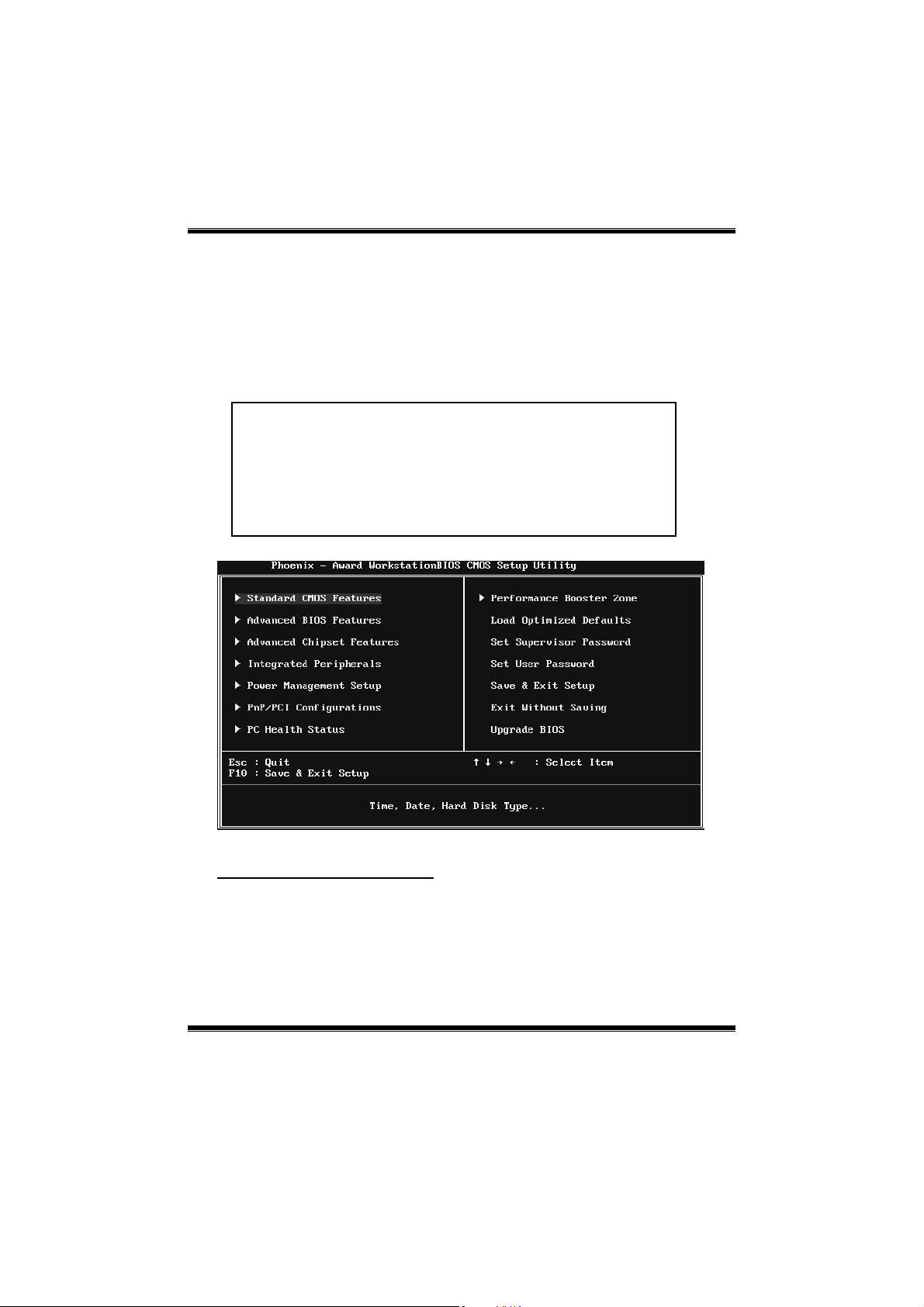
1 Main Menu
Once you enter Pho enix-Award BIOS™ CMOS Setup Utility, the Main Menu
will appear o n the screen. T he Main Menu allows you to select from several
setup f unct ions. Us e the arro w keys to select among the items and pr ess <Enter>
to accept and enter the sub-menu.
!! WARNING !!
For better system performance, the BIOS firmware is being
continuous ly updat ed. T he BIOS information descr ibed in
this manual (Figure 1, 2, 3, 4, 5, 6, 7, 8, 9) is for your
reference only. The actual BIOS information and settings on
board may be slightly different from this manual.
Figure 1: Main Menu
Standard CMOS Features
This submenu contains industry standard configurable options.
3
Page 5

GF7050-M2 SE/GF7025-M2 TE
Advanced BIOS Features
This submenu allows you to co nfigur e advanc ed features o f the BIOS.
Advanced Chipset Features
This submenu allows you to configure special chips et featur es.
Integrated Peripherals
This submenu allows you to configure certain IDE hard drive options and
Programmed Input/ Output features.
Power Management Setup
This submenu allows you to configure the power management features.
PnP/PCI Configurations
This submenu allows you to configure certain “Plug and Play” and PCI options.
PC Health Status
This submenu allows you to monitor t he hardware of yo ur syste m.
Performance Booster Zone
This submenu allo ws you to change CPU Vcore Voltage and CPU/PCI clock.
(However, we suggest you to use the default setting. Changing the voltage and
cloc k improp e rly may damag e the CP U or M/B!)
Load Optimized Defaults
This selection allows you to reload the BIOS when problem occ urs during
system booting sequenc e. These configurations are factory settings optimized
for this system. A confirmation message will b e displayed befo re d efaults are
set.
4
Page 6
GF7050-M2 SE/GF7025-M2 TE
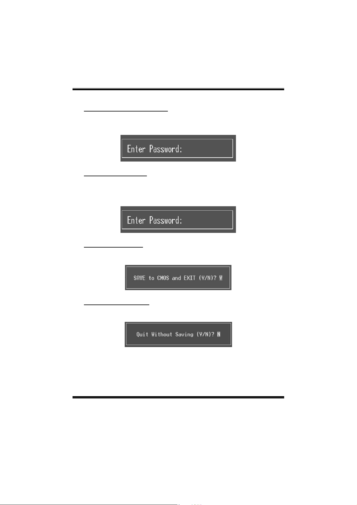
Set Supervisor Password
Setting the supervisor password will p rohibit everyone except the sup ervisor
from making c hanges using the CMOS Setup Util ity. You will be prompted with
to ent er a password.
Set User Password
If the Supervisor Password is not set, then the Us er Pass word will function in
the same way as the S upervisor Pass word. If the S uperviso r Password is set and
the Us er Pass word is set, the “User” will only be ab le to view co nfigurations b ut
will not be able to change them.
Save & Exit Setup
Save all configuration changes to CMOS (memory) and exit setup. Confirmation
message will be displayed before proceeding.
Exit Without Saving
Abandon all changes made during the current session and exit setup.
Confirmation message will be displayed before proceeding.
5
Page 7

GF7050-M2 SE/GF7025-M2 TE
Upgrade BIOS
This submenu allows you to upgrade bios.
6
Page 8
GF7050-M2 SE/GF7025-M2 TE
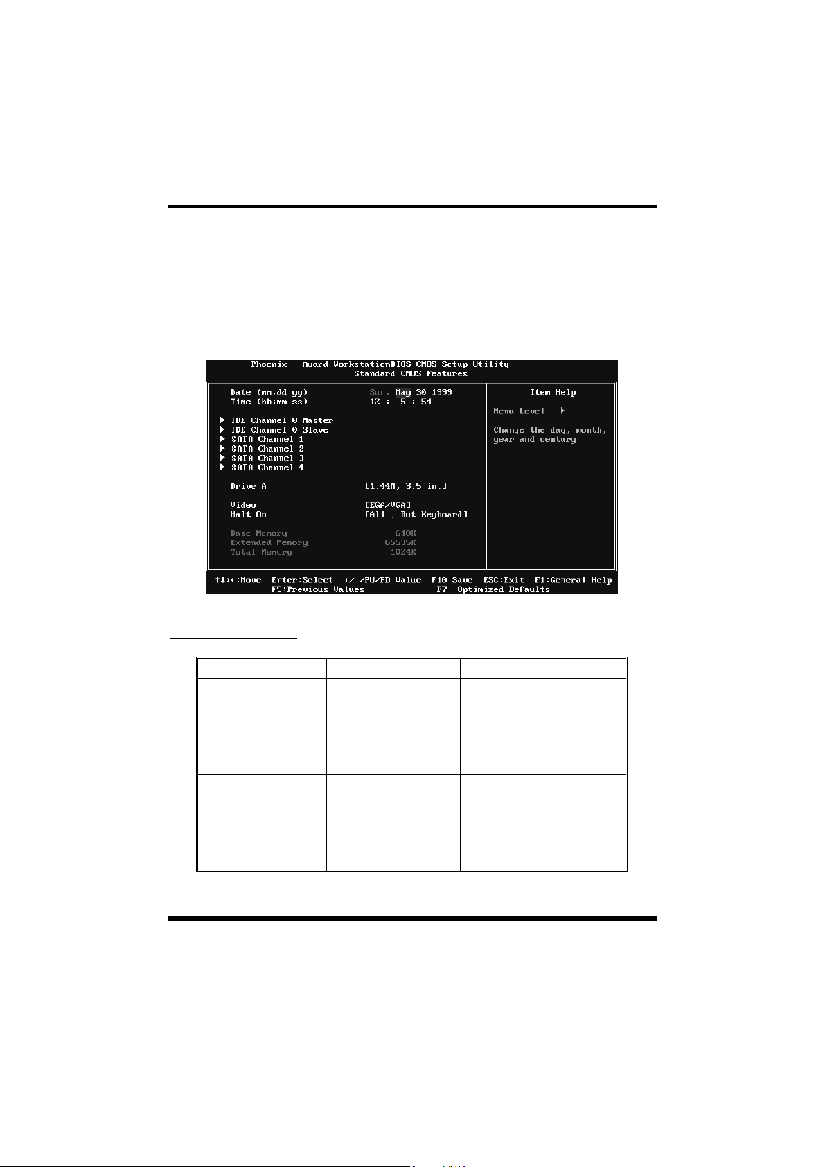
2 Standard CMOS Features
The items in Standard CMOS Setup Menu are divided into several categories.
Each cate gor y inc ludes no, one or more than one setup items. Us e the arrow
keys to highlight the item and then use the<PgUp> or <PgDn> keys to select the
value you want in each item.
Figure 2: Standard CMOS Setup
Main Menu Selections
This table sho ws the items and the available optio ns on the Main Menu.
Item Options Description
Date mm : dd : yy
Time hh : mm : ss
IDE Channel 0
Master
IDE Channel 0
Slave
Options are in its sub
Options are in its sub
menu.
menu.
Set the system date. Note
that the ‘Day’ automatically
changes when you set the
date.
Set the system internal
clock.
Press <Enter> to enter the
sub menu of detailed
options
Press <Enter> to enter the
sub menu of detailed
options.
7
Page 9

GF7050-M2 SE/GF7025-M2 TE
Item Options Description
SATA Channel 1~4
Drive A
Video
Halt On
Base Memory N/A
Extended Memory N/A
Total Memory N/A
Options are in its sub
menu.
360K, 5.25 in
1.2M, 5.25 in
720K, 3.5 in
1.44M, 3.5 in
2.88M, 3.5 in
None
EGA/ VG A
CGA 40
CGA 80
MONO
All Errors
No Errors
All, but Keyboard
All, but Diskette
All, but Disk/ Key
Press <Enter> to enter the
sub menu of detailed
options.
Select the type of floppy
disk drive installed in your
system.
Select the default video
device.
Select the situation in which
you want the BIOS to stop
the POST process and
notify you.
Displays the amount of
conventional memory
detected during boot up.
Displays the amount of
extended memory detected
during boot up.
Displays the total memory
available in the system.
8
Page 10
GF7050-M2 SE/GF7025-M2 TE
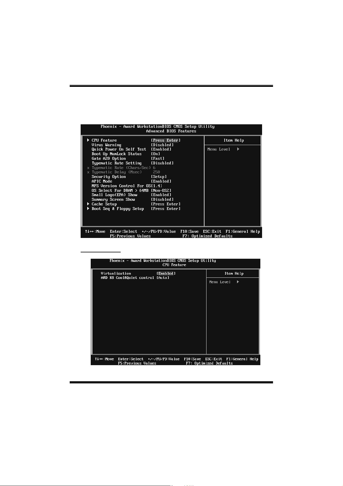
3 Advanced BIOS Features
Figure 3: Advanced BIOS Setup
CPU Feature
9
Page 11

GF7050-M2 SE/GF7025-M2 TE
Virtualiza tion
The item allows you control the Virtualization function.
The Choices: Enabled (default), Disabled.
AMD K8 Coo l&Quiet control
The item allows you select K8 Cool’n’Quiet control.
The Choices: Auto (default), Disabled.
Virus Warning
This option allows you to choose the VIR US Warning feature that is used to
protect the IDE Hard Disk boot sector. If this function is enabled and an attempt
is made to write to the boot secto r, BIOS will disp lay a warning message on the
screen and sound an alarm beep.
Disabled (default) Virus protectio n is disabled.
Enabled Virus protection is activated.
Quick Power On Self Test
Enabling this option will cause an abridged version of the Power On Self-Test
(POS T) to execut e after you power up the computer.
Disabled Normal POST.
Ena bled (default) Enable quic k POST.
Boot Up NumLock Status
Selec ts t he NumLock State after the system switch ed on.
The Choices:
On (def ault) Nump ad is number keys.
Off Numpad is arrow keys.
Gate A20 Option
Select if chipset or keyboard controller should control Gate A20.
Normal A pin in the keyboard controller controls G ateA20.
Fast (default) Lets chipset control Gate A20.
10
Page 12

GF7050-M2 SE/GF7025-M2 TE
Typematic Rate Setting
When a key is held down, the keystroke will repeat at a rate determined by the
keyboard controller. When enab led, the typematic rate and typematic delay can
be configured.
The Choices: Disabled (d efault ), Enabled.
Typematic Rate (Chars/Sec)
Sets the rate at whic h a keyst roke is r epea ted when yo u hold the ke y down.
The Choices: 6 (default), 8, 10, 12, 15, 20, 24, 30.
Typematic Delay (Msec)
Sets the delay time after the key is held down before it b egins to rep eat the
keystroke.
The Choices: 250 (default), 500, 750, 1000.
Security Option
This option will enable only individuals with pass words to bring the sys tem
online and/or to use the CMOS Setup Utility.
System: A pass word is required for the system to boot and is also
required to access the Setup Utility.
Setup (def ault): A pass word is required to access the S etup Utility only.
This will only apply if passwords are set from the S etup main menu.
APIC MODE
Selecting Enab led enab les APIC device mode reporting fro m t he BIOS to the
operating system.
The Choices: Enabled (default), Disabled.
MPS Version Control For OS
The BIOS supports version 1.1 and 1.4 of the Intel multiprocessor specification.
Selec t vers ion supported by the operation syste m r unning on this computer.
The Choices: 1.4 (default), 1.1.
11
Page 13

GF7050-M2 SE/GF7025-M2 TE
OS Select For DRAM > 64MB
A choice other than Non-OS2 is only used for OS2 systems with memory
exceeding 64MB.
The Choices: Non-OS2 (default), OS2.
Small Logo(EPA) Show
This item allows you to select whether the “Small Logo” shows. Enabled
(default) “Small Logo” shows when system boots up. Disabled No “Small
Logo” shows when system boots
The Choices: Enabled (default), Disabled.
Summary Screen Show
This item allows you to enab le/disable the summary sc reen. Summary screen
means system configuration and PCI device listing.
The Choices: Disabled (d efault ), Enabled.
Cache Setup
12
Page 14

GF7050-M2 SE/GF7025-M2 TE
CPU Internal Cache
Depending on the CPU/chipset in use, you may be able to increase memory
ac ces s tim e with this opt ion.
Enabled (default) Enable cache.
Disabled Disable cache.
External Cache
This option enables or disables “Level 2” secondary cache on the CPU, which
may improve performance.
Enabled (default) Enable cache.
Disabled Disable cache.
Boot Seq & Floppy Setup
This item allows you to setup boot sequence & Floppy.
13
Page 15

GF7050-M2 SE/GF7025-M2 TE
Removable Device Prior ity
Select Removable Boot Device Priority.
The Choices: Floppy Disks, Zip100, USB-FDD0, USB-FDD1, USB-ZIP0,
USB-ZIP1, LS 120.
Hard Disk Boot Priority
The BIOS will attempt to arrange the Hard Disk boot sequence automatically.
You can change the Hard Disk booting sequence here.
The Choices: Pri. Master, Pri. S lave, Sec. Master, Sec. Slave, USB HDD0, USB
HDD1, US B HDD2, and Bootable Add-in Cards.
14
Page 16

GF7050-M2 SE/GF7025-M2 TE
CD-ROM Boot Priority
The Choices: Pri. Master, Pri. Slave, Sec. Master, Sec. Slave, USB CDROM0,
USB CDROM 1.
First/Second/Third Boot Device
The BIOS will attempt to load the operating system in this order.
The Choices: Removable, Hard Disk, CDROM, Legacy LAN, Disabled.
Boot Other Device
When enabled, BIOS will try to load the operating system from other device
when it failed to load from the three devices above.
The Choices: Enabled (default), Disabled
Boot Up Floppy Seek
When enabled, System will test the floppy drives to determine if they have 40
or 80 tracks during boot up. Disabling this option reduces the time it takes to
boot-up.
The Choices: Enabled (default), Disabled.
15
Page 17

GF7050-M2 SE/GF7025-M2 TE
4 Advanced Chipset Features
This sub menu allows you to configure the specific features o f the chipset
installed on your system. This chipset manage bus speeds and access to system
memory resources, such as DRAM. It also coordinates communications with the
PCI bus. The d efault settings that came with yo ur system have been optimized
and t her efore s hou ld no t be changed unle ss you are s usp icious that t he settings
have been changed incorrectly.
Figure 4: Advanced Chipset Setup
iGPU Frame Buffer Control
This item allows you to control the iGPU frame buffer.
The Choices: AUTO (d efault), Manual.
Frame Buffer Size
This item allows you to choose the frame buffer size of on-chip VGA.
The Choices: 64M (default), 16M, 32M, 128M, 256M, Dis abled.
K8<->NB HT Speed
The Choices: AUTO (default), 1x, 2x, 3x, 4x, 5x.
16
Page 18

GF7050-M2 SE/GF7025-M2 TE
K8<->NB HT Width
The Choices: AUTO (d efault), ↓8↑8, ↓16↑16.
CPU Spread Spectru m
This item allows you to select the CPU Spread Spectrum function.
The Choices: 0.50% H. Kiss Cntr, 0.50% H.Kiss Down, 0.75% H.Kiss Cntr,
0.75% H. Kiss Do wn, Disabled (default).
PCIE Spread Spectrum
This item allows you to select t he PCIE Spread Spectrum function.
The Choices: Disabled (d efault ), Linear Do wn.
SATA Spread Spectrum
This item allows you to select the S ATA Spread Spectrum function.
The Choices: Disabled (d efault ), Linear Do wn.
iGPU Spread Spectrum
This item allows you to select the iGPU Spread Spectrum function.
The Choices: Disabled (default), 1%, 2%, 3%.
SSE/SSE2 instructions
This item allows you to enable/disable SSE/SSE2 instruction.
The Choices: Enabled (default), Disabled.
System BIOS Cacheable
Selecting the “Enab led” option allows cac hing of the s ystem BIOS ROM at
F0000h-FFFFFh, which is able to improve the system performance. However,
any p rograms that attempts to write to this memory block wi ll caus e conflicts
and result in s ystem errors.
The Choices: Disabled (d efault ), Enabled.
17
Page 19

GF7050-M2 SE/GF7025-M2 TE
5 Integrated Peripherals
Figure 5. Integrated Peripherals
IDE Function Setup
Highlight the “Press Enter” label next to the “IDE Function Setup” label and
press enter key will take you a s ubmenu with the following options:
18
Page 20

GF7050-M2 SE/GF7025-M2 TE
MCP Storage Config
SATA Operation Mode
This option allows you to choose SATA function.
The Choices: IDE (default), RAID, AHCI, Linux AHCI.
SATA Pr i-/Sec - Master/Slave RAID
This option allows you to enable or disable SATA Primary/Secondary RAID.
The Choices: Disabled (default), Enabled.
On-chip IDE Channel 0
The motherboard chipset contains a PCI IDE interface with support for two
IDE channels. Select “Enabled” to activate the first and/or second IDE interface.
Select “Disabled” to deactivate an interface if you are going to install a primary
and/or secondary add-in IDE interface.
The Choices: Enabled (default), Disabled.
Primary Master/Slave PIO
The IDE PIO (P rogrammed Input / Output) fields let you set a PIO mode (0-4)
for each of the IDE devices that the onboard IDE interface supports. Modes 0
to 4 will inc rea se per for ma nce pro gre ssiv e ly. In Auto mode, t he s yst em
automatically determines the best mode for each device.
The Choices: Auto (default), Mode0, Mode1, Mode2, Mode3, Mode4.
19
Page 21

GF7050-M2 SE/GF7025-M2 TE
Primary Master/Slave UDMA
Ultra DMA function can be implemented if it is supported by the IDE hard
drives in your system. As well, your operating environment requires a DMA
driver (Windows 95 or OSR2may need a third party IDE bus master driver). If
your hard drive and your system software both support Ultra DMA, select Auto
to enable BIOS support.
The Choices: Auto (default), Disabled.
IDE DMA Transfer Access
This item allows you to enable or disable the IDE DMA transfer access.
The Choices: Enabled (default), Disabled.
Serial-AT A Controller
This item allows you to enable or disable the Serial ATA function.
The Choices: Enabled (default), Disabled.
IDE Prefetch Mode
The “onboard” IDE drive interfaces supports IDE prefetch function for faster
drive access. If the interface on your drive does not support prefetching, or if
you install a primary and/or secondary add-in IDE interface, set this option to
“Disabled”.
The Choices: Enabled (default), Disabled.
IDE HDD Block Mode
Bloc k mode is also called block transfer, mult ip le c omm ands, or mult ip le
sectors read / write. If your IDE hard drive supports block mode (most new
drives do), select Enabled for automatic detection of the optimal number of
block mode (most new drives do), select Enabled for automatic detection of the
optimal number of block read / write per sector where the drive can support.
The Choices: Enabled (default), Disabled.
20
Page 22

GF7050-M2 SE/GF7025-M2 TE
Onboard Device
Highlight the “Press Enter” lab el next to the “Onboard Device” label and press
the enter key will take you a submenu with the fo llowing options:
HD Audio
This option allows you to control the onboard HD audio.
The Choices: Auto (default), Disabled.
MAC LAN
This option allows you to control the onboard LAN.
The Choices: Auto (default), Disabled.
MAC Media Interface
T his o ptio n allow s you to select the MAC media interface..
The Choices: Pin Strap (default), MII, RGMII.
Onboard LAN Boot ROM
This item allows you to enable or disable the Onboard LAN Boot ROM.
The Choices: Disabled (default), Enabled.
21
Page 23

GF7050-M2 SE/GF7025-M2 TE
Onboard SuperIO Device
Press Enter to configure the Super I/O device.
Onboard FDC Controller
Select enabled if your system has a floppy disk controller (FDC) insta lled on
the system board and you wish to use it. If you installed another FDC or the
system uses no floppy drive, select disab led in this field.
The Choices: Enabled (default), Disabled.
Onboard Serial Port 1
Select an address and corresponding interrupt for the first and second serial
ports.
The Choices: 3F8/IRQ4 (default), Disabled, 2F8/IRQ3, 3E8/IRQ4, 2E8/IRQ3,
Auto.
Onboard Parallel Port
This item allows you to determine access onboard parallel port controller with
which I/O Address.
The Choices: 378/IRQ7 (default), 278/IRQ5, 3BC/IRQ7, Disabled.
22
Page 24

GF7050-M2 SE/GF7025-M2 TE
Parallel Port Mode
This item allows you to determine how the parallel port should function. The
default value is SPP.
The Choices:
SPP (def au lt) U sin g Parallel port as Sta ndard Printer P ort.
EPP Usin g P ar alle l P ort as Enh anced P ar alle l P ort .
ECP U sin g Para llel p ort as Extended Capabilit ies Port.
ECP+ EPP Usin g P aralle l port a s ECP & EPP mod e.
ECP Mode Use DMA
Select a DMA Channel for the port.
The Choices: 3 (default), 1.
Onboard GPU
This item allows you to control the onboard GPU.
The Choices: Auto (default), Always Enable.
Init Display First
This item allows you to decide to active whether PCI Slot or on-chip VGA first.
The Choices: PCIEx (default), PCI Slot, Onboard.
OnChip USB
This option sho uld be enab led if your system has a US B installed on the system
board. You may need to dis able this feature if you add a higher performance
controller.
The Choices: V1.1+V2.0 (default), Disabled, V1.1
USB Memory Type
This option allows you to choose the US B memory type.
The Choices: SHADOW (default), Base Memory(640K).
23
Page 25

GF7050-M2 SE/GF7025-M2 TE
USB Keyboard/Storage Su pport
This item allows yo u to enable or dis able the USB Keyboard / stora ge Legacy
Support.
Enabled (default) Enable USB Keyboard / storage Support.
Disabled Disable USB Keyboard/ storage Support.
USB Mouse Support
This item allows yo u to enable or dis able the USB mo us e Legacy Support.
Enabled (default) Enable USB mouse Support.
Disabled Disable USB mouse Support.
HDMI Audio
This item allows you to control the audio function of HDMI.
The Choices: Auto (default), Disabled.
24
Page 26

GF7050-M2 SE/GF7025-M2 TE
6 Power Management Setup
The Power Management Setup Menu allows you to configure your system to
utilize energy conservation and power up/power down features.
Figure 6. Power Manageme nt Se tup
ACPI Function
This it em displays the s tatus of the Ad vanced Co nfiguration and Po wer
Management (ACPI).
The Choices: Enabled (default), Disabled.
ACPI Suspend Type
The item allo ws yo u to select the suspend type under the ACPI operating
system.
The Choices: S1 (POS) (default ) Power on Suspend
S3 (STR) Suspend to RAM
S1 & S3 POS+STR
25
Page 27

GF7050-M2 SE/GF7025-M2 TE
Power Management
This category allows you to select the power s aving method and is d irectly
related to the fo llo w ing mod es :
1. HDD P o wer Do wn.
2. Suspend Mode.
There are three options of Power Management, three of which have fixed mod e
settings
Min. Power Saving
Minimum power management.
Suspend Mode = 1 hr.
HDD Power Down = 15 min
Max. Power Saving
Maximum power management only available for sl CPU’s.
Suspend Mode = 1 min.
HDD Power Down = 1 min.
Use r De fi ne (d efault)
Allow yo u to set each optio n individually.
When you choose user define, you can adjust each of the item from 1 min. to 1
hr. except for HDD Power Down which ranges from 1 min. to 15 min.
Video Off Method
This option determines the manner when the monitor goes blank.
V/H SYNC+Blank
This selection will cause the system to turn off the vertical and horizo ntal
synchronization ports and write blanks to the video buffer.
Blank Screen
This option o nly writes blanks to the video b uffer.
DPM S Suppo rt (default)
Initial display power management s ignaling.
HDD Power Down
Whe n enab led, the hard -disk dr ives will power down after a set time of system
inactivity. All other devices remain active.
The Choices: Disabled (default), 1 Min, 2 Min, 3 Min, 4 Min, 5 Min, 6 Min, 7
Min, 8 Min, 9 Min, 10 Min, 11 Min, 12 Min, 13 Min, 14 Min, 15Min.
26
Page 28

GF7050-M2 SE/GF7025-M2 TE
HDD Down In Suspend
This option allows you to enabled or disabled the HDD power down function in
susp end mode.
The Choices: Disabled (d efault ), Enabled
Soft-Off by PBTN
This item determines the behavior of system power button. Instant off turn off
the po wer i mmed iately, and Delay 4 Sec. will require you to pres s and ho ld the
power button for 4 s econds to cut off the sys tem po wer.
The Choices: Delay 4 Sec, Instant-Off (default).
WOL(PME#)/ From Soft-Off
This item allows you to enab le o r dis able Wake On LAN from Soft-Off
function.
The Choices: Disabled (d efault ), Enabled.
WOR(RI#) Fro m Soft-O ff
This item allows you to enab le o r dis able Wake On Ring fro m Soft-Off function.
The Choices: Disabled (d efault ), Enabled.
USB Resume From S3/S4
This item allows yo u to enable or dis abled the US B res ume f rom S 3/S4
function.
The Choices: Disabled (d efault ), Enabled.
Power-On by Alarm
This function is for setting date and time for your computer to boot up. When
enabled, you can choose the date and time to boot up t he s ystem.
The Choices: Disabled (d efault ), Enabled.
27
Page 29

GF7050-M2 SE/GF7025-M2 TE
Date (of Month) Alarm
You c an c hoose which mo nth the system will boot up.
Time (hh:mm:ss) Alarm
You c an c hoose t he s yst em boot up time, input ho ur, minute and seco nd to
specify.
Note : If yo u have c hange the setting, yo u must le t the system boo t up unt il it
goes to the o perating syste m, before this function will work.
HPET Support
This option allows you to disab led or enab les the High Precisio n Event Timer.
The Choices: Enabled (default), Disabled.
POWER ON Function`
This item allows you to choose the power on method.
The Choices: Button Only(d ef ault), Pass word, Hot Ke y, Mous e Mo ve, Mo use
Click, Any Key, Keyboard 98.
KB Power ON Password
Input password and press Enter to set the Keyboard power on password.
Hot Key Power ON
Choos e the Hot Key co mbinatio n to boot up the s ystem.
The Choices: Ctrl-F1(default), Ctrl-F2, Ctrl-F3, Ctrl-F4, Ctrl-F5, Ctrl-F6,
Ctrl-F7, Ctrl-F8, Ctrl-F9, Ctrl-F10, Ctrl-F11, and Ctrl-F12.
PWRON After PWR-Fail
This setting specifies ho w your s ystem should behave after a power fail or
interrupts occurs. By choos ing off wil l leave the co mputer in the power o ff state.
Choos ing On will reboot the computer. Former-S ts will restore the system to the
status befo re po wer failure or interrupt occ urs.
The Choices: Off (default), On, Former-Sts.
28
Page 30

GF7050-M2 SE/GF7025-M2 TE
7 PnP/PCI Configurations
This section describes configuring the PCI bus system. PCI, or Personal
Computer Int erconnect, is a s yst em whic h allows I/O d evices to op erate at
speeds nearing the speed of the CPU itself uses when c ommunicat ing with its
own special components. This section covers some very technical items and it is
strongly recommended that only experienced users should make any changes to
the default settings.
Figure 7: PnP/PCI Configurations
Reset Configuration Data
The s ystem BIOS suppo rts the P nP feature which requires the syst em to record
whic h resources ar e ass igned a nd pro t ects reso urc es from c onflict.
Every periph eral device has a nod e, whic h is cal led ESCD. This node records
whic h reso urc es ar e ass igned to it. T he s ys tem needs to reco rd and up date ESCD
to the memory locations. These locations are reserved in the system BIOS. If the
Disabled (default) option is chosen, the system‘s ESCD will update only when
the ne w configur ation varies fro m the last one. If the Enable d opt ion is c hos en,
the system is forced to update ESCDs and then is automatically set to t he
“Disabled” mode.
29
Page 31

GF7050-M2 SE/GF7025-M2 TE
The above settings will be shown on the screen only if “Manual” is chosen for
the resourc es contro lled by functio n.
Legac y is the term, whic h s ignifies that a resource is ass igned to the ISA Bus
and provides non-PnP ISA add-on cards. PCI / ISA PnP signify that a resource
is assigned to the PCI Bus or provides for ISA PnP add-on cards and
peripherals.
The Choices: Disabled (d efault ), Enabled.
Resources Controlled By
By Choos ing “Auto(ESCD)” (default), the system BIOS will detect the system
resources and automatically assign the relative IRQ and DMA channel for each
perip heral. By Choosing “Manual”, the us er will need to ass ign IRQ & DMA for
add-on cards. Be sure that there are no IRQ/DMA and I/O port conflicts.
The Choices: Auto (ESCD) (default), Manual.
IRQ Resources
This sub menu will allow yo u to assign each system interrupt a type, d epending
on the type of devic e us ing the inter rupt. When you press the “Press Ente r” tag,
you will be direc ted to a sub menu that will allow you to configure the syst em
interrupts. This is only co nfigurable when “Resources Co ntro lled By” is set to
“Manual”.
IRQ-5 ass igned to PCI Devic e
IRQ-7 ass igned to PCI Devic e
IRQ-9 ass igned to PCI Devic e
IRQ-10 ass igned to PCI Devic e
IRQ-11 ass igned to PCI Device
IRQ-14 ass igned to PCI Device
PCI / VGA Palette Snoop
Some old graphic controllers need to “s noop” on the VGA palette and then map
it to their disp lay as a way to provide boot info rmat ion and VGA compatibility.
This item allows such snooping to take p lace.
The Choices: Disabled (d efault ), Enabled
Ma xi mu m Pa ylo a d Size
Set t he maximum p ayload s ize for Transac tio n pac kets (TLP).
The Choice: 4096 (default.), 128, 256, 512, 1024, 2048.
30
Page 32

GF7050-M2 SE/GF7025-M2 TE
8 PC Health Status
Figure 8: PC Health Status
Smart Fan Option
31
Page 33

GF7050-M2 SE/GF7025-M2 TE
CPU Smart Fan
Smar t Fan Calibration
PWM Duty Off<℃>
PWM Duty Start<℃>
Start PWM Value
Smart Fan Slope
T his it em a llows you to control the CPU Fan .
The Choices: Disabled (default), Auto, 4-pin, 3-pin..
Choose this item and then the BIOS will auto test and detect the CPU fan
functions and show CPU fan speed.
If the CPU Temperature is lower than the set value, FAN will turn off.
The Choices: Min=0,.Max=127, Key in a DEC number.
CPU fan starts to work under smart fan function when arrive this set
value.
The Choices: Min=0,.Max=127, Key in a DEC number.
Whe n CPU temperature arrives to t he set value, the CPU f an will work
under Smart Fan Function mode. The range is from 0~127, with an
interval of 1.
The Choices: Min=0,.Max=127, Key in a DEC number.
Increasing the value of s lope PW M will raise the speed of CPU fan.
The Choices: Min=1,.Max=127, Key in a DEC number.
Shutdown Temperature
This item allows you to set up the CPU s hutdown Temp erature. This item is
only effective under Windows 98 ACPI mode.
The Choices: Disabled , 60℃/ 140℉, 65℃/ 149℉ , 70℃/ 158℉, 75℃/ 167℉,
80℃/ 176℉ (default), 85℃/ 185℉, 90℃/ 167℉.
Show H/W Monitor in POST
If you computer contains a monitoring s ystem, it will show PC health status
during POST stage. The item offers several different delay times.
The Choices: Enabled (default), Disabled.
32
Page 34

GF7050-M2 SE/GF7025-M2 TE
CPU Vcore, Chipset Volt, +3.3V, +5.0V, +12.0V, DDR Voltage,
HT Voltage, Voltage Battery
Detect the sys tem’s voltage status automat ically.
CPU Temp
This field disp lays the c urrent te mperature of CPU.
Current CPU FAN Speed
This field disp lays the c urrent s peed of CP U fan.
Current SYS FAN Speed
This field disp lays the c urrent speed S YSTEM fan.
33
Page 35

GF7050-M2 SE/GF7025-M2 TE
9 Performance Booster Zone
VCore Voltage
This item allows you to adjust the CPU Vcore voltage.
The Choices: Default (default), +3.3%, +6.6%, +10%
Memory Voltage
This item allows you to adjust the memory voltage.
The Choices: Default (default), 2.000V, 2.045V, 2.100V
CPU Frequency
This item allows you to select the CPU Frequency.
The Choices: 200 (default); Min=200, Max=450, Key in a DEC number.
34
Page 36

GF7050-M2 SE/GF7025-M2 TE
DRAM Configuration
Timing Mode
T his it em a llows you to choose to ma nua lly or aut omatically r egula te t he DDR
Timing.
The Choices: Auto ( default), MaxMemClk.
Memory Clock Value OR Limi
The Choices: DDR 400 (default), DDR 533, DDR 667, DDR 800.
DQS Training Control
The Choices: Perform DQS, Skip DQS (default).
CKE base power down mode
The Choices: Enabled (default), Disabled.
CKE based power down
The Choices: Per Channel (default), Per CS.
Memclock tri-stating
The Choices: Disabled (default), Enabled.
35
Page 37

GF7050-M2 SE/GF7025-M2 TE
Memory Hole Remapping
The Choices: Enabled (default), Disabled.
Auto Optimize Bottom IO
The Choices: Enabled (default), Disabled.
Bottom of [31:24] IO space
The Choices: E0 (default); Min=0000, Max=00FF, key in a HEX number.
Bottom of UMA DRAM [31:24]
The Choices: FC (default); Min=0000, Max=00FC, key in a HEX number.
CAS Latency
The CAS Latency (tCL) is the time (in number of clock cycles) that elapses
after the memory controller sends a request to read a memory location and
before the data is sent to the module's output pins.
The Choices: Auto ( default), 2.0, 3.0, 4 .0, 5.0, 6.0.
DRAM Command Mode
This item allows you to choose the DRAM command mode.
The Choices: Auto ( default), 1T, 2T .
DDRII Timing Item
The Choices: Disabled (default), Enabled.
TwTr Command De lay
The Choices: 3 bus clocks (default), 1 bus clocks, 2 bus clocks.
Trfc0 for DIMM0
The Choices: 75ns (default), 105ns, 127.5ns, 195ns, 327.5ns.
Trfc1 for DIMM1
The Choices: 75ns (default) , 105ns, 127.5ns, 195ns, 327.5ns.
Trfc2 for DIMM2
The Choices: 75ns (default) , 105ns, 127.5ns, 195ns, 327.5ns.
Trfc3 for DIMM3
The Choices: 75ns (default) , 105ns, 127.5ns, 195ns, 327.5ns.
<Twr> Write Recovery Time
The Choices: 6 bus clocks (default), 3 bus clocks, 4 bus clocks, 5 bus clocks.
36
Page 38

GF7050-M2 SE/GF7025-M2 TE
<Trtp> Precharge Time
The Choices: 3 clocks (default), 2 clocks.
<Trc> Row Cycle T ime
The Choices: 26 bus clocks (default), 11-25 bus clocks.
<Trc d> RAS to C AS R/W Delay
The Choices: 6 clocks (default), 3 clocks, 4 clocks, 5 clocks.
<Trrd> RAS to RAS Delay
The Choices: 5 clocks (default), 2 clocks, 3 clocks, 4 clocks.
<Trp> Row Precharge Time
The Choices: 6 clocks (default), 3 clocks, 4 clocks, 5 clocks.
<Tras> Minimum RAS Active T
The Choices: 18 bus clocks (default), 5-17 bus clocks.
PCIE Clock
This item allows you to select the PCIE clock.
The Choices: 100Mhz (default), 101Mhz~150Mhz.
37
 Loading...