

Page 1

GF7025-M2 TE/GF7050-M2 SE Set up Manual
FCC Inf or m at ion and Copyri ght
This equipment has been tested and found to comply with the limits of a Class
B digital device, purs uant to Part 15 of the FCC Rules. T hese limits are designed
to provide reasonable protec tion ag ainst harmful interfe rence in a residential
installation. T his equipment generates , uses, and can radiate radio frequency
energy and, if not ins talled and used in accordance with the instructions, may
cause harmful interference to radio communications. There is no guarantee
that i nterference wil l not occur in a pa r ticu la r ins ta llatio n .
The ven do r ma kes no represe n tatio ns o r wa r ra n ties wi th respec t t o the
contents here and s pecially disclaims any implied warranties of merchantability
o r fi tness fo r any p urp os e . Fu rthe r t he ve ndo r res e rves the ri g ht to r ev ise th is
publication and to make changes to the contents here without obligation to
notify any party beforehand.
D uplic a tion of this publicatio n , in pa rt o r in wh ol e, is no t allowed without fi rst
obtaining the vendor’s approval in writing.
The content of this user’s manual is subject to be changed without notice and
we will not be responsible for a ny mis takes found i n this user’s manual. A ll the
brand and produc t names are trademarks of their respective companies.
Page 2

Table of Contents
Chapter 1 : In tro d u c ti o n.....................................................3
1.1 Before You Start...................................................................3
1.2 Package Checklist................................................................3
1.3 Motherboard Features..........................................................4
1.4 Rear Panel Connectors.......................................................... 5
1.5 Mo t he r bo ar d Layou t............................................................6
Chapter 2 : Hardware Ins tallation........................................7
2.1 Installing Ce ntral Proce ssing Unit (CPU)................................ 7
2.2 FAN Heade rs........................................................................9
2.3 Installing System Memory.....................................................10
2.4 Con necto rs a nd Slo ts............................................................12
Chapter 3 : H e ad ers & Ju mp er s S etup.................................14
3.1 How to Setup Ju mper s..........................................................14
3.2 Det ail Settin gs.....................................................................14
Chapter 4 : RA ID Fu n c ti o n s...............................................21
4.1 Operation System................................................................21
4.2 Raid Array s.........................................................................21
4.3 How RAI D Work s.................................................................21
Chapter 5 : U s eful Help.....................................................25
5.1 Driver Instal latio n Note.......................................................25
5.2 Award BIOS Bee p Code........................................................26
5.3 Extra Informati on ................................................................26
5.4 Troubleshooting...................................................................27
Appenden cies: S PEC In Other L an g u ag e.............................28
German................................................................................................28
France..................................................................................................30
Italian..................................................................................................32
Spanish................................................................................................34
Portuguese ...........................................................................................36
Polish...................................................................................................38
Russian ................................................................................................40
Arabic..................................................................................................42
Japanese..............................................................................................44
Page 3
CHAPTER 1: INTRODUCTION
GF7025-M2 T E/GF7050-M2 SE
1.1 B
EFORE YOU START
Tha nk you for choosing our product. Befo re yo u start ins talling the
mo therboa rd, plea se make su re you follo w the ins tructio ns belo w:
Prepare a dry and stable working environment with
s uf ficie nt ligh ting .
Always disconnect the computer from power outlet
be fo re ope ration .
Befo re yo u take the m o the rboa rd o u t from a n ti-s ta t ic
bag, ground yourself properly by touching any safely
grounded ap plian ce, o r use grounded wris t s trap to
remove the static charge.
Avo id tou ch ing the com po ne nts o n mo the rboa rd o r the
rea r side of the boa rd unless ne cessary. Hold the bo ard
on the edge , do not try to be nd or flex the board.
Do no t lea ve any unfas tene d sma ll pa rts inside the
case after installation. Loose parts will cause short
circuits which ma y damage the equipment.
Keep the computer from dangerous area, such as heat
sou rce, humid a ir and wa ter.
1.2 PACKAGE CHECKLIST
HDD Cable X 1
Se ria l ATA Cab le X 1
Rear I/O Panel for ATX Case X 1
I ns talla tion Gu ide X 1
Fu lly Se tup D rive r C D X 1 (fu ll ve rsion manua l f iles ins ide )
FDD Cable X 1 (optional)
Se ria l ATA Po we r Cab le X 1 (o ptio nal)
USB 2.0 Cable X1 (optional)
S/P DI F ou t Ca ble X 1 (op tiona l)
Note: The package contents may differ by area or your motherboard version.
3
Page 4
Motherboard Manual
y
r
1.3 MOTHERBOARD FEATURES
GF7025- M2 T E GF7050- M2 S E
Socket AM2
AM D Athlon 64 / At hlon 64 FX / Athlon 64 x2 /
CPU
FSB
Chipset GeForce 7025/NF630a GeForce 7050/NF630a
Super I/O
Main
Memory
Graphics
IDE
SA TA II
LAN
Sound
Slots
4
Sempron processors
AM D 64 Architectur e enables 32 and 64 bit
computing
Supports Hyper Transport and Cool=n=Quiet
Supports up to 1 GHz Bandwidth
Support HyperTransport
ITE 8716F
Provides the most commonl
I/O functionalit y.
Low Pin Count Interface
Environment Control initiatives,
H/W Monitor
Fan Speed Controller
ITE's "Smart Guardian" function
DDR2 DIMM Slots x 2
Max Memory Capacity 4GB
Eac h DIMM supports 256MB/512MB/1GB/ 2GB
DDR2
Dual Channel Mode DDR2 memory module
Supports DDR2 533 / 667 / 800
Regist ered DIMM and ECC DIMM is not
supported
Int egrated i n GeForce 7025/NF630a Chi pset
Max Shared Video Memory is 512MB
Integrated IDE Controller
Ultra DMA 33 / 66 / 100 / 133 Bus Master Mode
supports PIO Mode 0~ 4,
Integrated Serial ATA Controller
Data transfer rates up to 3 Gb/s.
SATA Version 2.0 specification compliant.
Realtek RTL 8201CL
10 / 100 Mb/s aut o negotiation
Half / Full duplex capability
ALC662
5.1 channels audio out
High Defi nition Audio
PCI s lot x2 PCI s lot x2
PCI Express x16 slot x1 PCI Express x16 slot x1
us e d l egacy Supe
Socket AM2
AM D Athlon 64 / At hlon 64 FX / Athlon 64 x2 /
Sempron processors
AM D 64 Architectur e enables 32 and 64 bit
computing
Supports Hyper Transport and Cool=n=Quiet
Supports up to 1 GHz Bandwidth
Support HyperTransport
ITE 8716F
Provides the most c ommonly used legac y Super
I/O functionalit y.
Low Pin Count Interface
Environment Control initiatives,
H/W Monitor
Fan Speed Controller
ITE's "Smart Guardian" function
DDR2 DIMM Slots x 2
Max Memory Capacity 4GB
Eac h DIMM supports 256MB/512MB/1GB/ 2GB
DDR2
Dual Channel Mode DDR2 memory module
Supports DDR2 533 / 667 / 800
Regist ered DIMM and ECC DIMM is not
supported
Int egrated i n GeForce 7050/NF630a Chi pset
Max Shared Video Memory is 512MB
Integrated IDE Controller
Ultra DMA 33 / 66 / 100 / 133 Bus Master Mode
supports PIO Mode 0~ 4,
Integrated Serial ATA Controller
Data transfer rates up to 3 Gb/s.
SATA Version 2.0 specification compliant.
Realtek RTL 8201CL
10 / 100 Mb/s aut o negotiation
Half / Full duplex capability
ALC662
5.1 channels audio out
High Defi nition Audio
Page 5
GF7025-M2 T E/GF7050-M2 SE
GF7025- M2 T E GF7050- M2 S E
Fl oppy c onnect or x1 Fl oppy c onnector x1
Printer Port connect or x1 Printer Port connect or x1
IDE C onnector x1 IDE Connector x1
SA TA Con nect or x4 SATA C onnect or x4
Front Panel Connector x1 Front Panel Connector x1
Front Audio Connector x1 Front Audio Connector x1
On Board
Connector
Back Panel
I/O
Board Size 190 mm (W) x 244 mm(L) 190 mm (W) x 244 mm(L)
Special
Features
OS S upport
CD- in C onnec tor x1 C D-i n Connector x1
S/PDIF out connector x1 S/PDIF out connector x1
CP U Fa n header x1 C PU F an header x1
Sys tem F an header x1 S ystem Fan hea de r x1
CMOS clear header x1 CMOS clear header x1
USB connector x3 USB c onnector x3
S e ri al port Conn ect or x1 S e ri al port C onnect or x 1
Power Connector (24pin) x1 Power Connector (24pin) x1
Power Connector (4pin) x1 Power Connector (4pin) x1
PS/2 Keyboard x1
PS/2 Mouse x1
VGA port x1
DVI -D port x1
LAN port x1
USB Port x4
Audio Jack x3
RAID 0 / 1 / 5 / 0+1 support RAID 0 / 1 / 5 / 0+1 support
Windows XP / VISTA
Biostar Reserves the right to add or remove
support for any OS With or without notice.
PS/2 Keyboard x1
PS/2 Mouse x1
VGA port x1
DVI -D port x1
LAN port x1
USB Port x4
Audio Jack x3
Windows XP / VISTA
Biostar Reserves the right to add or remove
support for any OS With or without notice.
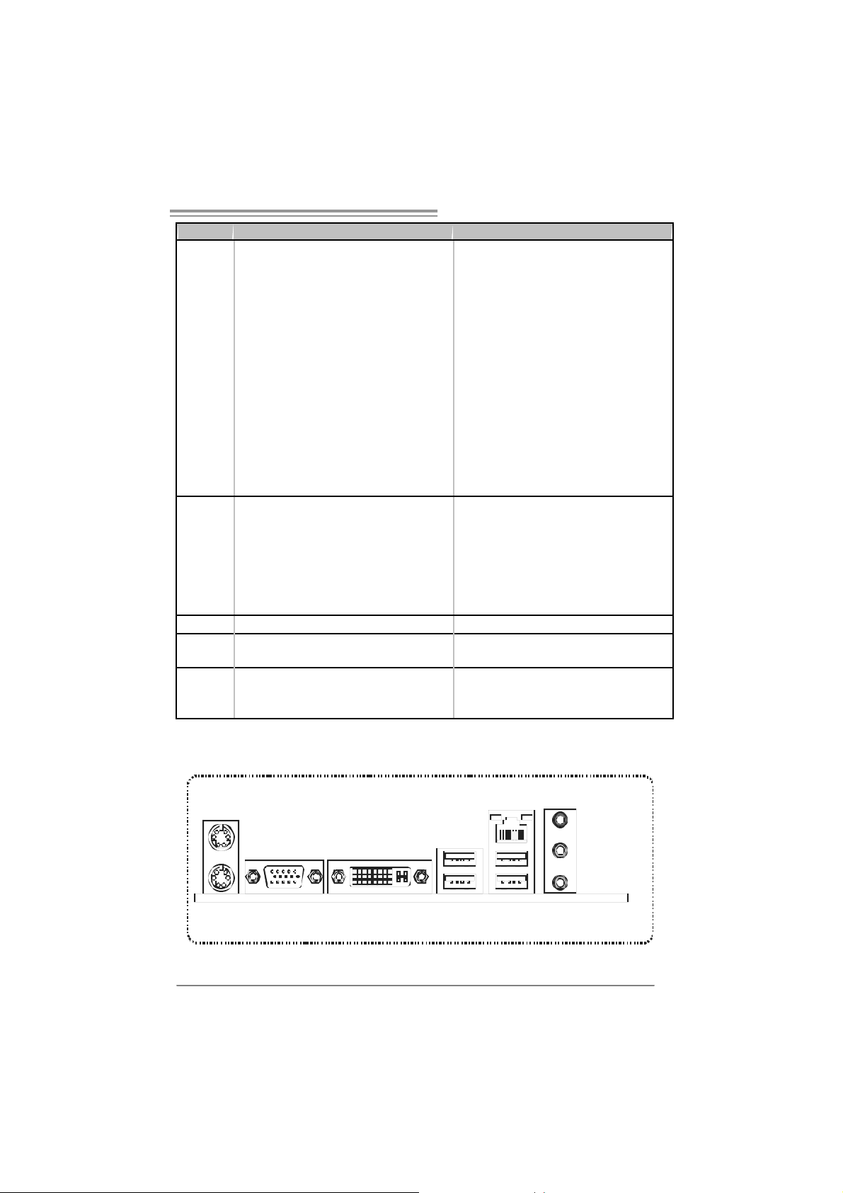
1.4 REAR PANEL CONNECTORS
PS/ 2
Mouse
PS/2
Keyboard
VGA
DVI-D
USBX2USBX2
LAN
Li n e In/
Surround
Li n e Out
Mi c In 1/
Bass/ Center
5
Page 6
Motherboard Manual
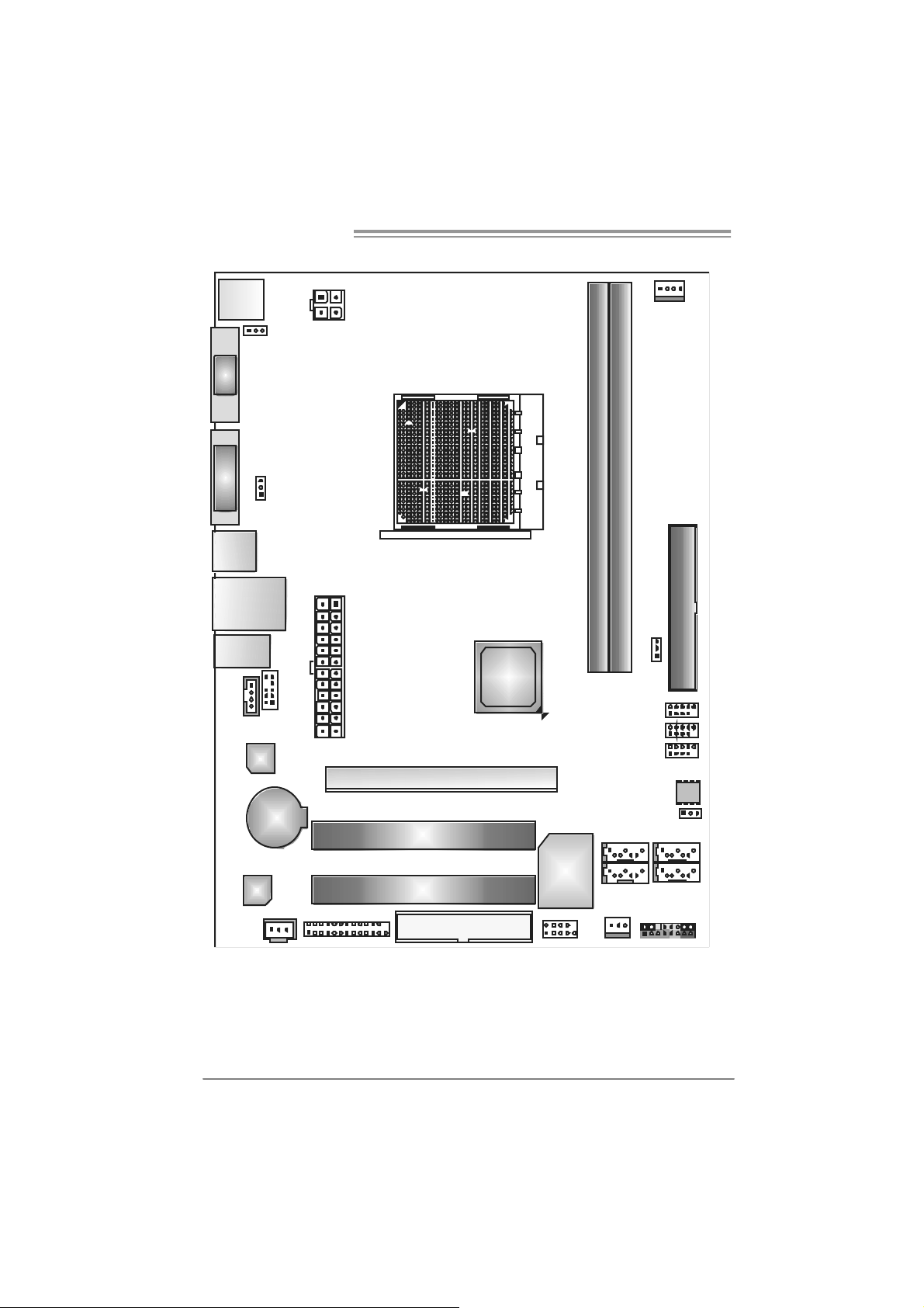
1.5 MOTHERBOARD LAYOUT
JKB MS1
JKBMSPWR1
VGA
DVI-D
JUSBPWR1
JUSB1
JUSBLAN1
JAUDIO1
JCDIN1
JAUDIOF1
LAN
BAT1
JATXPWR4
JATXPWR1
PCI-EX16
PCI1
GeForce
7025/7050
aNF630
Socket A M2
JCFAN1
DIMM A1
DIMM B1
IDE1
JUS BPWR2
JUSB3
JUSB2
JUSB4
BI OS
JCMOS1
SATA4SATA3
SATA2
JPANEL1
6
Codec
JSPDIF_OUT1
Note: represents the 1■
JPRNT1
PCI2
FDD1
st
pin.
JCOM1
Supe r I/O
SATA1
JSFAN1
Page 7
GF7025-M2 T E/GF7050-M2 SE
CHAPTER 2: HARDWARE INS TALLATION
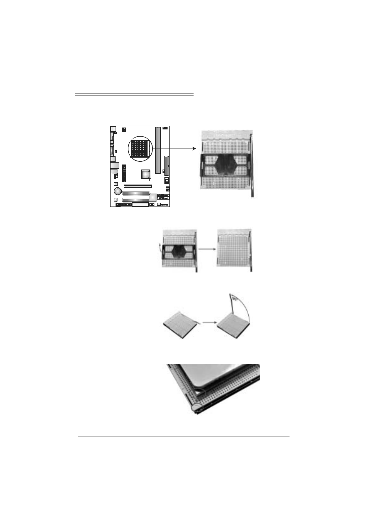
2.1 INSTALLING CEN TRAL PROCESSING UNIT (CPU)
Step 1: Remove the socket protection cap.
Step 2: Pull the l ever toward direction A from the socket and then rai se the
lever up to a 90-degree angle.
Step 3: Look for the white triangle on socket, and the gold triangle on
CPU should point towards this white triangle. The CPU will fit onl y
in th e cor r ec t or i en tatio n.
7
Page 8
Motherboard Manual
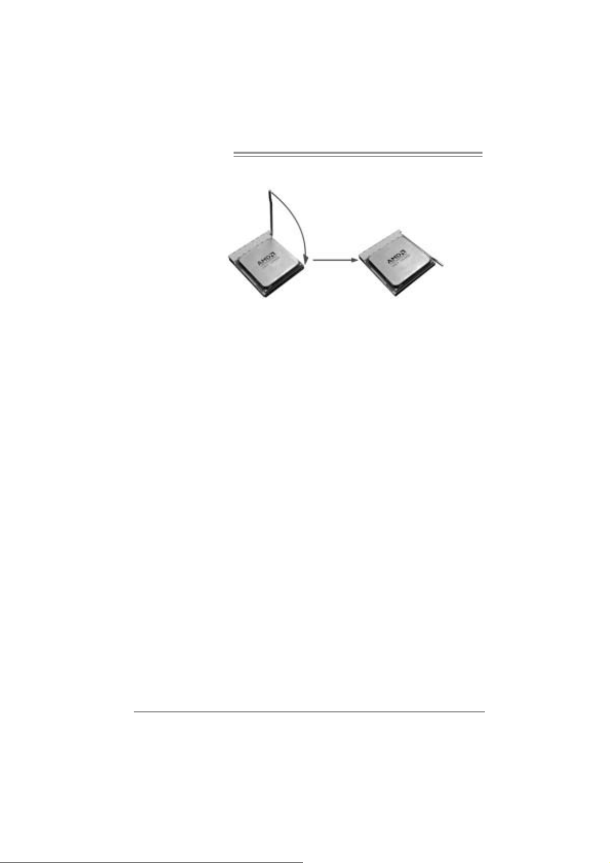
Step 4: Hold the CPU down firmly, and then close the l ever toward direct
B to complete the installation.
Step 5: Put th e CP U Fan on the CPU a nd bu c kl e it. Conn ect the CPU
FAN power cable to the JCFAN1. This completes the installation.
8
Page 9
GF7025-M2 T E/GF7050-M2 SE
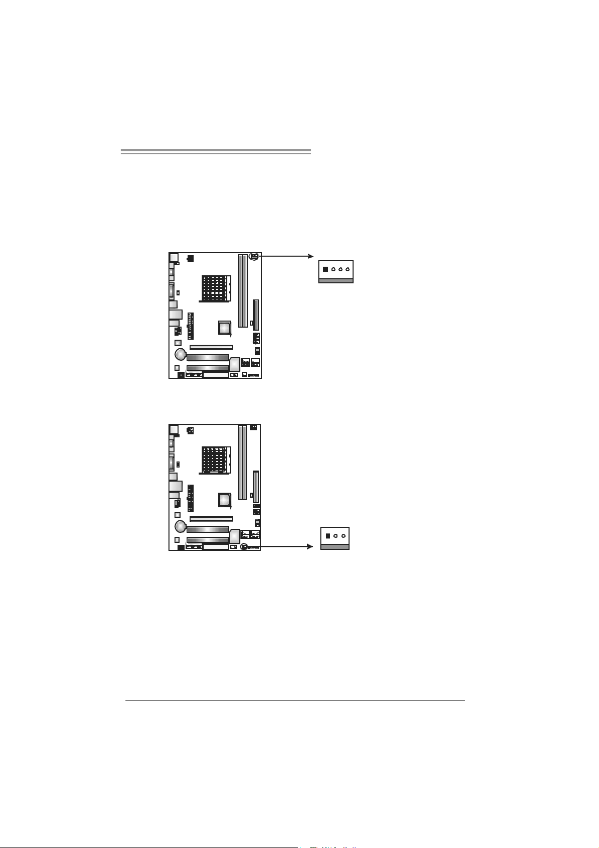
2.2 FAN HEADERS
These fan headers support cooling-fans built in the computer. The fan
cable and connector may be different according to the fan manufacturer.
Connect the fan cable to the connector while matching the black wire to
pin#1.
JCFAN1: CPU Fan Header
Pin
Assignment
1 Ground
2 +12V
3
FAN RPM rate
sense
4 Smart Fan
Control (By Fan)
Pin
Assignment
1 Ground
2 +12V
3 FAN RPM
rate sense
JSFAN1 : System Fan Head er
4
1
13
Note:
The JCFAN1 supports 4-pin head c onnector. The JSFAN1 supports 3-pin head
connector. When c onnecti ng with wires onto c onnectors, pl ease note that the red wire is
the positi ve and s hould be c onnected to pin#2, and the blac k wire is Ground and should
be connect ed to GND.
9
Page 10
Motherboard Manual
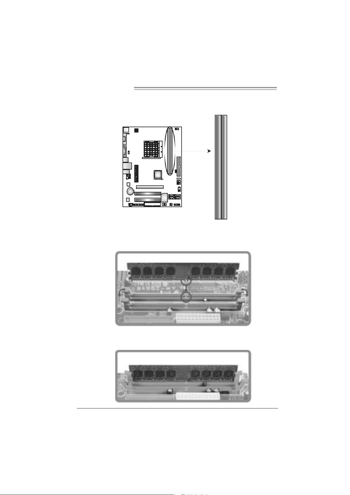
2.3 INSTALLING SYSTEM MEMORY
A. Me mo ry Module s
DIMMA1
DIMMB1
1. Unlock a DIMM sl ot by pressing the retaining clips outward. Ali gn a
DIMM on the slot such that the notch on the DIMM matches the
break on the Slot.
2. Insert the DIMM vertically and firmly into the slot until the retaining
chip snap back in place and the DIMM is properly seated.
10
Page 11
GF7025-M2 T E/GF7050-M2 SE
B. Memory Capacity
DI MM Socket
Location
DIMMA1 256MB/512MB/1GB/2GB
DIMMB1 256MB/512MB/1GB/2GB
DDR2 Module
To t al Mem o r y
Size
Max is 4 G B.
C. Dual Channel Me mory installation
To trigger t he Dual Channel func t ion of t he motherboard, the m emory m odule
must meet the following requirement s:
Install memory module of t he same density in pair, shown in t he following t able.
Du al Channel Statu s
Disabled O X
Disabled X O
Enabled O O
(O means memory installed, X m eans m emory not installed.)
The DRAM bus width of the memory module must be the same (x8 or
x16)
DIMMA1
DIMMB1
11
Page 12
Motherboard Manual
2.4 CONNECTORS AND SLOTS
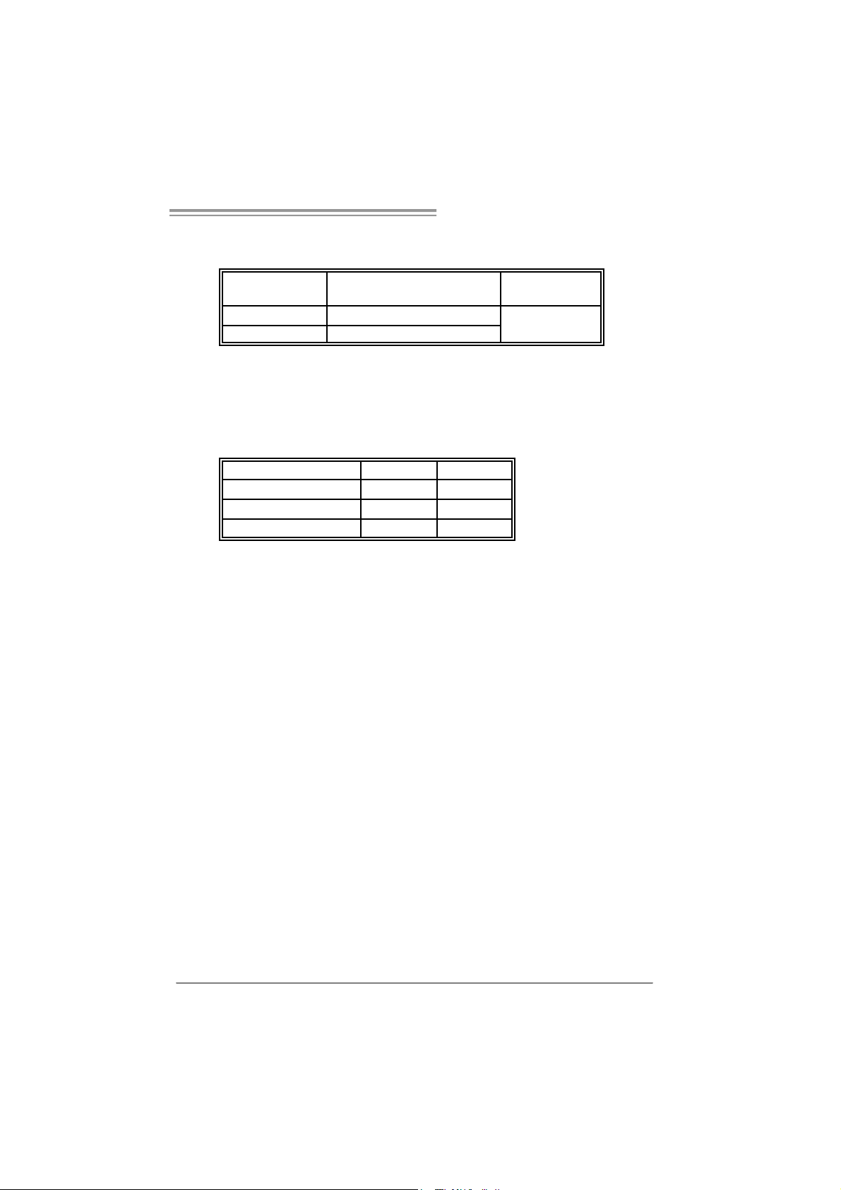
FDD1: Flo ppy Disk Connec to r
The motherboard provides a standard floppy disk connector that supports 360K,
720K, 1. 2M, 1.44M and 2. 88M f loppy disk types. This connector support s t he
provided f loppy driv e ribbon cables.
234
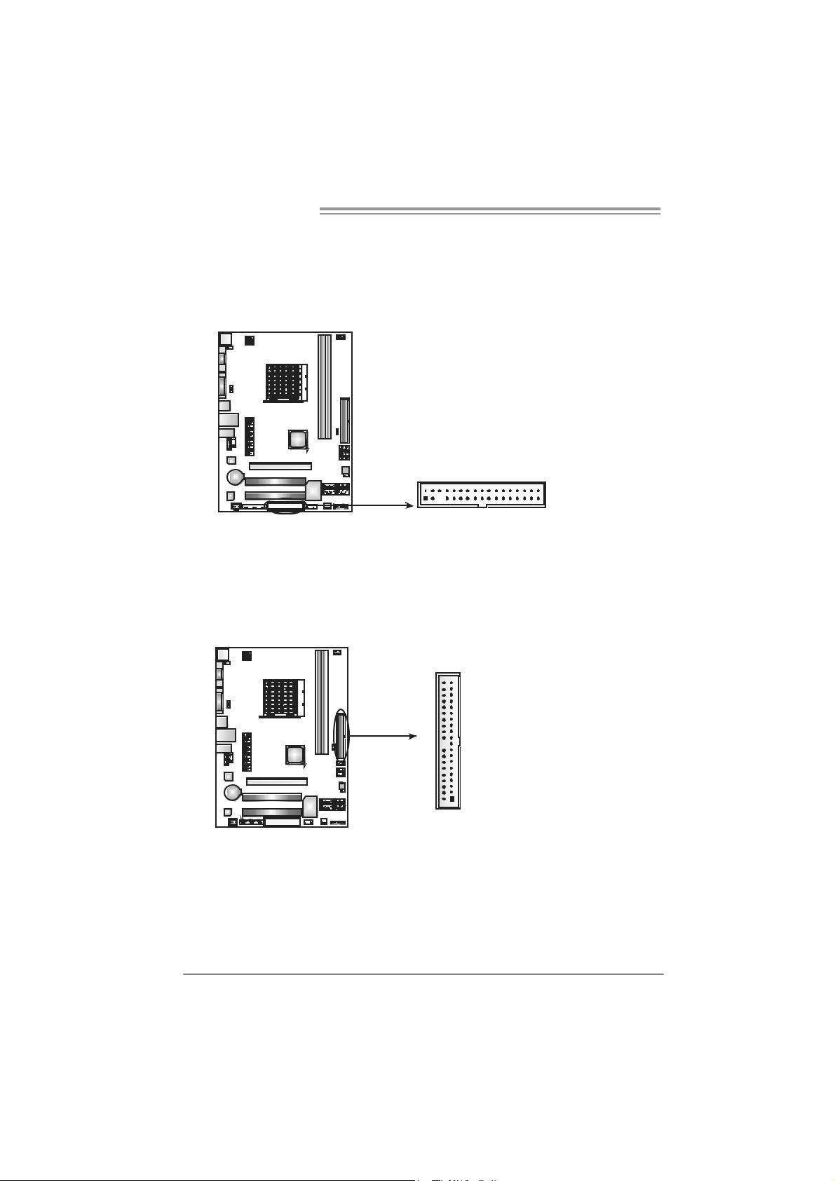
IDE1: H ar d Disk C onnec tor
The motherboard has a 32-bit Enhanced PCI IDE Cont roller that provides PIO
Mode 0~4, Bus Master, and Ult ra DMA 33/ 66/100/133 funct ionality.
The IDE connector can connect a m aster and a s lave drive, so y ou can connect
up to two hard disk drives.
133
3940
21
12
Page 13
GF7025-M2 T E/GF7050-M2 SE
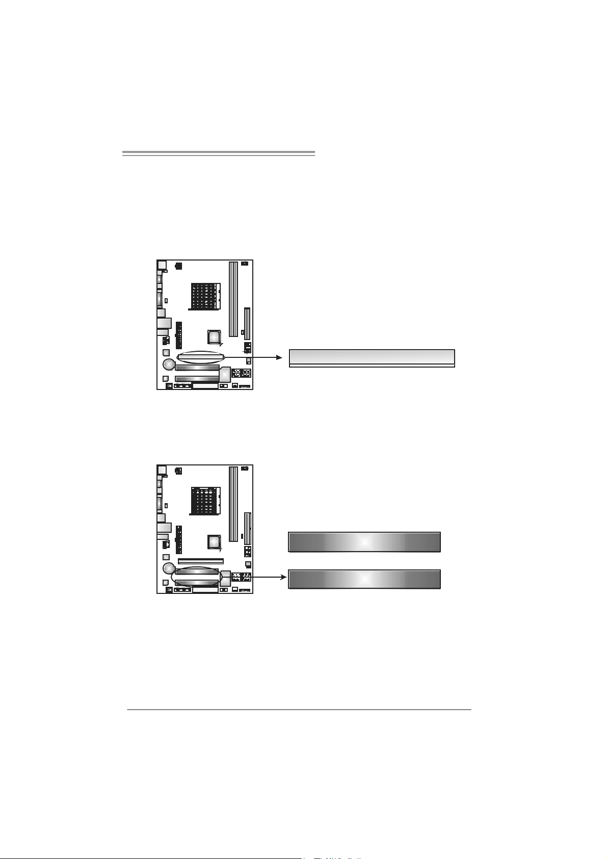
PCI-EX16: P CI- Expre s s x1 6 S lot
- PCI -Ex press 1.0a c ompliant.
- Maximum theoretical realized bandwidt h of 4GB/ s simultaneously per
direct ion, f or an aggregate of 8GB/s totally.
- PCI -Ex press supports a raw bit-rat e of 2. 5GB/s on the data pins.
- 2X bandwidth ov er the tradit ional PCI architecture.
PCI1~PCI2: Periphe ral Component Interconnect Sl ots
This mot herboard is equipped with 2 standard PCI slots. PCI stands f or
Peripheral Com ponent I nt erconnect, and it is a bus standard f or expansion
cards . This PCI slot is designated as 32 bits.
PCI-EX16
PCI1
PCI2
13
Page 14
Motherboard Manual
CHAPTER 3: HEADERS & JUMPERS SETUP
3.1 HOW TO SET UP JUMPERS
The illustration shows how to set up jumpers. When the jumper cap is
placed on pins, the j umper is “close”, if not, that means the jumper is
“open”.
Pin opened Pin closed Pin1-2 closed
3.2 DETAIL SETT INGS
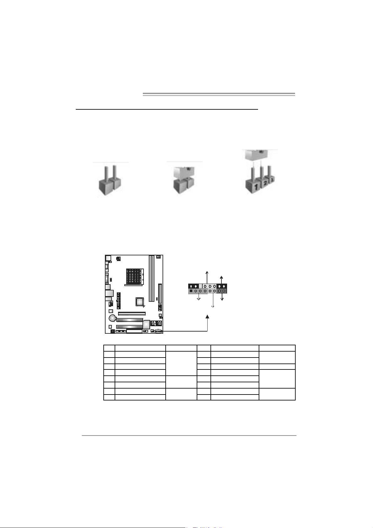
JPANEL1: Front Panel Header
This 16-pin connector includes Power-on, Reset, H DD LED, Power LED, and
speak er connection. It allows user to c onnect the PC cas e’s front panel s witc h
functions.
P WR_LED
On/Off
++
-
9
1
SPK
HLED
16
8
-
+
RST
14
Pin Assignment Functio n Pin Assignment Function
1 +5V 9 N/A
2 N/A 10 N/A
3 N/A 11 N/A N/A
4 Speaker
5 HDD LED (+) 13 Power LED (+)
6 HDD LED (-)
7 Ground 15 Power button
8 Reset control
Speaker
Connector
Hard drive
LED
Reset button
12 Power LED (+)
14 Power LED (-)
16 Ground
N/A
Powe r LED
Power-on button
Page 15

GF7025-M2 T E/GF7050-M2 SE
JATXPWR1: ATX Powe r Sou rce Co nne ctor
This connector allows user to connect 24-pin power connector on the ATX
power supply .
13
24
Pin Assignment Pin Assignment
13 +3.3V 1 +3.3V
14 -12V 2 +3.3V
15 Ground 3 Ground
16 PS_ON 4 +5V
17 Ground 5 Ground
18 Ground 6 +5V
19 Ground 7 Ground
20 NC 8 PW_OK
21 +5V 9 Standby Voltage+5V
22 +5V 10 +12V
23 +5V 11 +12V
24 Ground 12 +3.3V
1
12
JATXPWR4: ATX Powe r Sou rce Co nne ctor
By c onnecting this connector, it will provide +12V to CPU power circ uit.
1
2
4
3
Pin
Assignment
1 +12V
2 +12V
3 Ground
4 Ground
15
Page 16

Motherboard Manual
JUS B 2/ JUSB3/ JUSB4: H eader s for U SB 2. 0 P or t s at Fr o nt Pa ne l
This header allows us er to connect additional U SB cable on the PC front panel,
and also can be c onnected with internal U SB devices, like USB card reader.
Pin Assignment
JUSB3
JUSB2
JUSB4
10
129
S ATA1~SATA4: Serial ATA Connecto rs
The motherboard has a PCI to SATA C ontroller wit h 4 channels SATA interf ace.
SATA3
SATA1 SATA2
SATA4
1 +5V (fused)
2 +5V (fused)
3 USB4 USB-
5 USB+
6 USB+
7 Ground
8 Ground
9 Key
10 NC
Pin
Assignment
1 Ground
2 TX+
3 TX4 Ground
5 RX6 RX+
7 Ground
16
14 7
Page 17

GF7025-M2 T E/GF7050-M2 SE
JAUDIOF1: Fron t Panel Au dio Heade r
This header allows us er to connect the front audio out put cable with t he PC f ront
panel. This header allows only HD audio front panel connector; AC ’97 connector
is not accept able.
Pin Assignment
1 Mic Left i n
2 Ground
3 Mic Right in
10
2
9
1
4 GPIO
5 Right line in
6 Jack Sense
7 Front Sense
8 Key
9 Left line in
10 Jack Sense
JCDIN1: CD-ROM Aud io-in Connector
This connector allows user t o connect the audio s ourc e from the v ariaty devices,
like CD-R OM, DVD-ROM, PCI sound card, PCI TV turner card etc..
Assignment
Pin
1 Left Channel
1
4
Input
2 Ground
3 Ground
4 Right Channel
Input
17
Page 18

Motherboard Manual
JSPDI F_O UT1: Di gital Audio-out C on nec tor
This connector allows user to connect the PCI bracket SPDIF output header.
JCMOS 1 : C l ea r CMOS H e a der
By plac ing the jum per on pin2-3, it allows user to restore t he BIOS saf e set t ing
and the CMOS data, please carefully f ollow t he procedures to avoid damaging
the m otherboard.
※ Clear CMOS Procedures:
1. R em ove AC power line.
2. Set the jumper to “Pin 2-3 close”.
3. Wai t for fi ve se co n ds.
4. Set the jumper to “Pin 1-2 close”.
5. Power on the AC.
6. R es et your desired pass word or clear the C MOS dat a.
13
13
Pin
Assignment
1 +5V
2 SPDIF_OUT
3 Ground
13
Pin 1-2 Close:
Normal Operation
(default).
Pin 2-3 Close:
Clear CMOS data.
13
18
Page 19

GF7025-M2 T E/GF7050-M2 SE
JPRNT1: Printer Port Con nector
This header allows y ou to connector printer on t he PC.
2
125
Pin Assignment Pin Assignment
1 -Strobe 14 Ground
2 -ALF 15 Data 6
3 Data 0 16 Ground
4 -Error 17 Data 7
5 Data 1 18 Ground
6 -Init 19 -ACK
7 Data 2 20 Ground
8 -Scltin 21 Busy
9 Data 3 22 Ground
10 Ground 23 PE
11 Data 4 24 Ground
12 Ground 25 SCLT
13 Data 5 26 Key
JCOM1: Serial port Connector
The motherboard has a Serial Port Connector for c onnecting RS-232 Port.
Pin
Assignment
210
19
1 Carrier detect
2 Received data
3 Transmitted data
4 Data terminal ready
5 Signal ground
6 Data set ready
7 Request to send
8 Clear to send
9 Ring indicator
10 Key
19
Page 20

Motherboard Manual
JU SB P W R1/ JUSB P W R2: Powe r Sou rce Heade rs f or USB P orts
Pin 1-2 C lose:
JU SBPWR1: +5V f or USB port s at JUSB1/JU SBLAN1.
JU SBPWR2: +5V f or USB port s at front panel (JUSB2/JUSB3/JUSB4).
Pin 2-3 C lose:
JU SBPWR1: U SB ports at JUSB1/JUSBLAN1 are powered by +5V st andby
JU SBPWR2: USB ports at front panel (JU SB2/JUSB3/JUSB4) are powered
voltage.
by +5V standby voltage.
JUSBPWR1
3
1
3
1
Pin 1-2 close
3
1
JUSBPWR2
3
1
Pin 2-3 close
Note:
In order to support this function “Power-On s ystem via U SB device,” “JUSBPWR1/
JUSBPWR2” jumper c ap should be placed on Pi n 2-3 individually.
JKB MSPW R1: Power Source Heade r for PS /2 Ke yboard and Mouse
13
+5V for PS/2 keyboard and
mouse.
PS/2 keyboard and mouse are
powered by +5V standby
voltage.
13
Pin 1-2 close
13
Pin 2-3 close
Note:
In order to support this function “Power-on s ystem via keyboar d and mouse”,
“JKBMSPWR1” j umper cap should be placed on Pi n 2-3.
20
Page 21

GF7025-M2 T E/GF7050-M2 SE
CHAPTER 4: RAID FUNCTIONS
4.1 OPERATION SYSTEM
z Supports Windows XP H om e/Prof essional Edition, and Windows VISTA.
4.2 RAID ARRAYS
RAI D supports the f ollowing types of R AID array s :
RAID 0: RAID 0 defines a disk striping scheme that improves disk read and write times for
RAID 1: RAID 1 defines t echniques for mirroring data.
RAID 0+1: RAID 0+1 combines the techniques used in RAID 0 and RAID 1.
RAID 5: RAID 5 provides fault tolerance and better utilization of disk capacity.
many applications.
4.3 HOW RAID WORKS
RAID 0:
The controller “stripes” data across multiple drives in a RAID 0 array system. It breaks
up a large file into smaller blocks and performs disk reads and writes across multiple
drives in parallel. The size of each block i s determined by the stripe size parameter,
which you set during the creation of the RAID set based on the system environment. This
technique reduces o verall disk access time and offers hi gh bandwidth.
Fea tures and Be nefits
Drives: Minimum 1, and m ax imum is up to 6 or 8. Depending on t he
platform.
Uses: Intended for non-crit ical dat a requiring high dat a throughput, or any
environm ent that does not require f ault t oleranc e.
Benefits: prov ides inc reas ed dat a throughput, especially f or large files. No
capac ity loss penalty f or parity.
Drawbacks: Does not deliver any fault toleranc e. If any drive in the array
fails , all dat a is lost.
Fault To le rance : No.
Block 1
Bl ock 3
Bl ock 5
Block 2
Bl ock 4
Bl ock 6
21
Page 22

Motherboard Manual
RAID 1:
Every read and write is actually carried out in parallel across 2 disk drives in a RAID 1
array system. The mi rrored (b ackup) copy o f the data can reside on th e same d isk or o n a
second redundant drive in the array. RAID 1 provides a hot-standby copy of data if the
active volume o r drive is corrupt ed or beco mes unavailable because of a hardw are failure.
RAID techniques can be applied for high-availability solutions, or as a form of automatic
backup that eliminates tedious manual backups to more expensive and less reliable
me d i a .
Fea tures and Be nefits
Drives: Minimum 2, and m ax imum is 2.
Uses: RAID 1 is ideal f or sm all databases or any other applic at ion that
requires f ault tolerance and minimal capaci t y.
Benefits: Prov ides 100% data redundancy. Should one driv e f ail, t he
controller switches to the other dri ve.
Drawbacks: Requires 2 driv es for the s t orage spac e of one drive.
Perform anc e is impaired during driv e rebuilds.
Fault To le rance : Yes.
22
Block 1
Block 2
Block 3
Block 1
Block 2
Block 3
Page 23

GF7025-M2 T E/GF7050-M2 SE
RAID 0+1:
RAID 0 drives can be mirrored using RAID 1 techniques. Resulting in a RAID 0+1
solution for improved performance plus resiliency.
Fea tures and Be nefits
Drives: Minimum 4, and m ax imum is 6 or 8, depending on t he platf orm.
Benefits: Optimizes f or both fault tolerance and perf ormance, allowing f or
autom at ic redundancy. May be sim ultaneously used with other RAID lev els
in an array, and allows for s pare disks.
Drawbacks: Requires t wice the available disk spac e for data redundancy,
the same as RAID level 1.
Fault To le rance : Yes.
GeForce
7025/7050
NF630a
Block 1
Bl ock 3
Bl ock 5
Bl ock 2
Bl ock 4
Bl ock 6
Bl ock 1
Block 3
Block 5
Block 2
Block 4
Block 6
23
Page 24

Motherboard Manual
RAID 5:
RAID 5 stripes both data and parity information across three or more drives. It writes
data and parity blocks across all the drives in the array. Fault tolerance is maintained by
ensuring that the parity information for any given block of data is placed on a different
drive from those used to store the data itself.
Fea tures and Be nefits
Drives: Min i mum 3 .
Uses: RAID 5 is recommended for t rans action process ing and general
purpose s ervice.
Benefits: An ideal combination of good perf ormance, good fault tolerance,
and high capacity and st orage ef f ic iency.
Drawbacks: Individual bloc k data transfer rat e same as a single disk. W rit e
perform anc e can be CPU intensiv e.
Fault To le rance : Yes.
Disk 1
DATA 1
DATA 3
PARITY
DATA 7
DATA 9
PARITY
Disk 2
Ge F orce
70 25/ 7050
NF630a
DATA 2
PA R IT Y
DATA 5
DATA 8
PA R IT Y
DATA 11
Disk 3
PA R IT Y
DATA 4
DATA 6
PA R IT Y
DATA 1 0
DATA 1 2
※ For more detailed setup information, please refer to the Driver CD, or go to
http://www.nvidia.com/object/IO_28159.html to download the NVIDIA RAID User’s Guide.
24
Page 25

CHAPTER 5: USEFUL HELP
5.1 DRIVER INSTALLA TION NOTE
After you install ed your operating system, please insert the Fully Setup
Driver CD into your optical drive and install the dri ver for better system
performance.
You will see the following wi ndow after you insert the CD
GF7025-M2 T E/GF7050-M2 SE
The set up guide will auto detect yo ur motherboa rd and operati ng system.
Note:
If this window didn’t show up after you ins ert the Driver CD, please use file browser to
l ocate and e xecu te t h e fi l e SETU P.E XE un der yo ur o pti cal dr i ve .
A. Driver Installation
To install the dri ver, pl ease click on the Dri ver icon. The setup gui de will
list the compatible driver for your motherboard and operating system.
Click on each devi ce driver to launch the installati on program.
B. Software Installation
To install the software, please click on the Software icon. The setup guide
will list the software available for your system, click on each software title
to la unch th e ins tallation pr ogr am.
C. Manual
Aside from the paperback manual, we also provide manual in the Driver
CD. Click on the Manual i con to browse for available manual.
Note:
You will ne ed Acrob at Read er to op en the man ua l file. Ple ase downloa d the latest ve rs ion
of Acrobat Reader software from
http://www.adobe.com/products/a crobat/readst ep2.html
25
Page 26

Motherboard Manual
5.2 AWARD BIOS BEEP CODE
Beep Sound Meanin g
One long beep f ollowed by t wo s hort
beeps
High-low siren sound CPU overheated
One Short beep when system boot-up No error found during POST
Long beeps every ot her second No DRAM detected or ins t all
Video card not f ound or video card
mem ory bad
Sys t em will shut down automat ically
5.3 EXT RA INFORMATION
CPU Overheated
If the system shutdown automatically after power on system for
seconds, that means the CPU protecti on function has been activated.
When the CPU is over heated, the motherboard wi ll shutdown
automatically to avoid a damage of the CPU, and the system may not
power on again.
In this case, please double check:
1. The CPU cooler surface is pl aced evenly with the CPU surface.
2. CPU fan is rotated normally.
3. CPU fan speed is fulfilling with the CPU speed.
After confirmed, please follow steps below to relief the CPU protection
function.
1. Remove the power cord from power suppl y for seconds.
2. Wai t for seconds.
3. Plug i n the power cord and boot up the system.
Or you can:
1. Clear the CMOS data.
(See “Close CMOS Header: JCM OS1” section)
2. Wai t for seconds.
3. Pow er on the system again.
26
Page 27

5.4 TROUBLESHOOTING
e
Probable Solution
1. N o power to the sy stem at all
Power light don’t illuminat e, fan
inside power s upply does not turn
on.
2. I ndic at or light on k eyboard does
not t urn on.
Sys t em inoperat iv e. Keyboard lights
are on, power indic at or lights are lit,
and hard driv e is s pinning.
Sys t em does not boot from hard disk
drive, can be boot ed from optical drive.
Sys t em only boots from optical drive.
Hard disk can be read and applications
can be used but booting from hard dis k
is imposs ible.
Screen m essage say s “Invalid
Conf igurat ion” or “CMOS Failure.”
Cannot boot sys t em aft er inst alling
sec ond hard drive.
GF7025-M2 T E/GF7050-M2 SE
1. Make s ure power c able is
sec urely plugged in.
2. Replace cable.
3. Contact technical support.
Us ing even pres s ure on bot h ends of
the DIMM, press down f irm ly until t he
module s naps int o place.
1. C hec k cable running f r om disk to
disk controller board. Make sure
both ends are s ec urely plugged
i n; c heck t he d riv e type in th e
standard CMOS se tup.
2. Bac k ing up the hard drive is
ext rem ely import ant. All hard
disk s are c apable of breaking
down at any t ime.
1. Bac k up data and applicat ions
files.
2. R eformat t he hard drive.
Re-ins t all applicat ions and data
using backup disks.
Rev iew sys tem’s equipment . Make sur
correc t inf ormation is in setup.
1. Set m ast er/slave jum pers
correctly.
2. R un SETUP program and selec t
correc t driv e ty pes. Call the drive
manufacturers for co mpatibili t y
with other drives.
27
Page 28

Motherboard Manual
APPENDENCIES: SPEC IN OTHER LANG UAGE
GERMAN
GF7025- M2 T E G F70 50- M2 S E
Sockel AM2
AM D Athlon 64 / At hlon 64 FX / Athlon 64 x2 /
CPU
FSB
Chipsatz GeForce 7025/NF630a GeForce 7050/NF630a
Super E/A
Arbeitsspeich
er
Grafi k
IDE
SA TA II
LAN
Sempron Prozessoren
Die AMD 64-Architektur unterstützt eine 32-Bitund 64-Bit-Datenverarbeit ung
Unterstützt Hyper Transport und Cool’n’Quiet
Unterstützt HyperTrans port m it ei ner Bandbreite
von bis zu 1 GHz
ITE 8716F
Bi etet die häufig verwendeten alten Super
E/A-Funktionen.
Low Pin Count-Schnittstelle
Umgebungs kontrolle,
Hardware-Überwachung
Lüfterdrehz ahl-Controller
"Smart Guardian"-Funktion von ITE
DDR2 DIMM-Steckplätz e x 2
M a x. 4GB A r be itss p eic her
Jeder DIMM unterstützt 256MB/512MB /1GB /
2GB DDR 2.
Dual-Kanal DDR2 Speichermodul
Unt erstützt DDR2 533 / 667 / 800
registrierte DIMMs. ECC DIMMs werden nicht
unterstützt.
Int egrierter GeForce 7025/NF630a-Chi psatz
Max. 512MB gemeinsam benutzter
Videospeicher
Integrierter IDE-Controller
Ultra DMA 33 / 66 / 100 / 133 Bus
Master-Modus
Unterstützt PIO-Modus 0~4,
I nt e gri ert e r S e ri al ATA - Con tr o ll e r
Datentransferrate bis zu 3Gb/s
Konform mit der SATA-Spezifikation V ersion 2.0.
Realtek RTL 8201CL
10 / 100 Mb/s Auto-Negotiation
Halb-/ Vollduplex-Funktion
Sockel AM2
AM D Athlon 64 / At hlon 64 FX / Athlon 64 x2 /
Sempron Prozessoren
Die AMD 64-Architektur unterstützt eine 32-Bitund 64-Bit-Datenverarbeit ung
Unterstützt Hyper Transport und Cool’n’Quiet
Unterstützt HyperTrans port m it ei ner Bandbreite
von bis zu 1 GHz
ITE 8716F
Bi etet die häufig verwendeten alten Super
E/A-Funktionen.
Low Pin Count-Schnittstelle
Umgebungs kontrolle,
Hardware-Überwachung
Lüfterdrehz ahl-Controller
"Smart Guardian"-Funktion von ITE
DDR2 DIMM-Steckplätz e x 2
M a x. 4GB A r be itss p eic her
Jeder DIMM unterstützt 256MB/512MB /1GB /
2GB DDR 2.
Dual-Kanal DDR2 Speichermodul
Unt erstützt DDR2 533 / 667 / 800
registrierte DIMMs. ECC DIMMs werden nicht
unterstützt.
Int egrierter GeForce 7050/NF630a-Chi psatz
Max. 512MB gemeinsam benutzter
Videospeicher
Integrierter IDE-Controller
Ultra DMA 33 / 66 / 100 / 133 Bus
Master-Modus
Unterstützt PIO-Modus 0~4,
I nt e gri ert e r S e ri al ATA - Con tr o ll e r
Datentransferrate bis zu 3Gb/s
Konform mit der SATA-Spezifikation V ersion 2.0.
Realtek RTL 8201CL
10 / 100 Mb/s Auto-Negotiation
Halb-/ Vollduplex-Funktion
28
Page 29

GF7025-M2 T E/GF7050-M2 SE
GF7025- M2 T E G F70 50- M2 S E
Audio-Codec
Steckplätze
Onboard-Ans
chluss
Rückseiten-E
/A
Platinengröße
.
Sonderfunkti
onen
OS-Unt erstüt
zung
ALC662
5.1-Kanal-Audioausgabe
Unterstützt High-Definition Audio
PCI-Stec kplatz x2 PCI-Stec kplatz x2
PCI Express x16 Steckplatz x1 PCI Express x16 Steckplatz x1
Diskett enlaufwer kanschluss x1 Di sk ettenlaufwerkansc hluss x1
Druc ke ranschl uss A nschl uss x1 Druc ker anschl uss Ansc hl uss x1
IDE-A nschluss x1 IDE- A nschluss x1
SATA-Anschluss x4 SATA-Anschluss x4
Fronttafelanschluss x1 Fronttafelanschluss x1
Fr ont-Audi oansc hluss x1 Fr ont-Audi oansc hluss x1
CD-IN-Anschl uss x1 CD-IN-Anschl uss x1
S/PDIF- Ausgangsanschluss x1 S/PDIF- Aus gangsanschluss x1
CPU-Lüfter-Sockel x1 CPU-Lüfter-Sockel x1
System-Lüfter-Sockel x1 System-Lüfter-Sockel x1
"CMOS löschen"-Sockel x1 "C MOS löschen"-Sockel x1
US B-A nschluss x3 US B-A nschluss x3
Serieller A nsc hluss x1 Seriell er A nschluss x1
Stromanschluss (24-polig) x1 Stromanschluss (24-polig) x1
Stromanschluss (4-polig) x1 Stromanschluss (4-polig) x1
PS/2-Tastatur x1
PS/2-Maus x1
VGA-A nschl uss x1
DV I -D-A nschl uss x1
LAN-Ansc hl uss x1
US B-A nschluss x4
Audi o anschl uss x3
190 mm (B) X 244 mm (L) 190 m m (B) X 244 mm (L)
Unt erstützt RAID 0 / 1 / 5 / 0+ 1 Unterstützt RAID 0 / 1 / 5 / 0+ 1
Windows XP / VISTA
Biostar behält sich das Recht vor, ohne
Ankündigung die Unterstützung für ein
Betriebssystem hinzuz ufügen oder zu
entfernen.
ALC662
5.1-Kanal-Audioausgabe
Unterstützt High-Definition Audio
PS/2-Tastatur x1
PS/2-Maus x1
VGA-A nschl uss x1
DV I -D-A nschl uss x1
LAN-Ansc hl uss x1
US B-A nschluss x4
Audi o anschl uss x3
Windows XP / VISTA
Biostar behält sich das Recht vor, ohne
Ankündigung die Unterstützung für ein
Betriebssystem hinzuz ufügen oder zu
entfernen.
29
Page 30

Motherboard Manual
FRANCE
GF7025- M2 T E GF7050- M2 S E
Socket AM2
Pr ocess e urs AM D Athlon 64 / At hl on 64 FX /
UC
Bus frontal
Chipset GeForce 7025/NF630a GeForce 7050/NF630a
Super E/S
Mémoire
princ i pale
Graphiques
IDE
SA TA II
LAN
Athlon 64 x2 / Sempron
L'architectur e AMD 64 permet le calcul 32 et 64
bits
Prend en charge Hyper Transport et Cool’n’Quiet
Prend en charge Hyper Transport jusqu'à une
bande passante de1 GHz
ITE 8716F
Four nit la fonctionnalité de Super E/S
patrimoniales la plus utilisée.
Interface à faible compte de broches
Initiatives de contrôle environnement ales,
Moniteur de matéri el
Contrôleur de vitesse de vent ilateur
Fonction "Gardien intelligent" de l'ITE
Fentes DDR2 DIMM x 2
Capacité mémoire maximale de 4 Go
C ha qu e DI MM pre n d en c ha r ge d es DDR 2 de 25 6
Mo/512 Mo et 1Go/2Go
Modul e de mémoire DDR2 à mode à double voie
Prend en charge la DDR2 533 / 667 / 800
Les DIMM à registres et DIMM avec code
correcteurs d' erreurs ne sont pas prises en
charge
Int egré dans l a chipset GeFor ce 7025/NF630a
Mémoire vi déo partagée maximale de 512 Mo
Contrôleur I DE intégré
Mode principale de Bus Ultra DMA 33 / 66 / 100 /
133
Prend en charge le mode PIO 0~4,
Cont r ôl eur Se rial ATA intégré :
Taux de transfert jusqu'à 3 Go/s.
Conforme à la spécification SATA Version 2.0
Realtek RTL 8201CL
10 / 100 Mb/s négociation automati que
Half / Full duplex capability
Socket AM2
Pr ocess e urs AM D Athlon 64 / At hl on 64 FX /
Athlon 64 x2 / Sempron
L'architectur e AMD 64 permet le calcul 32 et 64
bits
Prend en charge Hyper Transport et Cool’n’Quiet
Prend en charge Hyper Transport jusqu'à une
bande passante de1 GHz
ITE 8716F
Four nit la fonctionnalité de Super E/S
patrimoniales la plus utilisée.
Interface à faible compte de broches
Initiatives de contrôle environnement ales,
Moniteur de matéri el
Contrôleur de vitesse de vent ilateur
Fonction "Gardien intelligent" de l'ITE
Fentes DDR2 DIMM x 2
Capacité mémoire maximale de 4 Go
C ha qu e DI MM pre n d en c ha r ge d es DDR 2 de 25 6
Mo/512 Mo et 1Go/2Go
Modul e de mémoire DDR2 à mode à double voie
Prend en charge la DDR2 533 / 667 / 800
Les DIMM à registres et DIMM avec code
correcteurs d' erreurs ne sont pas prises en
charge
Int egré dans l a chipset GeFor ce 7050/NF630a
Mémoire vi déo partagée maximale de 512 Mo
Contrôleur I DE intégré
Mode principale de Bus Ultra DMA 33 / 66 / 100 /
133
Prend en charge le mode PIO 0~4,
Cont r ôl eur Se rial ATA intégré :
Taux de transfert jusqu'à 3 Go/s.
Conforme à la spécification SATA Version 2.0
Realtek RTL 8201CL
10 / 100 Mb/s négociation automati que
Half / Full duplex capability
30
Page 31

GF7025-M2 T E/GF7050-M2 SE
GF7025- M2 T E GF7050- M2 S E
Codec audio
Fentes
Connecteur
embarqué
E/S du
panneau
arrière
Dim ensions
de la carte
Fonctionnali
tés
spéciales
Support SE
ALC662
Sortie audio à 5. 1 voies
Prise en charge de l'audio haute definition
Fente PCI x2 Fente PCI x2
Slot PCI Express x16 x1 Slot PCI Express x16 x1
Connecteur de disquette x1 C onnect eur de disquette x1
Connecteur de Port d'imprimante x1 Connecteur de Port d'imprimante x1
Connecteur IDE x1 C onnect eur IDE x1
Connec te ur SATA x4 C onnect eur SATA x4
Connecteur du panneau avant x1 Connect eur du panneau avant x1
Connecteur A udio du panneau avant x1 Connect eur Audio du panneau avant x1
Connecteur d'entrée CD x1 Connec teur d'entrée CD x1
Connecteur de sortie S/PDIF x1 Connecteur de sortie S/PDIF x1
Embase de ventilateur UC x1 Embase de ventilateur UC x1
Embase de ventilateur système x1 Embase de ventilateur système x1
Embase d'effacem ent CMOS x1 Embase d'effacement CMOS x1
Connecteur USB x3 Connecteur USB x3
Connecteur de Port série x1 Connecteur de Port série x1
Connecteur d'alimentation x1
(24 broc hes)
Connecteur d'alimentation x1
(4 broches)
Clavier PS/2 x1
Souris PS/2 x1
Port VGA x1
Port DVI-D x1
Port LAN x1
Port USB x4
Fiche audio x3
190 mm (l) X 244 mm (H) 190 mm (l) X 244 mm (H)
Prise en charge RAID 0 / 1 / 5 / 0+1 Pr ise en charge RAI D 0 / 1 / 5 / 0+1
Windows XP / VISTA
Biostar se réserve le droit d'ajouter ou de
supprimer le support de S E avec ou sans préavis.
ALC662
Sortie audio à 5. 1 voies
Prise en charge de l'audio haute definition
Connecteur d'alimentation x1
(24 broc hes)
Connecteur d'alimentation x1
(4 broches)
Clavier PS/2 x1
Souris PS/2 x1
Port VGA x1
Port DVI-D x1
Port LAN x1
Port USB x4
Fiche audio x3
Windows XP / VISTA
Biostar se réserve le droit d'ajouter ou de
supprimer le support de S E avec ou sans préavis.
31
Page 32

Motherboard Manual
ITALIAN
GF7025- M2 T E GF7050- M2 S E
Socket AM2
Processori AMD Athlon 64 / Athlon 64 FX /
CPU
FSB
Chipset GeForce 7025/NF630a GeForce 7050/NF630a
Super I/O
Memoria
principal e
Grafica
IDE
SATA II
LAN
Athlon 64 x2 / Sempron
L’architettura AMD 64 abilita la
computaz ione 32 e 64 bit
Suppor to di Hyper Tra nsport e Cool’ n’Quiet
Suppor to di Hyper Transp ort fi no a1 GHz di
larghez za di banda
ITE 871 6F
Fornisce le funzionalità legacy Super I/O
usate più comunemente.
Interfaccia LPC (Low Pin Count)
Funzioni di controllo dell’ambiente:
Monitoraggio hardware
Controller velocità ventolina
Funz ione "Sm ar t G uardi an" di I TE
Al loggi DI MM DDR 2 x 2
Capacità massima della memoria 4GB
Ci as cun DIMM s u pporta DDR 2 25 6MB/
512MB e 1GB/2 GB
Modulo di memoria DDR2 a c an ale dop pio
Supporto di DDR2 533 / 667 / 800
DIMM registrati e DIMM ECC non sono
support at i
Integrat a nel Chi pset GeForce
702 5/NF 63 0a
La memoria video condivisa massima è di
512MB
Controller IDE integrato
Modalità Bus Master Ultra DMA 33 / 66 /
100 / 133
Suppor to m odalit à PIO Mode 0- 4
Controller Serial ATA integrato
Velocità di trasferim ento dei dati fi no a 3
Gb/s .
Compatibile specifiche SATA Versione 2.0.
Realtek RTL 8201CL
Negoziazione autom at i c a 10 / 10 0 Mb /s
Capacità Half / Full Duplex
Socket AM2
Processori AMD Athlon 64 / Athlon 64 FX /
Athlon 64 x2 / Sempron
L’architettura AMD 64 abilita la
computaz ione 32 e 64 bit
Suppor to di Hyper Tra nsport e Cool’ n’Quiet
Suppor to di Hyper Transp ort fi no a1 GHz di
larghez za di banda
ITE 871 6F
Fornisce le funzionalità legacy Super I/O
usate più comunemente.
Interfaccia LPC (Low Pin Count)
Funzioni di controllo dell’ambiente:
Monitoraggio hardware
Controller velocità ventolina
Funz ione "Sm ar t G uardi an" di I TE
Al loggi DI MM DDR 2 x 2
Capacità massima della memoria 4GB
Ci as cun DIMM s u pporta DDR 2 25 6MB/
512MB e 1GB/2 GB
Modulo di memoria DDR2 a c an ale dop pio
Supporto di DDR2 533 / 667 / 800
DIMM registrati e DIMM ECC non sono
support at i
Integrat a nel Chi pset GeForce
705 0/NF 63 0a
La memoria video condivisa massima è di
512MB
Controller IDE integrato
Modalità Bus Master Ultra DMA 33 / 66 /
100 / 133
Suppor to m odalit à PIO Mode 0- 4
Controller Serial ATA integrato
Velocità di trasferim ento dei dati fi no a 3
Gb/s .
Compatibile specifiche SATA Versione 2.0.
Realtek RTL 8201CL
Negoziazione autom at i c a 10 / 10 0 Mb /s
Capacità Half / Full Duplex
32
Page 33

GF7025-M2 T E/GF7050-M2 SE
GF7025- M2 T E GF7050- M2 S E
Codec
audio
Alloggi
Connettori
su scheda
I/O
pannello
posteriore
Dim ens ion
i scheda
Caratterist
iche
speciali
Sistemi
operativi
support at i
ALC662
Uscita audio 5.1 ca nali
Supporto audio High-Definition (HD)
Alloggio PCI x2 Alloggio PCI x2
Al loggio PCI Ex press x1 6 x1 Alloggio PC I Express x1 6 x1
Connettore fl o ppy x1 Connettore flo ppy x1
Connettore Port a stampa nte x1 Connettore Port a stampa nte x1
Connettore I DE x1 Connet t ore IDE x1
Connettore S A TA x4 Connettore S A TA x4
Connettore pa nnello fro nt ale x1 C onnettore pa nnello fro nt al e x1
Connettore audio frontale x1 Connettore audio frontale x1
Connettore CD-in x1 Connettore CD-in x1
Connettore output SPDIF x1 Connettore output SPDIF x1
Collettore ventolina CPU x1 Collettore ventolina CPU x1
Collettore ventolina sistema x1 Collettore ventolina sistema x1
Collettore cancellazione CMOS x1 Collettore cancellazione CMOS x1
Connettore USB x3 C onnettore USB x3
Connettore Porta seriale x1 Connettore Porta seriale x1
Connettore alimentazione x1
(24 pin)
Connettore alimentazione x1
(4 pin)
Ta s t ie ra P S/ 2 x1
Mouse PS/2 x1
Porta VGA x1
Porta DVI-D x1
Porta LAN x1
Porta USB x4
Connettore au dio x3
19 0 mm (largh ez z a) x 24 4 mm (altez z a) 190 mm (largh ezza) x 244 mm (alt ezza)
Supporto R AID 0 / 1 / 5 / 0+1 Supporto R AID 0 / 1 / 5 / 0+1
Windows XP / VISTA
Biostar si riserva il diritto di aggiungere o
rimuovere il supporto di qualsiasi sistema
operativo s e nza pre avviso.
ALC662
Uscita audio 5.1 ca nali
Supporto audio High-Definition (HD)
Connettore alimentazione x1
(24 pin)
Connettore alimentazione x1
(4 pin)
Ta s t ie ra P S/ 2 x1
Mouse PS/2 x1
Porta VGA x1
Porta DVI-D x1
Porta LAN x1
Porta USB x4
Connettore au dio x3
Windows XP / VISTA
Biostar si riserva il diritto di aggiungere o
rimuovere il supporto di qualsiasi sistema
operativo s e nza pre avviso.
33
Page 34

Motherboard Manual
SPANISH
GF7025- M2 T E GF7050- M2 S E
CPU
FSB
Conjunto de
chips
Súper E/S
Memoria
princ i pal
Gráficos
IDE
SA TA II
Red Local
Conector AM2
Procesadores AMD Athlon 64 / Athlon 64 FX /
Athlon 64 x2 / Sempron
La arquitectura AMD 64 permite el procesado de
32 y 64 bits
Soporta las tecnologías Hyper Transport y
Cool’n’Quiet
Admite HyperTransport con un anc ho de banda
de hasta1 GHz
GeForce 7025/NF630a GeForce 7050/NF630a
ITE 8716F
Le ofrece las funcionalidades heredadas de uso
más común Súper E/S.
Interfaz de cuenta Low Pin
Iniciativas de control de entorno,
Monitor hardware
Controlador de velocidad de ventilador
Función "Guardia inteligente" de ITE
Ranuras DIMM DDR2 x 2
Capacidad máxima de memoria de 4GB
Cada DIMM admit e DDR de 256MB/512MB y
1GB/2GB
Módul o de memoria DDR 2 de canal Doble
Admite DDR2 de 533 / 667 / 800
No admite DIMM registrados o DIMM
compatibles con ECC
Int egrados en el conjunt o de chips GeForce
7025/NF630a
Memoria máxima de vídeo compartida de
512MB
Controlador IDE integrado
Modo bus maestr o Ultra DMA 33 / 66 / 100 / 133
Soporte los Modos PIO 0~4,
Controlador ATA Serie Integrado
Tasas de transferencia de hasta 3 Gb/s.
Compatible con la versión SATA 2. 0.
Realtek RTL 8201CL
Negociación de 10 / 100 Mb/s
Funciones Hal f / Full dúplex
Conector AM2
Procesadores AMD Athlon 64 / Athlon 64 FX /
Athlon 64 x2 / Sempron
La arquitectura AMD 64 permite el procesado de
32 y 64 bits
Soporta las tecnologías Hyper Transport y
Cool’n’Quiet
Admite HyperTransport con un anc ho de banda
de hasta1 GHz
ITE 8716F
Le ofrece las funcionalidades heredadas de uso
más común Súper E/S.
Interfaz de cuenta Low Pin
Iniciativas de control de entorno,
Monitor hardware
Controlador de velocidad de ventilador
Función "Guardia inteligente" de ITE
Ranuras DIMM DDR2 x 2
Capacidad máxima de memoria de 4GB
Cada DIMM admit e DDR de 256MB/512MB y
1GB/2GB
Módul o de memoria DDR 2 de canal Doble
Admite DDR2 de 533 / 667 / 800
No admite DIMM registrados o DIMM
compatibles con ECC
Int egrados en el conjunt o de chips GeForce
7050/NF630a
Memoria máxima de vídeo compartida de
512MB
Controlador IDE integrado
Modo bus maestr o Ultra DMA 33 / 66 / 100 / 133
Soporte los Modos PIO 0~4,
Controlador ATA Serie Integrado
Tasas de transferencia de hasta 3 Gb/s.
Compatible con la versión SATA 2. 0.
Realtek RTL 8201CL
Negociación de 10 / 100 Mb/s
Funciones Hal f / Full dúplex
34
Page 35

GF7025-M2 T E/GF7050-M2 SE
GF7025- M2 T E GF7050- M2 S E
Códecs de
sonido
Ranuras
Conectores
en plac a
Panel
trasero de
E/S
Ta m añ o de
la placa
ALC662
Salida de soni do de 5.1 canales
Soporte de sonido Alta Definición
Ranura PCI X2 R anura PCI X2
Ranura PCI Express x16 X1 Ranura PCI Expr ess x16 X1
Conector disco flexible X1 Conector disco flexible X1
C o nec t or Pu er t o de im p r es or a X 1 C on ec t or Pu ert o de im pr es or a X 1
Conector IDE X1 Conector IDE X1
Conec t or SATA X4 C o nector SATA X 4
Conect or de panel front al X1 Conector de panel frontal X1
Conector de sonido frontal X1 Conector de sonido frontal X1
Conector de entrada de CD X1 Conector de entrada de CD X1
Conector de salida S/PDIF X1 Conector de salida S/PDIF X1
Cabecera de ventilador de CPU X1 Cabecera de vent ilador de CPU X1
Cabecera de ventilador de sistema X1 Cabecera de vent ilador de sistema X1
Cabecera de borrado de CMOS X1 Cabecera de borrado de CMOS X1
Conector USB X3 Conector USB X3
Conector Puerto serie X1 Conector Puerto serie X1
Conector de alimentación X1
(24 pat illas)
Conector de alimentación X1
(4 patillas)
Te c l ado PS / 2 X1
Ratón PS/2 X1
Puerto VGA X1
Puerto DVI-D X1
Puerto de red loc al X 1
Puerto USB X4
Conector de sonido X3
190 mm. (A) X 244 M m. (H) 190 mm. (A) X 244 M m. (H)
ALC662
Salida de soni do de 5.1 canales
Soporte de sonido Alta Definición
Conector de alimentación X1
(24 pat illas)
Conector de alimentación X1
(4 patillas)
Te c l ado PS / 2 X1
Ratón PS/2 X1
Puerto VGA X1
Puerto DVI-D X1
Puerto de red loc al X 1
Puerto USB X4
Conector de sonido X3
Funciones
especiales
Soporte de
sistema
operativo
Admite RAID 0 / 1 / 5 / 0+1 Admite RAI D 0 / 1 / 5 / 0+1
Windows XP / VISTA
Biostar se reserva el derecho de añadir o retirar
el soporte de cualquier SO con o sin aviso previo.
Windows XP / VISTA
Biostar se reserva el derecho de añadir o retirar
el soporte de cualquier SO con o sin aviso previo.
35
Page 36

Motherboard Manual
PORTUGUESE
GF7025- M2 T E GF7050- M2 S E
Socket AM2
Processadores AMD Athlon 64 / Athlon 64 FX /
Athlon 64 x2 / Sempron
CPU
FSB
Chipset GeForce 7025/NF630a GeForce 7050/NF630a
Es pecificaçã
o Super I/O
Memória
princ ipal
Placa
gráfica
IDE
SA TA II
LAN
A ar quit ect ura AMD 64 perm ite uma comput aç ão
de 32 e 64 bits
Suporta as tecnologias Hyper Transport e
Cool’n’Quiet
Suporta a tec nologia HyperTransport com uma
largura de banda at é1 GHz
ITE 8716F
Proporciona as funcionalidades mais utilizadas
em termos da especificação Super I/O.
Int erface LPC (Low Pin Count).
Iniciativas para controlo do ambiente
Monitorização do hardw are
Controlador da velocidade da ventoinha
Função "Smart Guardian" da ITE
Ranhuras DIMM DDR2 x 2
Capacidade máxima de memória: 4 GB
Cada módulo DIMM suporta uma memória
DDR2 de 256 MB/512 MB & 1 GB/2 GB
Módulo de memória DDR2 de canal duplo
Suporta módul os DDR2 533 / 667 / 800
Os módulos DIMM registados e os DIMM ECC
não são suportados
Int egrada no chi pset GeForce 7025/NF630a
Memória de vídeo máxima partilhada: 512 MB
Controlador IDE integrado
Modo Bus m ast er Ultra DMA 33 / 66 / 100 / 133
Suporta o modo PIO 0~4,
Controlador Serial ATA i nt egrado
Velocidades de transmissão de dados até 3 Gb/s.
Compatibilidade com a especificação SATA
v e rs ã o 2. 0.
Realtek RTL 8201CL
Auto negociação de 10 / 100 Mb/s
Capacidade semi/full-duplex
Socket AM2
Processadores AMD Athlon 64 / Athlon 64 FX /
Athlon 64 x2 / Sempron
A ar quit ect ura AMD 64 perm ite uma comput aç ão
de 32 e 64 bits
Suporta as tecnologias Hyper Transport e
Cool’n’Quiet
Suporta a tec nologia HyperTransport com uma
largura de banda at é1 GHz
ITE 8716F
Proporciona as funcionalidades mais utilizadas
em termos da especificação Super I/O.
Int erface LPC (Low Pin Count).
Iniciativas para controlo do ambiente
Monitorização do hardw are
Controlador da velocidade da ventoinha
Função "Smart Guardian" da ITE
Ranhuras DIMM DDR2 x 2
Capacidade máxima de memória: 4 GB
Cada módulo DIMM suporta uma memória
DDR2 de 256 MB/512 MB & 1 GB/2 GB
Módulo de memória DDR2 de canal duplo
Suporta módul os DDR2 533 / 667 / 800
Os módulos DIMM registados e os DIMM ECC
não são suportados
Int egrada no chi pset GeForce 7050/NF630a
Memória de vídeo máxima partilhada: 512 MB
Controlador IDE integrado
Modo Bus m ast er Ultra DMA 33 / 66 / 100 / 133
Suporta o modo PIO 0~4,
Controlador Serial ATA i nt egrado
Velocidades de transmissão de dados até 3 Gb/s.
Compatibilidade com a especificação SATA
v e rs ã o 2. 0.
Realtek RTL 8201CL
Auto negociação de 10 / 100 Mb/s
Capacidade semi/full-duplex
36
Page 37

GF7025-M2 T E/GF7050-M2 SE
GF7025- M2 T E GF7050- M2 S E
Codec de
som
Ranhuras
Conectores
na placa
Entradas/S
aídas no
painel
traseiro
Tamanho
da placa
Característi
cas
especiais
Sistemas
operativos
suportados
ALC662
Saída de áudio de 5. 1 canais
Suporta a especificação High-Definit ion Audio
Ranhura PCI x2 R anhura PCI x2
Ranhura PCI Express x16 x1 Ranhura PCI Express x16 x1
Conect or da unidade de disquetes x1 Conect or da unidade de di s quetes x1
Conector da para impressora x1 Conector da para impressora x1
Conector IDE x1 Conector IDE x1
Conec t or SATA x4 C onec t or SATA x4
Conect or do painel frontal x1 Conect or do painel frontal x1
Conector de áudio front al x1 Conect or de áudio fr ontal x1
Conector para entrada de CDs x1 Conect or para entrada de CDs x1
Conector de saída S/PDIF x1 Conector de saída S/PDIF x1
Conector da ventoinha da CPU x1 C onector da ventoinha da CPU x1
Conector da ventoinha do sistema x1 C onect or da ventoinha do sistema x1
Conector para limpeza do CMOS x1 Conector para limpeza do CMOS x1
Conector USB x3 Conector USB x3
Conector da Porta série x1 Conector da Porta série x1
Conector de alimentação x1
(24 pinos)
Conector de alimentação x1
(4 pinos)
Te c l ado PS / 2 x1
Rato PS/2 x1
Porta VGA x1
Porta DVI-D x1
Porta LAN x1
Porta USB x4
Tomada de áudio x3
190 mm (L) X 244 mm (A) 190 mm (L) X 244 mm (A)
Suporta as funções RAID 0 / 1 / 5 / 0+1 Suporta as funções RAID 0 / 1 / 5 / 0+1
Windows XP / VISTA
A Biostar reserva-se o direito de adicionar ou
remover suporte para qualquer sistema
operativo com ou s em aviso prévio.
ALC662
Saída de áudio de 5. 1 canais
Suporta a especificação High-Definit ion Audio
Conector de alimentação x1
(24 pinos)
Conector de alimentação x1
(4 pinos)
Te c l ado PS / 2 x1
Rato PS/2 x1
Porta VGA x1
Porta DVI-D x1
Porta LAN x1
Porta USB x4
Tomada de áudio x3
Windows XP / VISTA
A Biostar reserva-se o direito de adicionar ou
remover suporte para qualquer sistema
operativo com ou s em aviso prévio.
37
Page 38

Motherboard Manual
POLISH
GF7025- M2 T E GF7050- M2 S E
Socket AM2
AM D Athlon 64 / At hlon 64 FX / Athlon 64 x2 /
Procesor
FSB
Chipset GeForce 7025/NF630a GeForce 7050/NF630a
Pamięć
główna
Super I/O
Grafika
IDE
SA TA II
LAN
38
Sem pron Procesory
Architektura AMD 64 um ożliwi a przetwarzanie
32 i 64 bi t owe
Obsługa Hyper Transport oraz Cool’n’Q uiet
Obsługa HyperTransport o szerokości pasma do1
GHz
Gniaz da DDR2 DIMM x 2
Maks. wielkość pa mi ęci 4GB
Każde gniazdo DIMM obsługuje moduły
256MB /512M B oraz 1GB/2GB DDR 2
Moduł pamięci DDR2 z trybem podwójnego
kanału
Obsługa DDR 2 533 / 667 / 800
Brak obsługi Registered DIMM oraz ECC DIMM
ITE 8716F
Zapewnia najbardziej powszechne funkcje Super
I/O.
Int erfejs Low Pin Count
Funkcje kontroli warunków pracy,
Monitor H/W
Kontroler prędkości w ent ylatora
Funkcja ITE "Smart Guardian"
Zintegrowana w c hipsecie GeForce
7025/NF630a
Maks. wielkość ws pó łdzielonej pamięci video
wynosi 512MB
Z i nt e g ro w an y k o nt rol er I DE
Ultra DMA 33 / 66 / 100 / 133 Tryb Bus Master
obsłu ga P I O t r y b 0~ 4,
Zint egrowany kontroler Serial ATA
Transfer danych do 3 Gb/s.
Zgodność ze specyfikacją SATA w wersji 2.0.
Realtek RTL 8201CL
10 / 100 Mb/s z automatyczną negocjac ją
szybkości
Działanie w trybie połow icz ne g o / pełnego
dupleksu
Socket AM2
AM D Athlon 64 / At hlon 64 FX / Athlon 64 x2 /
Sem pron Procesory
Architektura AMD 64 um ożliwi a przetwarzanie
32 i 64 bi t owe
Obsługa Hyper Transport oraz Cool’n’Q uiet
Obsługa HyperTransport o szerokości pasma do1
GHz
Gniaz da DDR2 DIMM x 2
Maks. wielkość pa mi ęci 4GB
Każde gniazdo DIMM obsługuje moduły
256MB /512M B oraz 1GB/2GB DDR 2
Moduł pamięci DDR2 z trybem podwójnego
kanału
Obsługa DDR 2 533 / 667 / 800
Brak obsługi Registered DIMM oraz ECC DIMM
ITE 8716F
Zapewnia najbardziej powszechne funkcje Super
I/O.
Int erfejs Low Pin Count
Funkcje kontroli warunków pracy,
Monitor H/W
Kontroler prędkości w ent ylatora
Funkcja ITE "Smart Guardian"
Zintegrowana w c hipsecie GeForce
7050/NF630a
Maks. wielkość ws pó łdzielonej pamięci video
wynosi 512MB
Z i nt e g ro w an y k o nt rol er I DE
Ultra DMA 33 / 66 / 100 / 133 Tryb Bus Master
obsłu ga P I O t r y b 0~ 4,
Zint egrowany kontroler Serial ATA
Transfer danych do 3 Gb/s.
Zgodność ze specyfikacją SATA w wersji 2.0.
Realtek RTL 8201CL
10 / 100 Mb/s z automatyczną negocjac ją
szybkości
Działanie w trybie połow icz ne g o / pełnego
dupleksu
Page 39

GF7025-M2 T E/GF7050-M2 SE
GF7025- M2 T E GF7050- M2 S E
Kodek
dźwięko wy
Gniazda
Złącz a
wbudowane
Back Panel
I/O
Wymiary
płyty
Funkcje
specjalne
ALC662
5.1 kanałow e w y jście audio
Obsługa High-Definition Audio
Gniazdo PCI x2 Gniazdo PCI x2
Gniazdo PCI Express x16 x1 Gniazdo PCI Express x16 x1
Złącz e napędu dyskietek x1 Złącz e napędu dyskietek x1
Złącze Port drukarki x1 Złącze Port drukarki x1
Złącz e IDE x1 Złącze IDE x1
Złącz e SA TA x 4 Z łącz e SATA x 4
Złącz e panela przedniego x1 Złącze panela przedniego x1
Przednie złą cz e audio x1 Przedni e złącz e audio x1
Złącz e w ejścia C D x1 Złącze w ejścia C D x1
Złącz e w yjści a S /P DIF x 1 Z łącz e wy jścia S /PD IF x1
Złącz e głów kow e w ent yl ato r a
proces ora x1
Złącz e głów kow e w ent yl ato r a
systemowego x1
Złącz e głów ko we k as ow ani a
CMOS x1
Złącz e USB x3 Z łącz e USB x3
Złącz e Port sz eregowy x 1 Z łącz e Port sz eregowy x 1
Złącz e z asilani a (24 pi now e) x1 Złącze zas ila nia ( 24 pinowe) x1
Złącz e z asilani a (4 pi nowe ) x1 Z łącz e z asilani a (4 pi now e) x1
Klawiatura PS/2 x1
Mysz PS/2 x1
Port VGA x1
Port DVI-D x1
Port LAN x1
Port USB x4
Gniazdo audio x3
190 mm (S) X 244 mm (W) 190 mm (S) X 244 mm (W)
Obsługa RAID 0 / 1 / 5 / 0+1 O bsługa RAID 0 / 1 / 5 / 0+1
ALC662
5.1 kanałow e w y jście audio
Obsługa High-Definition Audio
Złącz e głów kow e w ent yl ato r a
proces ora x1
Złącz e głów kow e w ent yl ato r a
systemowego x1
Złącz e głów ko we k as ow ani a
CMOS x1
Klawiatura PS/2 x1
Mysz PS/2 x1
Port VGA x1
Port DVI-D x1
Port LAN x1
Port USB x4
Gniazdo audio x3
Obsluga
systemu
operacyjne
go
Windows XP / VISTA
Bi ostar zastrze ga s obie prawo dodawania lub
odwoływania obsługi dowolnego systemu
o p er ac y j n ego be z po w i ad om i eni a.
Windows XP / VISTA
Bi ostar zastrze ga s obie prawo dodawania lub
odwoływania obsługi dowolnego systemu
o p er ac y j n ego be z po w i ad om i eni a.
39
Page 40

Motherboard Manual
р
Б
RUSSIAN
G F70 25- M2 TE GF7050- M2 S E
Гнездо AM 2
Процессоры AM D At hl on 64 / At hlon 64 FX /
Athlon 64 X2 / Sempron
Архитектура AMD 64 разрешать обработка
данны х на 32 и 64 бит
Поддержка Hyper Transport и Cool’n’Quiet
Поддержка HyperTransport с пропускной
способностью до1GГц
Слоты DDR2 DIMM x 2
Максимальная ём к ос т ь пам яти 4 ГБ
Каждый модуль DIMM подде
/512МБ & 1ГБ/2ГБ DDR2
Модуль пам яти с двухканальным режимом
DDR2
Поддержка DDR2 533 / 667 / 800
Не поддерж ивает зарегистрированные
модули DIMM and ECC DIMM
ITE 8716F
Обеспечивает наиболее ис п о ль зу е м ы е
действующие функциональные
возможности Super I/O.
Интерфейс с низ ким количес твом вы в о дов
Иниц иативы по охране окруж ающей среды,
Аппаратный монитор
Регулятор скорости
Функция ITE "Smart Guardian"
(Интеллектуальная защита)
Вс троенная в набор микросхем GeF orce
7050/NF630a
Максимальная совместно ис п о ль зу е м ая
видео память составляет 512 МБ
Вс троенное ус тр о й с тво управления
встроенны ми интерфе йсами устройств
Режим "хозяина" шины Ultra DM A 33 / 66 /
100 / 133
Поддержка режима PIO 0~4,
Вс троенное пос ледовательное устройство
управления ATA
скорость передачи данны х до 3 гигабит/с.
Соответствие с пециф икац ии SA TA версия
2.0.
CPU
(центральный
проц ессор)
FSB
Набор
микросхем
Основная
память
Super I/O
Графика
IDE
SA TA II
Гнездо AM 2
Процессоры AM D At hl on 64 / At hlon 64 FX /
Athlon 64 X2 / Sempron
Архитектура AMD 64 разрешать обработка
данны х на 32 и 64 бит
Поддержка Hyper Transport и Cool’n’Quiet
Поддержка HyperTransport с пропускной
способностью до1GГц
GeForce 7025/NF630a GeForce 7050/NF630a
Слоты DDR2 DIMM x 2
Максимальная ём к ос т ь пам яти 4 ГБ
Каждый модуль DIMM поддерживает 256 МБ
/512МБ & 1ГБ/2ГБ DDR2
Модуль пам яти с двухканальным режимом
DDR2
Поддержка DDR2 533 / 667 / 800
Не поддерж ивает зарегистрированные
модули DIMM and ECC DIMM
ITE 8716F
Обеспечивает наиболее ис п о ль зу е м ы е
действующие функциональные
возможности Super I/O.
Интерфейс с низ ким количес твом вы в о дов
Иниц иативы по охране окруж ающей среды,
Аппаратный монитор
Регулятор скорости
Функция ITE "Smart Guardian"
(Интеллектуальная защита)
Вс троенная в набор микросхем GeF orce
7025/NF630a
Максимальная совместно ис п о ль зу е м ая
видео память составляет 512 МБ
Вс троенное ус тр о й с тво управления
встроенны ми интерфе йсами устройств
Режим "хозяина" шины Ultra DM A 33 / 66 /
100 / 133
Поддержка режима PIO 0~4,
Вс троенное пос ледовательное устройство
управления ATA
скорость передачи данны х до 3 гигабит/с.
Соответствие с пециф икац ии SA TA версия
2.0.
живает 256 М
40
Page 41

GF7025-M2 T E/GF7050-M2 SE
/
/
G F70 25- M2 TE GF7050- M2 S E
Локальная
сеть
Звуковой
кодек
Слоты
Вс троенны й
разъём
Задняя
панель
средств
ввода-вы во д а
Размер
панели
Специальные
технические
характеристи
ки
Поддержка
OS
Realtek RTL 8201CL
Автоматическ ое согласование 10
Частичная / полная дуплексная способность
ALC662
5.1канальны й звуковой выход
Звуковая поддерж ка High-Definition
Слот PCI x2 Слот PCI x2
Слот PCI Express x16 x1 Слот PCI Express x16 x1
Разъём НГМД x1 Разъём НГМД x1
Разъём Порт подключения
принтера x1
Разъём IDE x1 Раз ъём IDE x1
Разъём SATA x 4 Раз ъём SATA x4
Разъём на лиц евой панели x1 Разъём на лиц евой панели x1
Входной звуковой разъём x1 Входной звуковой раз ъём x1
Разъём ввода для CD x1 Раз ъём ввода для CD x1
Разъём вы во д а для S/PDIF x1 Разъём вы в о да для S/PDIF x1
Контактирующее прис пособление x1
вентилятора центрального проц есс ора
Контактирующее прис пособление
вентилятора системы x1
Открытое ко н т а ктир ую щ е е
приспос обление CMO S x1
USB-раз ъём x3 USB-раз ъём x3
Разъём Последовательны й порт x1 Раз ъём Последовательный порт x1
Разъем питания (24 вы в о д ) x 1 Разъем питания (24 вы в о д) x 1
Разъем питания (4 вы в о д) x 1 Раз ъем питания (4 вы в о д) x 1
Клавиатура PS/2 x1
Мышь PS / 2 x1
Порт VGA x1
Порт DVI-D x1
Порт LAN x1
USB-порт x4
Гнездо для подключения наушников x3
190 мм (Ш) X 244 мм (В) 190 мм (Ш) X 244 мм (В)
Поддержка RAID 0 / 1 / 5 / 0+ 1 Поддержка RAI D 0 / 1 / 5 / 0+1
Windows XP / VISTA
Biostar сохраняет за собой право добавлять
или удалять средства обеспечения для OS с
или без предваритель ного уведомления.
100 Мб/с
Realtek RTL 8201CL
Автоматическ ое согласование 10
Частичная / полная дуплексная способность
ALC662
5.1канальны й звуковой выход
Звуковая поддерж ка High-Definition
Разъём Порт подключения
принтера x1
Контактирующее прис пособление x1
вентилятора центрального процессора
Контактирующее прис пособление
вентилятора системы x1
Открытое ко н т а ктир ую щ е е
приспос обление CMO S x1
Клавиатура PS/2 x1
Мышь PS / 2 x1
Порт VGA x1
Порт DVI-D x1
Порт LAN x1
USB-порт x4
Гнездо для подключения наушников x3
Windows XP / VISTA
Biostar сохраняет за собой право добавлять
или удалять средства обеспечения для OS с
или без предваритель ного уведомления.
100 Мб/с
41
Page 42

Motherboard Manual
/
/
/
ARABIC
تﺎ ﺠﻟﺎ ﻌﻡ AMD Athlon 64
ﺔ ﻴﻨﻘ ﺗ ﻦﻜﻤﺗ AM D 64 ﺏ ﺔﻴﺏﻮﺳﺎ ﺤﻟا تﺎﻴﻠﻤﻌﻟا ءاﺮﺝ إ ﺔﻋﺮﺴ32 و64 ﺖﺏ
ﺔ ﻴﻨﻘﺗ ﻢﻋ ﺪ ﺗ Hyper Transport و Cool’n’Quiet
ﺔ ﻴﻨﻘﺗ ﻢﻋ ﺪ ﺗ HyperTransport ﻰﻟإ ﻞﺼﻳ ددﺮﺘ ﺏ 1000دد ﺮ ﺗ
ﺔﺤﺘﻓ ﻞآ ﻢﻋ ﺪ ﺗ DIMM عﻮ ﻥ ﻦﻡ ةﺮآ اذ ﻢﻋ ﺪﺗ DDR2 ﺔﻌﺳ
عﻮﻥ ﻦﻡ ةﺮ آ اﺬﻟا ﻢﻋ ﺪ ﺗ DDR2 تﺎﻌﺳ 533 / 667 / 800ﺖﻳﺎ ﺏ ﺎﺠﻴﻡ
ةﺮآ اﺬﻟا ﻖﺋﺎﻗر ﻢﻋ ﺪﺗ ﻻDIM M ﻟا ﻚﻠﺗ و ﻊﻡ ﻖﻓاﻮﺘ ﺗ ﻻ ﻲﺘ ECC
ﺔﻔﻴﻇو ﺮﻓﻮﺗSuper I/O ﺮﺜ آ ﻷا ًﺎﻡاﺪ ﺨ ﺘ ﺳ ا .
ﺗﻢﻋ ﺪ ﺔ ﻴﻨﻘﺗ
ﺔﻔﻴﻇو"Smart Guardian" ﻦﻡ ITE
ﻲﻓ ﺔﺠﻡﺪﻡ ﻖﺋ ﺎ ﻗر GeForce 7050/NF630a
ﺔآﺮﺘﺸﻤﻟا ﻮﻳﺪﻴﻔﻟا ةﺮآاﺬﻟ ﺔﻌﺳ ﻰﺼ ﻗ أ512ﺖﻳﺎ ﺏ ﺎﺠﻴﻡ
ﺔ ﻴﻨﻘﺘ ﺏ ﻞﻗﺎﻥUltra DMA 33 / 66 / 100 / 133ﻲﺴﻴﺋ ر ﻊﺿ و
تﺎﻔﺹاﻮﻤﻟ ﺔﻘﺏﺎﻄﻡSA TA راﺪﺹﻹا 2. 0.
Athlon 64 FX /
Athlon 64 x2
ةﺮآ اذ ةﺪﺣوDDR2 ﻘﻟا ﺔﺝودﺰﻡةﺎﻨ
Low Pin Count Interface
ﺔ ﺌﻴﺒ ﻟا ﻲﻓ ﻢﻜ ﺤﺘ ﻟا ﻞﺋ ﺎﺳو:
ةﺰﻬ ﺝﻷ ا ﺔﻟﺎﺣ ﺔﻓﺮﻌﻤﻟ ﺐﻗاﺮﻡ
ﺔﺣوﺮﻤﻟا ﺔﻋﺮﺳ ﻲﻓ ﺐﻗاﺮﻡ
ﻊﺿو ﻢﻋدPIO Mode 0~4
ﻢﻜﺤﺘﻡSerial ATAﻞﻡﺎﻜﺘﻡ
ﻰﻟإ ﻞﺼﺗ تﺎﻋﺮﺴﺏ ت ﺎﻥ ﺎﻴﺒﻟا ﻞﻘﻥ3 ﺖﺏﺎﺠﻴﺝ/ﺔ ﻴﻥﺎﺙ.
Realtek RTL 8201CL
ﻞﻡﺎﻜﻟا جودﺰﻤ ﻟا ﻞﻘﻨﻟا ﺔﻴﻥ ﺎﻜﻡ إ/ﻲﻔﺼ ﻨﻟا
ﺲﺒﻘﻡAM2
Sempron
ﺔﺤ ﺘ ﻓDDR2 DIMM دﺪﻋ2
ىﻮﺼﻗ ةﺮآاذ ﺔﻌﺳ4 ﺖﻳ ﺎﺏ ﺎﺠﻴ ﺝ
256/512 ﺎﺠﻴﻡ
و ﺖﻳﺎﺏ1/2 ﺎﺠﻴﺝﺖﻳﺎ ﺏ
ITE 8716F
ﻢﻜﺤﺘﻡIDEﻞﻡﺎﻜﺘﻡ
ﻲﺋﺎﻘﻠﺗ ضوﺎ ﻔﺗ10/100 ﺖﻳ ﺎﺏ ﺎﺠﻴ ﻡ /ﺔﻴﻥﺎﺙ
تﺎ ﺠﻟﺎ ﻌﻡ AMD Athlon 64 / Athl on 64 FX
Athlon 64 x2 / Sempron
ﺔ ﻴﻨﻘ ﺗ ﻦﻜﻤﺗ AM D 64 ﺔﻋﺮﺴﺏ ﺔﻴﺏﻮﺳﺎﺤﻟا تﺎﻴﻠﻤﻌﻟا ءاﺮﺝ إ 32 و64 ﺖﺏ
ﺔ ﻴﻨﻘﺗ ﻢﻋ ﺪ ﺗ Hyper Transport و Cool’n’Quiet
ﺔﺤﺘﻓ ﻞآ ﻢﻋ ﺪ ﺗ DIMM عﻮ ﻥ ﻦﻡ ةﺮآ اذ ﻢﻋ ﺪﺗ DDR2 ﺔﻌﺳ
ةﺮآ اذ ةﺪﺣوDDR2 ﻘﻟا ﺔﺝودﺰﻡةﺎﻨ
عﻮﻥ ﻦﻡ ةﺮ آ اﺬﻟا ﻢﻋ ﺪ ﺗ DDR2 تﺎﻌﺳ 533 / 667 / 800ﺖﻳﺎ ﺏ ﺎﺠﻴﻡ
ةﺮآ اﺬﻟا ﻖﺋﺎﻗر ﻢﻋ ﺪﺗ ﻻDIM M اﻮ ﺘ ﺗ ﻻ ﻲﺘﻟا ﻚﻠﺗ و ﻊﻡ ﻖﻓ ECC
ﺔﻔﻴﻇو ﺮﻓﻮﺗSuper I/O ًﺎﻡ ا ﺪ ﺨ ﺘﺳا ﺮﺜ آ ﻷا .
ﺗﻢﻋ ﺪ ﺔ ﻴﻨﻘﺗ Low Pin Count Interface
ﺔ ﺌﻴﺒ ﻟا ﻲﻓ ﻢﻜ ﺤﺘ ﻟا ﻞﺋ ﺎﺳو:
ةﺰﻬ ﺝﻷ ا ﺔﻟﺎﺣ ﺔﻓﺮﻌﻤﻟ ﺐﻗاﺮﻡ
ﺔﺣوﺮﻤﻟا ﺔﻋﺮﺳ ﻲﻓ ﺐﻗاﺮﻡ
ﺔ ﻴﻨﻘﺘ ﺏ ﻞﻗﺎﻥUltra DMA 33 / 66 / 100 / 133ﻲﺴﻴﺋ ر ﻊﺿ و
ﺔﻔﻴﻇو"Smart Guardian" ﻦﻡ ITE
ﻖﺋ ﺎ ﻗر ﻲﻓ ﺔﺠﻡﺪﻡ GeForce 7025/NF630a
ﺔآﺮﺘﺸﻤﻟا ﻮﻳﺪﻴﻔﻟا ةﺮآاﺬﻟ ﺔﻌﺳ ﻰﺼ ﻗ أ512ﺖﻳﺎ ﺏ ﺎﺠﻴﻡ
ﻢﻜﺤﺘﻡIDEﻞﻡﺎﻜﺘﻡ
ﻊﺿو ﻢﻋدPIO Mode 0~4
ﻢﻜﺤﺘﻡSerial ATAﻞﻡﺎﻜﺘﻡ
ﻰﻟإ ﻞﺼﺗ تﺎﻋﺮﺴﺏ ت ﺎﻥ ﺎﻴﺒﻟا ﻞﻘﻥ3 ﺖﺏﺎﺠﻴﺝ/ﺔ ﻴﻥﺎﺙ.
تﺎﻔﺹاﻮﻤﻟ ﺔﻘﺏﺎﻄﻡSA TA راﺪﺹﻹا 2. 0.
Realtek RTL 8201CL
ﻞﻡﺎﻜﻟا جودﺰﻤ ﻟا ﻞﻘﻨﻟا ﺔﻴﻥ ﺎﻜﻡ إ/ﻲﻔﺼ ﻨﻟا
ﺲﺒﻘﻡAM2
ﺔﺤ ﺘ ﻓDDR2 DIMM دﺪﻋ2
ىﻮﺼﻗ ةﺮآاذ ﺔﻌﺳ4 ﺖﻳ ﺎﺏ ﺎﺠﻴ ﺝ
256/512 ﺎﺠﻴﻡ
و ﺖﻳﺎﺏ1/2 ﺎﺠﻴﺝﺖﻳﺎ ﺏ
ITE 8716F
ﻲﺒ ﻥ ﺎﺠ ﻟا ﻲﻡ ﺎﻡ ﻷا ﻞﻗﺎﻨﻟا ﺔ ﻴﻨﻘﺗ ﻢﻋ ﺪ ﺗ HyperTransport ﻰﻟإ ﻞﺼﻳ ددﺮﺘ ﺏ 1000دد ﺮ ﺗ
ﻔﺗ ﻲﺋﺎﻘﻠﺗ ضوﺎ10/100 ﺖﻳ ﺎﺏ ﺎﺠﻴ ﻡ /ﺔﻴﻥﺎ ﺙ
GF7025- M2 T E GF7050- M2 S E
ﺔ ﺠﻟﺎ ﻌﻤ ﻟا ةﺪﺣو
ﺔﻳﺰآﺮﻤ ﻟا
ﺢﺋ اﺮﺸﻟا ﺔﻋﻮﻤﺠﻡ GeForce 7025/NF630a GeForce 7050/NF630a
ﺔﻴﺴ ﻴﺋﺮﻟا ةﺮ آ اﺬ ﻟا
Super I/O
تﺎﻡﻮ ﺳﺮﻟا ﺔﻗﺎ ﻄﺏ
ﺬﻔ ﻨﻡIDE
SATA II
ﺔﻴﻠﺥ اد ﺔﻜﺒﺵ
42
Page 43

ﺔ ﻴﻨﻘﺗ ﻢﻋ ﺪ ﺗ RAID 0 / 1 / 5 / 0+1
ﻆﻔ ﺘﺤﺗ Biostar مﺎﻈﻥ يﻷ ﻢﻋ ﺪﻟ ا ﺔﻟازإ وأ ﺔﻓﺎﺿإ ﻲﻓ ﺎﻬﻘﺤﺏ وأ رﺎ ﻄﺥ ﺈ ﺏ ﻞﻴﻐﺸﺗ
ALC662
5.1 اﻮ ﻨ ﻗت جﺮﺨﻟ تﻮﺼ ﻟا
ﻦﻡ ﻒﻳﺮﻌﺘﻟا ﻲﻟﺎﻋ تﻮﺼ ﻟا ﺔ ﻴﻨﻘﺗ ﻢﻋ ﺪ ﺗ
ﺢﻴﺗﺎﻔﻡ ﺔﺣ ﻮ ﻟPS/2 دﺪﻋ1
سوﺎﻡ PS/2 دﺪﻋ1
ﺬﻓ ﺎﻨﻡVGA دﺪﻋ1
ﺬﻓ ﺎﻨﻡDVI-D دﺪﻋ1
ﺔﻴﻠ ﺤﻡ لﺎ ﺼ ﺗا ﺔﻜ ﺒ ﺵ ﺬﻔﻨﻡ دﺪﻋ1
ﺬﻓﺎﻨ ﻡUSB دﺪﻋ4
تﻮﺹ ﺲﺒﻘﻡ دﺪﻋ3
Windows XP / VISTA
رﺎ ﻄﺥ إ نوﺪﺏ.
GF7025-M2 T E/GF7050-M2 SE
ALC662
5.1 تاﻮﻨﻗ جﺮﺨﻟ تﻮﺼ ﻟا
ﻦﻡ ﻒﻳﺮﻌﺘﻟا ﻲﻟﺎﻋ تﻮﺼ ﻟا ﺔ ﻴﻨﻘﺗ ﻢﻋ ﺪ ﺗ
ﺔﺤ ﺘ ﻓPCI دﺪﻋ2 ﺔﺤ ﺘ ﻓPCI دﺪﻋ2
ﺔﺤ ﺘ ﻓx16 PCI Express دﺪﻋ1 ﺔﺤ ﺘﻓx16 PCI Express دﺪﻋ1
ﺔﻥﺮ ﻡ صاﺮﻗأ كﺮﺤﻡ ﺬﻔﻨﻡ دﺪﻋ1 ﺔﻥﺮ ﻡ صاﺮﻗأ كﺮﺤﻡ ﺬﻔﻨﻡ دﺪﻋ1
ﺔﻌﺏ ﺎﻃ ﺬﻔﻨﻡ دﺪﻋ1 ﺔﻌﺏ ﺎﻃ ﺬﻔﻨﻡ دﺪﻋ1
ﺬﻔﻨﻡIDE دﺪﻋ1 ﺬﻔﻨﻡIDE دﺪﻋ1
ﺬﻔﻨﻡSATA دﺪﻋ4 ﺬﻔﻨﻡSATA دﺪﻋ4
ﺔﻴ ﻡﺎ ﻡﻷا ﺔﺣﻮﻠﻟا ﺬﻔﻨﻡ دﺪﻋ1 ﺔﻴ ﻡﺎ ﻡﻷ ا ﺔﺣﻮﻠﻟا ﺬﻔﻨﻡ دﺪﻋ1
ﻲﻡﺎﻡﻷا تﻮﺼﻟا ﺬﻔﻨﻡ دﺪﻋ1 ﻲﻡﺎﻡﻷا تﻮﺼﻟا ﺬﻔﻨﻡ دﺪﻋ1
ﺬﻔﻨﻡCD-IN دﺪﻋ1 ﺬﻔﻨﻡCD-IN دﺪﻋ1
جﺮﺥ ﺬﻔﻨﻡS/PDI F دﺪﻋ1 جﺮﺥ ﺬﻔﻨﻡS/PDI F دﺪﻋ1
ﺔﻳﺰآ ﺮ ﻤﻟ ا ﺔﺠﻟﺎﻌﻤﻟا ةﺪ ﺣو ﺔﺣوﺮ ﻡ ﺔﻠﺹو دﺪﻋ1 ﺔﻳﺰآ ﺮ ﻤﻟ ا ﺔﺠﻟﺎﻌﻤﻟا ةﺪ ﺣو ﺔﺣوﺮ ﻡ ﺔﻠﺹو دﺪﻋ1
مﺎﻈﻨﻟا ﺔﺣوﺮ ﻡ ﺔﻠﺹو دﺪﻋ1 مﺎﻈﻨﻟا ﺔﺣوﺮ ﻡ ﺔﻠﺹو دﺪﻋ1
ﺢﺴﻡ ﺔﻠﺹوCMOS دﺪﻋ1 ﺢﺴﻡ ﺔﻠﺹوCMOS دﺪﻋ1
ﺬﻔﻨﻡUSB دﺪﻋ3 ﺬﻔﻨﻡUSB دﺪﻋ3
ﻲﻠﺴﻠﺴﺗ ﺬﻔﻨﻡ دﺪﻋ1 ﻲﻠﺴﻠﺴﺗ ﺬﻔﻨﻡ دﺪﻋ1
ﻞﻴﺹﻮﺗ ﺬﻔﻨﻡ ﺔﻗﺎﻄﻟا)24سﻮﺏد( دﺪﻋ1 ﺔﻗﺎﻄﻟا ﻞﻴﺹﻮﺗ ﺬﻔﻨﻡ)24سﻮﺏد( دﺪﻋ1
ﺔﻗﺎﻄﻟا ﻞﻴﺹﻮﺗ ﺬﻔﻨﻡ)4ﺲ ﻴﺏﺎ ﺏد( دﺪﻋ1 ﺔﻗﺎﻄﻟا ﻞﻴﺹﻮﺗ ﺬﻔﻨﻡ)4ﺲ ﻴﺏﺎ ﺏد( دﺪﻋ1
ﺢﻴﺗﺎﻔﻡ ﺔﺣ ﻮ ﻟPS/2 دﺪﻋ1
سوﺎﻡ PS/2 دﺪﻋ1
ﺬﻓ ﺎﻨﻡVGA دﺪﻋ1
ﺬﻓ ﺎﻨﻡDVI-D دﺪﻋ1
ﺔﻴﻠ ﺤﻡ لﺎ ﺼ ﺗا ﺔﻜ ﺒ ﺵ ﺬﻔﻨﻡ ﻋ دﺪ1
ﺬﻓﺎﻨ ﻡUSB دﺪﻋ4
تﻮﺹ ﺲﺒﻘﻡ دﺪﻋ3
Windows XP / VISTA
ﻆﻔ ﺘﺤﺗ Biostar وأ رﺎ ﻄﺥ ﺈ ﺏ ﻞﻴﻐﺸ ﺗ مﺎﻈﻥ يﻷ ﻢﻋ ﺪﻟ ا ﺔﻟازإ وأ ﺔﻓﺎﺿإ ﻲﻓ ﺎﻬﻘﺤﺏ
رﺎ ﻄﺥ إ نوﺪﺏ.
GF7025- M2 T E GF7050- M2 S E
تﻮﺼ ﻟا ﻚﻳ دﻮ آ
تﺎ ﺤﺘﻔ ﻟا
ﺢﻄﺳ ﻰﻠﻋ ﺬﻓﺎﻨﻤﻟا
ﺔﺣﻮﻠﻟا
ﻞﺥد ﺬﻓ ﺎﻨﻡ/ جﺮﺥ
ﺔﻴﻔﻠﺨﻟا ﺔ ﺣﻮﻠﻟا
ﺔﺹﺎﺥ ﺎﻳاﺰﻡ ﺔ ﻴﻨﻘﺗ ﻢﻋ ﺪ ﺗ RAID 0 / 1 / 5 / 0+1
ﻮﻠﻟا ﻢﺠ ﺣﺔﺣ 190 ﻢﻡ)ضﺮﻋ (X 244 ﻢﻡ)عﺎ ﻔ ﺗر ا( 190 ﻢﻡ)ضﺮﻋ (X 244 ﻢﻡ)عﺎ ﻔ ﺗر ا(
ﻞﻴﻐﺸﺘﻟا ﺔﻤﻈﻥأ ﻢﻋ د
43
Page 44

Motherboard Manual
JAPANESE
G F7025- M2 T E G F7050- M2 S E
Socket AM2
AM D Athlon 64 / At hlon 64 FX / Athlon 64 x2/
Sempron プロセッ サ
CPU
FSB
チッ プセット GeForce 7025/NF630a GeForce 7050/NF630a
メイ ンメモリ
Super I/O
グラ フィックス GeForce 7025/NF630aチ ップセット に統合
IDE
SA TA II
LAN
44
AMD 64アーキテクチャでは、 32ビットと 64ビット計
算が 可能です
ハイ パートラン スポートと クールアン ドクワイア ット
をサ ポートしま す
1GHzの バンド幅ま でハイパー トランスポ ートをサポ
ート します
DDR2 DIMMス ロット x 2
最大 メモリ容量 4GB
各DIMMは 256MB/512MB & 1GB/2GB DDR2をサ
ポー ト
デュ アル チャンネ ルモード DDR2メモリモ ジュール
DDR2 533 / 667 / 800をサポ ート
登録 済み DI M M とECC DIMMは サポートさ れません
ITE 8716F
もっ とも一般に 使用される レガシー Super I/O機能を
採用 しています 。
低ピ ンカウント インターフ ェイス
環境 コントロー ルイニシア チブ、
H/Wモニター
ファ ン速度コン トローラ / モニター
ITEの「スマー トガーディ アン」機能
最大 の共有ビデ オメモリは 512MBです
統合 IDEコン トローラ
Ultra DMA 33 / 66 / 100 / 133バス マスタモー ド
PIO Mode 0~ 4の サポート、
統合 シリアルATAコン トローラ
最高 3 Gb/秒のデータ転 送速度
SA TAバ ージョン 2. 0 仕様に準拠 。
Realtek RTL 8201CL
10 / 100 Mb/秒のオート ネゴシエー ション
半/全二 重機能
Socket AM2
AM D Athlon 64 / At hlon 64 FX / Athlon 64 x2/
Sempron プロセッ サ
AMD 64アーキテクチャでは、 32ビットと 64ビット計
算が 可能です
ハイ パートラン スポートと クールアン ドクワイア ット
をサ ポートしま す
1GHzの バンド幅ま でハイパー トランスポ ートをサポ
ート します
DDR2 DIMMス ロット x 2
最大 メモリ容量 4GB
各DIMMは 256MB/512MB & 1GB/2GB DDR2をサ
ポー ト
デュ アル チャンネ ルモード DDR2メモリモ ジュール
DDR2 533 / 667 / 800をサポ ート
登録 済み DI M M とECC DIMMは サポートさ れません
ITE 8716F
もっ とも一般に 使用される レガシー Super I/O機能を
採用 しています 。
低ピ ンカウント インターフ ェイス
環境 コントロー ルイニシア チブ、
H/Wモニター
ファ ン速度コン トローラ / モニター
ITEの「スマー トガーディ アン」機能
GeForce 7050/NF630aチ ップセット に統合
最大 の共有ビデ オメモリは 512MBです
統合 IDEコン トローラ
Ultra DMA 33 / 66 / 100 / 133バス マスタモー ド
PIO Mode 0~ 4の サポート、
統合 シリアルATAコン トローラ
最高 3 Gb/秒のデータ転 送速度
SA TAバ ージョン 2. 0 仕様に準拠 。
Realtek RTL 8201CL
10 / 100 Mb/秒のオート ネゴシエー ション
半/全二 重機能
Page 45

GF7025-M2 T E/GF7050-M2 SE
G F7025- M2 T E G F7050- M2 S E
サウ ンド
Codec
スロ ット
オン ボードコ
ネク タ
背面 パネル
I/O
ボー ドサイズ 190 mm (幅) X 244 mm (高さ) 190 mm (幅) X 244 mm (高さ)
特殊 機能 RAID 0 / 1 / 5 / 0+ 1 のサポート R AID 0 / 1 / 5 / 0+ 1 のサポート
OSサポート
ALC662
5.1チ ャンネルオ ーディオア ウト
ハイ デフィニシ ョンオーデ ィオのサポ ート
PCIスロット x2 PCIスロッ ト x2
PCI Express x16スロット x1 PCI Express x16スロット x1
フロ ッピーコネ クタ x1 フロッピーコネ クタ x1
プリ ンタポート コネクタ x1 プリ ンタポート コネクタ x1
IDEコネクタ x1 IDEコネクタ x1
SA TAコ ネクタ x4 SATAコネクタ x4
フロ ントパネル コネクタ x1 フロ ントパネル コネクタ x1
フロ ントオーデ ィオコネク タ x1 フロ ントオーデ ィオコネク タ x1
CDインコネクタ x1 CDインコネク タ x1
S/PDIFア ウトコネク タ x1 S/PDIFアウトコネク タ x1
CPUファ ンヘッダ x1 CPUファ ンヘッダ x1
シス テムファン ヘッダ x1 シス テムファン ヘッダ x1
CMOSクリアヘッ ダ x1 CMOSクリアヘッ ダ x1
USBコネクタ x3 USBコネクタ x3
シリ アルポート コネクタ x1 シリ アルポート コネクタ x1
電源 コネクタ (24ピン ) x1 電源 コネクタ (24ピン ) x1
電源 コネクタ (4ピン ) x1 電源 コネクタ (4ピン ) x1
PS/2キー ボード x1
PS/2マウ ス x1
VGAポート x1
DVI -Dポート x1
LANポート x1
USBポート x4
オー ディオジャ ック x3
Windows XP / VISTA
Biostarは事前 のサポート なしにOS サポートを 追加ま
たは 削除する権 利を留保し ます。
ALC662
5.1チ ャンネルオ ーディオア ウト
ハイ デフィニシ ョンオーデ ィオのサポ ート
PS/2キー ボード x1
PS/2マウ ス x1
VGAポート x1
DVI -Dポート x1
LANポート x1
USBポート x4
オー ディオジャ ック x3
Windows XP / VISTA
Biostarは事前 のサポート なしにOS サポートを 追加ま
たは 削除する権 利を留保し ます。
2007/11/16
45
 Loading...