

Page 1

G965 Micro 775 Setup Manual
FCC Inf or m at ion and Copyright
This equipment has been teste d and found to comply with the limits of
a Clas s B d ig ita l de vice, pursua n t to P a rt 15 of the FCC Rule s. The se
limits are designed to provide reasonable protection against harmful
inte rfe rence in a reside n tia l i nsta lla tio n. This equ ipment gene ra tes ,
uses and can rad iate radio frequency ene rg y and, if no t installed and
u sed in acco rdan ce with the in s tructions, ma y cau se ha rm fu l
in te rfe ren ce to ra d io communica tio ns. The re is no gua ran te e tha t
interference will not occur in a particular installation.
The vendor makes no representations or wa rran ties with respe ct to the
co n ten ts he re and spe cia lly d is cla ims a ny im plied warranties o f
me rcha ntability o r fitness for any purpose. Furthe r the vendor rese rves
the rig h t to re vi se thi s pub l ica t ion a n d to make changes to the con ten ts
here without obligation to no tify a ny party beforehand.
Dup lication of this pub l ica tion, in pa rt or in who le , is no t a llo wed withou t
first obtaining the vendor’s approval in writing.
The co n te n t o f thi s u se r’s man ual is sub je ct to be chan ged with o u t
notice and we will no t be responsible for an y mis takes fo und in this
user’s manual. All the brand and product names are trademarks of their
respective companies.
Page 2

Table of Cont ents
Chapter 1: Introduction .............................................1
1.1 Before You Start................................................................... 1
1.2 Package Checklist................................................................1
1.3 Motherboard Features.......................................................... 2
1.4 Re a r Pa nel Co n nec to rs (for Ver 5 .x).......................................4
1.5 Rea r Pa nel Co n nec to rs (for Ver 6.x) ....................................... 4
1.6 Mo t he r boa r d La yo u t (for Ve r 5.x).......................................... 5
1.7 Mo t he r bo ar d Layou t (for Ver 6.x)..........................................6
Chapter 2: Hardware Installation.............................. 7
2.1 Installing Ce ntral Processing Unit (CPU)................................ 7
2.2 FAN Heade rs........................................................................9
2.3 Installing System Me mo ry.....................................................10
2.4 Co n necto rs and Slo ts............................................................12
Chapter 3: Headers & Jumpers Setup .....................14
3.1 How to Se t u p Ju mper s..........................................................14
3.2 De t ail Setti n gs.....................................................................14
Chapter 4: Useful Help .............................................20
4.1 Dri ver Instal lation Note .......................................................20
4.2 Aw ard BIO S Beep Code........................................................21
4.3 Extra Inform ati on ................................................................21
4.4 Troubleshooting...................................................................23
Chapter 5: WarpSpeeder™ .......................................24
5.1 Introduction........................................................................24
5.2 System Requirement............................................................24
5.3 Installation.........................................................................25
5.4 WarpSpeeder™ ....................................................................26
Appendencies: SPEC In Other Language ................32
German................................................................................................32
France..................................................................................................34
Italian..................................................................................................36
Spanish................................................................................................38
Portuguese ...........................................................................................40
Polish...................................................................................................42
Russian................................................................................................44
Arabic..................................................................................................46
Japanese..............................................................................................48
Page 3

G965 Micro 775
CHAPTER 1: INTRODUCTION
1.1 BEFORE YOU START
Tha nk yo u for choo sing our pro duct. Before yo u s tart ins talling the
mothe rboa rd , plea se make sure you fo llo w the instru ctio ns be low:
Prepare a dry and stable working environment with
s ufficie nt li ghting .
Always disconnect the computer from power outlet
be fore operation.
Befo re you take the mo the rboa rd o u t f rom a n ti-s ta ti c
bag, ground yourself properly by touching any safely
grounde d ap pliance, or use g rounded wrist s trap to
remove the static charge.
Avo id touch ing the compone nts o n m o the rboa rd or the
rea r side of the board unless necessary. Ho ld the board
on the edge, do not try to bend or flex the board .
Do not lea ve an y unfastened small pa rts inside the
case after installation. Loose parts will cause short
circuits which may damage the equipment.
Keep the computer from dangerous area, such as heat
source, humid a ir and wa ter.
1.2 PACKAGE CHECKLIST
HDD Cable X 1
Se ria l ATA Cab le X 1
Use r’s Ma nua l X 1
Fully Setup Driver CD X 1
Rear I/O Panel for ATX Case X 1
FDD Cable X 1 (optional)
USB 2.0 Cable X1 (optional)
S/PDIF Cable X 1 (optional)
Se ria l ATA Po we r Cab le X 1 (o ptio nal)
Printer Port Cable X 1 (optiona l)
1
Page 4

Motherboard Manual
r
1.3 MOTHERBOARD FEA TURES
Ver 5.x Ver 6.x
LGA 775
Intel Core2Duo / Core2Q uad / Pentium D /
Pentium 4 / Celeron D processor up to 3. 8 GHz
CPU
FSB 533 / 800 / 1066 M Hz 533 / 800 / 1066 M Hz
Chipset
Super I/O
Main
Memory
Graphics
IDE
SA TA II
Supports Hyper-Threading / Exec ut e Disable B it
/ Enhanc ed Intel S peedStep® / I ntel
Architecture-64 / Extended Memory 64
Technology / Virtualization Technology
Int el G965
Intel ICH8
ITE 8712F
Provides the most commonly us e d l egacy Supe
I/O functionalit y.
Low Pin Count Int er fac e
Environment Control initiatives,
H/W Monit or
Fan Speed Controller
ITE's "S mart Guardian" function
DIMM Slots x 4
Eac h DIMM supports 256/512MB/1GB/ 2GB
DDR2
Max Memory Capicity 8GB
Dual Channel Mode DDR2 memory module
Supports DDR2 533 / 667 / 800
Registered DIMM and ECC DIMM is not
support ed
GMA X 3000
Max S hared V ideo Memory is 384MB
VT6410 IDE Controller
supports PIO Mode 0~4
Ultra DM A 33 / 66 / 100 / 133 B us M as ter Mode
Integrat ed Serial ATA II Controller
SATA V ersion 2.0 specification compliant.
Data transfer rates up to 3.0 Gb/s.
2
LGA 775
Intel Core2Duo / Core2Q uad / Pentium D /
Pentium 4 / Celeron D processor up to 3. 8 GHz
Supports Hyper-Threading / Exec ut e Disable B it
/ Enhanc ed Intel S peedStep® / I ntel
Architecture-64 / Extended Memory 64
Technology / Virtualization Technology
Int el G965
Intel ICH8
ITE 8712F
Provides the most commonly used legacy Super
I/O functionalit y.
Low Pin Count Int er fac e
Environment Control initiatives,
H/W Monit or
Fan Speed Controller
ITE's "S mart Guardian" function
DIMM Slots x 4
Eac h DIMM supports 256/512MB/1GB/ 2GB
DDR2
Max Memory Capicity 8GB
Dual Channel Mode DDR2 memory module
Supports DDR2 533 / 667 / 800
Registered DIMM and ECC DIMM is not
support ed
GMA X 3000
Max S hared V ideo Memory is 384MB
VT6410 IDE Controller
supports PIO Mode 0~4
Ultra DM A 33 / 66 / 100 / 133 B us M as ter Mode
Integrat ed Serial ATA II Controller
SATA V ersion 2.0 specification compliant.
Data transfer rates up to 3.0 Gb/s.
Page 5

G965 Micro 775
Ver 5.x Ver 6.x
Realtek RTL 8110SC
LAN
Sound
On Board
Connec tor
Back Panel
I/O
Board Size 243 mm x 243 mm 243 mm x 243 mm
OS S upport
10 / 100 Mb/s & 1 GB /s A uto-Negot iation
Half/Full duplex capability
ALC888
7.1 channels audio out
High Definition Audio
PCI Express x16 slot x1 PCI Express x16 slot x1
PCI Express x 1 slot x1 PCI Express x 1 slot x1 Slots
PCI s lot x2 PC I s lot x2
Fl oppy c onnecto r x1 Fl oppy c onnecto r x1
IDE C onnect or x1 IDE C onnect or x1
SATA II Connector x4 SATA II Connector x4
Front Panel Connector x1 Front Panel Connector x1
Front Audio Connector x1 Front Audio Connector x1
CD- in C onnec tor x1 C D-in C onnector x1
S/PDIF out connector x1 S/PDIF out connector x1
S/PDIF in connector (opti onal) x1 S/PDIF in connector (opti onal) x1
CP U Fa n header x1 C PU Fa n header x1
Sys tem F an header x1 S ys tem Fan hea der x1
Chassis open header (optional) x1 Chassis open header (optional) x1
CMOS clear header x1 CMOS clear header x1
USB connect or x3 USB connect or x3
Printer Port Connector x1 Pr int er Port Connector x1
Power Connector (24pin) x1 Power Connector (24pin) x1
Power Connector (4pin) x1 Power Connector (4pin) x1
PS/2 Keyboard x1
PS/2 Mouse x1
S e ri a l P ort x 1
VGA port x1
LAN port x1
USB Port x4
Audio Jack x6
Wi ndows 2000 / XP / VISTA
Biostar Reserves the right to add or remove
support for any OS With or without notice.
Realtek RTL 8110SC
10 / 100 Mb/s & 1 GB /s A uto-Negot iation
Half/Full duplex capability
ALC861VD
5.1 channels audio out
High Definition Audio
PS/2 Keyboard x1
PS/2 Mouse x1
S e ri a l P ort x 1
VGA port x1
LAN port x1
USB Port x4
Audio Jack x3
Wi ndows 2000 / XP / VISTA
Biostar Reserves the right to add or remove
support for any OS With or without notice.
3
Page 6

Motherboard Manual
1.4 R
EAR PANEL CONNECTORS (FOR VER 5.X)
PS/2
Mouse
PS / 2
Keyboard
1.5 R
PS/2
Mouse
LA N
COM1 VGA
Center
Re ar
Side
Line In
Line Out
Mic I n
USBX2USBX2
EAR PANEL CONNECTORS (FOR VER 6.X)
LA N
Li ne In/
Surround
PS/2
Keyboard
Since t he au dio c hip s uppor ts Hig h Defi niti on Audi o Speci fi c atio n, the func tion of eac h audi o
jack c an be define d b y sof tware. T he input / out pu t fu ncti o n of e ach audi o jac k l isted abo ve
repres ents t he default s etti ng . H o wever, when c on necti ng e xter nal mi cr oph on e t o t he au dio
port, pleas e us e the Lin e In ( blu e) and Mi c In ( Pin k) a udio j ac k.
4
COM1 VGA
USBX2USBX2
Line Out
Mic In 1/
Bass/ Center
Page 7

G965 Micro 775
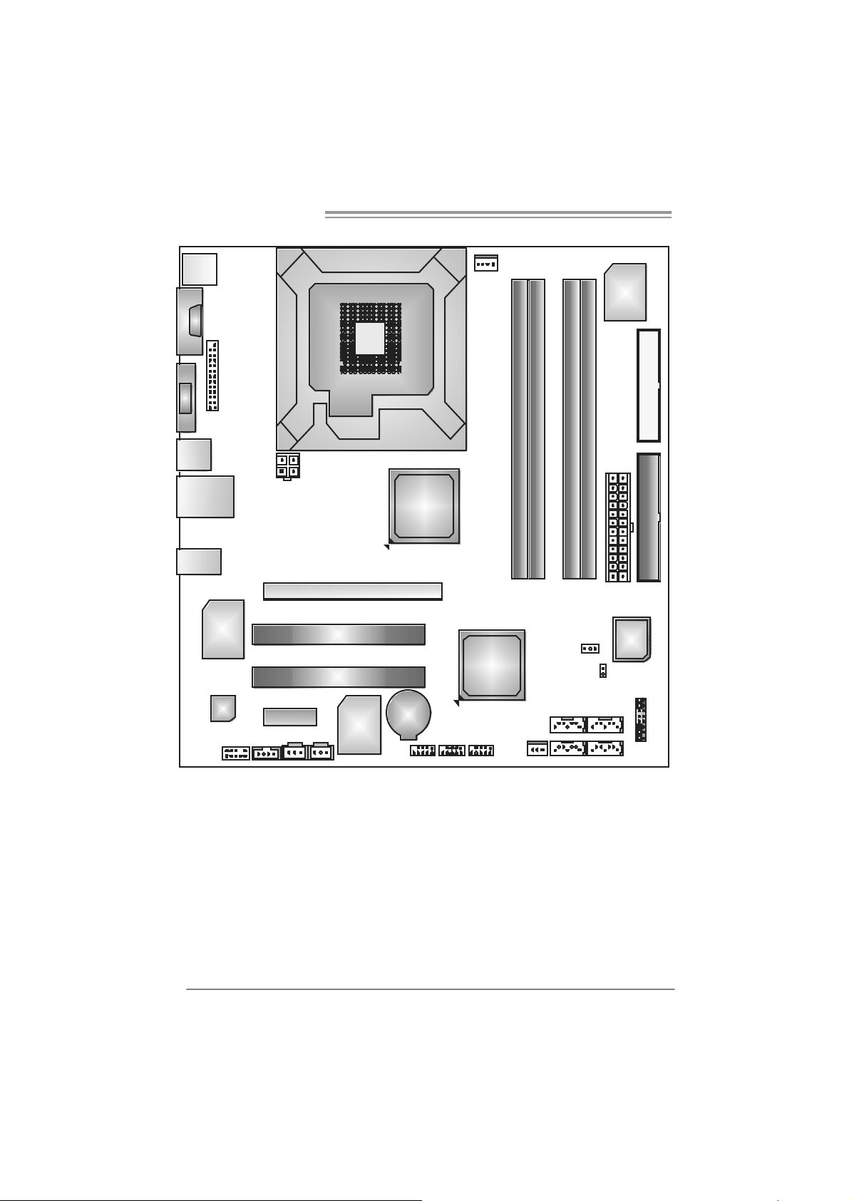
1.6 MOTHERBOARD LAYOUT (FOR VER 5.X)
J KBM S1
J
C
O
M
1
JVGA 1
JU S B1
JRJ45USB1
AUDIO1
JAUDIOF1
JPRNT1
LAN
Codec
JC DI N 1
JATXP WR1
PEX1_ 1
JS PDIF_OUT
LGA775
CP U1
PE X16_ 1
PC I 1
PC I 2
IDE
C ontr ol ler
JS PD IF _ I N( Opt ion al )
Note: ■ repre sents the 1st pin.
JC FAN1
Intel
G965
Intel
ICH8
BAT1
JUSB2 JUSB4 JUSB3 JSFAN1
DDR2_A 1
DDR2_A 2
SATA1 SATA2
SATA 3 SATA4
DDR2_B 1
JC MO S1
DDR2_B 2
J ATXPW R2
JCI1
(Optional)
Super
I/O
BI O S
FDD1IDE 1
JPANEL 1
5
Page 8
Motherboard Manual
1.7 MOTHERBOARD LAYOUT (FOR VER 6.X)
J KBM S1
JC OM 1
JVGA 1
JU S B1
JRJ45USB1
JA UD IO 2
JAUDIOF1
JPRNT1
LAN
Codec
JC DI N 1
JATXP WR1
PEX1_ 1
JS PDIF_OUT
LGA775
CP U1
PE X1 6_1
PC I 1
PC I 2
IDE
C ontr ol ler
JS PD IF _ I N( Opt ion al )
Note: ■ repre sents the 1st pin.
JC FAN1
Intel
G965
Intel
ICH8
BAT1
JUSB2 JUSB4 JUSB3 JSFAN1
DDR2_A 1
DDR2_A 2
SATA1 SATA2
SATA3 SATA4
DDR2_B 1
JC MOS1
DDR2_B 2
J ATXPW R2
JCI1
(Opti onal)
Super
I/O
BI O S
FDD1IDE 1
JPAN EL1
6
Page 9

G965 Micro 775
CHAPTER 2: HARDWARE INSTALLATION
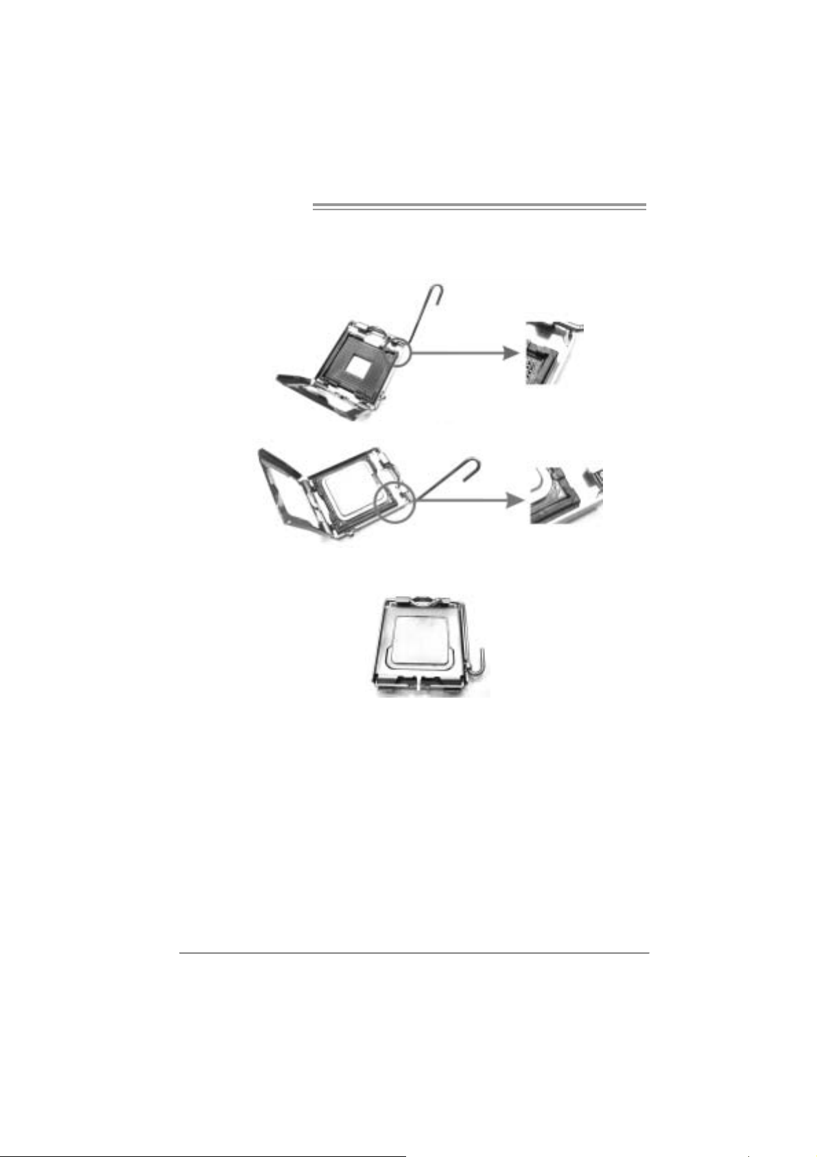
2.1 I
NSTALLING CENTRAL PROCESSING UNIT (CPU)
Special Notice:
Remo v e Pin Cap before installa tion, and m ake goo d preservation
for future use. When the CPU is remo ved, cov er the Pin Cap on the
empty so cket to ensure pin legs won’ t be da mag ed.
Pin-Cap
Step 1: Pull the socket locking lever out from the socket and then raise
the lever up to a 90-degree angle.
7
Page 10
Motherboard Manual
Step 2: Look for the triangular cut edge on socket, and the golden dot on
CPU should point forwards this triangular cut edge. The CPU will
fit only in the correct orientation.
Step 2-1:
Step 2-2:
Step 3: Hold the CPU down firmly, and then lower the lever to locked
position to complete the installation.
Step 4: Put the CPU Fan and heatsink assembly on the CPU and buckle it
on the retention frame. Connect the CPU FAN power cable into
the JCFAN1. This completes the installation.
8
Page 11
G965 Micro 775
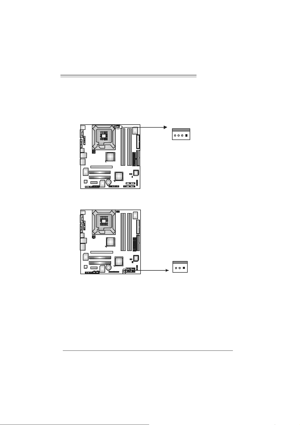
2.2 FAN HEADERS
These fan headers support cooling-fans built in the computer. The fan
cable and connector may be different according to the fan manufacturer.
Connect the fan cable to the connector while matching the black wire to
pin#1.
JCFAN1: CPU Fan Header
14
JCFAN1
JSF AN1 : Sy stem Fan H ead er
JSFAN1
Pin
Assignment
1 Ground
2 Power
3 FAN RPM
rate sense
4 Smart Fan
Control
Pin
Assignment
1 Ground
2 +12V
3 FAN RPM
rate sense
13
Note:
The J CF AN1 and JSFAN1 s up port 4-pi n and 3-pin head co nnec tor. W hen c onnecti ng
with wi r es onto c onn ect ors, pleas e no te tha t t he re d wire i s t he positi ve and s houl d be
conn ecte d t o pi n#2, and th e bl ac k wi re is Ground and s ho uld be c on nect ed to GND.
9
Page 12

Motherboard Manual
2.3 INSTALLING SYSTEM MEMORY
A. DDR2 mo d ule
DDR2_B2
DDR2_A2
DDR2_A1
DDR2_B1
1. Unlock a DIMM slot by pressing the retaining clips outward. Align a
DIMM on the slot such that the notch on the DIMM matches the
break on the Slot.
2. Insert the DIMM vertically and firmly into the slot until the retaining
chip snap back in place and the DIMM is properly seated.
10
Page 13
G965 Micro 775
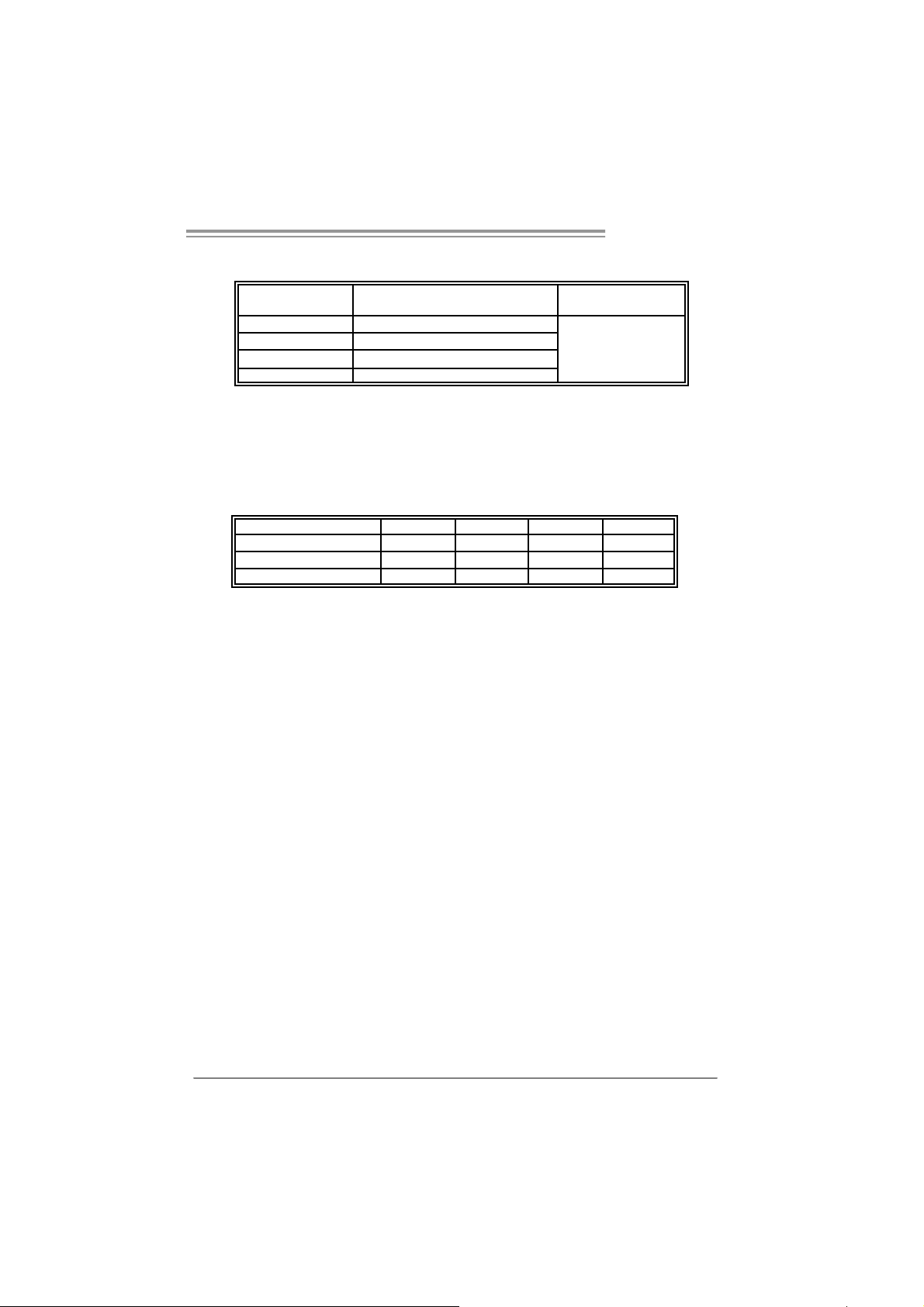
B. Memory Capacity
DI MM Socket
Location
DDR2_A1 256MB/512MB/1GB /2GB*1
DDR2_A2 256MB/512MB/1GB/2GB*1
DDR2_B1 256MB/512MB/1GB/2GB *1
DDR2_B2 256MB/512MB/1GB/2GB *1
C. Dual Channe l Me mory installation
To trigger the Dual Channel function of the motherboard, the memory
module must meet the following requirements:
Install memory module of the same density in pairs, shown in the
following table.
Du al Channel Status D DR2_A1 DDR2_A2 DDR2_B 1 DDR2_B 2
Enabled O X O X
Enabled X O X O
Enabled O O O O
(O means memory installed, X means memory not installed.)
The DRAM bus width of the memory module must be the same(x8 or x16)
DDR Module Total Memory Size
Max is 8GB.
11
Page 14
Motherboard Manual
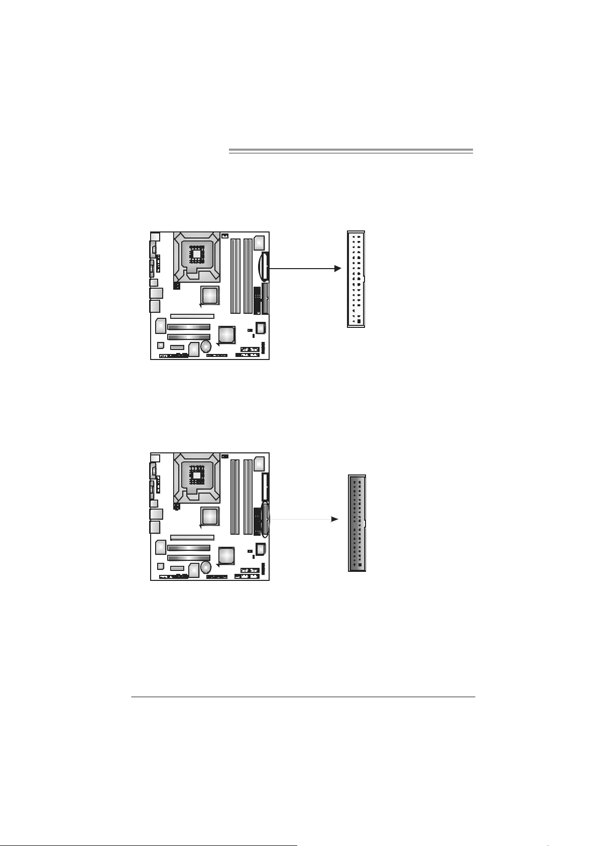
2.4 CONNECTORS AND SLOTS
FDD1: Floppy Disk Conne cto r
The motherboard prov ides a standard f loppy disk connector that supports 360K,
720K, 1.2M, 1.44M and 2.88M floppy disk ty pes. This connector supports the
prov ided f loppy drive ribbon cables.
34
33
2
1
IDE1: Hard Disk Connec tors
The motherboard has a 32-bit Enhanced PCI IDE Controller that provides PIO
Mode 0~4, Bus Master, and Ultra DMA 33/66/100/133 f unctionality.
The IDE connectors can connect a master and a slav e drive, so you can connect
up to four hard disk driv es. The f irst hard drive should always be connected to
IDE1.
IDE1
40
39
2
1
12
Page 15

G965 Micro 775
PEX16_1: PC I-Express x16 slots
- PCI-Express 1.0a compliant.
- Maximum theoretical realized bandwidt h of 4GB/s simultaneously per
direction, f or an aggregate of 8GB/s totally.
PEX1_1: PCI-Express x1 slots
- PCI-Express 1.0a compliant.
- Data transfer bandwidth up t o 250MB/s per direct ion; 500MB/s in total.
- PCI-Express supports a raw bit-rate of 2.5Gb/s on the data pins.
- 2X bandwidth ov er the traditional PCI architecture.
PEX16_1
PEX1_1
PCI1~PCI2: Peripheral Componen t Interconnect Sl o ts
This motherboard is equipped wit h 2 standard PCI slots. PCI stands f or
Peripheral Component Interconnect, and it is a bus standard for expansion
cards. This PCI slot is designated as 32 bits.
PCI1
PCI2
13
Page 16

Motherboard Manual
CHAPTER 3: HEADERS & JUMPERS SETUP
3.1 H
The illustration shows how to set up jumpers. When the jumper cap is
placed on pins, the jumper is “close”, if not, that means the jumper is
“open”.
OW TO SETUP JUMPERS
Pin opened Pin closed Pin1-2 closed
3.2 D
JPANEL1: Front Panel Header
ETAIL SETT INGS
This 22-pin connector includes Power-on, Reset, HDD LED, Power LED, Sleep
button, speaker and IrDA Connect ion. It allows user to connect the PC case’s
front panel switch f unctions.
816
On/Off RST
PWR_ LED
SLP
Pin Assignment Functio n Pin Assignment Function
1 +5V 9 Sleep control
2 N/A 10 Ground
3 N/A 11 N/A
4 Speaker
5 HDD LED (+) 13 Power LE D (+)
6 HDD LED (-)
7 Ground 15 Power button
8 Reset control
Speaker
Connector
Hard drive
LED
Reset button
12 P ow er LED (+)
14 P ow er LED (-)
16 Ground
-
-
+
++
19
Sleep button
N/A
Power LED
Power-on button
HLE D
SPK
14
Page 17

G965 Micro 775
JAT XPW R1: ATX Power Sou rce C on ne ctor
By connecting this connector, it will provide +12V to CPU power circuit.
34
12
JAT XPW R2: ATX Power Sou rce C on ne ctor
This connector allows user to connect 24-pin power connector on the ATX
power supply.
12
1
24
13
Pin
Assignment
1 +12V
2 +12V
3 Ground
4 Ground
Pin Assignment
1 +3.3V
2 +3.3V
3 Ground
4 +5V
5 Ground
6 +5V
7 Ground
8 PW_OK
9 Standby
Voltage +5V
10 +12V
11 +12V
12 2 x 12 Detect
13 +3.3V
14 -12V
15 Ground
16 PS_ON
17 Ground
18 Ground
19 Ground
20 -5V
21 +5V
22 +5V
23 +5V
24 Ground
15
Page 18

Motherboard Manual
JUS B 2/ JUS B3/JUSB 4: H eader s for USB 2. 0 P orts at F r o nt Pa n el
This motherboard prov ides 3 USB 2.0 headers, which allows us er to connect
additional USB cable on the PC front panel, and also can be connected with
internal USB dev ices, like USB card reader.
JUSB2/JUSB4/JUSB3
Pin Assignment
19
10 NC
1 +5V (fused)
2 +5V (fused)
3 USB4 USB5 USB+
6 USB+
7 Ground
8 Ground
9 Key
10
2
JAUDIOF1 : Front Panel Audio Header
This header allows user to connect the front audio output cable with the PC f ront
panel. It will disable the output on back panel audio connectors.
Pin Assignment
1 Mic in
2 Ground
3 Mic power
4 Audio power
5 Right line out
6 Right line out
7 Reserved
10 LFT Line Out
8 Key
9 Left line ou
210
19
JCDIN1: CD-R OM A ud io-i n Connector
This connector allows user to connect the audio source f rom the v ariaty devices,
like CD-ROM, D VD-ROM, PCI s ound card, PCI TV turner card etc..
Pin
Assignment
1 Left Channel
Input
2 Ground
3 Ground
4 Right
Channel
14
Input
16
Page 19

G965 Micro 775
JCMOS 1 : Clea r CMOS H ea der
By placing the jumper on pin2-3, it allows user to restore the BIOS saf e setting
and the CMOS data, please c arefully f ollow the procedures to avoid damaging
the motherboard.
13
Pin 1-2 Close:
Normal Operation
(Default).
3
1
13
Pin 2-3 Close:
Clear CMOS data.
※ Clear CMOS Procedures:
1. Remove AC power line.
2. Set the jumper to “Pin 2-3 close”.
3. Wait for f ive seconds.
4. Set the jumper to “Pin 1-2 close”.
5. Power on the AC.
6. Reset your desired password or clear the CMOS data.
JSATA1~ JS ATA4: Serial ATA Connectors
The motherboard has a PCI to SATA C ontroller with 4channels SATA interf ace, it
satisfies the SATA 2.0 spec and with transfer rate of 3Gb/s.
Pin Assignment
1 Ground
2 TX +
3 TX -
JSATA 1 JSATA2
147
JSATA 3 JSATA4
4 Ground
5 RX-
6 RX+
7 Ground
17
Page 20

Motherboard Manual
JSPDI F_O UT: Digital Au dio ou t C onnecto rs
This connector allows user to connect the PCI bracket SPDIF output header.
JSPDIF_IN: Di gital Audio in Connectors (optional )
This connector allows user to connect the PCI bracket SPDIF input header.
Pin
Assignment
1 +5V
2 SPDIF_OUT
3 Ground
13
Pin
Assignment
1 +5V
2 SPDIF_IN
3 Ground
JCI1: Chassis O pen Header (optional)
This connector allows syst em to monitor PC case open status. If the signal has
been triggered, it will record to the CMOS and show the message on next
boot-up.
18
3
1
Pin
Assignment
1 Case open signal
2 Ground
1
2
Page 21

G965 Micro 775
JPRNT1: Printer Port Connector
This header allows you to connector printer on the PC.
25
1
2
Pin Assignment Pin Assignment
1 -Strobe 14 Ground
2 -ALF 15 D ata 6
3 Data 0 16 Ground
4 -Error 17 D ata 7
5 Data 1 18 Ground
6 -Init 19 -AC K
7 Data 2 20 Ground
8 -Scltin 21 Busy
9 Data 3 22 Ground
10 Ground 23 PE
11 Data 4 24 Ground
12 Ground 25 SCLT
13 Data 5 26 Key
19
Page 22

Motherboard Manual
CHAPTER 4: USEFUL HELP
4.1 D
RIVER INSTALL ATION NOTE
After you installed your operating system, please insert the Fully Setup
Driver CD into your optical drive and install the driver for better system
performance.
You will see the following window after you insert the CD
The setup guid e will auto detect yo ur motherboard and operating system.
Note:
If this win do w didn’ t show up aft er yo u ins ert th e Dr iver CD, ple ase use fil e br o ws er to
locate and e xecu te the file SET U P.EXE un der your optical dr i ve.
A. Driver Insta llatio n
To install the driver, please click on the Driver icon. The setup guide will
list the compatible driver for your motherboard and operating system.
Click on each device driver to launch the installation program.
B. Software Installation
To install the software, please click on the Software icon. The setup guide
will list the software available for your system, click on each software title
to launch the installation program.
C. Manual
Aside from the paperback manual, we also provide manual in the Driver
CD. Click on the Manual icon to browse for available manual.
Note:
You will need Acrobat R eader to open the manual file. Pleas e download the latest version
of Acrobat R ead er soft ware from
http://www.adobe.com/products/acrobat /readstep2.html
20
Page 23

G965 Micro 775
4.2 AWARD BIOS BEEP CODE
One long beep followed by two short
beeps
High-low siren sound CPU overheated
One Short beep when system boot-up No error found during POST
Long beeps every other s econd N o DRAM detected or install
Beep Sound Meanin g
Video card not found or v ideo card
memory bad
System will shut down aut omatic ally
4.3 EXTRA INFORMATION
A. BIOS Update
After you fail to update BIOS or BIOS is invaded by virus, the
Boot-Block function will help to restore BIOS. If the following message
is shown after boot-up the system, it means the BIOS contents are
corrupted.
In this Case, please follow the procedure below to restore the BIOS:
1. Make a bootable floppy disk.
2. Download the Flash Utility “AWDFLASH.exe” from the Biostar
website: www.biostar.com.tw
3. Confirm motherboard model and download the respectively BIOS
from Biostar website.
4. Copy “AWDFLASH.exe” and respectively BIOS into floppy disk.
5. Insert the bootable disk into floppy drive and press Enter.
6. System will boot-up to DOS prompt.
7. Type “Awdflash xxxx.bf/ sn/py/ r” in DOS prompt.
(xxxx means BIOS name.)
8. System will update BIOS automatically and restart.
9. The BIOS h as been recove red and will work properly.
21
Page 24

Motherboard Manual
B. CPU Overheated
If the system shutdown automatically after power on system for
seconds, that means the CPU protection function has been activated.
When the CPU is over heated, the motherboard will shutdown
automatically to avoid a damage of the CPU, and the system may not
power on again.
In this case, please double check:
1. The CPU cooler surface is placed evenly with the CPU surface.
2. CPU fan is rotated normally.
3. CPU fan speed is fulfilling with the CPU speed.
After confirmed, please follow steps below to relief the CPU protection
function.
1. Remove the power cord from power supply for seconds.
2 . Wa i t f o r seco nd s.
3. Plug in the power cord and boot up the system.
Or you can:
1. Clear the CMOS data.
(See “Close CMOS Header: JCMOS1” section)
2 . Wa i t f o r seco nd s.
3. Po wer on the syst e m ag ai n.
22
Page 25

G965 Micro 775
e
4.4 TROUBLESHOOTING
1. No power to the system at all
Probable Solution
Power light don’t illuminate, f an
inside power supply does not turn
on.
2. Indicator light on key board does
not turn on.
System inoperativ e. Keyboard lights
are on, power indicator lights are lit,
and hard driv e is spinning.
System does not boot from hard disk
driv e, can be booted f rom optical driv e.
System only boots f rom optical driv e.
Hard disk can be read and applic ations
can be used but booting from hard disk
is impossible.
Screen message says “Invalid
Configuration” or “CMOS Failure. ”
Cannot boot system after installing
second hard driv e.
1. Make sure power cable is
securely plugged in.
2. Replace cable.
3. Contact technical support.
Using even pressure on bot h ends of
the DIMM, press down firmly until the
module snaps into place.
1. Check cable running from disk to
disk controller board. Make sure
both ends are securely plugged
in; c hec k t h e d riv e ty p e i n t he
standard CMOS setup.
2. Backing up the hard driv e is
extremely important. All hard
disks are capable of breaking
down at any tim e.
1. Back up data and applic ations
files.
2. Ref ormat the hard driv e.
Re-install applications and data
using backup disks.
Review sy stem’s equipment. Make sur
correct inf ormation is in setup.
1. Set master/slave jumpers
correctly.
2. Run SETUP program and select
correct driv e types. Call the drive
manufacturers for compatibility
with other drives.
23
Page 26

Motherboard Manual
CHAPTER 5: WARPSPEEDER™
5.1 INTRODUCTION
[WarpSpeeder™], a new powerful control utility, features three
user-friendly functions including Overclock Manager, Overvoltage
Manager, and Hardware Monitor.
With the Overclock Manager, users can easily adjust the frequency they
prefer or they can get the best CPU performance with just one click. The
Overvoltage Manager, on the other hand, helps to power up CPU core
voltage and Memory voltage. The cool Hardware Monitor smartly indicates
the temperatures, voltage and CPU fan speed as well as the chipset
information. Also, in the About panel, you can get detail descriptions about
BIOS model and chipsets. In addition, the frequency status of CPU,
memory, AGP and PCI along with the CPU speed are synchronically
shown on our main panel.
Moreover, to protect users' computer systems if the setting is not
appropriate when testing and results in system fail or hang,
[WarpSpeeder™] technology assures the sy stem stability by automatically
rebooting the computer and then restart to a speed that is either the
original system speed or a suitable one.
5.2 SYS TEM REQUIREMENT
OS Support: Windows 98 SE, Windows Me, Windows 2000, Windows XP
DirectX: DirectX 8.1 or above. (The Windows XP operating system
includes DirectX 8.1. If you use Windows XP, you do not need to install
DirectX 8.1.)
24
Page 27

G965 Micro 775
5.3 INSTALLATION
1. Execute the setup execution file, and then the following dialog will pop
up. Please click “Next” button and follow the default procedure to
install.
2. When you see the following dialog in setup procedure, it means setup
is completed. If the “Launch the WarpSpeeder Tray Utility” checkbox
is checked, the T ray Icon utili ty and [WarpSpeeder™] util ity will be
automatically and immediately launched after you click “Finish”
button.
Usage:
The following figures are just only for reference, the screen printed in
this user manual will change according to your m otherbo ard on hand.
25
Page 28

Motherboard Manual
5.4 WARPSPEEDER™
1. Tray Icon:
Whenever the Tray Icon utility is launched, it will display a little tray
icon on the right side of Windows Taskbar.
This utility is responsible for conveniently invoking [WarpSpeeder™]
Utility. You can use the mouse by clicking the left button in order to
invoke [WarpSpeeder™] directly from the little tray icon or you can
right-click the little tray icon to pop up a popup menu as following
figure. The “Launch Utility” item in the popup menu has the same
functio n as mouse l eft-click on tray i con and “Exit” item will cl ose
Tray Icon utility if selected.
26
Page 29

G965 Micro 775
2. Main Panel
If you cli ck the tray i con, [WarpSpeeder™] u tility will be invoked.
Please refer to the following figure; the utility’s first window you will
see is Main Panel.
Main Panel contains feature s as follows:
a . Di sp l a y t he CP U Sp ee d , CPU e x t e rnal clo c k, M em o ry cl o c k, AGP cl o c k,
and PCI clock information.
b. Contains About, Voltage, Overclock, and Hardware Monitor Buttons for
invoking respective panels.
c. With a user-friendly Status Animation, it can represent 3 overclock
percentage stages:
Man walking→overclock percentage from 100% ~ 110 %
Panther running→overclock percentage from 110% ~ 120%
Car racing→overclock percentage from 120% ~ above
27
Page 30

Motherboard Manual
3. Voltage Pa nel
Click the Voltage button in Main Panel, the button will be hi ghlighted
an d the Voltage Pane l will slide out to up as the following fig ure.
In this panel, you can decide to increase CPU core voltage and
Memory voltage or not. The default setting is “No”. If you want to get
the best performance of overclocking, we recommend you click the
option “Yes”.
28
Page 31

G965 Micro 775
4. Over clock Pa nel
Click the Overclock button in Main Pa nel, th e button will be
highlighted and the Overclock Panel will slide out to left as the
following figure.
Over clock Panel cont ains the the se fea ture s:
a. “–3MHz button”, “-1MHz button”, “+1MHz button”, and “+3MHz button”:
provide user the ability to do real-time overclock adjustment.
Warning:
Manually overclock is potentially dangerous, especially when the
ov erclocking percentage is over 110 %. We strongly recommend you
v erify ev ery speed you overclock by click the Verify button. Or, you can
just click Auto ov erc lock button and let [WarpSpeeder™] automatically
gets the best result f or y ou.
b. “Recovery Dialog button”: Pop up the following dialog. Let user select
a restoring way if system need to do a fail-safe reboot.
29
Page 32

Motherboard Manual
c. “Auto-overclock button”: User can click this button and
[WarpSpeeder™] will set the be st and stable pe rfo rman ce and
frequency automatically. [WarpSpeeder™] utility will execute a
se ries of testing until system fail . Then system will do fa il-safe
reboot by using Watchdog function. After reboot, the
[WarpSpeeder™] utility will restore to the hardware default
setting or load the verified best and stable frequency according
to the Recovery Dialog’s setting.
d. “Verify button”: User can click this button and [WarpSpeeder™]
will proceed a testing for current frequency. If the testing is ok,
then the current frequency will be saved into system registry. If
the testing fail, system will do a fail-safe rebooting. After reboot,
the [WarpS peeder™] uti li ty will restore to the hardware default
setting or load the verified best and stable frequency according
to the Recovery Dialog’s setting.
Note:
Because the testing programs, invoked in Auto-overcloc k and Verify,
include DirectDraw, Direct3D and DirectShow tests, the DirectX 8.1 or
newer runtime library is required. And please make sure y our display
card’s color depth is High color (16 bit) or True color( 24/32 bit ) that is
required f or Direct3D rendering.
5. Hardware Monitor Panel
Click the Hardware Monitor button in Main Panel, the button will be
highlighted and the Hardware Monitor panel will slide out to left as
the following figure.
In this panel, you can get the real-time status information of your
sy stem . The i n formati on will be refreshed every 1 second.
30
Page 33

G965 Micro 775
6. About Panel
Click the “about” button in Main Panel, the button will be highlighted
and the About Panel will slide out to up as the following figure.
In this panel, you can get model name and detail information in hints
of all the chipset that are related to overclocking. You can also get
the mainboard’s BIOS model and the Version number of
[WarpSpeeder™] utility.
Note:
Because the overclock, overvoltage, and hardware monitor features
are controlled by several separate chipset, [WarpSpeeder™] divide
these features to separate panels. If one chipset is not on board, the
co rrel ati ve butto n in Main pa n el will be disabl ed, but wil l not interf e re
other panels’ functions. This property can make [WarpSpeeder™]
utili ty mo re robust.
31
Page 34

Motherboard Manual
APPEN DENCIES : SPEC IN OTHER LAN GUAGE
GERMAN
Ver 5.x Ver 6.x
LGA 775
Int el Core2Duo / Core2Quad / Pentium 4 /
Pentium D / Celeron D Prozessor en m it bis zu
CPU
FSB 533 / 800 / 1066 MHz 533 / 800 / 1066 M Hz
Chipsatz
Super E/A
Arbeitss pei ch
er
Grafi k
IDE
SA TA II
3,8 GHz
Unterstützt Hyper-Threading / Execute Disable
Bit / Enhanced Intel SpeedStep® / Intel
Architecture-64 / Extended Memory 64
Technology / Virtualization Technology
Int el G965
Intel ICH8
ITE 8712F
Bi etet die häufig verw endeten alten Super
E/A-Funktionen.
Low Pin Count-Schnittstelle
Umgebungskontrolle,
Hardware-Überwac hung
Lüfterdrehzahl-Controller
"Smart Guardian"-Funktion von ITE
DDR2 DIMM -S teckplätz e x 4
Jeder DIMM unterstützt 256/512MB/ 1GB/2GB
DDR2.
M ax. 8GB A r beit sspeic her
Dual-Kanal DDR2 Speic hermodul
Unt er stützt DDR2 533 / 667 / 800 regist rierte
DIMMs. ECC DIMMs werden nicht unterstützt.
GMA X 3000
Max. 384MB gemeinsam benutzter
Videospeicher
VT6410 IDE-Controller
Unterstützt PIO-Modus 0~4
Ultra DM A 33 / 66 / 100 / 133 B us
Master-Modus
Integrierter Serial ATA II Controller
Konform mit der SATA-Spezifikation Version 2.0.
Datentrans ferrate bis zu 3.0Gb/s
LGA 775
Int el Core2Duo / Core2Quad / Pentium 4 /
Pentium D / Celeron D Prozessor en m it bis zu
3,8 GHz
Unterstützt Hyper-Threading / Execute Disable
Bit / Enhanced Intel SpeedStep® / Intel
Architecture-64 / Extended Memory 64
Technology / Virtualization Technology
Int el G965
Intel ICH8
ITE 8712F
Bi etet die häufig verw endeten alten Super
E/A-Funktionen.
Low Pin Count-Schnittstelle
Umgebungskontrolle,
Hardware-Überwac hung
Lüfterdrehzahl-Controller
"Smart Guardian"-Funktion von ITE
DDR2 DIMM -S teckplätz e x 4
Jeder DIMM unterstützt 256/512MB/ 1GB/2GB
DDR2.
M ax. 8GB A r beit sspeic her
Dual-Kanal DDR2 Speic hermodul
Unt er stützt DDR2 533 / 667 / 800 regist rierte
DIMMs. ECC DIMMs werden nicht unterstützt.
GMA X 3000
Max. 384MB gemeinsam benutzter
Videospeicher
VT6410 IDE-Controller
Unterstützt PIO-Modus 0~4
Ultra DM A 33 / 66 / 100 / 133 B us
Master-Modus
Integrierter Serial ATA II Controller
Konform mit der SATA-Spezifikation Version 2.0.
Datentrans ferrate bis zu 3.0Gb/s
32
Page 35

G965 Micro 775
Ver 5.x Ver 6.x
Realtek RTL 8110SC
10 / 100 Mb/s und 1Gb/s Aut o-Negotiation
Halb-/ Vollduplex-Funktion
ALC861VD
Unterstützt High-Definition Audio
5.1-K anal-A udioaus gabe
PS/2-Tastatur x1
PS/2-Maus x1
VGA-Anschluss x1
Serie ller A nsc hluss x1
LAN-A nschl uss x1
US B-A nschluss x4
Audi oansc hl uss x 3
Wi ndows 2000 / XP / VISTA
Biostar behält sich das Recht vor, ohne
Ankündigung die Unterst ützung für ei n
Betriebssystem hinzuz ufügen oder zu
entfernen.
LAN
Audio-Codec
Onboard-Ans
chluss
Rückseiten-E
/A
Platinengröße
.
OS-Unterstüt
zung
Realtek RTL 8110SC
10 / 100 Mb/s und 1Gb/s Aut o-Negotiation
Halb-/ Vollduplex-Funktion
ALC888
Unterstützt High-Definition Audio
7.1-K anal-A udioaus gabe
PCI Express x16-St eckplatz x1 PCI Express x16-Stec kplat z x1
PCI Express x1-Steckplatz x1 PCI Express x1-Steckplatz x1 Steckplätze
PCI-Steckplatz x2 PCI-Steckplatz x2
Diskette nl aufw er kansc hluss x 1 Di ske ttenlaufw er kansc hluss x1
IDE-A nschluss x1 IDE- Ansc hl uss x1
SATA II-Ansc hl uss x4 SATA II-Anschl uss x4
Fronttafelanschluss x1 Fronttafelanschluss x1
Fr ont-A udioansc hl uss x1 F ro nt -Audioansc hluss x1
CD-I N-Ansc hl uss x 1 CD-I N-Ansc hl uss x 1
S/PDIF- Ausgangsanschluss x1 S/PDIF- Ausgangsansc hluss x1
S/PDIF Eingangs anschluss (opt ional) x1 S/PDIF Eingangs anschluss (opt ional) x1
CPU-Lüfter-Sockel x1 CPU-Lüfter-Sockel x1
System-Lüfter-Sockel x1 System-Lüfter-Sockel x1
"Gehäuse offen"-Sockel (optional) x1 "Gehäuse offen"-Sockel (optional) x1
"CMOS löschen"-Soc kel x1 "CMOS löschen"-Sockel x1
US B-A nschluss x3 US B-A nschluss x3
Druc kera nsc hluss Anschluss x1 Druc kera nsc hluss Anschluss x1
Stromanschluss (24-polig) x1 Stromanschluss (24-polig) x1
Stromanschluss (4-polig) x1 Stromanschluss (4-polig) x1
PS/2-Tastatur x1
PS/2-Maus x1
VGA-Anschluss x1
Serie ller A nsc hluss x1
LAN-A nschl uss x1
US B-A nschluss x4
Audi oansc hl uss x 6
243 mm (B) X 243 mm (L) 243 mm (B) X 243 mm (L)
Wi ndows 2000 / XP / VISTA
Biostar behält sich das Recht vor, ohne
Ankündigung die Unterst ützung für ei n
Betriebssystem hinzuz ufügen oder zu
entfernen.
33
Page 36

Motherboard Manual
FRANCE
Ver 5.x Ver 6.x
LGA 775
Processeurs Intel Core2Duo / Core2Quad /
Pentium 4 / Pentium D / Celeron D jusqu'à 3,8
GHz
UC
Bus frontal 533 / 800 / 1066 MHz 533 / 800 / 1066 MHz
Chipset
Super E/S
Mémoire
principal e
Graphiques
IDE
SA TA II
Prend en charge les technologies
Hyper-Threading / d'exécution de bit de
désactivation / Intel SpeedStep® optimisée/
d'architecture Intel 64 / de m ém oire ét endue 64
/ de virt ualisation
Int el G965
Intel ICH8
ITE 8712F
Four nit la fonctionnalité de S uper E/S
patrimoniales la plus utilisée.
Interface à faible compte de broches
Initiatives de contrôle envi ronnement ales,
Monit eur de m at ériel
Contrôleur de vitess e de ventilateur
Fonction "Gardien intelligent" de l'ITE
Fentes DDR2 DIM M x 4
Chaque DIMM prend en c harge des DDR2 de
256/512 Mo et 1Go/2Go
Capacité mémoire maximale de 8 Go
Modul e de mémoire DDR 2 à m ode à double voie
Prend en charge l a DDR 2 533 / 667 / 800
Les DIMM à registres et DIMM sans code
correc teurs d'erreurs ne sont pas prises en
charge
GMA X 3000
Mémoire vidéo partagée maximale de 384 Mo
VT6410 Contrôleur IDE
Prend en charge le mode PIO 0~4,
Mode principale de Bus Ult ra DMA 33 / 66 / 100 /
133
Cont r ôl eur Se rial ATA
Conforme à la spécification SATA Version 2.0
Taux de transfert jusqu'à 3.0 Go/s.
II
intégré :
34
LGA 775
Processeurs Intel Core2Duo / Core2Quad /
Pentium 4 / Pentium D / Celeron D jusqu'à 3,8
GHz
Prend en charge les technologies
Hyper-Threading / d'exécution de bit de
désactivation / Intel SpeedStep® optimisée/
d'architecture Intel 64 / de m ém oire ét endue 64
/ de virt ualisation
Int el G965
Intel ICH8
ITE 8712F
Four nit la fonctionnalité de S uper E/S
patrimoniales la plus utilisée.
Interface à faible compte de broches
Initiatives de contrôle envi ronnement ales,
Monit eur de m at ériel
Contrôleur de vitess e de ventilateur
Fonction "Gardien intelligent" de l'ITE
Fentes DDR2 DIM M x 4
Chaque DIMM prend en c harge des DDR2 de
256/512 Mo et 1Go/2Go
Capacité mémoire maximale de 8 Go
Modul e de mémoire DDR 2 à m ode à double voie
Prend en charge l a DDR 2 533 / 667 / 800
Les DIMM à registres et DIMM sans code
correc teurs d'erreurs ne sont pas prises en
charge
GMA X 3000
Mémoire vidéo partagée maximale de 384 Mo
VT6410 Contrôleur IDE
Prend en charge le mode PIO 0~4,
Mode principale de Bus Ult ra DMA 33 / 66 / 100 /
133
Cont r ôl eur Se rial ATA
Conforme à la spécification SATA Version 2.0
Taux de transfert jusqu'à 3.0 Go/s.
II
intégré :
Page 37

G965 Micro 775
Ver 5.x Ver 6.x
LAN
Codec audio
Connec teur
embarqué
E/S du
panneau
arrière
Dim ensions
de la cart e
Support SE
Realtek RTL 8110SC
10 / 100 M b/s et 1 Gb/s négociation automatique
Half / Full duplex capability
ALC888
Prise en charge de l'audio haute définition
Sortie audio à 7. 1 voies
Fente PCI Express x16 x1 Fente PCI Express x16 x1
Fente PCI Express x1 x1 Fente PCI Express x1 x1 Fentes
Fente PCI x2 Fente PCI x2
Connec teur de disquett e x1 Connec teur de disquette x1
Connec teur I DE x1 Connec teur I DE x1
Connec teur SATA II x4 Connec teur SATA II x4
Connec teur du panneau avant x1 C onnecteur du panneau avant x1
Connec teur A udi o du panneau avant x1 Connecteur Audio du panneau avant x1
Connecteur d'entrée CD x1 Connecteur d'entrée CD x1
Connecteur de sortie S/PDIF x1 Connecteur de sortie S/PDIF x1
Connecteur d'entrée S/PDIF x1
(en option)
Embase de ventilateur UC x1 Embase de ventilateur UC x1
Embase de ventilateur s yst èm e x1 Embase de ventilateur s ystème x1
Embase d' ouverture de châssi s(en opt ion) x1 Embase d'ouverture de c hâssis(en opt ion) x1
Embas e d'effacem ent CMO S x1 Embas e d'effacement CMOS x1
Connec teur USB x3 Connec teur US B x3
Connec teur de
Port d'imprimante x1
Connecteur d'alimentation x1
(24 broches)
Connecteur d'alimentation x1
(4 broches)
Clavier PS/2 x1
Souris PS/2 x1
Port série x1
Port VGA x1
Port LA N x1
Port USB x4
Fiche audio x6
243 mm (l) X 243 mm (H) 243 m m (l) X 243 m m (H)
Wi ndows 2000 / XP / VISTA
Biostar se réserve le droit d'ajouter ou de
supprimer le support de SE avec ou sans préavis.
Realtek RTL 8110SC
10 / 100 M b/s et 1 Gb/s négociation automatique
Half / Full duplex capability
ALC861VD
Prise en charge de l'audio haute définition
Sortie audio à 5. 1 voies
Connecteur d'entrée S/PDIF x1
(en option)
Connec teur de
Port d'imprimante x1
Connecteur d'alimentation x1
(24 broches)
Connecteur d'alimentation x1
(4 broches)
Clavier PS/2 x1
Souris PS/2 x1
Port série x1
Port VGA x1
Port LA N x1
Port USB x4
Fiche audio x3
Wi ndows 2000 / XP / VISTA
Biostar se réserve le droit d'ajouter ou de
supprimer le support de SE avec ou sans préavis.
35
Page 38

Motherboard Manual
/
/
/
/
pp
p
ITALIAN
Ver 5.x Ver 6.x
LGA 77 5
Processore Intel Core2Duo / Core 2Quad /
Pentium 4 / Pentium D / Celeron D fi no a 3. 8
CPU
FS B 533 / 800 / 1066 MHz 533 / 800 / 106 6 MHz
Chipset
Super I/O
Memoria
principale
Grafica
IDE
SATA II
GHz
Suppor to di Hyper -T hreadi ng / Execute
Dis able Bit
Architettura Intel 64
Memory 6 4 / Tec nologia Virtualization
Int el G965
Intel ICH8
ITE 8712F
Fornisce le f unzio nalità legacy Sup er I/O
usate più comunemente.
Interfaccia LPC (L ow Pin Count)
Funzioni di co ntrollo dell’ambiente:
Monitoraggio h ardware
Controller velocità ventolin a
Funz ione "Smar t Guardi an" di I TE
Al loggi DIMM DDR 2 x 4
Ciascun DIMM su
1GB/2GB
Capacità massima della memori a 8GB
Modulo di memoria DDR 2 a canale doppi o
Supporto di DDR2 533 / 667 / 800
DIMM registrati e DIMM ECC sono
supportati
GMA X3000
La memoria vi deo condivisa massima è di
384MB
VT6410 Co ntroller I DE
Suppor to modalità PIO Mode 0- 4
Modalità Bus Master Ultra DMA 33 / 66 /
100 / 13 3
Controller Serial ATA II integrato
Compatibile specifiche SATA Versione 2.0.
Veloc ità di t rasferiment o dei dat i fi no a 3. 0
Gb/s .
E nha nced I ntel Spee dStep® /
Tecnologia Extended
ort a DDR 2 256/51 2MB e
36
LGA 77 5
Processore Intel Core2Duo / Core 2Quad /
Pentium 4 / Pentium D / Celeron D fi no a 3. 8
GHz
Suppor to di Hyper -T hreadi ng / Execute
Dis able Bit
Architettura Intel 64
Memory 6 4 / Tec nologia Virtualization
Int el G965
Intel ICH8
ITE 8712F
Fornisce le f unzio nalità legacy Sup er I/O
usate più comunemente.
Interfaccia LPC (L ow Pin Count)
Funzioni di co ntrollo dell’ambiente:
Monitoraggio h ardware
Controller velocità ventolin a
Funz ione "Smar t Guardi an" di I TE
Al loggi DIMM DDR 2 x 4
Ciascun DIMM sup
1GB/2GB
Capacità massima della memori a 8GB
Modulo di memoria DDR 2 a canale doppi o
Supporto di DDR2 533 / 667 / 800
DIMM registrati e DIMM ECC sono
supportati
GMA X3000
La memoria vi deo condivisa massima è di
384MB
VT6410 Co ntroller I DE
Suppor to modalità PIO Mode 0- 4
Modalità Bus Master Ultra DMA 33 / 66 /
100 / 13 3
Controller Serial ATA II integrato
Compatibile specifiche SATA Versione 2.0.
Veloc ità di t rasferiment o dei dat i fi no a 3. 0
Gb/s .
E nha nced I ntel Spee dStep® /
Tecnologia Extended
ort a DDR 2 256/51 2MB e
Page 39

G965 Micro 775
Ver 5.x Ver 6.x
LAN
Codec
audio
Alloggi
Connett ori
su scheda
I/O
pannello
posteriore
Dim ension
i scheda
Sistemi
operativi
supportati
Realtek RTL 8110SC
Negozi azione automati ca 10 / 10 0 Mb /s e
1Gb/s
Capacità Half / Full Duplex
ALC888
Supporto audio High-Definition (HD)
Uscita audio 7.1 canali
Al loggio PCI Ex press x1 6 x1 A lloggio PC I Express x16 x1
Al loggio PCI Ex press x1 x1 Alloggio PC I Ex pres s x1 x1
Alloggio PCI x2 Alloggio PCI x2
Connett ore floppy x1 C onnet tore flo ppy x1
Connett ore IDE x1 Connett ore IDE x1
Connettore SATA II x4 Connettore SATA II x4
Connett ore pa nnello fro ntale x1 Connett ore pa nnello fro ntale x1
Connettore audio frontale x1 Connettore audio frontale x1
Connettore CD-in x1 Connettore CD-in x1
Connettore output SPDIF x1 Connettore outp ut SPDIF x1
Connettore input S/PDIF x1
(optional)
Collettore ventolina CPU x1 Collettore ventolin a CPU x1
Collettore ventolina sistema x1 Collettore ventolina sistema x1
Collettore apertur a telaio(optional) x1 Collettore apertur a telaio( option al) x1
Collettore cancellazione CMOS x1 Collettore cancellazione CMOS x1
Connett ore US B x3 C onnet tore USB x3
Connett ore Porta st ampa nte x1 C onnet tore Port a s tampa nte x1
Connettore alimentazione x1
(24 pin)
Connettore alimentazione x1
(4 pin)
Ta s t i er a P S /2 x 1
Mouse PS/2 x1
Porta seriale x1
Porta VGA x1
Porta LAN x1
Porta USB x4
Connett ore au dio x6
243 mm (lar ghezza) x 243 mm (altez za) 243 mm (larghezza) x 243 mm (altezza)
Windows 2000 / XP / VISTA
Biostar si riserva il diritto di ag giungere o
rimuovere il supporto di qualsiasi sistema
operativo senza pre avviso.
Realtek RTL 8110SC
Negozi azione automati ca 10 / 10 0 Mb /s e
1Gb/s
Capacità Half / Full Duplex
ALC861VD
Supporto audio High-Definition (HD)
Uscita audio 5.1 canali
Connettore input S/PDIF x1
(optional)
Connettore alimentazione x1
(24 pin)
Connettore alimentazione x1
(4 pin)
Ta s t i er a P S /2 x 1
Mouse PS/2 x1
Porta seriale x1
Porta VGA x1
Porta LAN x1
Porta USB x4
Connett ore au dio x3
Windows 2000 / XP / VISTA
Biostar si riserva il diritto di ag giungere o
rimuovere il supporto di qualsiasi sistema
operativo senza pre avviso.
37
Page 40

Motherboard Manual
SPANISH
Ver 5.x Ver 6.x
LGA 775
Procesador Intel Core2Duo / Core2Quad /
Pentium 4 / Pentium D / Celeron D hasta 3,8 GHz
CPU
FSB 533 / 800 / 1066 MHz 533 / 800 / 1066 MHz
Conjunto de
chips
Súper E/S
Memoria
principal
Gráficos
IDE
SA TA II
Admite Hyper-Threading / Bit de deshabilitaci ón
de ejec uc ió n / Intel S pee dSt ep® Mejorado / I ntel
Architecture-64 / Tecnología Extended Memory
64 / Tecnología de virtualiz ac ión
Int el G965
Intel ICH8
ITE 8712F
Le ofrece las funcional idades heredadas de uso
más común Súper E/S.
Interfaz de cuenta Low Pin
Iniciativas de control de entorno,
Monitor hardware
Controlador de velocidad de ventilador
Función "Guardia inteligente" de ITE
Ranuras DIMM DDR2 x 4
Cada DIMM admit e DDR de 256/512MB y
1GB/2GB
Capacidad máxima de memoria de 8GB
Módul o de m em oria DDR 2 de canal Doble
Admite DDR2 de 533 / 667 / 800
No admite DIMM registrados o DIMM no
compatibles con ECC
GMA X 3000
Memoria máxima de vídeo compartida de
384MB
VT6410 Controlador I DE
Soport e los Modos PIO 0~4,
Modo bus m aestro Ultr a DMA 33 / 66 / 100 / 133
Controlador ATA II Serie Integrado
Compatible c on la versión SATA 2.0.
Tasas de transferencia de hasta 3.0 Gb/s.
LGA 775
Procesador Intel Core2Duo / Core2Quad /
Pentium 4 / Pentium D / Celeron D hasta 3,8 GHz
Admite Hyper-Threading / Bit de deshabilitaci ón
de ejec uc ió n / Intel S pee dSt ep® Mejorado / I ntel
Architecture-64 / Tecnología Extended Memory
64 / Tecnología de virtualiz ac ión
Int el G965
Intel ICH8
ITE 8712F
Le ofrece las funcional idades heredadas de uso
más común Súper E/S.
Interfaz de cuenta Low Pin
Iniciativas de control de entorno,
Monitor hardware
Controlador de velocidad de ventilador
Función "Guardia inteligente" de ITE
Ranuras DIMM DDR2 x 4
Cada DIMM admit e DDR de 256/512MB y
1GB/2GB
Capacidad máxima de memoria de 8GB
Módul o de m em oria DDR 2 de canal Doble
Admite DDR2 de 533 / 667 / 800
No admite DIMM registrados o DIMM no
compatibles con ECC
GMA X 3000
Memoria máxima de vídeo compartida de
384MB
VT6410 Controlador I DE
Soport e los Modos PIO 0~4,
Modo bus m aestro Ultr a DMA 33 / 66 / 100 / 133
Controlador ATA II Serie Integrado
Compatible c on la versión SATA 2.0.
Tasas de transferencia de hasta 3.0 Gb/s.
38
Page 41

G965 Micro 775
Ver 5.x Ver 6.x
Red Local
Códecs de
sonido
Conectores
en placa
Panel
trasero de
E/S
Ta m añ o d e
la placa
Soport e de
sistema
operat ivo
Realtek RTL 8110SC
Negociac ión de 10 / 100 Mb/s y 1 Gb/s
Funciones Hal f / Full dúplex
ALC888
Soport e de sonido Alta Definic ión
Salida de s onido de 7. 1 canales
Ranura PCI Express x16 X1 R anura PCI Express x16 X1
Ranura PCI Express x1 X1 R anura PCI Express x1 X 1 Ranuras
Ranura PCI X2 R anura PCI X 2
Conector disco flexible X1 Conector disco flexible X1
Conector IDE X1 Conector IDE X1
Conec tor SATA II X 4 Conec tor SATA II X4
Conect or de panel front al X1 Conect or de panel front al X1
Conector de sonido frontal X1 Conector de sonido frontal X1
Conector de entrada de CD X 1 Conector de entrada de CD X1
Conector de salida S/PDIF X1 Conector de salida S/PDIF X1
Conector de entrada S/PDIF x1
(opcional)
Cabecera de ventil ador de CPU X1 Cabec era de vent ilador de CPU X1
Cabecera de ventil ador de s ist ema X1 Cabecera de vent ilador de sistema X1
C abec era d e c hasis ab ierto ( opcio nal ) X 1 C abecera de chas is abie rt o ( opc ion al) X1
Cabecera de borrado de CMOS X 1 Cabecera de borrado de CMOS X 1
Conector USB X3 Conector USB X3
C o nec tor Puer t o de im p r es ora X 1 C onec t or Pu ert o de im p r es ora X 1
Conector de alimentación X1
(24 pat illas)
Conector de alimentación X1
(4 patillas)
Te c l ad o P S/ 2 X 1
Ratón PS/2 X1
Puerto serie X1
Puerto VGA X1
Puerto de red local X1
Puerto USB X4
Conector de sonido X6
243 mm. (A) X 243 Mm. (H) 243 m m. (A) X 243 Mm. (H)
Wi ndows 2000 / XP / VISTA
Biostar se reserva el derecho de añadir o retirar
el soporte de cualquier SO con o sin aviso previo.
Realtek RTL 8110SC
Negociac ión de 10 / 100 Mb/s y 1 Gb/s
Funciones Hal f / Full dúplex
ALC861VD
Soport e de sonido Alta Definic ión
Salida de s onido de 5. 1 canales
Conector de entrada S/PDIF x1
(opcional)
Conector de alimentación X1
(24 pat illas)
Conector de alimentación X1
(4 patillas)
Te c l ad o P S/ 2 X 1
Ratón PS/2 X1
Puerto serie X1
Puerto VGA X1
Puerto de red local X1
Puerto USB X4
Conector de sonido X6
Wi ndows 2000 / XP / VISTA
Biostar se reserva el derecho de añadir o retirar
el soporte de cualquier SO con o sin aviso previo.
39
Page 42

Motherboard Manual
PORTUGUESE
Ver 5.x Ver 6.x
LGA 775
Processador Intel Core2Duo / Core2Quad /
Pentium 4 / Pentium D / Celeron D até 3,8 GHz
CPU
FSB 533 / 800 / 1066 MHz 533 / 800 / 1066 MHz
Chipset
Es pec ificaçã
o Super I/O
Memória
principal
Plac a
gráfica
IDE
SA TA II
Suporta as tecnologias Hyper-Threading /
Execute Disable Bit / Enhanc ed Intel
SpeedS tep® / Int el A rquitect ure -64 / Extended
Memory 64 / Virtualization
Int el G965
Intel ICH8
ITE 8712F
Proporciona as funcionalidades mais utilizadas
em termos da es peci ficaç ão Super I/O.
Int erfac e LPC (Low Pin Count ).
Iniciativas para controlo do ambiente
Monit oriz ação do hardware
Controlador da velocidade da ventoinha
Função "Smart Guardian" da ITE
Ranhuras DIMM DDR2 x 4
Cada módulo DIMM suporta uma memória
DDR2 de 256/512 MB & 1GB/2GB
Capacidade m áxima de m emóri a: 8 GB
Módulo de m em ória DDR2 de canal duplo
Suporta m ódul os DDR2 533 / 667 / 800
Os m ódulos DIM M regist ados e os DI MM ECC são
suportados
GMA X 3000
Memória de ví deo máxima partil hada: 384 MB
VT6410 Controlador I DE
Suporta o modo PIO 0~4,
Modo Bus master Ultra DMA 33 / 66 / 100 / 133
Controlador S erial ATA II integrado
Compatibilidade com a especificação SATA
v e rs ã o 2. 0.
Velocidades de transmissão de dados até 3.0
Gb/s.
LGA 775
Processador Intel Core2Duo / Core2Quad /
Pentium 4 / Pentium D / Celeron D até 3,8 GHz
Suporta as tecnologias Hyper-Threading /
Execute Disable Bit / Enhanc ed Intel
SpeedS tep® / Int el A rquitect ure -64 / Extended
Memory 64 / Virtualization
Int el G965
Intel ICH8
ITE 8712F
Proporciona as funcionalidades mais utilizadas
em termos da es peci ficaç ão Super I/O.
Int erfac e LPC (Low Pin Count ).
Iniciativas para controlo do ambiente
Monit oriz ação do hardware
Controlador da velocidade da ventoinha
Função "Smart Guardian" da ITE
Ranhuras DIMM DDR2 x 4
Cada módulo DIMM suporta uma memória
DDR2 de 256/512 MB & 1GB/2GB
Capacidade m áxima de m emóri a: 8 GB
Módulo de m em ória DDR2 de canal duplo
Suporta m ódul os DDR2 533 / 667 / 800
Os m ódulos DIM M regist ados e os DI MM ECC são
suportados
GMA X 3000
Memória de ví deo máxima partil hada: 384 MB
VT6410 Controlador I DE
Suporta o modo PIO 0~4,
Modo Bus master Ultra DMA 33 / 66 / 100 / 133
Controlador S erial ATA II integrado
Compatibilidade com a especificação SATA
v e rs ã o 2. 0.
Velocidades de transmissão de dados até 3.0
Gb/s.
40
Page 43

G965 Micro 775
Ver 5.x Ver 6.x
LAN
Codec de
som
Ranhuras
Conectores
na plac a
Entradas/S
aídas no
painel
traseiro
Tam anho
da placa
Sistemas
operat ivos
suportados
Realtek RTL 8110SC
Auto negociação de 10 / 100 Mb/s e 1 Gb/s
Capacidade semi/full-duplex
ALC888
Suporta a es pecificação High-Definition A udio
Saída de áudio de 7.1 canais
Ranhura PCI Express x16 x1 Ranhura PCI Express x16 x1
Ranhura PCI Express x1 x1 Ranhura PCI Express x1 x1
Ranhura PCI x2 R anhura PCI x2
Conect or da unidade de disquetes x1 Conector da unidade de disquetes x1
Conector IDE x1 Conector IDE x1
Conec tor SATA II x4 C onec t or SATA II x4
Conect or do painel frontal x1 Conector do painel frontal x1
Conec tor de áudi o frontal x1 Conec tor de áudio frontal x1
Conector para entrada de CDs x1 Conec tor para entrada de CDs x1
Conector de saída S/PDIF x1 Conector de saída S/PDIF x1
Conector de entrada S/PDIF (opc ional) x1 Conector de entrada S/PDIF (opcional) x1
Conec tor da ventoi nha da CPU x1 C onect or da ventoinha da CPU x1
Conec tor da ventoi nha do sistema x1 Conec tor da ventoinha do s istema x1
Conect or para detecção da
abertura do chassis (opcional) x1
Conector para limpeza do CMOS x1 Conector para limpeza do CMOS x1
Conector USB x3 Conector USB x3
Conector da para impressora x1 Conector da para im press ora x1
Conector de alimentação x1
(24 pinos)
Conector de alimentação x1
(4 pinos)
Te c l ad o P S/ 2 x1
Rato PS/2 x1
Port a séri e x 1
Porta VGA x1
Port a LA N x1
Port a USB x4
Tom ada de áudio x6
243 mm (L) X 243 mm (A) 243 mm (L ) X 243 mm (A)
Wi ndows 2000 / XP / VISTA
A Biostar reserva-se o direito de adicionar ou
remover suporte para qualquer sistema
operat ivo com ou sem aviso prévio.
Realtek RTL 8110SC
Auto negociação de 10 / 100 Mb/s e 1 Gb/s
Capacidade semi/full-duplex
ALC861VD
Suporta a es pecificação High-Definition A udio
Saída de áudio de 5.1 canais
Conect or para detecção da
abertura do chassis (opcional) x1
Conector de alimentação x1
(24 pinos)
Conector de alimentação x1
(4 pinos)
Te c l ad o P S/ 2 x1
Rato PS/2 x1
Port a séri e x 1
Porta VGA x1
Port a LA N x1
Port a USB x4
Tom ada de áudio x3
Wi ndows 2000 / XP / VISTA
A Biostar reserva-se o direito de adicionar ou
remover suporte para qualquer sistema
operat ivo com ou sem aviso prévio.
41
Page 44

Motherboard Manual
POLISH
Ver 5.x Ver 6.x
LGA 775
Procesor Intel Core2Duo / Core2Q uad /
Pentium 4 / Pentium D / Celeron D do 3,8 GHz
Procesor
FSB 533 / 800 / 1066 MHz 533 / 800 / 1066 MHz
Chipset
Pamięć
główna
Super I/O
Grafika
IDE
SA TA II
Obsługa Hyper-Threading / Execute Disable Bit /
Enhanced Intel SpeedStep® / Intel
Architecture-64 / Extended Memory 64
Technology / Virtualization Technology
Int el G965
Intel ICH8
Gniaz da DDR2 DIMM x 4
Każde gniazdo DIMM obsługuje m oduły
256/512MB oraz 1GB/2GB DDR2
Maks. wielkość pami ęci 8GB
Moduł pam ięci DDR2 z trybem podw ójnego
kanału
Obsługa DDR2 533 / 667 / 800
Brak obsługi Registered DIMM oraz ECC DIMM
ITE 8712F
Zapew nia najbardziej powsz echne funkcje Super
I/O.
Int erfejs Low Pin C ount
Funkcje kontroli warunków pracy,
Monitor H/W
Kontroler prędkości w entylator a
Funkcja ITE "Smart Guardian"
GMA X 3000
Maks. wielkość ws pó łdzielonej pamięci video
wynos i 384MB
VT6410 kont roler IDE
obsłu ga P IO t r yb 0~ 4,
Ultra DM A 33 / 66 / 100 / 133 Tryb Bus Master
Zintegrowany kontroler Serial ATA II
Zgodność ze specyfikacją SATA w wersji 2.0.
Transfer danych do 3.0 Gb/s.
42
LGA 775
Procesor Intel Core2Duo / Core2Q uad /
Pentium 4 / Pentium D / Celeron D do 3,8 GHz
Obsługa Hyper-Threading / Execute Disable Bit /
Enhanced Intel SpeedStep® / Intel
Architecture-64 / Extended Memory 64
Technology / Virtualization Technology
Int el G965
Intel ICH8
Gniaz da DDR2 DIMM x 4
Każde gniazdo DIMM obsługuje m oduły
256/512MB oraz 1GB/2GB DDR2
Maks. wielkość pami ęci 8GB
Moduł pam ięci DDR2 z trybem podw ójnego
kanału
Obsługa DDR2 533 / 667 / 800
Brak obsługi Registered DIMM oraz ECC DIMM
ITE 8712F
Zapew nia najbardziej powsz echne funkcje Super
I/O.
Int erfejs Low Pin C ount
Funkcje kontroli warunków pracy,
Monitor H/W
Kontroler prędkości w entylator a
Funkcja ITE "Smart Guardian"
GMA X 3000
Maks. wielkość ws pó łdzielonej pamięci video
wynos i 384MB
VT6410 kont roler IDE
obsłu ga P IO t r yb 0~ 4,
Ultra DM A 33 / 66 / 100 / 133 Tryb Bus Master
Zintegrowany kontroler Serial ATA II
Zgodność ze specyfikacją SATA w wersji 2.0.
Transfer danych do 3.0 Gb/s.
Page 45

G965 Micro 775
Ver 5.x Ver 6.x
LAN
Kodek
dźwiękow y
Gniazda
Złącz a
wbudowane
Back Panel
I/O
Wymiary
płyty
Obsluga
systemu
operac yjne
go
Realtek RTL 8110SC
10 / 100 Mb/s oraz 1Gb/s z aut om atycz ną
negoc jacją szybkości
Działanie w trybie połowicz ne g o / pełnego
dupleksu
ALC888
Obsługa High-Definition Audio
7.1 kanałow e wy jście audio
Gniazdo PCI Express x16 x1 Gniazdo PCI Express x16 x1
Gniazdo PCI Express x1 x1 Gniazdo PCI Express x1 x1
Gniazdo PCI x2 Gni az do PCI x2
Złącz e napędu dyskietek x1 Złącze napędu dyskietek x1
Złącz e IDE x1 Złącze I DE x 1
Złącz e SA TA II x 4 Z łąc z e SA TA II x 4
Złącze panela prz edniego x1 Złącze panela przedniego x1
Przednie złą cz e audio x1 Przedni e złą cz e a udio x1
Złącz e we jścia CD x1 Złącze w ejścia CD x1
Złącz e wy jścia S /P DIF x1 Z łącz e w yjścia S /P DIF x1
Złącz e we jścia S /PDIF (opcja) x 1 Złącz e w ejścia S /PDIF (opc ja) x 1
Złącz e głów ko we wentylat o r a
proces ora x1
Złącz e główkowe wentylatora systemowego x1 Złącz e głów kowe wentylatora systemowego x1
Złącz e głów kow e o tw ar ci a
obudowy (opc ja) x1
Złącz e głów kow e k as ow a ni a
CMOS x1
Złącz e US B x 3 Złącze USB x3
Złącze Port drukarki x1 Złącze Port drukarki x1
Złącz e z as ilani a (24 pi now e) x1 Z łącz e z as ilani a (24 pi now e) x1
Złącz e z as ilani a (4 pi now e) x1 Z łącze zasila nia ( 4 pinowe) x1
Klawiatura PS/2 x1
Mysz PS/2 x1
Port szeregowy x1
Port VGA x1
Port LA N x1
Port USB x4
Gniazdo audio x6
243 mm (S) X 243 mm (W) 243 mm (S) X 243 mm (W)
Wi ndows 2000 / XP / VISTA
Bi ost ar z as trz ega s obie prawo doda wania lub
odwoływania obsługi dowolnego systemu
o p e r ac yj ne go bez pow i adom i eni a.
Realtek RTL 8110SC
10 / 100 Mb/s oraz 1Gb/s z aut om atycz ną
negoc jacją szybkości
Działanie w trybie połowicz ne g o / pełnego
dupleksu
ALC861VD
Obsługa High-Definition Audio
5.1 kanałow e wy jście audio
Złącz e głów ko we wentylat o r a
proces ora x1
Złącz e głów kow e o tw ar ci a
obudowy (opc ja) x1
Złącz e głów kow e k as ow a ni a
CMOS x1
Klawiatura PS/2 x1
Mysz PS/2 x1
Port szeregowy x1
Port VGA x1
Port LA N x1
Port USB x4
Gniazdo audio x3
Wi ndows 2000 / XP / VISTA
Bi ost ar z as trz ega s obie prawo doda wania lub
odwoływania obsługi dowolnego systemu
o p e r ac yj ne go bez pow i adom i eni a.
43
Page 46

Motherboard Manual
RUSSIAN
Ver 5.x Ver 6.x
LGA 775
Процесс ор Intel Core2Duo / Core2Quad /
CPU
(центральн
ый
проц есс ор)
FSB 533 / 800 / 1066 МГц 533 / 800 / 1066 МГц
Набор
микросхем
Основная
память
Super I/O
Графика
IDE
SA TA II
Pentium 4 / Pentium D / Celeron D до 3.8 ГГц
Поддержка технологий Hyper-Threading /
Execute Disable Bit / Enhanc ed Intel
SpeedStep® / Int el Architecture-64 / Ext ended
Memory 64 Technology / технологии
виртуализац ия
Int el G965
Intel ICH8
Слоты DDR 2 DIMM x 4
Каждый модуль DIMM поддерживает
256/512МБ & 1ГБ/2ГБ DDR2
Максимальная ёмкос ть памяти 8 ГБ
Модуль памяти с двухканальным реж имом
DDR2
Поддержка DDR2 533 / 667 / 800
Не поддерживает зарегистрированны е
модули DIMM and ECC DIMM
ITE 8712F
Обеспечивает наиболее ис п о ль з у е мы е
действующие функциональные возмож ности
Super I/O.
Интерфейс с низ ким количес твом вы в о дов
Иниц иативы по охране окружаю щей среды,
Аппаратны й монитор
Регулятор скорости
Функция ITE "Smart Guardian"
(Интеллектуальная защита)
GMA X 3000
Максимальная совместно ис польз уемая видео
память составляет 384 МБ
Вс троенное ус т рой с тв о управления
встроенными V T6410 ус т ро й с тв
Режим "хоз яина" шины Ultra DMA 33 / 66 / 100
/ 133
Поддержка реж има PIO 0~4,
Вс троенное последовательное устройство
управления ATA II
скорость передачи данных до 3.0 гигабит/с.
Соответствие специф икации SA TA версия 2. 0.
LGA 775
Процесс ор Intel Core2Duo / Core2Quad /
Pentium 4 / Pentium D / Celeron D до 3.8 ГГц
Поддержка технологий Hyper-Threading /
Execute Disable Bit / Enhanc ed Intel
SpeedStep® / Int el Architecture-64 / Ext ended
Memory 64 Technology / технологии
виртуализац ия
Int el G965
Intel ICH8
Слоты DDR 2 DIMM x 4
Каждый модуль DIMM поддерживает
256/512МБ & 1ГБ/2ГБ DDR2
Максимальная ёмкос ть памяти 8 ГБ
Модуль памяти с двухканальным реж имом
DDR2
Поддержка DDR2 533 / 667 / 800
Не поддерживает зарегистрированны е
модули DIMM and ECC DIMM
ITE 8712F
Обеспечивает наиболее ис п о ль з у е мы е
действующие функциональные возмож ности
Super I/O.
Интерфейс с низ ким количес твом вы в о дов
Иниц иативы по охране окружаю щей среды,
Аппаратны й монитор
Регулятор скорости
Функция ITE "Smart Guardian"
(Интеллектуальная защита)
GMA X 3000
Максимальная совместно ис польз уемая видео
память составляет 384 МБ
Вс троенное ус т рой с тв о управления
встроенными V T6410 ус т ро й с тв
Режим "хоз яина" шины Ultra DMA 33 / 66 / 100
/ 133
Поддержка реж има PIO 0~4,
Вс троенное последовательное устройство
управления ATA II
скорость передачи данных до 3.0 гигабит/с.
Соответс твие специф икации SA TA версия 2. 0.
44
Page 47

G965 Micro 775
Ver 5.x Ver 6.x
Локальная
сеть
Звуковой
кодек
Вс троенны
й раз ъём
Задняя
панель
средств
ввода-вы в
ода
Размер
панели
Поддержка
OS
Realtek RTL 8110SC
автоматичес кое соглас о ва ние 10 / 100 Мб /с и
1Гб/с
Частичная / полная дуплексная способность
ALC888
Звуковая поддержка High-Definition
7.1канальный звуковой выход
Слот PCI Express x16 x1 Слот PCI Express x16 x1
Слот PCI Express x1 x1 Слот PCI Express x1 x1 Слоты
Слот PCI x2 Слот PCI x2
Разъём НГМД x1 Раз ъём НГМ Д x1
Разъём IDE x1 Разъём IDE x1
Разъём SATA I I x4 Разъём SATA II x 4
Разъём на лицевой пане ли x1 Раз ъём на лицевой панели x1
Входной з вуковой разъём x1 Входной звуковой раз ъём x1
Разъём ввода для CD x1 Разъём ввода для CD x1
Разъём вы в ода для S/PDIF x1 Разъём вы в ода для S/PDIF x1
Разъём ввода для S/ PD IF ( дополнительно) x1 Разъём ввода для S/PDIF (дополнительно) x1
Контактирующее прис пос обление
вентилятора центрального проц есс ора x1
Контактирующее прис пос обление
вентилятора системы x1
Шасси откры того контактирующего
приспособления (дополнитель но) x1
Открытое ко нта к тир ую щ е е приспособление
CMOS x1
USB-разъём x3 USB-разъём x3
Разъём Порт подключения
принтера x1
Разъем питания (24 вы в од) x 1 Разъем питания (24 вы в од) x 1
Разъем питания (4 вы в о д) x1 Раз ъем питания (4 вы в од) x1
Клавиатура PS/2 x1
Мышь PS /2 x 1
Последовательный порт x1
Порт VGA x1
Порт LAN x1
USB-порт x4
Гнез до для подключения
науш ников x6
243 мм (Ш) X 243 мм (В) 243 мм (Ш) X 243 мм (В)
Wi ndows 2000 / XP / VISTA
Biostar сохраняет за собой право добавлять
или удалять средства обес печения для OS с
или без предваритель ного уведомления.
Realtek RTL 8110SC
автоматичес кое соглас о ва ние 10 / 100 Мб /с и
1Гб/с
Частичная / полная дуплексная способность
ALC861VD
Звуковая поддержка High-Definition
5.1канальный звуковой выход
Контактирующее прис пос обление
вентилятора центрального проц есс ора x1
Контактирующее прис пос обление
вентилятора системы x1
Шасси откры того контактирующего
приспособления (дополнитель но) x1
Открытое ко нта к тир ую щ е е приспособление
CMOS x1
Разъём Порт подключения
принтера x1
Клавиатура PS/2 x1
Мышь PS /2 x 1
Последовательный порт x1
Порт VGA x1
Порт LAN x1
USB-порт x4
Гнез до для подключения
науш ников x3
Wi ndows 2000 / XP / VISTA
Biostar сохраняет за собой право добавлять
или удалять средства обес печения для OS с
или без предваритель ного уведомления.
45
Page 48

Motherboard Manual
ARABIC
LGA 775
تﺎ ﺠﻟﺎ ﻌﻡ I ntel Core2Duo / Core2Quad / Pentium 4
/ Pentium D / Celeron D ﺑ ددﺮﺘ ﻳ ﻰﻟإ ﻞﺼ3. 8 ﺰﺕ ﺮه ﺎﺠ ﻴﺝ
تﺎ ﻴﻨﻘﺕ ﻢﻋ ﺪ ﺕ Hyper-Threading / Execute Dis able Bit /
Enhanced Intel SpeedStep® / Intel
Architecture-64 / Extended Memory 64
Technology / Virtualization Technology
ددﺮﺕ 533 / 800 / 1066 ﺰﺕ ﺮ ه ﺎﺠﻴﻡ
Int el G965
Intel ICH8
ﻢﻋ ﺪ ﺕ ﻞآ ﺔﺤﺘﻓ DIM M ﻢﻋﺪﺕ ةﺮآاذ ﻦﻡ عﻮﻥ DDR 2 ﺔﻌﺱ 256/512
ةﺪﺣو ةﺮآاذ DDR2 ﺔﺝودﺰﻡ ﻘﻟاةﺎﻨ
ﻢﻋﺪﺕ ةﺮآاﺬﻟا ﻦﻡ عﻮﻥ DDR2 تﺎﻌﺱ 533 / 667 / 800 ﺎﺠﻴﻡ
ﻻ ﻢﻋﺪﺕ ﻖﺋ ﺎﻗر ةﺮآاﺬﻟا DIMM ﻚﻠﺕو ﻲﺘﻟا ﻻ ﻖﻓاﻮﺘﺕ ﻊﻡ ECC
ITE 8712F
ﺮﻓﻮﺕ ﺔﻔﻴﻇو Super I/O ﺮﺜآﻷ ا ًﺎ ﻡ اﺪﺨ ﺘ ﺱ ا.
ﺕﻢﻋ ﺪ ﺔﻴﻨﻘﺕ Low Pin C ount Inter face
ﺔﻔﻴﻇو"Smart Guardian" ﻦﻡ ITE
GMA X 3000
ﺮآ ا ﺬ ﻟ ﺔﻌﺱ ﻰﺼﻗ أ ﺔآ ﺮﺘﺸﻤ ﻟا ﻮﻳﺪﻴﻔﻟا ة 384ﺖﻳﺎ ﺑ ﺎﺠﻴﻡ
ﻢﻜﺤﺘﻡ IDE ﻞﻡﺎﻜﺘﻡ VT6410
ﻊﺿو ﻢﻋ دPIO Mode 0~4
ﺔ ﻴﻨﻘﺘ ﺑ ﻞﻗﺎﻥ Ultr a DM A 33 / 66 / 100 / 133
ﻢﻜﺤﺘﻡ Serial II ATA ﻞﻡﺎ ﻜﺘﻡ
ﺔﻘﺑﺎﻄﻡ تﺎﻔﺹاﻮﻤﻟ SA TA راﺪﺹﻹا 2.0.
46
تﺎ ﺠﻟﺎ ﻌﻡ I ntel Core2Duo / Core2Quad / Pentium 4
/ Pentium D / Celeron D ﺑ ددﺮﺘ ﻳ ﻰﻟإ ﻞﺼ3. 8 ﺰﺕ ﺮه ﺎﺠ ﻴﺝ
تﺎ ﻴﻨﻘﺕ ﻢﻋ ﺪ ﺕ Hyper-Threading / Execute Dis able Bit /
Enhanced Intel SpeedStep® / Intel
Architecture-64 / Extended Memory 64
Technology / Virtualization Technology
ددﺮﺕ 533 / 800 / 1066 ﺰﺕ ﺮ ه ﺎﺠﻴﻡ
ﺔﺤﺘﻓDDR2 DIMMدﺪﻋ4
ﻢﻋ ﺪ ﺕ ﻞآ ﺔﺤﺘﻓ DIMM ﻢﻋﺪﺕ ةﺮآاذ ﻦﻡ عﻮﻥ DDR2 ﺔﻌﺱ 256/512
ﺎﺠﻴﻡ ﺖﻳﺎﺑ و1/2 ﺎﺠﻴﺝ ﺖﻳ ﺎﺑ
ﺔﻌﺱ ةﺮآاذ ىﻮﺼﻗ 8 ﺎﺠﻴﺝ ﺖﻳﺎﺑ
ةﺪﺣو ةﺮآاذ DDR2 ﺔﺝودﺰﻡ ﻘﻟاةﺎﻨ
ﻢﻋﺪﺕ ةﺮآاﺬﻟا ﻦﻡ عﻮﻥ DDR2 تﺎﻌﺱ 533 / 667 / 800 ﺎﺠﻴﻡ
ﺖﻳﺎﺑ
ﻻ ﻢﻋﺪﺕ ﻖﺋ ﺎﻗر ةﺮآاﺬﻟا DIMM ﻚﻠﺕو ﻟاﻲﺘ ﻻ ﻖﻓاﻮﺘﺕ ﻊﻡ ECC
ﺮﻓﻮﺕ ﺔﻔﻴﻇو Super I/O ﺮﺜآﻷ ا ًﺎ ﻡ اﺪﺨ ﺘ ﺱ ا.
ﺕﻢﻋ ﺪ ﺔﻴﻨﻘﺕ Low Pin C ount Inter face
ﻞﺋﺎﺱو ﻢﻜﺤ ﺘﻟا ﻲﻓ ﺔ ﺌﻴﺒ ﻟا:
ﺐﻗاﺮﻡ ﺔﻓﺮﻌﻤﻟ ﺔﻟﺎﺣ ةﺰﻬﺝﻷ ا
ﺐﻗاﺮﻡ ﻲﻓ ﺔﻋﺮﺱ ﺔﺣوﺮﻤ ﻟا
ﺔﻔﻴﻇو"Smart Guardian" ﻦﻡ ITE
GMA X 3000
ﺔآ ﺮﺘﺸﻤ ﻟا ﻮﻳﺪﻴﻔﻟا ةﺮآاﺬﻟ ﺔﻌﺱ ﻰﺼ ﻗ أ384ﺖﻳﺎ ﺑ ﺎﺠﻴﻡ
ﻢﻜﺤﺘﻡ IDE ﻞﻡﺎﻜﺘﻡ VT6410
ﻊﺿو ﻢﻋ دPIO Mode 0~4
ﺔ ﻴﻨﻘﺘ ﺑ ﻞﻗﺎﻥ Ultr a DM A 33 / 66 / 100 / 133
ﻊﺿو ﻲﺴ ﻴﺋ ر
ﻢﻜﺤﺘﻡ Serial II ATA ﻞﻡﺎ ﻜﺘﻡ
ﺔﻘﺑﺎﻄﻡ تﺎﻔﺹاﻮﻤﻟ SA TA راﺪﺹﻹا 2.0.
ﻞﻘﻥ تﺎﻥﺎﻴﺒﻟا تﺎﻋﺮﺴﺑ ﻞﺼﺕ ﻰﻟإ 3. 0 ﺖﺑﺎﺠﻴﺝ/ﺔﻴﻥﺎ ﺙ.
LGA 775
Int el G965
Intel ICH8
ﺔﺤﺘﻓDDR2 DIMMدﺪﻋ4
ﺎﺠﻴﻡ ﺖﻳﺎﺑ و1/2 ﺎﺠﻴﺝ ﺖﻳ ﺎﺑ
ﺔﻌﺱ ةﺮآاذ ىﻮﺼﻗ 8 ﺎﺠﻴﺝ ﺖﻳﺎﺑ
ﺖﻳﺎﺑ
ITE 8712F
ﻞﺋﺎﺱو ﻢﻜﺤ ﺘﻟا ﻲﻓ ﺔ ﺌﻴﺒ ﻟا:
ﺐﻗاﺮﻡ ﺔﻓﺮﻌﻤﻟ ﺔﻟﺎﺣ ةﺰﻬﺝﻷ ا
ﺐﻗاﺮﻡ ﻲﻓ ﺔﻋﺮﺱ ﺔﺣوﺮﻤ ﻟا
ﻊﺿو ﻲﺴ ﻴﺋ ر
Ver 5.x Ver 6.x
ةﺪﺣو ﺔﺠﻟﺎﻌﻤﻟا ﺔ ﻳ ﺰآ ﺮﻤ ﻟ ا
ﻞﻗﺎﻨﻟا ﻲﻡﺎﻡﻷا ﻲﺒﻥ ﺎﺠﻟا
ﺔﻋﻮﻤﺠﻡ ﺢﺋاﺮﺸﻟا
ةﺮآاﺬﻟا ﺔﻴ ﺴﻴﺋﺮﻟا
Super I/O
ﺔﻗﺎﻄﺑ تﺎﻡﻮﺱ ﺮﻟا
ﺬﻔﻨﻡ IDE
SATA II
ﻞﻘﻥ تﺎﻥﺎﻴﺒﻟا تﺎﻋﺮﺴﺑ ﻞﺼﺕ ﻰﻟإ 3. 0 ﺖﺑﺎﺠﻴﺝ/ﺔﻴﻥﺎ ﺙ.
Page 49

G965 Micro 775
Ver 5.x Ver 6.x
Realtek RTL 8110SC
ضوﺎﻔﺕ ﻲﺋﺎﻘﻠﺕ 10/100 ﺎﺠﻴﻡ ﺖﻳﺎﺑ /ﺔﻴﻥﺎﺙ و1ﺎﺠﻴﺝ ﺖﺑ/ﺔﻴﻥ ﺎﺙ
ﺔﻴﻥﺎﻜﻡإ ﻞﻘﻨﻟا جودﺰﻤﻟا ﻞﻡﺎﻜﻟا/ﻲﻔ ﺼ ﻨﻟا
ALC888
ﻦﻡ ﻒﻳﺮﻌﺘﻟا ﻲﻟﺎﻋ تﻮ ﺼ ﻟا ﺔ ﻴﻨﻘﺕ ﻢﻋ ﺪ ﺕ
7.1 تﻮﺼﻟ ا جﺮﺨ ﻟ تاﻮﻨﻗ
ﺔﺤﺘﻓx16 PCI Express دﺪﻋ1 ﺔﺤﺘﻓx16 PCI Express دﺪﻋ1
ﺔﺤﺘﻓx1 PCI Express دﺪﻋ1 ﺔﺤ ﺘ ﻓx1 PCI Express دﺪﻋ1 تﺎ ﺤﺘﻔ ﻟا
ﺔﺤﺘﻓPCI دﺪﻋ2 ﺔﺤ ﺘ ﻓPCI دﺪﻋ2
ﻥﺮﻡ صاﺮﻗأ كﺮﺤﻡ ﺬﻔﻨﻡﺔ دﺪﻋ1 ﺔﻥﺮ ﻡ صاﺮﻗأ كﺮﺤﻡ ﺬﻔﻨﻡ دﺪﻋ1
ﺬﻔﻨﻡIDE دﺪﻋ1 ﺬﻔﻨﻡIDE دﺪﻋ1
ﺬﻔﻨﻡII SATA دﺪﻋ4 ﺬﻔﻨﻡII SATA دﺪﻋ4
ﺔﻴ ﻡﺎ ﻡﻷ ا ﺔﺣﻮﻠﻟا ﺬﻔﻨﻡ دﺪﻋ1 ﺔﻴ ﻡﺎ ﻡﻷ ا ﺔﺣﻮﻠﻟا ﺬﻔﻨﻡ دﺪﻋ1
ﻲﻡﺎﻡﻷا تﻮﺼﻟا ﺬﻔﻨﻡ دﺪﻋ1 ﻲﻡﺎﻡﻷا تﻮﺼﻟا ﺬﻔﻨﻡ دﺪﻋ1
ﺬﻔﻨﻡCD-IN دﺪﻋ1 ﺬﻔﻨﻡCD-IN دﺪﻋ1
ﺬﻔﻨﻡ جﺮﺥS/PDI F دﺪﻋ1 جﺮﺥ ﺬﻔﻨﻡS/PD IF دﺪﻋ1
ﻞﺥ د ﺬﻔﻨﻡS/P DIF) ير ﺎ ﻴﺘ ﺥا( دﺪﻋ1 ﻞﺥ د ﺬﻔﻨﻡS/P DIF) ير ﺎ ﻴﺘ ﺥا( دﺪﻋ1
ﺔﻳﺰآﺮﻤﻟا ﺔﺠﻟﺎﻌﻤﻟا ةﺪﺣو ﺔﺣوﺮ ﻡ ﺔﻠﺹو دﺪﻋ1 ﺔﻳ ﺰآ ﺮ ﻤﻟ ا ﺔﺠﻟﺎﻌﻤﻟا ةﺪﺣو ﺔﺣو ﺮ ﻡ ﺔﻠﺹو دﺪﻋ1
مﺎﻈﻨﻟا ﺔﺣوﺮ ﻡ ﺔﻠﺹو دﺪﻋ1 مﺎﻈﻨﻟا ﺔﺣوﺮ ﻡ ﺔﻠﺹو دﺪﻋ1
ﻞﻜﻴﻬﻟ ا ﺢﺘﻓ ﺔﻠﺹو)ير ﺎﻴ ﺘﺥا( دﺪﻋ1 ﻞﻜﻴﻬﻟ ا ﺢﺘﻓ ﺔﻠﺹو)ير ﺎﻴ ﺘﺥا( دﺪﻋ1
ﺢﺴﻡ ﺔﻠﺹوCMOS دﺪﻋ1 ﺢﺴﻡ ﺔﻠﺹوCMOS دﺪﻋ1
ﺬﻔﻨﻡUSB دﺪﻋ3 ﺬﻔﻨﻡUSB دﺪﻋ3
ﺔﻌﺑﺎﻃ ﺬﻔﻨﻡ دﺪﻋ1 ﺔﻌﺑﺎﻃ ﺬﻔﻨﻡ دﺪﻋ1
ﺔﻗﺎﻄﻟا ﻞﻴﺹﻮﺕ ﺬﻔﻨﻡ)24سﻮﺑد( دﺪﻋ1 ﺔﻗﺎﻄﻟا ﻞﻴﺹﻮﺕ ﺬﻔﻨﻡ)24سﻮﺑد( دﺪﻋ1
ﺔﻗﺎﻄﻟا ﻞﻴﺹﻮﺕ ﺬﻔﻨﻡ)4ﺲ ﻴﺑﺎ ﺑد( دﺪﻋ1 ﺔﻗﺎﻄﻟا ﻞﻴﺹﻮﺕ ﺬﻔﻨﻡ)4ﺲ ﻴﺑﺎ ﺑد( دﺪﻋ1
ﺢﻴﺕﺎﻔﻡ ﺔﺣﻮﻟPS/2 دﺪﻋ1
سوﺎﻡ PS/2 دﺪﻋ1
ﻲﻠﺴﻠﺴﺕ ﺬﻔﻨﻡ دﺪﻋ1
ﺬﻔﻨﻡV GA دﺪﻋ1
ﺔﻴﻠ ﺤﻡ لﺎ ﺼ ﺕا ﺔﻜﺒ ﺵ ﺬﻔﻨﻡ دﺪﻋ1
ﺬﻓﺎﻨ ﻡUSB دﺪﻋ4
تﻮﺹ ﺲﺒﻘﻡ دﺪﻋ6
243 ﻢﻡ)ضﺮﻋ (X 243 ﻢﻡ)عﺎ ﻔ ﺕر ا( 243 ﻢﻡ)ضﺮﻋ (X 243 ﻢﻡ)عﺎ ﻔ ﺕر ا(
Wi ndows 2000 / XP / VISTA
ﻚﻳدﻮآ تﻮ ﺼﻟا
ﺬﻓﺎﻨﻤﻟا ﻰﻠﻋ ﺢﻄﺱ ﺔﺣﻮﻠﻟا
ﺔﻴﻔﻠﺨﻟا
وأ نوﺪﺑ رﺎ ﻄﺥ إ.
ﻆﻔﺘﺤﺕ Biostar ﺎﻬﻘﺤﺑ ﻲﻓ ﺔﻓﺎﺿإ وأ ﺔ ﻟازإ ﻢﻋﺪﻟا يﻷ مﺎ ﻈﻥ ﻞﻴﻐﺸﺕ رﺎ ﻄﺥﺈﺑ
Realtek RTL 8110SC
ضوﺎﻔﺕ ﻲﺋﺎﻘﻠﺕ 10/100 ﺎﺠﻴﻡ ﺖﻳﺎﺑ /ﺔﻴﻥﺎﺙ و1ﺎﺠﻴﺝ ﺖﺑ/ﺔﻴﻥ ﺎﺙ
ﺔﻴﻥﺎﻜﻡإ ﻞﻘﻨﻟا جودﺰﻤﻟا ﻞﻡﺎﻜﻟا/ﻲﻔ ﺼ ﻨﻟا
ALC861VD
ﻦﻡ ﻒﻳﺮﻌﺘﻟا ﻲﻟﺎﻋ تﻮ ﺼ ﻟا ﺔ ﻴﻨﻘﺕ ﻢﻋ ﺪ ﺕ
5.1 تﻮﺼﻟ ا جﺮﺨ ﻟ تاﻮﻨﻗ
ﺢﻴﺕﺎﻔﻡ ﺔﺣﻮﻟPS/2 دﺪﻋ1
سوﺎﻡ PS/2 دﺪﻋ1
ﻠﺴﻠﺴﺕ ﺬﻔﻨﻡﻲ دﺪﻋ1
ﺬﻔﻨﻡV GA دﺪﻋ1
ﺔﻴﻠ ﺤﻡ لﺎ ﺼ ﺕا ﺔﻜﺒ ﺵ ﺬﻔﻨﻡ دﺪﻋ1
ﺬﻓﺎﻨ ﻡUSB دﺪﻋ4
تﻮﺹ ﺲﺒﻘﻡ دﺪﻋ3
Wi ndows 2000 / XP / VISTA
ﻆﻔﺘﺤﺕ Biostar ﺎﻬﻘﺤﺑ ﻲﻓ ﺔﻓﺎﺿإ وأ ﺔ ﻟازإ ﻢﻋﺪﻟا يﻷ مﺎ ﻈﻥ ﻞﻴﻐﺸﺕ رﺎ ﻄﺥﺈﺑ
وأ نوﺪﺑ رﺎ ﻄﺥ إ.
ﺔﻜﺒﺵ ﺔﻴﻠﺥ اد
ﺬﻓﺎﻨﻡ ﻞﺥد/جﺮﺥ ﺔ ﺣﻮﻠﻟا
ﻢﺠﺣ ﺔﺣﻮﻠﻟا
ﻢﻋد ﺔﻤﻈﻥأ ﻞﻴﻐﺸﺘﻟا
47
Page 50

Motherboard Manual
JAPANESE
Ver 5.x Ver 6.x
LGA 775
Int el Core2Duo / Core2Quad / Penti um 4 /
Pentium D / Celeron D processor up to 3. 8 GHz
CPU
FSB 533 / 800 / 1066 MHz 533 / 800 / 1066 MHz
チップセット
メインメモリ
Super I/O
グラフィックス GMA X 3000
IDE
SA TA II
Hyper-Threading / Exec ute Disable Bit /
Enhanced Intel SpeedStep® / Intel
Architecture-64 / Extended Memory 64
Technology / Virtualization Technologyをサポート
します
Int el G965
Intel ICH8
DDR2 DIMMスロット x 4
各DIMMは 256/512MB & 1GB/2GB DDR2をサポ
ート
最大メモリ容量8GB
デュアル チャンネルモード DDR2メモリモジュール
DDR2 533 / 667 / 800をサポート
登録済みDI M M とECC DIMMはサポートされません
ITE 8712F
もっとも一般に使用されるレガシーSuper I/O機能を
採用しています。
低ピンカウントインターフェイス
環境コントロールイニシアチブ、
H/Wモニター
ファン速度コントローラ/ モニター
ITEの「スマー トガーディ アン」機能
最大の共有ビデオメモリは384MBです
VT6410 IDEコ ントローラ
PIO Mode 0~ 4のサポート、
Ultra DM A 33 / 66 / 100 / 133バスマスタモー ド
統合シリアルATA IIコントローラ
SA TAバージョン 2. 0 仕様に準拠。
最高3.0 Gb/秒のデータ 転送速度
LGA 775
Int el Core2Duo / Core2Quad / Penti um 4 /
Pentium D / Celeron D processor up to 3. 8 GHz
Hyper-Threading / Exec ute Disable Bit /
Enhanced Intel SpeedStep® / Intel
Architecture-64 / Extended Memory 64
Technology / Virtualization Technologyをサポート
します
Int el G965
Intel ICH8
DDR2 DIMMスロット x 4
各DIMMは 256/512MB & 1GB/2GB DDR2をサポ
ート
最大メモリ容量8GB
デュアル チャンネルモード DDR2メモリモジュール
DDR2 533 / 667 / 800をサポート
登録済みDI M M とECC DIMMはサポートされません
ITE 8712F
もっとも一般に使用されるレガシーSuper I/O機能を
採用しています。
低ピンカウントインターフェイス
環境コントロールイニシアチブ、
H/Wモニター
ファン速度コントローラ/ モニター
ITEの「スマー トガーディ アン」機能
GMA X 3000
最大の共有ビデオメモリは384MBです
VT6410 IDEコ ントローラ
PIO Mode 0~ 4のサポート、
Ultra DM A 33 / 66 / 100 / 133バスマスタモー ド
統合シリアルATA IIコントローラ
SA TAバージョン 2. 0 仕様に準拠。
最高3.0 Gb/秒のデータ 転送速度
48
Page 51

G965 Micro 775
Ver 5.x Ver 6.x
Realtek RTL 8110SC
LAN
サウンド
Codec
スロット
オンボードコ
ネクタ
背面パネル
I/O
ボードサイズ 243 mm (幅) X 243 mm (高さ ) 243 mm (幅) X 243 mm (高さ )
OSサポート
10 / 100 Mb/秒および1Gb/秒のオートネゴ シエーシ
ョン
半/全二重機能
ALC888
ハイデフィニションオーディオのサポート
7.1 チャンネルオーディオアウト
PCI Express x16スロット x1 PCI Express x16スロット x1
PCI Express x1スロット x1 PCI Express x1スロット x1
PCIスロット x2 PCIスロット x2
フロッピーコネクタ x1 フロッピーコネクタ x1
IDEコネクタ x1 IDEコネクタ x1
SA TA II コネクタ x4 SATA IIコネクタ x4
フロントパネルコネクタ x1 フロントパネルコネクタ x1
フロントオーディオコネクタ x1 フロントオーデ ィオコネク タ x1
CDインコネクタ x1 CDインコネクタ x1
S/PDIFアウトコネクタ x1 S/PDIFア ウトコネク タ x1
S/PDIFインコネクタ (オプション ) x 1 S /PDIFインコネクタ (オプシ ョン ) x 1
CPUファンヘッダ x1 CPUファ ンヘッダ x1
システムファンヘッダ x1 システムファンヘッダ x1
シャーシオープンヘッダ(オプション) x1 シャーシオープ ンヘッダ (オプ ション ) x 1
CMOSクリアヘッダ x1 CMOSクリアヘッダ x1
USBコネクタ x3 US Bコネクタ x3
プリンタポートコネクタ x1 プリンタポートコネクタ x1
電源コネクタ(24ピン) x1 電源コネクタ(24ピン) x1
電源コネクタ(4ピン) x1 電源 コネクタ (4ピン ) x1
PS/2キー ボード x1
PS/2マウ ス x1
シリアルポート x1
VGAポート x1
LANポート x1
USBポート x4
オーディオジャック x6
Wi ndows 2000 / XP / VISTA
Biostarは事前のサポートなしにOSサポートを 追加ま
たは削除する権利を留保します。
Realtek RTL 8110SC
10 / 100 Mb/秒および1Gb/秒のオートネゴ シエーシ
ョン
半/全二重機能
ALC861VD
ハイデフィニションオーディオのサポート
5.1 チャンネルオーディオアウト
PS/2キー ボード x1
PS/2マウ ス x1
シリアルポート x1
VGAポート x1
LANポート x1
USBポート x4
オーディオジャック x3
Wi ndows 2000 / XP / VISTA
Biostarは事前のサポートなしにOSサポートを 追加ま
たは削除する権利を留保します。
2007/01/05
49
Page 52

G965 M icro 775
Table of Contents
BIOS Setup.................................................................................................1
1 Main Menu...............................................................................................3
2 Standard CMOS Features......................................................................6
3 Advanced BIOS Features .......................................................................8
4 Advanced Chipset Features..................................................................16
5 Integrated Peripherals..........................................................................19
6 Power Management Setup....................................................................24
7 PnP/PCI Configurations.......................................................................30
8 PC Health Status ...................................................................................33
9 Performance Booster Zone...................................................................35
Page 53

BIOS Setup
Introduction
The purpose of this manual is to describe the settings in the Phoenix-Award™
BIOS Setup program on this motherboard. T he Setup program allows users to
modify the basic system configuration and save these settings to CMOS RAM.
The power of CMOS RAM is supplied by a battery so that it retains the Setup
information when the power is turned off.
Basic Input-Output System (BIOS) determines what a computer can do without
accessing programs from a disk. This system controls most of the input and
output devices such as keyboard, mouse, serial ports and disk drives. BIOS
acti vates at the first stage o f the booting process, loading and executing the
operating system. Some additional features, such as virus and password
protection or chipset fine-tuning options are also included in BIOS.
The rest of this manual will to guide you through the options and settings in
BIOS Setup.
Plug and Pla y Support
This PHOENIX-AW ARD BIOS supports the Plug and Play Version 1.0A
speci fication and ESCD (Extended System Configuration Data) write.
G965 M icro 775
EPA Green PC Support
This PHOENIX-AW ARD BIOS supports Version 1.03 o f the EPA Green PC
speci fication.
APM Su pport
This PHOENIX-AW ARD BIOS supports Version 1.1&1.2 of the Advan ced
Power Management (APM) speci fication. Power management features are
implemented via the System Management Interrupt (SMI). Sleep and Suspend
power management modes are supported. Power to the hard disk drives and
video monitors can also be managed by this PHOENIX-AWARD BIOS.
1
Page 54

G965 M icro 775
ACP I Support
Phoenix-Award ACPI BIOS support Version 1.0b o f Advanced Configuration
and Power inter face speci fication (ACPI). It provides ASL code for power
management and device configu ration capabilities as defined in the ACPI
speci fication, developed by Microsoft, Intel and T oshiba.
PCI Bus S upport
This PHOENIX-AW ARD BIOS also supports Version 3.0 o f the Intel PCI
(Peripheral Component Interconnect) local bus specification.
DRAM S upp ort
DDR SDRAM (Double Data Rate Synchronous DRAM) is supported.
Supported CPUs
This PHOENIX-AW ARD BIOS supports the Intel CPU.
Using Se tup
Use the arrow keys to highlight items in most of the place, press <Enter> to
select, use the <PgUp> and <PgDn> keys to change entries, press <F1> for help
and press <Esc> to quit. The following table provides more detail about how to
navigate in the Setup program by using the keyboard.
Keystroke Function
Up arr ow M ove to pre vious it em
Down arro w Move to next ite m
Left arr o w M ove to th e ite m on the left (me nu b ar)
Rig ht ar r ow M ove to the ite m on the r ig ht ( menu bar)
Move E nter M ove to th e ite m you desir ed
Pg Up ke y Increas e t he nu mer ic val ue or make c ha nges
Pg Dn ke y D ecr ease the numer ic valu e or make chang es
+ Key Incr eas e the nu meric val ue or make c hang es
- Key Dec rease th e num eric val ue or make ch ang es
Esc key Main Menu – Quit and not s a ve c ha nges into CMOS
F1 key General help on Setup navigation keys
F5 ke y Loa d pr evi ous values fr o m CM OS
F7 ke y Load t he opti miz ed d efa ul ts
F10 ke y Sa ve all th e CMOS c ha ng es a nd e xit
Stat us P ag e S etu p M en u and Op tion Page Set up Menu – Exi t
Current pag e and r etur n to M ain Me nu
2
Page 55

G965 M icro 775
1 Main Menu
Once you enter Phoenix-Aw ard BIOS™ CMOS Setup Utility, the Main Menu
will appear on the screen. The Main Menu allows you to select from several
setup functions. Use the arrow keys to select among the items and press <Enter>
to accept and enter the sub-m enu.
!! WARN IN G !!
For better system performance, the BIOS firmware is being
continuously updated. T he BIOS information described in this
manual (Figure 1, 2, 3, 4, 5, 6, 7, 8, 9) is for your reference only.
The actual BIOS information and settings on board may be slightly
different from this manual.
Figure 1: Main Menu
Standard CMOS Features
This submenu contains industry standard configurable options.
3
Page 56

G965 M icro 775
Advanced BIOS Features
This submenu allows you to configure advanced features o f the BIOS.
Advanced Chipset Features
This submenu allows you to configure special chipset featu res.
Integrated Peripherals
This submenu allows you to configure certain IDE hard drive options and
Programmed Input/ Output featur es.
Power Management Setup
This submenu allows you to configure the power managem ent featur es.
PnP/PCI Conf igurations
This submenu allows you to configure cert ain “ Plug and Play” and PCI options.
PC Health Status
This submenu allows you to monitor the hardware of your system.
Performance Booster Zone
This submenu allows you to change CPU Vcore Voltage and CPU/PCI clock.
(However, we suggest you to use the default setting. Changing the voltage and
clock improperly may damage the CPU or M/B!)
Load O ptimized Defaults
This selection allows you to reload the BIOS when problem occurs during
system booting sequence. T hese configur ations are factory settings optimized
for this system. A confirmation message will be displayed before d efaults are
set.
4
Page 57

G965 M icro 775
Set Supervisor Password
Setting the supervisor password will prohibit everyone except the supervisor
from making changes using the CMOS Setup Utility. You will be prompted with
to enter a password.
Set User Password
If the Supervisor Password is not set, then the User Password will function in
the same way as the Supervisor Password. If the Supervisor Password is set and
the User Password is set, the “User” will only be able to view configurations but
will not be able to change them.
Save & Exit Setup
Save all configuration changes to CMOS (memory) and exit setup. Confirmation
message will be displayed before proceeding.
Exit W ithout Sa ving
Abandon all changes made during the current session and exit setup.
Confirmation message will be displayed before proceeding.
Upgrade BIOS
This submenu allows you to upgrade bios.
5
Page 58

G965 M icro 775
2 Standard CMOS Features
The items in Standard CMOS Setup Menu are divided into several categories.
Each category includes no, one or more than one setup items. Use the arrow
keys to highlight the item and then use the<PgUp> or <PgDn> keys to select the
value you want in each item.
Figure 2: Standard CMOS Setup
Main Menu Selections
This table shows the items and the available options on the Main Menu.
Item Options Description
Date mm : dd : yy
Time hh : mm : ss
IDE Channel 0 Master
IDE Channel 0 Slav e
Options are in it s sub
menu.
Options are in it s sub
menu.
6
Set the system date. Note
that the ‘Day’ automatically
changes when you set the
date.
Set the system internal
clock.
Press <Enter> to enter the
sub menu of detailed
options
Press <Enter> to enter the
sub menu of detailed
options.
Page 59

G965 M icro 775
Item Options Description
360K, 5.25 in
1.2M, 5.25 in
Driv e A
Driv e B
Halt On
Base Memory N/A
Extended Memory N/A
Tot al Memory N / A
720K, 3.5 in
1.44M, 3.5 in
2.88M, 3.5 in
None
All Errors
No Errors
All, but Key board
All, but Diskette
All, but Disk/ Key
Select the ty pe of f loppy
disk drive installed in y our
sy stem.
Select the situation in which
y ou want the BIOS to stop
the POST process and
notify y ou.
Displays the amount of
conventional memory
detected during boot up.
Displays the amount of
extended memory detected
during boot up.
Displays the total memory
av ailable in the system.
7
Page 60

G965 M icro 775
3 Advanced BIOS Features
Figure 3: Advanced BIOS Setup
Cache Setup
8
Page 61

G965 M icro 775
CPU L3 Cache
Depending on the CPU/chipset in use, you may be able to increase memory
access time with this opt ion.
Enabl ed (default) Enable cache.
Disabled Disable cache.
Boot Seq & Flop py Setup
This item allows you to setup boot sequence & Floppy.
9
Page 62

G965 M icro 775
Hard Dis k Bo ot Priorit y
The BIOS will attempt to arrange the Hard Disk boot sequence automatically.
You can change the Hard Disk booting sequence here.
The Choices : Pri. Master, Pri. Slave, Sec. Master, S ec. Slave, USB HDD0, USB
HDD1, USB HDD2, and Bootable Add-in Cards.
First/Second/Third Boot Dev ice
The BIOS will attempt to load the operating system in this order.
The Choices: Floppy, LS120, Hard Disk, CDROM, ZIP100, USB-FDD,
USB-ZIP, USB-CDROM, LAN, Disabled.
Boot Other Dev ice
When enabled, BIOS will try to load the operating system from other device
when it failed to load from the three devices above.
The Choices: Enabled (default), Disabl ed
Swap Floppy Drive
For systems with two floppy drives, this option allows you to swap logical
drive assignments.
The Choices: Disabled (default), Enab led.
10
Page 63

Boot Up Floppy Seek
When enabled, System will test the floppy drives to determine if they have 40
or 80 tracks during boot up. Disabling this option reduces the time it takes to
boot-up.
The Choices: Enabled (defaul t), Disabl ed .
Report NO FDD for Win95
This item allows you to select YES/NO to Report NO FDD for Win95.
The Choices: NO (default), Yes.
CPU Feature
G965 M icro 775
Delay Prior to Thermal
Set this item to enable the CPU Thermal function to engage after the specified
time.
The Choices: 4 Min, 8 Min, 16Min (default), 32 Min.
The r m a l M ana g e me n t
This option al lo ws you to sel ect the way to control th e “ Th ermal Man ag ement.”
The Choices: Thermal Monitor 1 (default), Th ermal Monit or 2.
11
Page 64

G965 M icro 775
TM2 Bus Ratio
This option represents the frequency (bus ratio) of the throttled performance
state that will be initiated when the on-die sensor detects temperature increase.
Min= 0 Max= 255, Key in a DEC number.
The Choices: 0 X (defau lt)
TM2 Bus VID
This option represents the voltage of the throttled performance state that will be
initiated when the on-die sensor detects temperature increase.
The Choices: 0.8375V (d efau lt ), 0 .83 75- 1.6 000 .
Limit CPUID Max Val
Set Limit CPUID MaxVal to 3, it should be “Disabled” for Windows XP.
The Choices: Disabled (default), Enab led.
C1E Function
This item allows you to configure the Enhanced Halt State (C1E) function,
which may reduce the power consumption of your system when the system is
idle.
The Choices: Auto (default),Disabled.
Execute Disa ble Bit
This item allows you to configure the Execute Disabled Bit function, which
protects your system from buffer overflow attacks.
The Choices: Enabled (defaul t), Disabl ed .
Virtualization Technology
Virus Warning
This option allows you to choose the VIRUS Warning feature that is used to
protect the IDE Hard Disk boot sector. If this function is enabled and an attempt
is made to write to the boot sector, BIOS will display a warning message on the
screen and sound an alarm beep.
Disabled (default) Virus protection is disabled.
Enabled Virus protection is acti vated.
Virtualization Technology can virtually separate your system resource into
several parts, thus enhance the performance when running virtual machines or
multi interface systems.
The Choices: Enabled (defaul t), Disabl ed .
12
Page 65

G965 M icro 775
Hyper-Threading Technology
This option allows you to enable or disabled Hyper-Threading Technology.
“ Enabled” for Windows XP and Linux 2.4.x (OS optimized for
Hyper-Threading Technology). “ Disable” for other OS (OS not optimized for
Hyper-Threading Technology).
The Choices : Enab led (default ), Disabled.
Quick Pow er On Self Test
Enabling this option will cause an abridged version of the Power On Self-Test
(POST ) to execute after you power up the computer.
Disabled Normal POST.
Enabled (default) Enable quick POST .
Boot Up NumLock Status
Selects t he NumLock State aft er the system swi tched on.
T he Choi ces:
On (default) Numpad is number keys.
Off Numpad is arrow keys.
Gate A20 Option
Select if chipset or keyboard controller should control Gate A20.
Normal A pin in the keyboard controller controls GateA20.
Fast (default) Lets chipset control Gate A20.
Typematic Rate Setting
When a key is held down, the keystroke will repeat at a rate determined by the
keyboard controller. When enabled, the typematic rate and typematic delay can
be con figured.
The Choices : Di sabled (default), Enabled.
Typematic Rate (Chars/Sec)
Sets the rate at which a keystroke is repeated when you hold the key down.
The Choices : 6 (default ), 8, 10, 12, 15, 20, 24, 30.
13
Page 66

G965 M icro 775
Typematic Dela y (Msec)
Sets the delay time after the key is held down before it begins to repeat the
keystroke.
The Choices : 250 (default), 500, 750, 1000.
Security Option
This option will enable only individuals with passwords to bring the system
online and/or to use the CMOS Setup Utility.
System: A password is required for the system to boot and is also
required to access the Setup Utility.
Setup (default ): A password is required to access the Setup Utility only.
This will only apply if passwords are set from the Setup main menu.
API C MODE
Selecting Enabled enables APIC device mode reporting from the BIOS to the
operating system.
The Choices : Enab led (default ), Disabled.
MPS Version Control For OS
The BIOS supports version 1.1 and 1.4 of the Intel multiprocessor speci fication.
Select version supported by the operation system running on this computer.
The Choices : 1.4 (default), 1.1.
OS Select For DRAM > 64MB
A choice other than Non -OS2 is only used fo r OS2 systems with memory
exceeding 64MB.
The Choices : Non-OS 2 (default), OS2.
Full Screen Logo Show
This item allows you to select whether the “Full Screen Logo” shows. Enabled
(default) “ Full Screen Logo” shows when system boots up. Disabled No “Full
Screen Logo” shows when system boots
The Choices : Enab led (default ), Disabled.
14
Page 67

G965 M icro 775
Small Log o( EPA) Show
This item allows you to select whether the “Small Logo” shows. Enabled
“Small Logo” shows when system boots up. Disabled (default) No “Small
Logo” shows when system boots
The Choices : Di sabled (default), Enabled.
Summary Screen Show
This item allows you to enable/disable the summary screen. Summary screen
means system configuration and PCI device listing.
The Choices : Di sabled (default), Enabled.
15
Page 68

G965 M icro 775
4 Advanced Chipset Features
T his submenu allows you to configure the speci fic fe at ures o f the chipset
installed on your system. This chipset manage bus speeds and access t o sys tem
memory resources, such as DRAM. It also coordinates communications with the
PCI bus. T he default settings that came with your system have been optimized
and therefore should not be changed unless you are suspicious that the settings
have been ch anged incorrectly.
Figure 4: Advanced Chipset Setup
System BIOS Cacheable
Selecting t he “ Enabled” opt ion allows caching of the system BIOS ROM at
F0000h-FFFFFh, which is able to improve the system perfo rmance. However,
any programs that attempts to write to this memory block will cause conflicts
and result in system errors.
The Choices : Enab led (default ), Disabled.
16
Page 69

G965 M icro 775
Memory Hole At 15M-16M
You can reserv e t hi s area of s ystem memory for ISA adapter ROM. W hen this
area is reserved it cannot be cached. Check the user information of periph eral s
that need to use this area of system memory fo r the memory requirements.
The Choices : Di sabled (default), Enabled.
PCI Express Root Port Func
PCI Express Port 1
This item allows you to select the P CI Express Port.
The Choices: Auto (default ), Enabled, Disabled.
PCI-E Compliancy Mode
This item allows you to select the P CI-E Compliancy Mode.
The Choices: v1.0a (default ), v1.0.
17
Page 70

VGA Settings
G965 M icro 775
PEG/Onchip V GA Control
This item allows you to enable or disable PEG/On-chip VGA controller.
The Choices: Auto (default), PEG P ort, Onchip VGA.
PEG Force X1
When using on-chip VGA, this item has to be set as X1.
Disabl ed (default) P CI Express X16
Enabled PCI Express X1
On-Chip Frame Buffer Size
This item will be different as your memory modules. When the memory size is
decided, this frame buffer size will also be fixed.
The Choices : 8MB (default),1MB.
DVMT M ode
This item allows you to select the UVMT mode.
The Choice: DVMT (default),FIXED.
DVMT/FIX ED Memory Size
DVMT stands for „Dynamic Video Memory Technology“. This is an
enhanc ement o f t he unifi ed m emory architectur e (UMA) con cept. DVMT wil l
set the optimum amount of memory to be allocated for a balance between
graphics and system per formance. DVMT dynamically respond to system
requirem ents and applications demands, by allocating the proper amount of
display, texturing and buffer memory after the operating system has booted.
The Choices : 128MB (default), 256MB,MAX.
18
Page 71

G965 M icro 775
5 Integrated Peripherals
Figure 5: Integrated Perip h eral s
OnChip I DE Device
19
Page 72

G965 M icro 775
IDE HDD Block Mode
Block mode is also called block transfer, multiple commands, or multiple
sectors read / write. If your IDE hard drive supports block mode (most new
drives do), select Enabled for automatic detection of the optimal number of
block mode (most new drives do), select Enabled for automatic detection of the
optimal number of block read / write per sector where the drive can support.
The Choices: Enabled (defaul t), Disabl ed .
IDE DMA Transfer Access
This item allows you to enable or disable the IDE DMA trans fer access.
The Choices: Enabled (defaul t), Disabl ed .
IDE Primary/Secondary/Master/Slav e PIO
The IDE P IO (P rogrammed Input / Output) fields let you set a PIO mode (0-4)
for each of the IDE devices that the onboard IDE int erface supports. Modes 0
to 4 will increase performance progressively. In Auto mode, the system
automatically determines the b est mo de for each device.
The Choices: Auto (default), Mode0, Mode1, Mode2, Mode3, Mode4.
On-chip Secondary PCI IDE
This item allows you to enable or disable the primary / secondary IDE Channel.
The Choices: Enabled (defaul t), Disabl ed .
IDE Primary/Secondary/Master/Slav e UDMA
Ultra DMA function can be implemented if it is supported by the IDE hard
drives in your system. As well, your operating environment requires a DMA
driver (Windows 95 or OSR2may need a third party IDE bus master driver). If
your hard drive and your system software both support Ultra DMA, select Auto
to enable BIOS support.
The Choices: Auto (d efaul t), Dis abled.
20
Page 73

Onboard Device
USB Controller
Select enabled if your system contains a Universal Serial Bus (USB) controller
and you use USB peripherals.
The Choices: Enabled (default), Disab led
G965 M icro 775
USB 2.0 Controller
This ent ry is t o enabled/ di s abled EH CI con t roller only. This Bio s it self
may/may not have high speed USB support. If the Bios has high speed USB
support built in,the support will be automately turn on when high speed device
were attached.
The Choices: Enabled (defaul t), Disabl ed .
USB Keyboard Support
This item allows you to enable or disable the USB Keyboard Legacy Support.
Enabled Enable USB Keyboard Support.
Disabl ed (default) Disable USB Keyboard Support.
USB Mouse Support
This item allows you to enable or disable the USB Mouse Legacy Support.
Enabled Enable USB Mouse Support.
Disabl ed (default ) Disable U SB Mouse Support.
21
Page 74

Onboard Azalia Audio
This item allows you to enable or disable to support Onboard Azalia Audio
function.
The Choices: Auto (default ),Disabled.
Onboard PATA IDE(VT6410)
This item allows you to support the Onboard P ATA IDE.
The Choices: Enabled (defaul t), Disabl ed .
Onboard LAN
This item allows you to enable or disable the Onboard LAN.
The Choices: Enabled (defaul t), Disabl ed .
LAN Boot ROM
This item allows you to enable or disable the Onboard LAN Boot ROM.
The Choices: Disabled (default), Enab led.
Super IO Device
G965 M icro 775
Onboard FDC Controller
Select enabled if your system has a floppy disk controller (FDC) installed on
the system board and you wish to use it. If you installed another FDC or the
system uses no floppy drive, select disabled in this field.
The Choices: Enabled (defaul t), Disabl ed .
22
Page 75

G965 M icro 775
Onboard Serial Port 1
Select an address and corresponding interrupt for th e first and s econd serial
ports.
The Choices: 3F8/IRQ4 (default), Disabled, 2F8/IRQ3, 3E8/IRQ4, 2E8/IRQ3,
Auto.
The Choices: SCR, AS KIR, IrDA (default).
Onboard Parallel Port
This item allows you to determin e access o nboard parallel port controller with
which I/O Address.
The Choices: 378/IRQ7 (default), 278/IRQ5, 3BC/IRQ7, Disabled.
Parallel Port Mode
This item allows you to determine how the parallel port should function. The
default value is SPP.
The Choices:
SPP (default) Using P arallel port as Standard P rinter Port.
EPP Using P arallel Port as Enhanced Parallel Port.
ECP Using Parallel port as Extended Capabilities Port.
ECP+EPP Using Parallel port as ECP & EPP mode.
ECP Mode Use DM A
Select a DMA Channel for t he port.
The Choices: 3 (default), 1.
23
Page 76

G965 M icro 775
6 Power Management Setup
The Power Management Setup Menu allows you to configure your system to
utilize energy conservation and power up/power down featu res.
Figure 6. Power Man agement Setup
ACPI & Wake Up Events
24
Page 77

G965 M icro 775
ACPI Function
This item displays the status of the Advanced Configuration and Power
Management (ACPI).
The Choices: Enabled (defaul t), Disabl ed .
ACPI Suspend Type
The item allows you to select the suspend type under the ACPI operating
system.
The Choices: S1 (POS) (default) Power on Suspend
S3 (STR) Suspend to RAM
S1 & S3 POS+STR
Run VGABIOS if S3 Resume
Choosing Enabled will make BIOS run VGA BIOS to initialize the VGA card
when system wakes up from S3 state. The system resume time is shortened if
you disable the function, but system will need AGP driver to initialize the card.
So, if the AGP driver of the VGA card does not support the initialization
feature, the display may work abnormally or not function after S3.
The Choices: Auto (default), Yes, No.
USB KB/MS Wake-Up From S3
This item allows you to enable or disabled the USB keyboard wake up from S3
function.
The Choices: Disabled (default), Enab led.
Wake-Up by PCI card
When you select “Enable”, a PME signal from PCI card returns the system to
Ful l O n stat e.
The Choices: Enabled , Di sabl ed (default).
Power On by Ring
An input signal on the serial Ring Indicator (RI) line (in other words, an
incoming call on the mo dem) awakens the system from a soft off state.
The Choices: Enabled , Di sabl ed (default).
Resume by Alarm
This function is for setting date and time for your computer to boot up. When
enabled, you can choos e the date and time of syst em resume.
The Choices: Disabled (default), Enab led.
Date (of Month) Alarm
You can choose which month the system will boot up.
Time (hh:mm:ss) Alarm
25
Page 78

G965 M icro 775
You can choose the system boot up time, input hour, minute and second to
specify.
Note: If you have change the setting, you must let the system boot into
operating system, before this function will work.
POWER ON Function
This item allows you to choose the power on method.
The Choices: B utton Onl y (default), P assword, Hot Key, Mouse Move/Click,
Mouse Double/Click, Any Key, Keyboard 98.
KB Power ON Passw ord
Input password and press Enter to set the Keyboard power on password.
Hot Key Pow er ON
Choose the Hot Key combination to boot up the system.
The Choices: Ctrl-F1 (default), Ctrl-F2, Ctrl-F3, Ctrl-F4 , Ctrl -F5, Ctrl-F6 ,
Ctrl-F7, Ctrl-F8, Ctrl-F9, Ctrl-F10, Ctrl-F11 , and Ctrl-F12.
POWER After PWR-Fail
This setting specifies how your system should behave after a power fail or
interrupts occurs. By choosing off will leave the computer in the power off
state. Ch oo si ng On wi ll re bo ot the compu t er. Former-Sts wil l resto re th e
system to the status before power failure or interrupt occurs.
The Choices: Off (default), On, Former-Sts.
Reload Timer Events
26
Page 79

G965 M icro 775
Primary/Secondary IDE 0/1
You can enable or disable Primary or Secondary RAID 0 or RAID 1 function
under this item.
The Choices: Disabled (default), Enab led.
FDD, COM, LPT Port
You can enable or disable FDD, COM, and LPT port under this item.
The Choices: Disabled (default), Enabled.
PCI PIRQ [A-D]#
You can enable or disable PCI PIRQ [A-D]# under this item.
The Choices: Disabled (default), Enab led.
Power Management
This category allows you to select the power saving method and is directly
related to the following modes:
1. HDD Power Down.
2. Suspend Mode.
There are three options of Power Management, three of which have fixed mode
settings
Min. Saving(default)
Minimum power management.
Suspend Mode = 1 hr.
HDD Power Down = 15 min
Max. Saving
Maximum power management only available fo r sl CPU’s.
Suspend Mode = 1 min.
HDD Power Down = 1 min.
User Define
Allow you to set each option indivi duall y.
When you choose user define, you can adjust each of the item from 1 min. to 1
hr. except fo r HDD Power Down which ranges from 1 min. to 15 min.
27
Page 80

G965 M icro 775
Video Off Method
This option determines the manner when the monitor goes blank.
V/H SYNC+ Blank
This selection will cause the system to turn off the vertical and horizontal
synchronization ports and write blanks to the video buffe r.
Blank Screen
This option only writes blanks to the video buffer.
DPMS (default)
Initial display power management signaling.
Video Off In S uspend
This item determines the monitor status when the system is in Suspend mode.
The Choices : Yes (default), No.
Suspend Type
Select the Suspend T ype.
The Choices: Stop Grant (default), PwrOn Suspend.
Modem Use I RQ
This determines the IRQ, which can be applied in MODEM use.
The Choices : 3 (default), 4, 5, 7, 9, 10, 11, NA.
Suspend Mode
The item allows you to adjust the system idle time before suspend.
The Choices : Disabled, 1 Min, 2 Min, 4 Min, 6 Min, 8 Min, 10 Min, 20 Min, 30
Min, 40 Min, 1 H ou r (default ).
HDD P ower Dow n
When enabled, the hard-disk drives will power down after a set time of system
inactivity. All other devices remain active.
The Choices : Di s abled , 1 Min, 2 M i n, 3 M i n, 4 Mi n, 5 Min, 6 M i n , 7 M i n , 8
Min, 9 Min, 10 Min, 11 Min, 12 Min, 13 Min, 14 Min, 15Min (default).
28
Page 81

G965 M icro 775
Soft-Off by PWR-BTN
This item determines the behavior of system power button. Instant off turn off
the power immediately, and Delay 4 Sec. will require you to press and hold the
power button for 4 seconds to cut off the system power.
The Choices : Delay 4 Sec, In stant-O ff (default).
29
Page 82

G965 M icro 775
7 PnP/PCI Configurations
This section describes configu ring the PCI bus system. PCI, or Personal
Computer Interconn ect, is a system which allows I/O devic es to operate at
speeds nea ring the speed o f the CP U itself us es when communicating with its
own special components. T his section covers some very techni cal items and it is
strongly recommended that only experienced users should make any changes to
the default settings.
Figure 7: PnP/PCI Conf igurations
Init Disp lay First
This item allows you to decide to active whether PCI Slot or on-chip VGA first.
The Choices : PCIEx, Onboard, PCI Slot (default ).
Reset Configuration Data
The system BIOS supports the PnP feature which requires the system to record
which resources are assigned and protects resources from con flict.
Every peripheral device has a node, which is called ESCD. This node records
which resources are assigned to it. The system needs to record and update ESCD
to the memory locations. These locations are reserved in the system BIOS. If the
Disabled (default) option is chosen, the system‘s ESCD will update only when
30
Page 83

G965 M icro 775
the new configuration varies from the last one. If the Enabled option is chosen,
the system is forced to update ESCDs and then is automatically set to the
“ Disabled” mode.
The above settings will be shown on the screen only if “Manual” is chosen for
the resources controlled by function.
Legacy is the term, which signifies that a resource is assigned to the ISA Bus
and provides non-PnP ISA add-on cards. PCI / ISA PnP signify that a resource
is assigned to the PCI Bus or provides for ISA PnP add-on cards and
peripher als.
The Choices : Di sabled (default), Enabled.
Resources Controlled By
By Choosing “Auto(ESCD)” (default ), the system BIOS will detect the system
resourc es and automati cally assign t he relative IRQ and DMA channel for each
peripher al. By Choosing “Manual”, the user will need to assign IRQ & DMA for
add-on cards. Be sure that there are no IRQ/DMA and I/O port conflicts.
Th e Choices: Auto (ESCD) (default), Manual.
IRQ Resources
This submenu will allow you to assign each s ystem i nterrupt a type, depending
on the type of device using the interrupt. When you press the “Press Enter” tag,
you will be directed to a submenu that will allow you to configure the system
interrupts. T his is only configurable when “Resources Controlled By” is set to
“Manual”.
IRQ-3 assigned to PCI Device
IRQ-4 assigned to PCI Device
IRQ-5 assigned to PCI Device
IRQ-7 assigned to PCI Device
IRQ-9 assigned to PCI Device
IRQ-10 assigned to PCI Device
IRQ-11 assigned to PCI Device
IRQ-12 assigned to PCI Device
IRQ-14 assigned to PCI Device
IRQ-15 assigned to PCI Device
PCI / VGA Palette Snoop
Some old graphic controllers need to “ snoop” on the VGA palette and then map
it to their display as a way to provide boot information and VGA compatibility.
This item allows such snooping to take place.
The Choices : Di sabled (default), Enabled
31
Page 84

G965 M icro 775
Assign IRQ For US B
This item allows the users to choose which IRQ to assign for the USB.
The Choices : Enab led (default ), Disabled.
Maximum Payload Size
Set maximum TLP payload size for the PCI Express device.The unit is byte .
The Choice: 4096 (default.), 128, 256, 512, 1024, 2048.
32
Page 85

G965 M icro 775
8 PC Health Status
Figure 8: PC Health Status
CPU FAN Contro l by
Choose “ smart” to reduce the noise caused by CPU FAN.
The Choices : S mart (default), Always On.
CPU Fan Off<℃>
If the CPU Temperature is lower than the set value, FAN will turn off.
Min= 0 Max= 127, Key in a DEC number.
CPU Fan Start<℃>
CPU fan starts to work under smart fan function when arrive this set value.
Min= 0 Max= 127, Key in a DEC number.
CPU Fan Full speed <℃>
When CPU temperature is reach the set value, the CPU fan will work under Full
Speed.
Min= 0 Max= 127, Key in a DEC number.
33
Page 86

G965 M icro 775
Start PWM Value
When CPU temperature arrives to the set value, the CPU fan will work under
Smart Fan Function mode. The range is from 0~127, with an interval of 1.
Min= 0 Max= 127, Key in a DEC number.
Slope PWM
Incr eas ing t he value of slope P W M will raise the speed of C P U fan.
The Choices : 1 PWM Valu e/℃(default), 2 PWM Value/℃, 4 PWM Value/℃,
8 PWM Value/℃,16 PWM Value/℃.
Shutdow n Temperature
This item allows you to set up the CPU shutdown Temperature. This item is
only effective under Windows 98 ACPI mode.
The Choices : Di sabled (default) , 65℃/ 140℉,70℃/ 149℉, 75℃/ 158℉.
Show H/W Monitor in POST
If you computer contains a monitoring system, it will show PC health status
during POST stage. The item offers several different delay times.
The Choices : Enab led (default ), Disabled.
CPU Vcore, NB/S B/DDR Voltage, +3.3V, +5.0V, 12.0V, 5V (S B),
Voltage Battery
Detect the system’s voltage status automatically.
Current CP U Temp
T his field displays the current temperature o f CPU.
Current CP U FAN Speed
This field displays the current speed o f CPU fan.
Current S YS FAN Speed
This field displays the current speed SYSTEM fan.
34
Page 87

G965 M icro 775
9 Performance Booster Zone
Figure 9: Perf ormance B ooster Zone
DRAM Timing Selectable
When synchronous DRAM is installed, the number of clock cycles of CAS
latency dep ends on the DRAM timing. T his item allows you to choose between
auto and manual adjusting DRAM T iming.
The Choices : By SPD (default), Manual.
System Memory Frequency
This item allows you to select the Memory Frequency.
The Choices : Au to (default), 533 MHz, 667 MHz, 800 MHz.
CAS Latency Time
When synchronous DRAM is installed, the number of clock cycles of CAS
latency depends on the DRAM timing.
The Choices : Au to (default),3, 4, 5, 6.
35
Page 88

G965 M icro 775
DRAM R AS# to CAS# Dela y
This field allows you to insert a timing delay between the CAS and RAS strobe
signals, used when DRAM is written to, read from, or refreshed. Low value will
provide a faster performan ce; and high value mad e the system more stable. This
fi eld applies only when synchronous DRAM is installed in the system.
The Choices : Au to (default),3, 4, 5, 6, 7.
DRAM RAS# Precharge
If an insuffi cient num ber of cy cles are allowed for RAS to accumulate i ts charge
before DRAM refresh, the refresh may be incomplete, and the DRAM may fail
to retain data. Low value will provide faster performance; and high value made
the system more stable. T his field applies only when synchronous DRAM is
installed in the system.
The Choices : Au to (default),3, 4, 5, 6, 7.
Precharge dealy (tRAS)
This item allows you to specify the minimum row active time (tRAS).
The Choices : Au to (default),9, 10,11,12,13, 14,15,16, 17,18,19,20,21,22,23.
TWR
The Choices : Au to (default),3,4,5,6,7,8,9, 10,11,12,13,14,15.
TWTR
The Choices : Au to (default),2,3,4,5,6,7,8,9, 10,11,12,13,14,15.
TRRD
This field specifies the RAS# to CAS# Delay to read/ write command to the
same bank. Typically -20 Nsec.
The Choices : Au to (default),2,3,4,5,6,7,8,9, 10,11,12,13,14,15.
TRTP
The Choices : Au to (default),2,3,4,5,6,7,8,9, 10,11,12,13,14,15.
36
Page 89

G965 M icro 775
CPU Clock Ratio
This item allows you to select the CPU Ratio.
Min= 8 Max= 50, Key in a DEC number.
The Choices : 8X (default ).
CPU Clock
This item allows you to select CPU Clock, and CPU over clocking.
Min= 100 Max= 333 Key in a DEC number.
The Choices: 100Mhz (default).
Special Notice:
If the system’s frequ ency that you are selected is not functioning, there are two
methods of booting-up the system.
Method 1:
Clear the COMS data by setting the JCOMS1 ((2-3) closed)) as “ON” status. All
the CMOS data will be loaded as defaults setting.
Method 2:
Press the <Insert> key and Power button simultaneously, after that keep-on
pressing the <Insert> key until the power-on screen showed.
This action will boot-up the system accordi ng to FSB of the processor
It’s strongly recommended to set CPU Vcore and clock in d efault setting. If the
CPU Vcore and clock are not in default setting, it may cause CPU or M/B
damage.
PCIE Clock Select
The Choices : Au to (default), Upto CPU, Fixed 100, Manual.
PCIE Clock
The Choices: 100MHz (default), Min=100; Max=200; key in DEC number.
CPU Volta ge
This item allows you to select CPU Voltage Control.
The Choices : S tartUp (default), +0.012V ~ +0.787V.
FS B Termination Voltage
This item allows you to select FSB termination Voltage.
The Choices: 1.2V (default), 1.3V, 1.4V, 1.5V.
37
Page 90

G965 M icro 775
(G)MCH Voltage
This item allows you to select (G)MCH Voltage Control.
The Choices: 1.25V (default), 1.35V, 1.45V, 1.55V.
Memory Voltage
This item allows you to select memory Voltage Control.
The Choices: 1.85V (default), 1.95V, 2.05V, 2.15V, 2.25V, 2.35V, 2.45V,
2.55V.
38
 Loading...