

Page 1

A780G M2+ SE/A780V M2+ SE/A760G M2+/A740G M2+ SE
Setup Manual
FCC Information and Copyright
This equipment has been tested and found to comply with the limits of a Class
B digital device, pursuant to Part 15 of the FCC Rules. These limits are designed
to provide reasonable protection against harmful interference in a residential
installation. This equipment ge nerates, uses, and can radiate radio frequency
energy and, if not i nstalled and used in accordance with the instructions, may
cause harmful interference to radio communications. There is no guarantee
that interference will not occur in a particular installation.
The vendor makes no representations or warranties with respect to the
contents here and specially disclaims any implied warranties of merchantability
or fitness for any purpose. Further the vendor reserves the right to revise this
publication and to make changes to the contents here without obligation to
notify any party beforehand.
Duplication of this publication, in part or in whole, is not allowed without first
obtaining the vendor’s approval in writing.
The content of this user’s manual is subject to be changed without notice and
we will not be responsible for any mistakes found in this user’s manual. All the
brand and product names are trademarks of their respective companies.
Page 2

Table of Contents
Chapter 1: Introduction ............................................................ 1
1.1 Before You Start ................................................................................ 1
1.2 Package Checklist............................................................................. 1
1.3 Motherboard Features...................................................................... 2
1.4 Rear Panel Connectors ..................................................................... 3
1.5 Motherboard Layout......................................................................... 4
Chapter 2: Hardware Installation ............................................. 5
2.1 Installing Central Processing Unit (CPU)....................................... 5
2.2 FAN Headers...................................................................................... 7
2.3 Installing System Memory ................................................................ 8
2.4 Connectors and Slots....................................................................... 10
Chapter 3: Headers & Jumpers Setup ..................................... 13
3.1 How to Setup Jumpers .................................................................... 13
3.2 Detail Settings.................................................................................. 13
Chapter 4: Hybrid CrossFireX Function (for A780G M2+
SE/A780V M2+ SE/A760G M2+).......................... 20
4.1 Hybrid CrossFire X Requirements .................................................. 20
4.2 Hybrid CrossFireX Installation....................................................... 20
Chapter 5: RAID Functions ..................................................... 21
5.1 Operating System............................................................................ 21
5.2 Raid Arrays ...................................................................................... 21
5.3 How RAID Works............................................................................. 21
Chapter 6: Useful Help ............................................................ 24
6.1 Driver Installation Note.................................................................. 24
6.2 Software ............................................................................................ 25
6.3 Extra Information............................................................................ 29
6.4 AMI BIOS Beep Code....................................................................... 31
6.5 Troubleshooting............................................................................... 32
Appendix: SPEC In Other Languages ...................................... 34
German.................................................................................................................. 34
French .................................................................................................................... 36
Italian..................................................................................................................... 38
Spanish ................................................................................................................... 40
Portugue se ............................................................................................................ 42
Polish...................................................................................................................... 44
Russian ................................................................................................................... 46
Arabic..................................................................................................................... 48
Japanese ................................................................................................................ 50
Page 3
A780G M2+ SE/A780V M2+ SE/A760G M2+/A740G M2+ SE
CHAPTER 1: INTRODUCTION
1.1 B
EFORE YOU START
Thank you for choosing our product. Before you start installing the
motherboard, please make sure you follow the instructions below:
Prepare a dry and stable working environment with
sufficient lighting.
Always disconnect the computer from power outlet
before operation.
Before you take the motherboard out from anti-static
bag, ground yourself properly by touching any safely
grounded appliance, or use grounded wrist strap to
remove the static charge.
Avoid touching the components on motherboard or the
rear side of the board unless necessary. Hold the board
on the edge, do not try to bend or flex the board.
Do not leave any unfastened small parts inside the
case after installation. Loose parts will cause short
circuits which may damage the equipment.
Keep the computer from dangerous area, such as heat
source, humid air and water.
1.2 PACKAGE CHECKLIST
HDD Cable X 1
Serial ATA Cable X 1
Rear I/O Panel for ATX Case X 1
Installation Guide X 1
Fully Setup Driver CD X 1 (full version manual files inside)
FDD Cable X 1 (optional)
USB 2.0 Cable X1 (optional)
S/PDIF out Cable X 1 (optional)
Serial ATA Power Cable X 1 (optional)
Note: The package contents may be different due to area or your motherboard version.
1
Page 4
Motherboard Manual
1.3 MOTHERBOARD FEATURES
A7 80 G M2+ SE/A780V M2 + SE/ A760G M2+
Socket AM2+ / AM2
AMD Athlon 64 / Athlon 64 FX / Athlon 64 x2 /
CPU
FSB
Chipset
Super I/O
Main
Memo ry
Graphics
IDE
SATA II
LAN
Sempro n / Phenom processors
AMD 64 Architecture enables 32 and 64 bit
computing
Supports Hyper Transport 3.0 and PowerNow
Athlon Max. Power:125W ; Phenom Max. Power:95W
Suppo rt Hyp erTranspo rt 3.0
Suppo rts up to 5.2 GT /s Band width
AMD 780G (A780G M2+ SE)
AMD 780V (A780V M2+ SE )
AMD 760G (A760G M2+)
AMD SB700 (A780G M2+ SE & A780V M2+ SE)
AMD SB710 (A760G M2+)
ITE 8718F
Pr ovides th e most common ly us ed legac y Sup er I/O
fun ct ionalit y
Low Pin Count Interface
Environ ment Control init iatives
H/W Monitor
ITE's "Smart Guardian" function
DDR2 DIMM Slots x 2
Max Memory Capacity 8GB
Each DIMM supports 256MB/512MB/
1GB/2GB/4GB DDR2
Dual Channel Mode DDR2 memory module
Supports DDR2 533 / 667 / 800
Supports DDR2 1066 (for AM2+ CPU only)
Regist ered DIMM and ECC D IMM is not supp ort ed
ATI Radeon HD 32 00 (A780 G M2+ SE)
ATI Rad eon 31 00 (A7 80V M2 + SE)
ATI Rad eon 30 00 (A7 60G M2 +)
Max Shared Video Memory is 512MB
DX10/HDCP (A780G M2+ SE & A780V M2 + SE
on ly) support
Hybrid Cross FireX support
UVD support (for A780G M2+ SE only)
Int egrated IDE Cont ro ller
Ultra DMA 33 / 66 / 100 / 133 Bus Master Mode
supports PIO Mode 0~4,
Int egrated Serial ATA Cont roller
Data transfer rates up to 3 Gb/s
SATA Version 2.0 spe cificat ion compliant
Realtek RTL 8111C (A780G M2+ SE & A760G M2+)
Realtek RTL 8102EL (A780V M2+ SE)
10 / 100 /1000 Mb/s auto negotiation (A780G M2+
SE & A760G M2+)
10 / 100 Mb /s auto negotiat ion (A780V M2+ S E )
Half / Full dup lex capabilit y
A740G M2+ SE
Socket AM2+ / AM2
AMD Athlon 64 / Athlon 64 FX / Athlon 64 x2 /
Sempro n / Phenom processors
AMD 64 Architecture enables 32 and 64 bit
computing
Supports Hyper Transport 2.0 and PowerNow
Athlon Max. Power:125W ; Phenom Max. Power:95W
Suppo rt Hyp erTranspo rt 2.0
Suppo rts up to 2.0 GT /s Band width
AMD 740G
AMD SB700
ITE 8718F
Pr ovides th e most co mmonly us ed legacy Sup er I/ O
fun ct ionalit y
Low Pin Count Interface
Environ ment Control init iatives
H/W Monitor
ITE's "Smart Guardian" function
DDR2 DIMM Slots x 2
Max Memory Capacity 8GB
Each DIMM supports 256MB/512MB/
1GB/2GB/4GB DDR2
Dual Channel Mode DDR2 memory module
Supports DDR2 533 / 667 / 800
Supports DDR2 1066 (for AM2+ CPU only)
Regist ered DIMM and ECC D IMM is not supp ort ed
ATI Rad eon 2100
Max Shared Video Memory is 512MB
HDCP support
Int egrated IDE Cont ro ller
Ultra DMA 33 / 66 / 100 / 133 Bus Master Mode
supports PIO Mode 0~4,
Int egrated Serial ATA Cont roller
Data transfer rates up to 3 Gb/s
SATA Version 2.0 spe cificat ion compliant
Realtek RTL 8102EL
10 / 100 Mb /s auto n egot iat ion
Half / Full dup lex capabilit y
2
Page 5
A780G M2+ SE/A780V M2+ SE/A760G M2+/A740G M2+ SE
A7 80 G M2+ SE/A780V M2 + SE/ A760G M2+
ALC662
Sound
Slots
On Board
Conn ector
Back Panel
I/O
Board Size 200 mm(W ) x 244 mm(L) 200 mm(W) x 244 mm(L)
Special
Features
OS Support
5.1 channels audio out
High Definition Audio
PCI Express Gen2 x16 slot x1 PCI Express x16 slot x1
PCI Express Gen2 x1 slot x1 PCI Express x1 slot x1
PCI slot x2 PCI slot x2
Floppy connector x1 Floppy connector x1
IDE Connecto r x1 ID E Co nnecto r x1
SATA Connector x6 SATA Connector x6
Front Panel Connector x1 Front Panel Connector x1
Front Audio Connector x1 Front Audio Connector x1
CD-in Connector x1 CD-in Connector x1
S/PDIF out connector x1 S/PDIF o ut connector x1
CPU Fan header x1 CPU Fan header x1
System Fan header x1 System Fan header x1
CMOS clear header x1 CMOS clear header x1
USB connector x3 USB connector x3
Power Connector (24pin) x1 Power Connector (24pin) x1
Power Connector (4pin) x1 Power Connector (4pin) x1
Print er Port Connecto r x1 Printer Port Co nnecto r x1
Serial p ort Co nnector x1 Se rial p ort Co nnecto r x1
PS/2 Keyboard x1
PS/2 Mouse x1
DVI port x1
VGA port x1
LAN port x1
USB Port x4
Audio Jack x3
RAID 0 / 1 / 1+0 support RAID 0 / 1 / 1+0 support
Windows XP / VISTA 32 / VISTA 64
Biostar Reserves the right to add or remove support
for any OS With or without notice.
ALC662
5.1 channels audio out
High Definition Audio
PS/2 Keyboard x1
PS/2 Mouse x1
DVI port x1
VGA port x1
LAN port x1
USB Port x4
Audio Jack x3
Windows XP / VISTA 32 / VISTA 64
Biostar Reserves the right to add or remove support
for any OS With or without notice.
A740G M2+ SE
1.4 R
EAR PANEL CONNECTORS
PS/2
Mou se
LAN
Line In/
Surr oun d
Line Out
Mic In 1/
Bass/ Center
PS/ 2
VGA
DVI-D
USB X2USBX2
Keyboard
3
Page 6
Motherboard Manual
1.5 MOTHERBOARD LAYOUT
JKBMS1
VGA
DVI
JUSB1
JUSBLAN1
JAUDIO1
JCDI N1
Super I/O
Codec
JPRNT1
Note: represents the 1■
JKBV1
JSPDIF _OU T1
LAN
JATXPW R2
JUSBV1
JAUDIO F1
PEX1_1
JCOM1
PEX16 _1
PCI1
PCI2
FDD1
st
AMD
780G/
780V/
760G/
740G
pin.
Socket AM 2+
JUSB4
DIMMA1
AMD
SB700/
SB710
JUSB3 JUSB2
DIMMB1
JUSB V2
JSFAN1
JCFAN1
BAT1
SATA6
SATA5
SATA4
SATA3
SAT A2
JATX PWR1
BIO S
JCM OS1
SATA 1
JPANEL1
IDE 1
4
Page 7
A780G M2+ SE/A780V M2+ SE/A760G M2+/A740G M2+ SE
CHAPTER 2: HARDWARE INSTALLATION
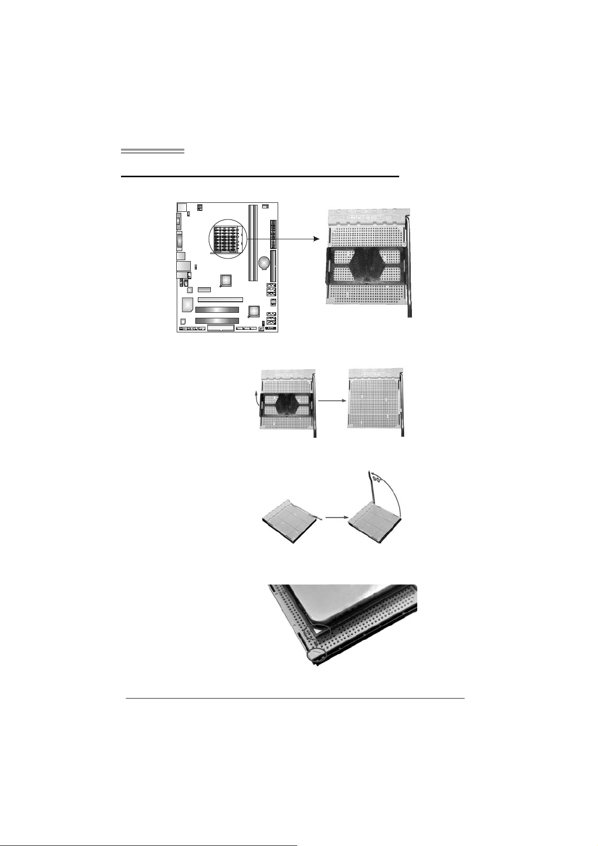
2.1 I
NSTALLING CENTRAL PROCESSING UNIT (CPU)
Step 1: Remove the socket protection cap.
Step 2: Pull the lever toward direction A from the socket and then raise the
lever up to a 90-degree angle.
Step 3: Look for the white triangle on socket, and the gold triangle on
CPU should point towards this white triangle. The CPU will fit only
in the correct orientation.
5
Page 8
Motherboard Manual
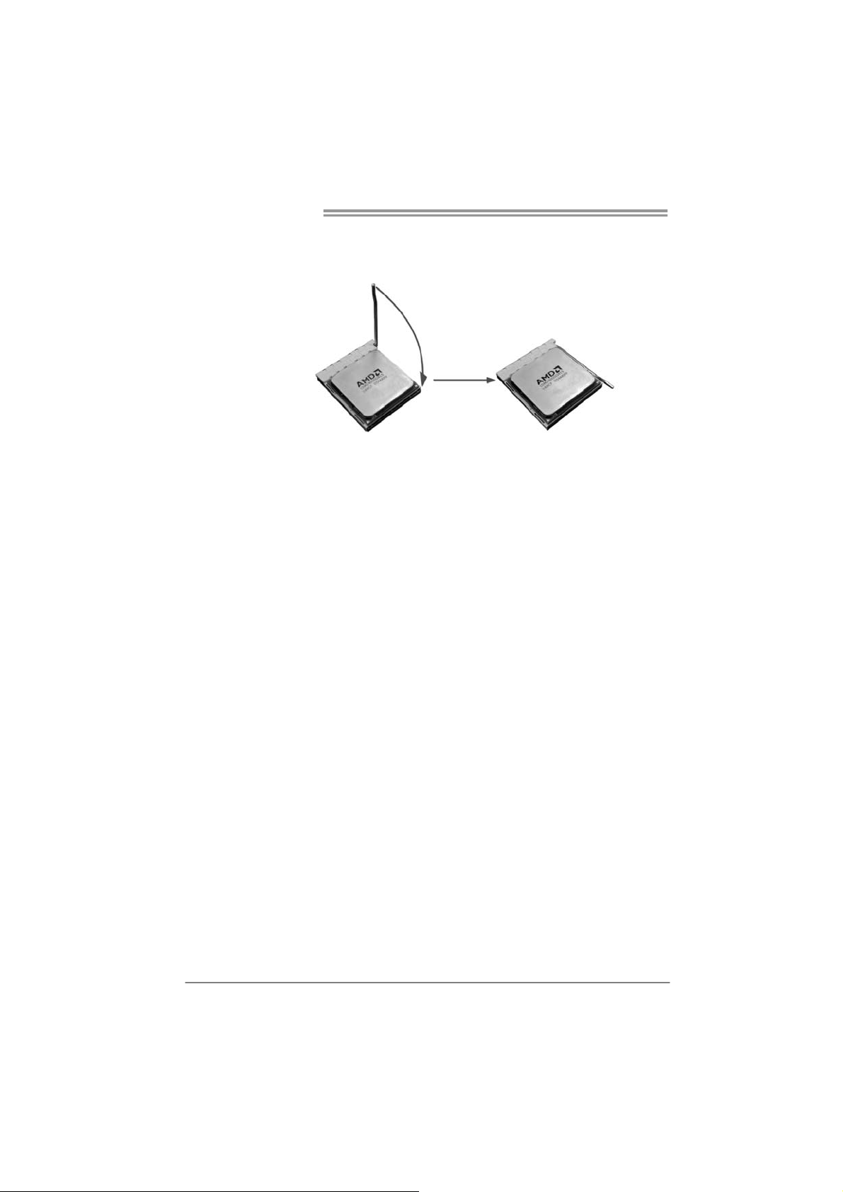
Step 4: Hold the CPU down firmly, and then close the lever toward direct
B to complete the installation.
Step 5: Put the CPU Fan on the CPU and buckle it. Connect the CPU
FAN power cable to the JCFAN1. This completes the installation.
Note: Please update the BIOS to the latest version while using AM2+ CPUs. Due to the latest CPU
transition, you may e ncounter the situation that the new system failed to boot while using new
AM2+ CPUs. In this case, please install one standard AM2 CPU to boot your system, and
update the latest BIOS from our website for AM2+ CPUs support.
6
Page 9
A780G M2+ SE/A780V M2+ SE/A760G M2+/A740G M2+ SE
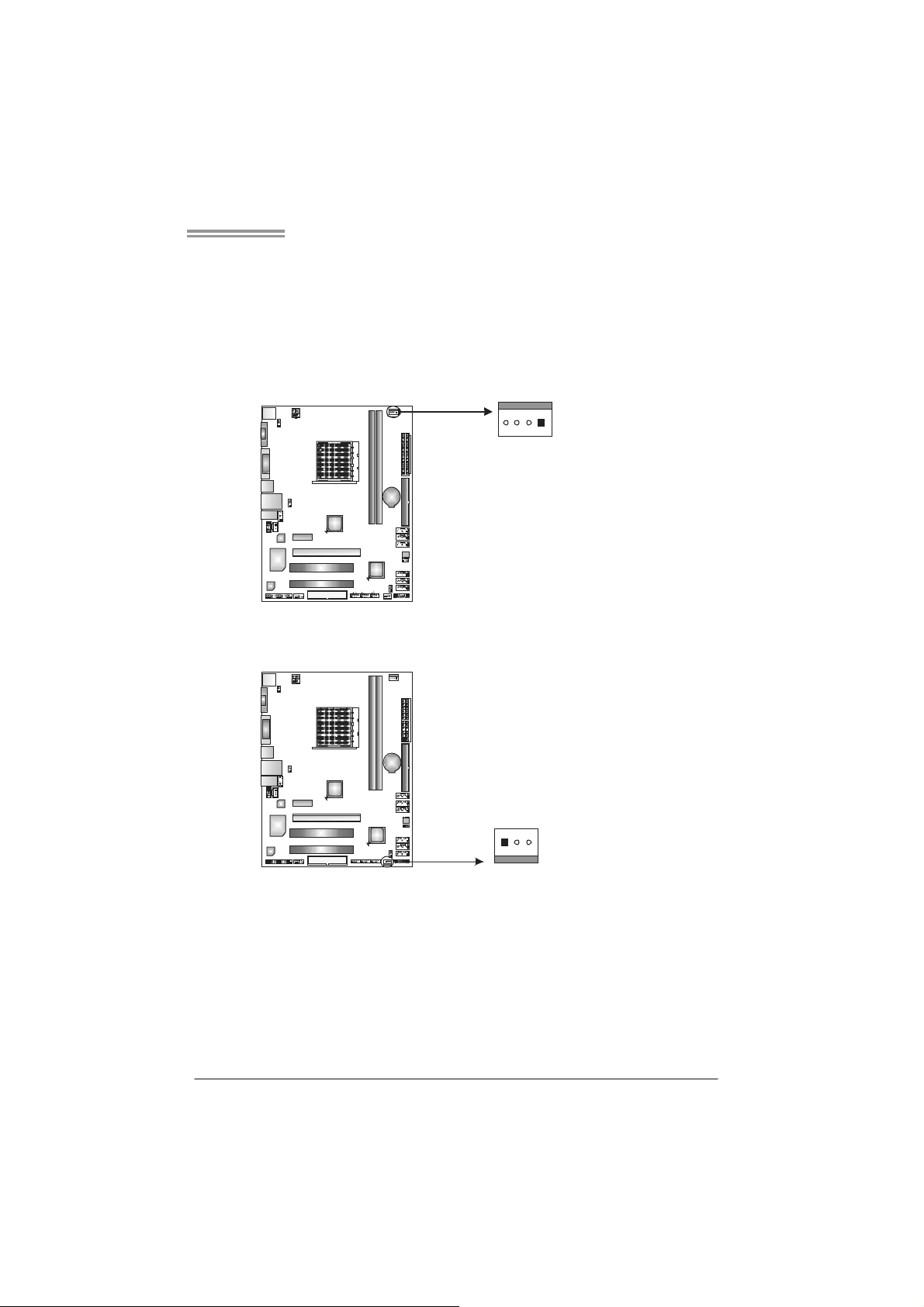
2.2 FAN HEADERS
These fan headers support cooling-fans built in the computer. The fan
cable and connector may be different according to the fan manufacturer.
Connect the fan cable to the connector while matching the black wire to
pin#1.
JCFAN1: CPU Fan Header
14
JSFAN1: System Fan Header
Pin
Assignment
1 Ground
2 +12V
3
FAN RPM r ate
sense
4 Smart Fan
Control (By Fan)
Pin
Assignment
1 Ground
2 +12V
3 FAN RPM rate
sense
13
Note:
The JCFAN1 supports 4-pin head connector. The JSFAN1 supports 3-pi n head
connector. When connecting with wires onto connectors, please note that the red wire is
the positive and should be connected to pin#2, and the black wire is Ground and should
be connected to GND.
7
Page 10
Motherboard Manual
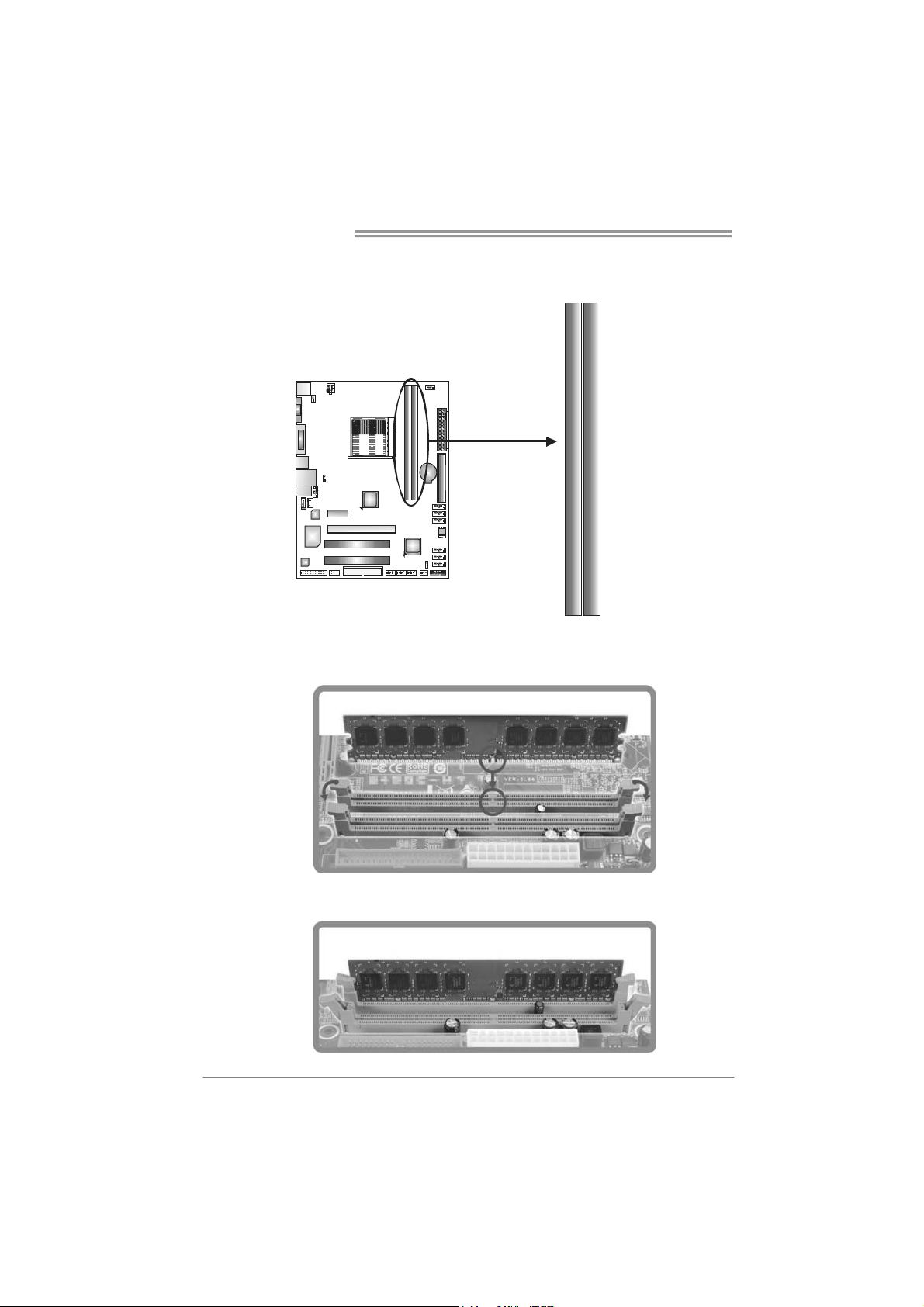
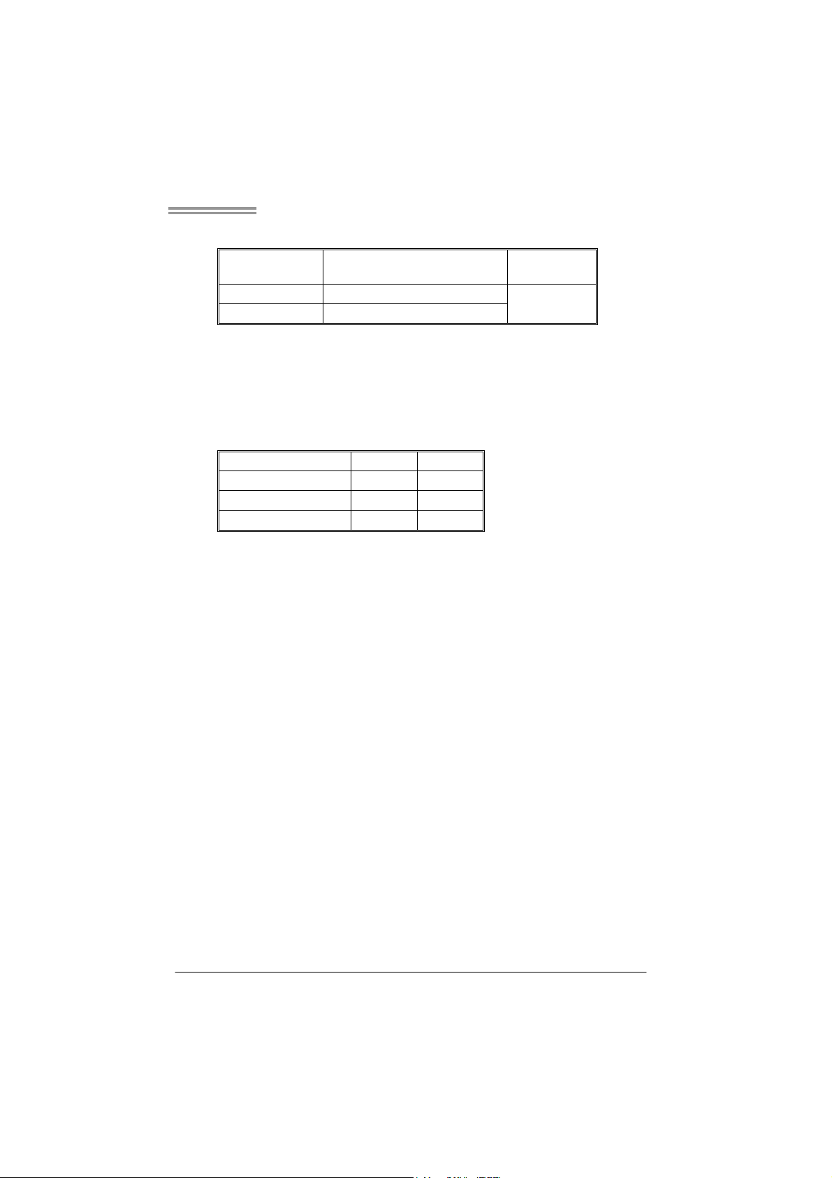
2.3 INSTALLING SYSTEM MEMORY
A. Memory Modules
DIMMB1
DIMMA1
1. Unlock a DIMM slot by pressing the retaining clips outward. Align a
DIMM on the slot such that the notch on the DIMM matches the
break on the Slot.
2. Insert the DIMM vertically and firmly into the slot until the retaining
chip snap back in place and the DIMM is properly seated.
8
Page 11
A780G M2+ SE/A780V M2+ SE/A760G M2+/A740G M2+ SE
B. Memory Capacity
DIMM Socket
Location
DIMMA1 256MB/512MB/1GB/2GB/4GB
DIMMB1 256MB/512MB/1GB/2GB/4GB
DDR2 Module
Total Mem o ry
Size
Max is 8GB.
C. Dual Channel Memory installation
To trigger the Dual Channel function of the motherboard, the memory module
must meet the following requirements:
Install memory module of the same density in pairs, shown in the following
table.
Dual Channel Status
Disabled X O
Disabled O X
Enabled O O
(O means memory installed, X means memory not installed.)
The DRAM bus width of the memory module must be the same (x8 or
x16)
DIMMA1
DIMMB1
9
Page 12
Motherboard Manual
3
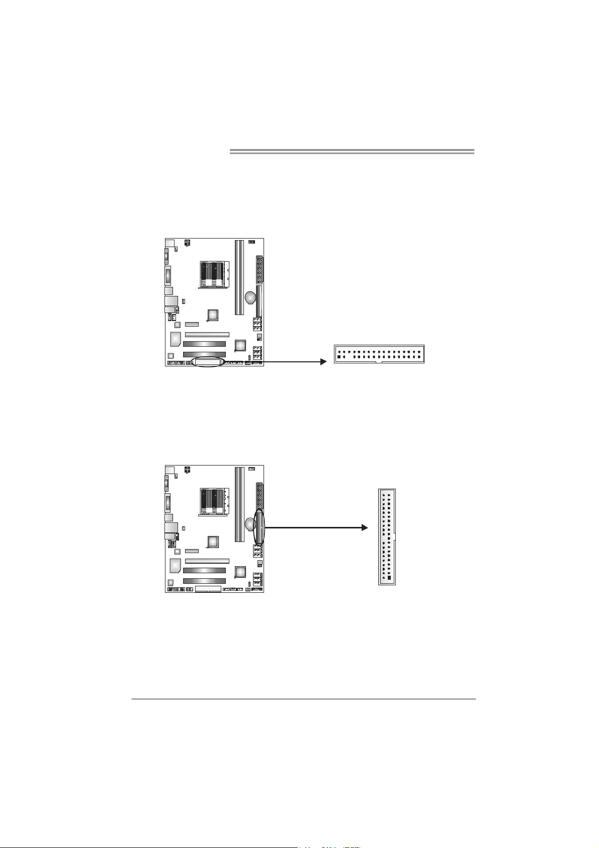
2.4 CONNECTORS AND SLOTS
FDD1: Floppy Disk Connector
The motherboard provides a standard floppy disk connector that supports 360K,
720K, 1.2M, 1.44M and 2.88M floppy disk types. This connector supports the
provided floppy drive ribbon cable.
234
IDE1: IDE/ATAPI Connector
The motherboard has a 32-bit Enhanced PCI IDE Controller that provides PIO
Mode 0~4, Bus Master, and Ultra DMA 33/66/100/133 functionality.
The IDE connector can connect a master and a slave drive, so you can connect
up to two drives.
13
21
3940
10
Page 13
A780G M2+ SE/A780V M2+ SE/A760G M2+/A740G M2+ SE
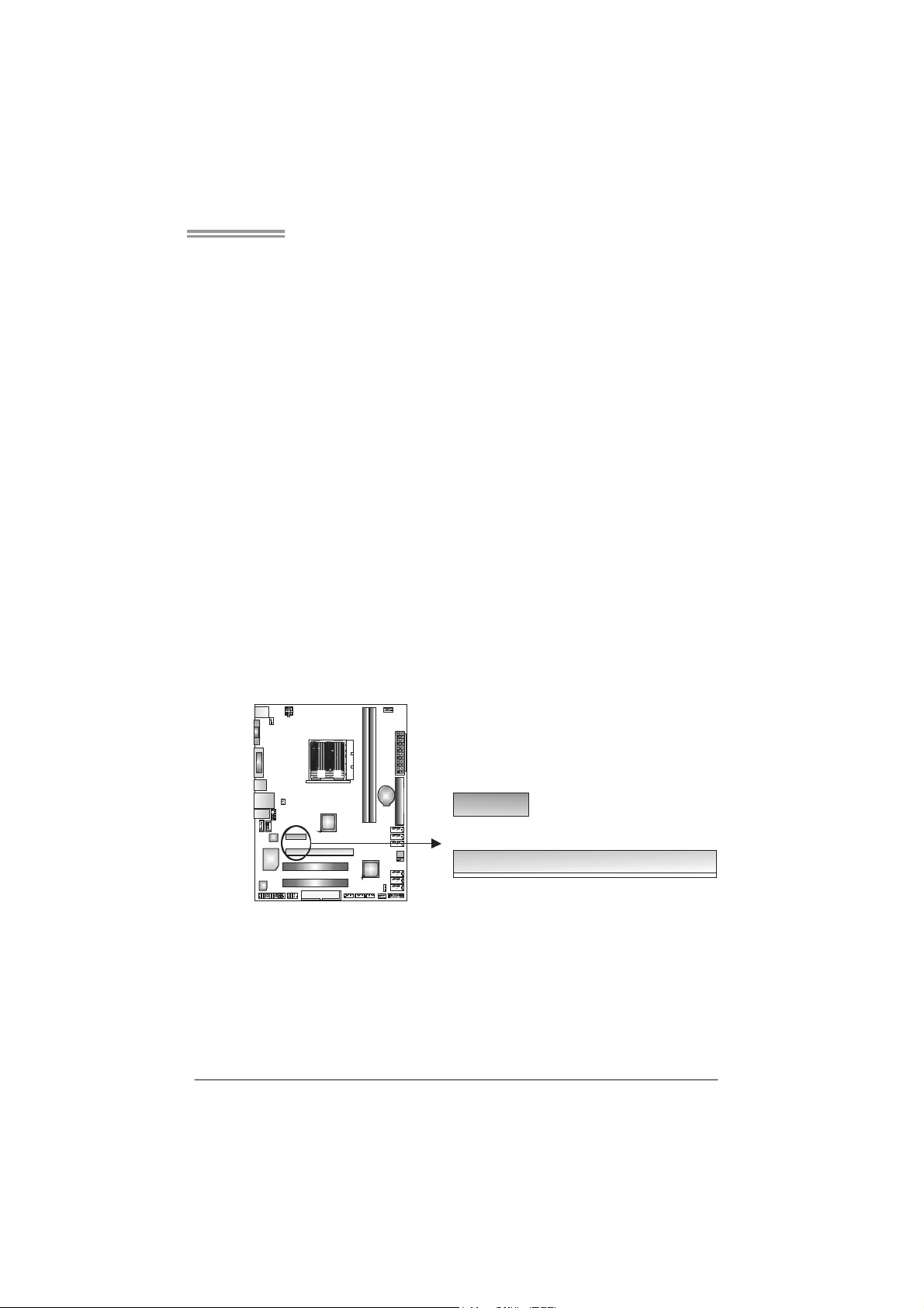
PEX16_1: PCI-Express Gen2 x16 Slot (for A780G M2+ SE/A780V
M2+ SE/A760G M2+)
- PCI-Express 2.0 compliant.
- Maximum theoretical realized bandwidth of 8GB/s simultaneously per
direction, for an aggregate of 16GB/s totally.
PEX1_1: PCI-Express Gen2 x1 Slot (for A780G M2+ SE/A780V M2+
SE/A760G M2+)
- PCI-Express 2.0 compliant.
- Data transfer bandwidth up to 500MB/s per direction; 1GB/s in total.
- PCI-Express supports a raw bit-rate of 5.0Gb/s on the data pins.
- 2X bandwidth over the PCI-Express 1.1 architecture.
PEX16_1: PCI-Express x16 Slot (for A740G M2+ SE)
- PCI-Express 1.1 compliant.
- Maximum theoretical realized bandwidth of 4GB/s simultaneously per
direction, for an aggregate of 8GB/s totally.
PEX1_1: PCI-Express x1 Slot (for A740G M2+ SE)
- PCI-Express 1.1 compliant.
- Data transfer bandwidth up to 250MB/s per direction; 500MB/s in total.
- PCI-Express supports a raw bit-rate of 2.5GB/s on the data pins.
- 2X bandwidth over the traditional PCI architecture.
PE X1_1
PEX16_1
11
Page 14
Motherboard Manual
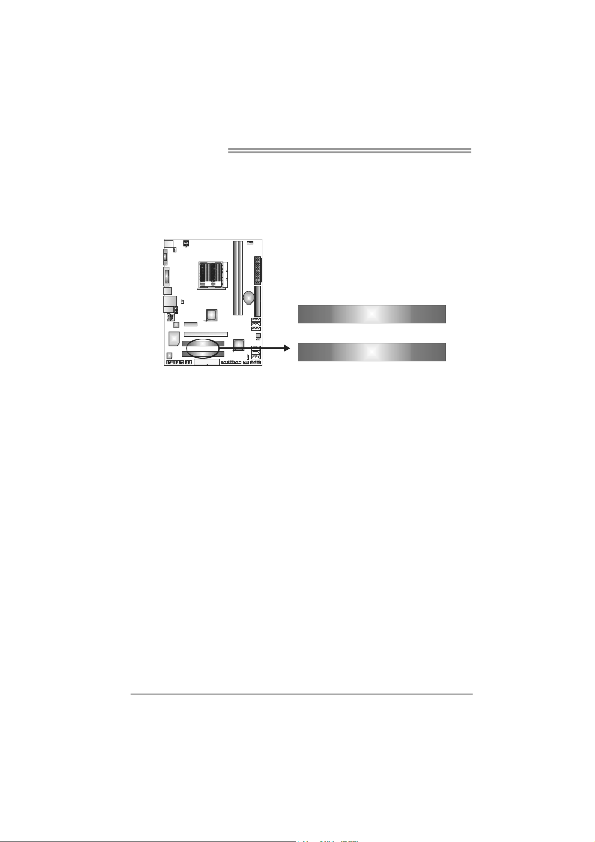
PCI1~PCI2: Peripheral Component Interconnect Slots
This motherboard is equipped with 2 standard PCI slots. PCI stands for
Peripheral Component Interconnect, and it is a bus standard for expansion
cards. This PCI slot is designated as 32 bits.
PCI1
PCI2
12
Page 15
A780G M2+ SE/A780V M2+ SE/A760G M2+/A740G M2+ SE
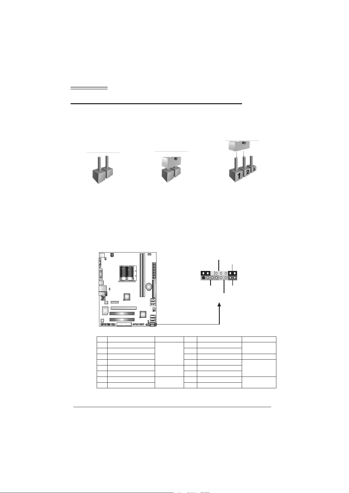
CHAPTER 3: HEADERS & JUMPERS SETUP
3.1 H
OW TO SETUP JUMPERS
The illustration shows how to set up jumpers. When the jumper cap is
placed on pins, the jumper is “close”, if not, that means the jumper is
“open”.
Pin opened Pin closed Pin1-2 closed
3.2 D
JPANEL1: Front Panel Header
ETAIL SETTINGS
This 16-pin connector includes Power-on, Reset, HDD LED, Power LED, and
speaker connection. It allows user to connect the PC case’s front panel switch
functions.
PWR_LED
On/Off
-
9
1
++
SPK
HL ED
16
8
-
+
RST
Pin Assignment Function Pin Assignment Function
1 +5V 9 N/A
2 N/A 10 N/A
3 N/ A 1 1 N/ A N/ A
4 Speaker
5 HDD LED (+) 13 Power LED (+)
6 HDD LED (-)
7 Ground 15 Power button
8 Reset control
Speaker
Connector
Hard drive
LED
Reset button
12 Power LED (+)
14 Power LED (-)
16 Ground
N/A
Power LED
Power-on button
13
Page 16
Motherboard Manual
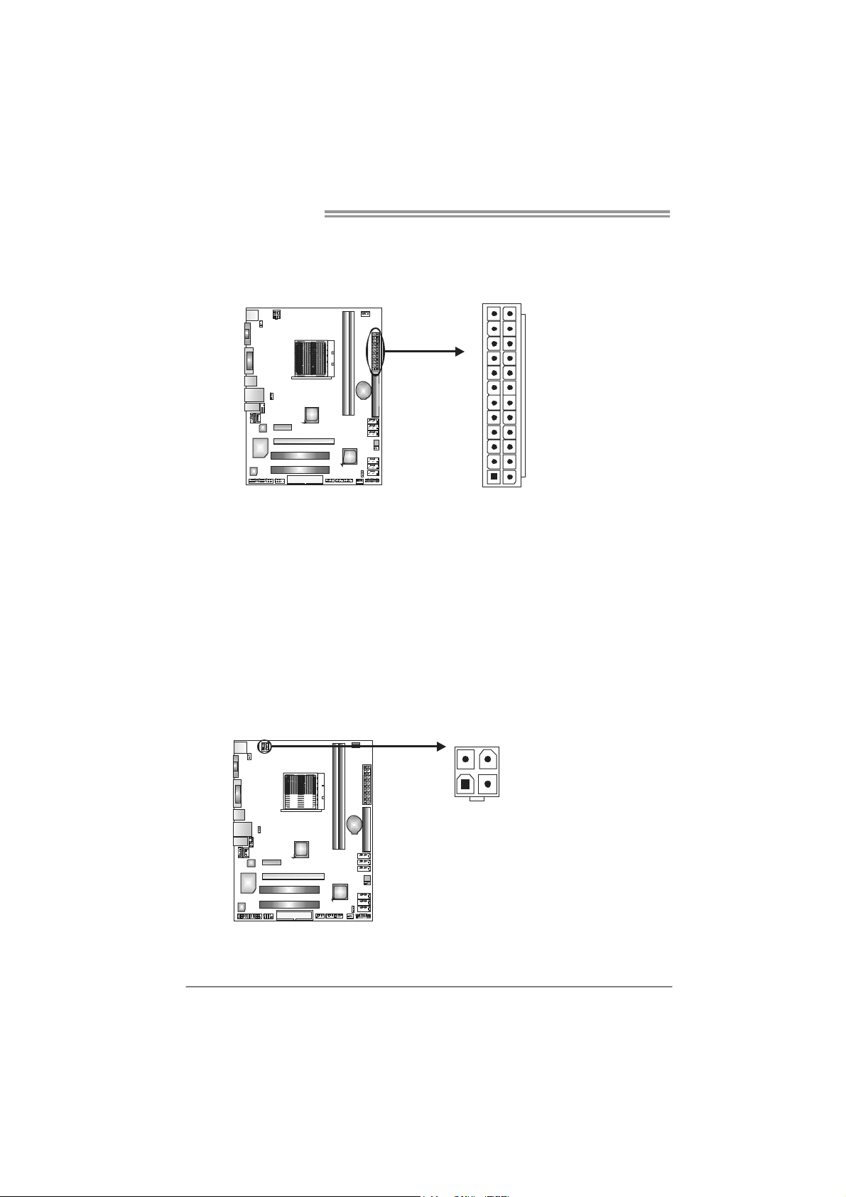
JATXPW R1: AT X Power Source Connector
This connector allows user to connect 24-pin power connector on the ATX
power supply.
12
1
Pin Assignment Pin Assignm ent
13 +3.3V 1 +3.3V
14 -12V 2 +3.3V
15 Ground 3 Ground
16 PS_ON 4 +5V
17 Ground 5 Ground
18 Ground 6 +5V
19 Ground 7 Ground
20 NC 8 PW_OK
21 +5V 9 Standby Voltage+5V
22 +5V 10 +12V
23 +5V 11 +12V
24 Ground 12 +3.3V
24
13
JATXPW R2: AT X Power Source Connector
By connecting this connector, it will provide +12V to CPU power circuit.
34
12
Pin
Assignment
1 +12V
2 +12V
3 Ground
4 Ground
14
Note:
Before power on the s ystem, please make sure that both JATXPWR1 and JATXPWR2
connectors have been plugged-in.
Page 17

A780G M2+ SE/A780V M2+ SE/A760G M2+/A740G M2+ SE
JUSB2/JUSB3/JUSB4: Headers for USB 2.0 Ports at Front Panel
This header allows user to connect additional USB cable on the PC front panel,
and also can be connected with internal USB devices, like USB card reader.
Assignment
Pin
1 +5V (fused)
2 +5V (fused)
3 USB4 USB5 USB+
6 USB+
7 Ground
JUSB4 JUSB3 JUSB2
210
8 Ground
9 NC
10 Key
19
SATA1~SATA6: Serial ATA Connectors
The motherboard has a PCI to SATA Controller with 6 channels SATA interface,
it satisfies the SATA 2.0 spec and with transfer rate of 3.0Gb/s.
SAT A6
SAT A5
SAT A4
SAT A3
SAT A2
SAT A1
7
14
Pin
Assignment
1 Ground
2 TX+
3 TX4 Ground
5 RX6 RX+
7 Ground
15
Page 18

Motherboard Manual
JSPDIF_OUT1: Digital Audio-out Connector
This connector allows user to connect the PCI bracket SPDIF output header.
JAUDIOF1: Front Panel Audio Header
This header allows user to connect the front audio output cable with the PC front
panel. This header allows only HD audio front panel connector; AC’97 connector
is not acceptable.
10
Pin
Assignment
1 +5V
2 SPDIF_OUT
1
3 Ground
3
Pin Assignment
1 Mic Left in
2 Ground
3 Mic Right in
4 GPIO
9
1
2
5 Right line in
6 Jack Sense
7 Front Sense
8 Key
9 Left line in
10 Jack Sense
16
Page 19

A780G M2+ SE/A780V M2+ SE/A760G M2+/A740G M2+ SE
JCDIN1: CD-ROM Audio-in Connector
This connector allows user to connect the audio source from the variaty devices,
like CD-ROM, DVD-ROM, PCI sound card, PCI TV turner card etc.
Assignment
Pin
1 Left Channel Input
2 Ground
3 Ground
1
4 Right Channel Input
4
JCMOS1: Clear CMOS Header
By placing the jumper on pin2-3, it allows user to restore the BIOS safe setting
and the CMOS data, please carefully follow the procedures to avoid damaging
the motherboard.
13
Pin 1-2 Close:
Normal Operation (default).
13
13
Pin 2-3 Close:
Clear CMOS data.
※ Clear CMOS Procedures:
1. Remove AC power line.
2. Set the jumper to “Pin 2-3 close”.
3. Wait for five seconds.
4. Set the jumper to “Pin 1-2 close”.
5. Power on the AC.
6. Reset your desired password or clear the CMOS data.
17
Page 20

Motherboard Manual
JPRNT1: Printer Port Connector
This header allows you to connector printer on the PC.
Pin Assignment Pin Assignment
1 -Strobe 14 Ground
2 -ALF 15 Data 6
3 Data 0 16 Ground
4 -Error 17 Data 7
5 Data 1 18 Ground
6 -Init 19 -ACK
7 Data 2 20 Ground
8 -Scltin 21 Busy
9 Data 3 22 Ground
10 Ground 23 PE
11 Data 4 24 Ground
12 Ground 25 SCLT
13 Data 5 26 Key
2
125
JCOM1: Serial port Connector
The motherboard has a Serial Port Connector for connecting RS-232 Port.
18
210
19
Pin
Assignment
1 Carrier detect
2 Received data
3 Transmitted data
4 Data terminal ready
5 Signal ground
6 Data set ready
7 Request to send
8 Clear to send
9 Ring indicator
10 NC
Page 21

A780G M2+ SE/A780V M2+ SE/A760G M2+/A740G M2+ SE
JUSBV1/JUSBV2: Power Source Headers for USB Ports
Pin 1-2 Close:
JUSBV1: +5V for USB ports at JUSB1/JUSBLAN1.
JUSBV2: +5V for USB ports at front panel (JUSB2/JUSB3/JUSB4).
Pin 2-3 Close:
JUSBV1: +5V STB for USB ports at JUSB1/JUSBLAN1.
JUSBV2: +5V STB for USB ports at front panel (JUSB2/JUSB3/JUSB4).
Pin 1-2 close
JUSBV1
3
1
3
1
JUSBV2
Pin 2-3 close
3
1
JKBV1: Power Source Header for PS/2 Keyboard and Mouse
3
1
+5V for PS/2 keyboard and
mouse.
+5V STB for PS/2
keyboard and mouse.
3
1
Pin 1-2 close
3
1
Pin 2-3 close
19
Page 22

Motherboard Manual
CHAPTER 4: HYBRID CROSSFIREX FUNCTION (FOR
A780G M2+ SE/A780V M2+ SE/A760G M2+)
4.1 H
YBRID CROSSFIREX REQUIREMENTS
Only Windows Vista supports Hybrid CrossFireX function.
A graphics card with Radeon HD3450/HD3470 GPU.
The graphics card driver should support Hybrid CrossFireX technology.
The power supply unit must provide at least the minimum power required by
the system, or the system will be unstable. A power supply above 450W is
recommended under Hybrid CrossFireX mode.
4.2 HYBRID CROSSFIREX INSTALLATION
Step 1: Insert the Hybrid CrossFireX-Ready graphics card into PEX16_1.
PEX16_1
R a de on H D 3 4 5 0
R a de on H D 3 4 7 0
20
Notice: Make sure the card is seated into slot completely.
Step 2: In the graphics card configuration program, choose “Hybrid
CrossFireX” function. Installation completes.
NOTE
For more detail information of Hybrid CrossFireX function, please visit following
web-sites:
http://game.amd.com/us-en/crossfirex_hybrid.aspx
http://ati.amd.com/technology/hybridgraphics/index.html
Page 23

A780G M2+ SE/A780V M2+ SE/A760G M2+/A740G M2+ SE
CHAPTER 5: RAID FUNCTIONS
5.1 O
Supports Windows XP Home/Professional Edition, and Windows Vista 32 / Vista 64.
PERATING SYSTEM
5.2 RAID ARRAYS
RAID supports the following types of RAID arrays:
RAID 0: RAID 0 defines a disk striping scheme that improves disk read and write times for
many applications.
RAID 1: RAID 1 defines techniques for mirroring data.
RAID 1+0: RAID 1+0 combines the techniques used in RAID 0 and RAID 1.
5.3 HOW RAID WORKS
RAID 0:
The controller “stripes” data across multiple drives in a RAID 0 array system. It breaks
up a large file into smaller blocks and performs disk reads and writes across multiple
drives in parallel. The size of each block is determined by the stripe size parameter,
which you set during the creation of the RAID set based on the system environment.
This technique reduces overall disk access time and offers high bandwidth.
Features and Benefits
- Drives: Minimum 2, and maximum is up to 6 or 8. Depending on the
platform.
- Uses: Intended for non-critical data requiring high data throughput, or any
environment that does not require fault tolerance.
- Benefits: provides increased data throughput, especially for large files.
No capacity loss penalty for parity.
- Drawbacks: Does not deliver any fault tolerance. If any drive in the array
fails, all data is lost.
- Fault Tolerance: No.
Block 1
Block 3
Block 5
Block 2
Block 4
Block 6
21
Page 24

Motherboard Manual
RAID 1:
Every read and write is actually carried out in parallel across 2 disk drives in a RAID 1
array system. The mirrored (backup) copy of the data can reside on the same disk or on
a second redundant drive in the array. RAID 1 provides a hot-standby copy of data if
the active volume or drive is corrupted or becomes unavailable because of a hardware
failure.
RAID techniques can be applied for high-availability solutions, or as a form of
automatic backup that eliminates tedious manual backups to more expensive and less
reliable media.
Features and Benefits
- Drives: Minimum 2, and maximum is 2.
- Uses: RAID 1 is ideal for small databases or any other application that
requires fault tolerance and minimal capacity.
- Benefits: Provides 100% data redundancy. Should one drive fail, the
controller switches to the other drive.
- Drawbacks: Requires 2 drives for the storage space of one drive.
Performance is impaired during drive rebuilds.
- Fault Tolerance: Yes.
22
Block 1
Block 2
Block 3
Block 1
Block 2
Block 3
Page 25

A780G M2+ SE/A780V M2+ SE/A760G M2+/A740G M2+ SE
RAID 1+0:
RAID 1 drives can be stripped using RAID 0 techniques. Resulting in a RAID 1+0
solution for improved resiliency, performance and rebuild performance.
Features and Benefits
- Drives: Minimum 4, and maximum is 6 or 8, depending on the platform.
- Benefits: Optimizes for both fault tolerance and performance, allowing for
automatic redundancy. May be simultaneously used with other RAID
levels in an array, and allows for spare disks.
- Drawbacks: Requires twice the available disk space for data redundancy,
the same as RAID level 1.
- Fault Tolerance: Yes.
Block 1
Block 3
Block 5
Block 1
Block 3
Block 5
Block 2
Block 4
Block 6
Block 2
Block 4
Block 6
23
Page 26

Motherboard Manual
CHAPTER 6: USEFUL HELP
6.1 D
RIVER INSTALLATION NOTE
After you installed your operating system, please insert the Fully Setup
Driver CD into your optical drive and install the driver for better system
performance.
You will see the following window after you insert the CD
The setup guide will auto detect your motherboard and operating system.
Note:
If this window didn’t show up after you insert the Drive r CD, please use file browser to
locate and execute the file SETUP.EXE under your optical drive.
A. Driver Installation
To install the driver, please click on the Driver icon. The setup guide will
list the compatible driver for your motherboard and operating system.
Click on each device driver to launch the installation program.
B. Software Installation
To install the software, please click on the Software icon. The setup guide
will list the software available for your system, click on each software title
to launch the installation program.
C. Manual
Aside from the paperback manual, we also provide manual in the Driver
CD. Click on the Manual icon to browse for available manual.
Note:
You will need Acrobat Reader to open the manual file. Please download the latest version
of Acrobat Reader software from
http://www.adobe.com/products/a crobat/readstep2.html
24
Page 27

A780G M2+ SE/A780V M2+ SE/A760G M2+/A740G M2+ SE
e
6.2 SOFTWARE
Installing Software
1. Insert the Setup CD to the optical drive. The drivers installation program
would appear if the Autorun function has been enabled.
2. Select Software Installation, and then click on the respective software
title.
3. Follow the on-screen instructions to complete the installation.
Launching Software
After the installation process, you will see the software icon “eHOT Line” /
“BIOS Update” appears on the desktop. Double-click the icon to launch the
utility.
eHot-Line (Optional)
eHot-Line is a convenient utility that helps you to contact with our
Tech-Support system. This utility will collect the system information which is
useful for analyzing the problem you may have encountered, and then send
these information to our tech-support department to help you fix the problem.
Before you use this utility, please set Outlook E xpress as your default e- mail client applica tion program.
re pr es ent s im porta nt
*
information that you
must provide. Without
this information, y ou may
not be able to send out
the mail.
This bl ock will show
the information which
would be collected in
the m ail .
Describe conditi on
*
of your system.
Select your area or
*
the area cl ose to you.
Provide the e-mail
address that you would
like to send the copy to.
Pr ovid e the na me of
*
the memory module
manufacturer.
Provide the name of
th e powe r su ppl y
manufacturer and the
model no.
Se nd th e mai l out .
Sav e thes e in for ma tion t o a .txt fil
Exit this dialog.
25
Page 28

Motherboard Manual
After filling up this information, click “Send”
to send the mail out. A warning dialog would
appear asking for your confirmation; click
“Send” to confirm or “Do Not Send” to cancel.
If you want to save this information to a .txt file, click “Save As…” and then you
will see a saving dialog appears asking you to enter file name.
Enter the file name and then click
“Save”. Your system information
will be saved to a .txt file.
26
Open the saved .txt file, you will see
your system information including
motherboard/BIOS/CPU/video/
device/OS information. This
information is also concluded in the
sent mail.
We will not share customer’s data with any other third parties,
so please feel free to provide your system information while using
eHot-Line service.
If you are not using Outlook Express as your default e-mail client
application, you may need to save the system information to a .txt file
and send the file to our tech support with other e-mail application.
Go to the following web
http://www.biostar.com.tw/app/en-us/about/contact.php for getting
our contact information.
Page 29

A780G M2+ SE/A780V M2+ SE/A760G M2+/A740G M2+ SE
BIOS Update
BIOS Update is a convenient utility which allows you to update your
motherboard BIOS under Windows system.
AWARD BIOS AMI BIOS
Clear CMOS function
(Only for AWARD BIOS)
Show c urrent BIOS information
Save cur rent B IOS
to a .bin file
Update BIOS
with a BIOS file
<Backup BIOS>
Once click on this button, the saving
dialog will show. Choose the
position to save file a nd enter file
name. (We recommend that the file
name should be English/number
and no longer than 7 characters.)
Then click Save.
After the saving process, finish
dialog will show. Click on OK to
complete the BIOS Backup
procedure.
27
Page 30

Motherboard Manual
<Update BIOS>
Before doing this, please download the proper BIOS file from the website.
For AWARD BIOS, update BIOS procedure
should be run with Clear CMOS function, so
please check on Clear CMOS first.
Then click Update BIOS button, a
dialog will show for asking you backup
current BIOS. Click Yes for BIOS
backup and refer to the Backup BIOS
procedure; or click No to skip this
procedure.
After the BIOS Backup procedure, the
open dialog will show for requesting the
BIOS file which is going to be updated.
Please choose the proper BIOS file for
updating, then click on Open.
The utility will update BIOS with the
proper BIOS file, and this process may
take minutes. Please do not open any
other applications during this process.
After the BIOS Update process, click on
OK to restart the system.
While the system boots up and the full screen logo shows, press <Delete>
key to enter BIOS setup.
In the BIOS setup, use the Load Optimized Defaults function and then Save and
Exit Setup to exit BIOS setup. BIOS Update is completed.
All the informa tion and content above about the software are subject to be changed
witho ut notice. For better performance, the software is being continuously updated.
The information and pictures described above are for your reference only. The actual
information and settings on board may be slightly differe nt from this manual.
28
Page 31

A780G M2+ SE/A780V M2+ SE/A760G M2+/A740G M2+ SE
6.3 EXTRA INFORMATION
CPU Overheated
If the system shutdown automatically after power on system for
seconds, that means the CPU protection function has been activated.
When the CPU is over heated, the motherboard will shutdow n
automatically to avoid a damage of the CPU, and the system may not
power on again.
In this case, please double check:
1. The CPU cooler surface is placed evenly with the CPU surface.
2. CPU fan is rotated normally.
3. CPU fan speed is fulfilling with the CPU speed.
After confirmed, please follow steps below to relief the CPU protection
function.
1. Remove the power cord from power supply for seconds.
2. Wait for seconds.
3. Plug in the power cord and boot up the system.
Or you can:
1. Clear the CMOS data.
(See “Close CMOS Header: JCMOS1” section)
2. Wait for seconds.
3. Power on the system again.
29
Page 32

Motherboard Manual
BIO-Flasher
BIO-Flasher is a BIOS flashing utility providing you an easy and simple way to
update your BIOS via USB pen drive or floppy disk.
The BIO-Flasher is built in the BIOS chip. To enter the utility, press <F12>
during the Power-On Self Tests (POST) procedure while booting up.
Updating BIOS with BIO-Flasher
1. Go to the website to download the latest BIOS file for the motherboard.
2. Then, save the BIOS file into a USB pen drive or a floppy disk.
3. Insert the USB pen drive or the floppy disk that contains the BIOS file to the
USB port or the floppy disk drive.
4. Power on or reset the computer and then
press <F12> during the POST process.
A select dialog as the picture on the right
appears.
Select the device contains the BIOS file and
press <Enter> to enter the utility.
30
5. The utility will show the BIOS
files and their respective
information. Select the proper
BIOS file and press <Enter>
then <Y> to perform the BIOS
update process.
6. After the update process, the utility will ask you to reboot the system.
Press <Y> to proceed. BIOS update completes.
z This utility only allows storage device with FAT32/16 format and single
parti tion.
z Shutting down or resetting the system while updating the BIOS will lead to
syste m boot failure.
Page 33

A780G M2+ SE/A780V M2+ SE/A760G M2+/A740G M2+ SE
6.4 AMI BIOS BEEP CODE
Boot Block Beep Codes
Number of Beeps Description
1 No media present. (Insert diskette in floppy drive A:)
2
3 Insert next diskette if multiple diskettes are used for recovery
4 Flash Programming successful
5 File read error
7 No Flash EPROM detected
10 Flash Erase error
11 Flash Program error
12 “AMIBOOT.ROM” file size error
13
POST BIOS Beep Codes
Number of Beeps Description
1 Memory refresh timer error
3 Base memory read/write test error
6 Keyboard controller BAT command failed
7 General exception error (processor exception interrupt error)
8 Display memory error (system video adapter)
“AMIBOOT.ROM” file not found in root directory of diskette in
A:
BIOS ROM image mismatch (file layout does not match
image present in flash device)
Troubleshooting POST BIOS Beep Codes
Number of Beeps Troubleshooting Action
1, 3 Reseat the memory, or replace with known good modules.
Fatal error indicating a serious problem with the system.
Consult your system manufacturer. Before declaring the
motherboard beyond all hope, eliminate the possibility of
interference by a malfunctioning add-in card. Remove all
expansion cards except the video adapter.
6, 7
8
z If beep codes are generated when all other expansion
cards are absent, consult your system manufacturer’s
technical support.
z If beep codes are not generated when all other expansion
cards are absent, one of the add-in cards is causing the
malfunction. Insert the cards back into the system one at a
time until the problem happens again. This will reveal the
malfunctioning card.
If the system video adapter is an add-in card, replace or
reseat the
video adapter. If the video adapter is an integrated part of the
system board, the board may be faulty.
31
Page 34

Motherboard Manual
6.5 TROUBLESHOOTING
Probable Solution
1. No power to the system at all
Power light don’t illuminate, fan
inside power supply does not turn
on.
2. Indicator light on keyboard does
not turn on.
System inoperative. Keyboard lights
are on, power indicator lights are lit,
and hard drive is spinning.
System does not boot from hard disk
drive, can be booted from optical drive.
System only boots from optical drive.
Hard disk can be read and applications
can be used but booting from hard disk
is impossible.
Screen message says “Invalid
Configuration” or “CMOS Failure.”
Cannot boot system after installing
second hard drive.
1. Make sure power cable is
securely plugged in.
2. Replace cable.
3. Contact technical support.
Using even pressure on both ends of
the DIMM, press down firmly until the
module snaps into place.
1. Check cable running from disk to
disk controller board. Make sure
both ends are securely plugged
in; check the drive type in the
standard CMOS setup.
2. Backing up the hard drive is
extremely important. All hard
disks are capable of breaking
down at any time.
1. Back up data and applications
files.
2. Reformat the hard drive.
Re-install applications and data
using backup disks.
Review system’s equipment. Make sure
correct information is in setup.
1. Set master/slave jumpers
correctly.
2. Run SETUP program and select
correct drive types. Call the drive
manufacturers for compatibility
with other drives.
32
Page 35

A780G M2+ SE/A780V M2+ SE/A760G M2+/A740G M2+ SE
This page is intentionally left blank.
33
Page 36

Motherboard Manual
APPENDIX: SPEC IN OTHER LANGUAGES
G
ERMAN
CPU
FSB
Chipsatz
Super E/A
Arbeitsspeiche
r
Grafik
IDE
SATA
LAN
A7 80 G M2+ SE/A780V M2 + SE/ A760G M2+
Sockel AM2+ / AM2
AMD Athlon 64 / Athlon 64 FX / Athlon 64 X2 /
Sempro n / Pheno m Proz es so ren
Die AMD 64-Architektur unterstützt eine 32-Bit- und
64-Bit-Datenverarbeitung
Unterstützt Hyper Transport 3.0 und PowerNow
Athlon Max. Power:125W ; Phenom Max. Power:95W
Unterstützt HyperTransport 3.0 mit einer Bandbreite
von bis zu 5.2 GT/s
AMD 780G (A780G M2+ SE)
AMD 780V (A780V M2+ SE )
AMD 760G (A760G M2+)
AMD SB700 (A780G M2 + SE & A780V M2+ SE)
AMD SB710 (A760G M2+)
ITE8718F
Bietet die häufig verwendeten alten Super
E/A-Funktionen.
Low Pin Count-Schnittstelle
Umg ebungs kontrolle,
Hardware-Überwachung
"Smart Guardian"-Funktion von ITE
DDR2 DIMM-Steckplätze x 2
Max. 8GB Arbeitsspeicher
Jeder DIMM unterstützt 256MB/512MB/
1GB/2GB/4GB DDR2.
Dual-Kanal DDR2 Speichermodul
Unt erstützt DDR2 533 / 667 / 800
Unterstützt DDR2 1066 (for AM2+ CPU only)
reg istrierte DIMMs. ECC DIMMs werden nicht
unterstützt.
ATI Radeon HD 32 00 (A780 G M2+ SE)
ATI Rad eon 31 00 (A7 80V M2 + SE)
ATI Rad eon 30 00 (A7 60G M2 +)
Max. 512MB gemeinsam benutzter Videospeicher
Unt erstützt DX10/HDCP (A 780G M2+ SE & A780V
M2+ SE nur)
Unterstützt Hybrid CrossFireX
Unterstützt UVD (for A780G M2+ SE only)
Int egrierter IDE-Controller
Ultra DMA 33 / 66 / 100 / 133 Bus Master-Modus
Unterstützt PIO-Modus 0~4,
Int egriert er Serial ATA-Contro ller
Datentrans ferrat e bis z u 3 G b/s
Konform mit der SATA-Spezifikation Vers io n 2.0.
Realtek RTL 8111C (A780G M2+ SE & A760G M2+)
Realtek RTL 8102EL (A780V M2+ SE)
Sockel AM2+ / AM2
AMD Athlon 64 / Athlon 64 FX / Athlon 64 X2 /
Sempro n / Pheno m Proz es so ren
Die AMD 64-Architektur unterstützt eine 32-Bit- und
64-Bit-Datenverarbeitung
Unterstützt Hyper Transport 2.0 und PowerNow
Athlon Max. Power:125W ; Phenom Max. Power:95W
Unterstützt HyperTransport 2.0 mit einer Bandbreite
von bis zu 2.0 GT/s
AMD 740G
AMD SB700
ITE8718F
Bietet die häufig verwendeten alten Super
E/A-Funktionen.
Low Pin Count-Schnittstelle
Umg ebungs kontrolle,
Hardware-Überwachung
"Smart Guardian"-Funktion von ITE
DDR2 DIMM-Steckplätze x 2
Max. 8GB Arbeitsspeicher
Jeder DIMM unterstützt 256MB/512MB/
1GB/2GB/4GB DDR2.
Dual-Kanal DDR2 Speichermodul
Unt erstützt DDR2 533 / 667 / 800
Unterstützt DDR2 1066 (for AM2+ CPU only)
reg istrierte DIMMs. ECC DIMMs werden nicht
unterstützt.
ATI Rad eon 2100
Max. 512MB gemeinsam benutzter Videospeicher
Unterstützt HDCP
Int egrierter IDE-Controller
Ultra DMA 33 / 66 / 100 / 133 Bus Master-Modus
Unterstützt PIO-Modus 0~4,
Int egriert er Serial ATA-Contro ller
Datentrans ferrat e bis z u 3 G b/s
Konform mit der SATA-Spezifikation Vers io n 2.0.
Realtek RTL 8102EL
10 / 100 Mb /s Auto- Negot iation
A740G M2+ SE
34
Page 37

A780G M2+ SE/A780V M2+ SE/A760G M2+/A740G M2+ SE
A7 80 G M2+ SE/A780V M2 + SE/ A760G M2+
10 / 100 /1000 Mb/s Auto-Negotiation (A780G M2+
SE & A760G M2+)
10 / 100 Mb /s Auto- Negot iation (A780V M2+ SE)
Halb-/ Vollduplex-Funktion
HD
Audio-Unterst
ützung
Steckplätze
Onboard-A nsc
hluss
Rückseiten-E/
A
Platinengröße 200 mm (B) X 244 mm (L) 200 mm (B) X 244 mm (L)
Sonderfunktio
nen
OS- Unterstütz
ung
ALC662
5.1-Kanal-Audioausgabe
Unterstützt High-Definition Audio
PCI Express Gen2 x16 Steckplatz x1 PCI Express x16 Steckplatz x1
PCI Express Gen2 x1 Steckplatz x1 PCI Express x1 Steckplatz x1
PCI-Steckplatz x2 PCI-Steckplatz x2
Diskettenlaufwerkanschluss x1 Diskettenlaufwerkanschluss x1
IDE-Anschluss x1 IDE-Anschluss x1
SATA-Anschluss x6 SATA-Anschluss x6
Fronttafelanschluss x1 Fronttafelanschluss x1
Front-Audioanschluss x1 Front-Audioanschluss x1
CD-IN-Ans chluss x1 CD-IN-Ans chluss x1
S/PDIF- Ausgangsanschluss x1 S/PDIF- Ausgangsanschluss x1
CPU-Lüfter-So ckel x1 CPU- Lüfter-Sockel x1
System-Lüfter-Sockel x1 System-Lüft er-Sockel x1
"CMOS löschen"-Sockel x1 "CMOS löschen"-Sockel x1
USB-Anschluss x3 USB-Anschluss x3
Stromanschluss (24-polig) x1 Stromanschluss (24-polig) x1
Stromanschluss (4-polig) x1 Stromanschluss (4-polig) x1
Druckeranschluss A ns chluss x1 Druckeranschluss Anschluss x1
Serieller Anschluss x1 S erieller Anschluss x1
PS/2-Tastatur x1
PS/2-Maus x1
VGA-Anschluss x1
LAN-Anschluss x1
USB-Anschluss x4
Audioanschluss x3
DVI-Anschluss x1
Unterstützt RAID 0 / 1 / 1+0 Unt erstützt RA ID 0 / 1 / 1+0
Windows XP / VISTA 32 / VISTA 64
Biostar behält sich das Recht vor, ohne Ankündigung
die Unterstützung für ein Betriebssystem
hinzuzufügen oder zu entfernen.
Halb-/ Vollduplex-Funktion
ALC662
5.1-Kanal-Audioausgabe
Unterstützt High-Definition Audio
PS/2-Tastatur x1
PS/2-Maus x1
VGA-Anschluss x1
LAN-Anschluss x1
USB-Anschluss x4
Audioanschluss x3
DVI-Anschluss x1
Windows XP / VISTA 32 / VISTA 64
Biostar behält sich das R echt vor, o hne Ankündigung
die Unterstützung für ein Betriebssystem
hinzuzufügen oder zu entfernen.
A740G M2+ SE
35
Page 38

Motherboard Manual
FRENCH
A7 80 G M2+ SE/A780V M2 + SE/ A760G M2+
Socket AM2+ / AM2
Processeurs AMD Athlon 64 / Athlon 64 FX / Athlon
UC
Bus frontal
Chipset
Super E/S
Mémo ire
principale
Graphiques
IDE
SATA
64 X2 / Sempron / Phenom
L'architect ure AMD 64 permet le calcul 32 et 64 bits
Prend en charge Hyper Transport 3.0 et PowerNow
Athlon Max. Power:125W ; Phenom Max. Power:95W
Prend en charge Hyper Transport 3.0 jusqu'à une
bande passante de 5.2 GT/s
AMD 780G (A780G M2+ SE)
AMD 780V (A780V M2+ SE )
AMD 760G (A760G M2+)
AMD SB700 (A780G M2+ SE & A780V M2+ SE)
AMD SB710 (A760G M2+)
ITE 8718F
Four nit la f onctionn alité de Su per E/S p atr imoniales la
plus utilis ée.
Interface à faible compte de broches
Init iatives de contrôle environnementales,
Mon iteur d e matériel
Fon ction "G ard ien int elligent" de l'ITE
Fentes DDR2 DIMM x 2
Capacité mémoire maximale de 8 Go
Chaque DIMM prend en charge des DDR2 de 256
Mo/512 Mo et 1Go/2Go/4Go
Module de mémoire DDR2 à mode à double voie
Prend en charge la DDR2 533 / 667 / 800
Prend en charge la DDR2 1066 (for AM2+ CPU only)
Les DIMM à registres et DIMM avec code correcteurs
d'erreurs ne sont pas prises en charge
ATI Radeon HD 32 00 (A780 G M2+ SE)
ATI Rad eon 31 00 (A7 80V M2 + SE)
ATI Rad eon 30 00 (A7 60G M2 +)
Mémoire vidéo partagée maximale de 512 Mo
Prise en charge DX10/HDCP (A780G M2+ SE &
A780V M2+ SE seulement)
Pris e en charge Hybrid Cross FireX
Prise en charge UVD (for A780G M2+ SE only)
Contrôleur IDE intégré
Mode principale de Bus Ultra DMA 33 / 66 / 100 / 133
Prend en charge le mode PIO 0~4,
Contrôleur Serial ATA int égré
Taux de transfert jusqu'à 3 Go/s.
Confor me à la spécificat io n SATA Vers io n 2.0
A740G M2+ SE
Socket AM2+ / AM2
Processeurs AMD Athlon 64 / Athlon 64 FX / Athlon
64 X2 / Sempron / Phenom
L'architect ure AMD 64 permet le calcul 32 et 64 bits
Prend en charge Hyper Transport 2.0 et PowerNow
Athlon Max. Power:125W ; Phenom Max. Power:95W
Prend en charge Hyper Transport 2.0 jusqu'à une
bande passante de 2.0 GT/s
AMD 740G
AMD SB700
ITE 8718F
Four nit la f onctionn alité de Su per E/S p atr imoniales la
plus utilis ée.
Interface à faible compte de broches
Init iatives de contrôle environnementales,
Mon iteur d e matériel
Fon ction "G ard ien int elligent" de l'ITE
Fentes DDR2 DIMM x 2
Capacité mémoire maximale de 8 Go
Chaque DIMM prend en charge des DDR2 de 256
Mo/512 Mo et 1Go/2Go/4Go
Module de mémoire DDR2 à mode à double voie
Prend en charge la DDR2 533 / 667 / 800
Prend en charge la DDR2 1066 (for AM2+ CPU only)
Les DIMM à registres et DIMM avec code correcteurs
d'erreurs ne sont pas prises en charge
ATI Rad eon 2100
Mémoire vidéo partagée maximale de 512 Mo
Prise en charge HDCP
Contrôleur IDE intégré
Mode principale de Bus Ultra DMA 33 / 66 / 100 / 133
Prend en charge le mode PIO 0~4,
Contrôleur Serial ATA int égré
Taux de transfert jusqu'à 3 Go/s.
Confor me à la spécificat io n SATA Vers io n 2.0
36
Page 39

A780G M2+ SE/A780V M2+ SE/A760G M2+/A740G M2+ SE
A7 80 G M2+ SE/A780V M2 + SE/ A760G M2+
Realtek RTL 8111C (A780G M2+ SE & A760G M2+)
Realtek RTL 8102EL (A780V M2+ SE)
LAN
Prise en
charge
audio HD
Fentes
Connecteur
embarqué
10 / 100 /1000 Mb/s négociation automatique
(A780G M2 + SE & A760G M2 +)
10 / 100 Mb/s négociation automatique (A780V M2+
SE)
Half / Full dup lex capabilit y
ALC662
So rtie au dio à 5. 1 vo ie s
Prise en charge de l'audio haute définition
Fe nte P CI Exp res s G en2 x1 6 x1 F ent e PC I Exp ress x1 6 x1
Fe nte P CI Exp res s G en2 x1 x1 F ent e PC I Exp ress x1 x1
Fente PCI x2 Fente PCI x2
Connecteur de disquette x1 Connecteur de disquette x1
Connecteur IDE x1 Co nn ect eur IDE x1
Connecteur SATA x6 Connecteur SATA x6
Connecteur d u pann eau av ant x1 Co nnect eur d u panneau avant x1
Connecteur Aud io du p anneau avant x1 Conne ct eur Au dio d u panneau avant x1
Connecteur d 'entr ée CD x1 Conn ecteur d'ent rée CD x1
Connecteur d e sort ie S/PDIF x1 Co nnecteur de sortie S/PD IF x1
Embase de ventilateur UC x1 Embase de ventilateur UC x1
Embase de ventilateur système x1 Embase de ventilateur système x1
Embase d'effacement CMOS x1 Embase d'effacement CMOS x1
Connecteur USB x3 Connecteur USB x3
Connecteur d'alimentation x1
(24 broches)
Connecteur d'alimentation x1
(4 broches)
Connecteur de Port d'imprimante x1 Connecteur de Port d'imprimante x1
Connecteur de Port série x1 Connecteur de Port s érie x1
A740G M2+ SE
Realtek RTL 8102EL
10 / 100 Mb /s négociation auto mat ique
Half / Full dup lex capabilit y
ALC662
So rtie au dio à 5. 1 vo ie s
Prise en charge de l'audio haute définition
Connecteur d'alimentation x1
(24 broches)
Connecteur d'alimentation x1
(4 broches)
E/S du
panneau
arrière
Dime nsions
de la carte
Fonctionnalit
és s péciale s
Suppo rt SE
Clavier PS/2 x1
Souris PS/2 x1
Port VGA x1
Port LA N x1
Port USB x4
Fiche audio x3
Port DV I x1
200 mm (l) X 244 mm (H) 200 mm (l) X 244 mm (H)
Prise en charge RAID 0 / 1 / 1+0 Prise en charge RAID 0 / 1 / 1+0
Windows XP / VISTA 32 / VISTA 64
Biostar se réserve le droit d' ajout er ou de suppr imer
le s upport de SE avec ou sans préavis.
Clavier PS/2 x1
Souris PS/2 x1
Port VGA x1
Port LA N x1
Port USB x4
Fiche audio x3
Port DV I x1
Windows XP / VISTA 32 / VISTA 64
Biostar se réserve le droit d' ajout er ou de suppr imer
le s upport de SE avec ou sans préavis.
37
Page 40

Motherboard Manual
ITALIAN
A7 80 G M2+ SE/A780V M2 + SE/ A760G M2+
Socket AM2+ / AM2
Processori AMD Athlon 64 / Athlon 64 FX /
CPU
FSB
Chipset
Super I/O
Memoria
principale
Grafica
IDE
SATA
Athlon 64 X2 / Sempron / Phenom
L’architettura AMD 64 abilita la comput azione
32 e 64 bit
Supporto di Hyper Transport 3.0 e PowerNow
At hlon Max . Power:125W ; Ph eno m Max . Powe r :9 5W
Supporto di HyperTransport 3.0 fino a 5.2
GT/s di larghezza di banda
AMD 780G (A780G M2+ SE)
AMD 780V (A780V M2+ SE )
AMD 760G (A760G M2+)
AMD SB700 (A780G M2+ SE & A780V M2+ SE)
AMD SB710 (A760G M2+)
ITE 8718F
Fo rnis ce le funzionalit à lega cy S uper I/O
usate più comunemente.
Interfaccia LPC (Low Pin Count)
Funzioni di controllo dell’ambiente:
Monitoraggio hardware
Funzione "Smart Guardian" d i ITE
Alloggi DIMM DDR2 x 2
Capacità massima della memoria 8GB
Ciascun DIMM supporta DDR2
256MB/512MB e 1GB/2GB/4GB
Modulo di memoria DDR2 a canale doppio
Supporto di DDR2 533 / 667 / 800
Supporto di DDR2 1066 (for AM2+ CPU
only)
DIMM registrati e DIMM ECC non sono
supportati
ATI Radeon HD 32 00 (A780 G M2+ SE)
ATI Rad eon 31 00 (A7 80V M2 + SE)
ATI Rad eon 30 00 (A7 60G M2 +)
La memo ria vid eo condivisa massima è di
512 MB
Supporto DX10/HDCP (A780G M2+ SE &
A780V M2+ SE soltanto)
Supporto Hybrid CrossFireX
Supporto UVD (for A780G M2+ SE only)
Co n troller IDE int eg rat o
Modalità Bus Master Ultra DMA 33 / 66 /
100 / 133
Supporto modalità PIO Mode 0-4
Co ntroller Ser ia l ATA in t eg rato
Velocità di trasferimento dei dati fino a 3
Gb/s.
Co mp at ib ile s p ec if iche S ATA Vers ione 2. 0.
A740G M2+ SE
Socket AM2+ / AM2
Processori AMD Athlon 64 / Athlon 64 FX /
Athlon 64 X2 / Sempron / Phenom
L’architettura AMD 64 abilita la comput azione
32 e 64 bit
Supporto di Hyper Transport 2.0 e PowerNow
At hlon Max . Power:125W ; Ph eno m Max . Powe r :9 5W
Supporto di HyperTransport 2.0 fino a 2.0
GT/s di larghezza di banda
AMD 740G
AMD SB700
ITE 8718F
Fo rnis ce le funzionalit à lega cy S uper I/O
usate più comunemente.
Interfaccia LPC (Low Pin Count)
Funzioni di controllo dell’ambiente:
Monitoraggio hardware
Funzione "Smart Guardian" d i ITE
Alloggi DIMM DDR2 x 2
Capacità massima della memoria 8GB
Ciascun DIMM supporta DDR2
256MB/512MB e 1GB/2GB/4GB
Modulo di memoria DDR2 a canale doppio
Supporto di DDR2 533 / 667 / 800
Supporto di DDR2 1066 (for AM2+ CPU
only)
DIMM registrati e DIMM ECC non sono
supportati
ATI Radeon 2100
La memo ria vid eo condivisa massima è di
512 MB
Supporto HDCP
Co n troller IDE int eg rat o
Modalità Bus Master Ultra DMA 33 / 66 /
100 / 133
Supporto modalità PIO Mode 0-4
Co ntroller Ser ia l ATA in t eg rato
Velocità di trasferimento dei dati fino a 3
Gb/s.
Co mp at ib ile s p ec if iche S ATA Vers ione 2. 0.
38
Page 41

A780G M2+ SE/A780V M2+ SE/A760G M2+/A740G M2+ SE
A7 80 G M2+ SE/A780V M2 + SE/ A760G M2+
Realtek RTL 8111C (A780G M2+ SE & A760G M2+)
Realtek RTL 8102EL (A780V M2+ SE)
LAN
Supporto
audio HD
Allo g g i
Connettori
su scheda
I/O
pannello
posteriore
Dimension
i scheda
Caratterist
iche
speciali
Sistemi
operativi
supportati
Negoziazione automatica 10 / 100 /1000Mb/s
(A780G M2+ SE & A760G M2+)
Negoziazione automatica 10 / 100 Mb/s (A780V
M2+ S E)
Capacità Half / Full Duplex
ALC662
Uscita audio 5.1 canali
Supporto audio High-Definition (HD)
Alloggio PCI Express Gen2 x16 x1 Alloggio PCI Express x16 x1
Alloggio PCI Express Gen2 x1 x1 Alloggio PCI Express x1 x1
Allo g g io PC I x2 Allo g gio PC I x2
Connettore floppy x1 Connettore floppy x1
Connettore IDE x1 Connettore IDE x1
Connettore SATA x6 C onnettore SATA x6
Connettore pannello frontale x1 Connettore pannello frontale x1
Connettore audio frontale x1 Connettore audio frontale x1
Connettore CD-in x1 Connettore CD-in x1
Connettore output SPDIF x1 Connettore output SPDIF x1
Co lletto r e ventolina C PU x 1 Collet t o re vent o lin a C PU x 1
Co lletto r e ventolina sistema x1 Collet t ore vent o lina s is t ema x1
Co lletto r e cance llaz ione CMOS x1 Collet t ore cancellaz io n e C MOS x 1
Connettore USB x3 Connettore USB x3
Connettore alimentaz ione x1
(24 pin)
Connettore alimentaz ione x1
(4 pin)
Connettore Porta stampante x1 Connettore Porta stampante x1
Connett ore Porta seriale x1 Connettore Porta s eriale x 1
Tas tie r a P S / 2 x 1
Mou s e PS/2 x 1
Porta VGA x1
Porta LAN x1
Porta USB x4
Connettore audio x3
Porta DVI x1
200 mm (larghezza) x 244 mm (altezza) 200 mm (larghezza) x 244 mm (altezza)
Supporto RAID 0 / 1 / 1+0 Supporto RAID 0 / 1 / 1+0
Windows XP / VISTA 32 / VISTA 64
Biostar si riserva il diritto di aggiungere o
rimuovere il supporto di qualsiasi sistema
operativo senza preavviso.
A740G M2+ SE
Realtek RTL 8102EL
Negoziazione automatica 10 / 100 Mb/s
Capacità Half / Full Duplex
ALC662
Uscita audio 5.1 canali
Supporto audio High-Definition (HD)
Connettore alimentaz ione x1
(24 pin)
Connettore alimentaz ione x1
(4 pin)
Tas tie r a P S / 2 x 1
Mou s e PS/2 x 1
Porta VGA x1
Porta LAN x1
Porta USB x4
Connettore audio x3
Porta DVI x1
Windows XP / VISTA 32 / VISTA 64
Biostar si riserva il diritto di aggiungere o
rimuovere il supporto di qualsiasi sistema
operativo senza preavviso.
39
Page 42

Motherboard Manual
SPANISH
A7 80 G M2+ SE/A780V M2 + SE/ A760G M2+
Conector AM2+ / AM2
Procesadores AMD Athlon 64 / Athlon 64 FX / Athlon
64 X2 / Sempron / Phenom
CPU
FSB
Conjunto d e
chips
Súper E/S
Memo ria
principal
Gráficos
IDE
SATA
La arquitectura AMD 64 permite el procesado de 32 y
64 bits
Soport a las t ecnolog ías Hyper Transpo rt 3.0 y
PowerNow
Athlon Max. Power:125W ; Phenom Max. Power:95W
Admite HyperTransport 3.0 con un ancho de banda
de hasta 5.2 GT/s
AMD 780G (A780G M2+ SE)
AMD 780V (A780V M2+ SE )
AMD 760G (A760G M2+)
AMD SB700 (A780G M2+ SE & A780V M2+ SE)
AMD SB710 (A760G M2+)
ITE 8718F
Le ofrece las funcionalidades heredadas de uso más
común Súper E/S.
Interfaz de cuenta Low Pin
Iniciativas de contro l d e entor no,
Monitor hardware
Función "Gu ard ia int eligent e" de ITE
Ranuras DIMM DDR2 x 2
Capacidad máxima de memoria d e 8GB
Cada DIMM admite DDR de 256MB/512MB y
1GB/2GB/4GB
Módulo de memoria DDR2 de canal Doble
Admite DDR2 de 533 / 667 / 800
Admite DDR2 de 1066 (for AM2+ CPU only)
No admit e DIMM r egistrados o DIMM compatibles
con ECC
ATI Radeon HD 32 00 (A780 G M2+ SE)
ATI Rad eon 31 00 (A7 80V M2 + SE)
ATI Rad eon 30 00 (A7 60G M2 +)
Memoria máxima de vídeo compartida de 512 MB
Admite DX10/HDCP (A780G M2+ SE & A780V M2+
SE solamente)
Admite Hybrid CrossFireX
Admite UVD (for A780G M2+ SE only)
Cont ro lador IDE integrado
Modo bus maestro Ultra DMA 33 / 66 / 100 / 133
Soporte los Modos PIO 0~4,
Controlador ATA Serie Integrado
Tasas de transferencia de hasta 3 Gb/s.
Compat ible con la vers ión SATA 2.0.
A740G M2+ SE
Conector AM2+ / AM2
Procesadores AMD Athlon 64 / Athlon 64 FX / Athlon
64 X2 / Sempron / Phenom
La arquitectura AMD 64 permite el procesado de 32 y
64 bits
Soport a las t ecnolog ías Hyper Transpo rt 2.0 y
PowerNow
Athlon Max. Power:125W ; Phenom Max. Power:95W
Admite HyperTransport 2.0 con un ancho de banda
de hasta 2.0 GT/s
AMD 740G
AMD SB700
ITE 8718F
Le ofrece las funcionalidades heredadas de uso más
común Súper E/S.
Interfaz de cuenta Low Pin
Iniciativas de contro l d e entor no,
Monitor hardware
Función "Gu ard ia int eligent e" de ITE
Ranuras DIMM DDR2 x 2
Capacidad máxima de memoria d e 8GB
Cada DIMM admite DDR de 256MB/512MB y
1GB/2GB/4GB
Módulo de memoria DDR2 de canal Doble
Admite DDR2 de 533 / 667 / 800
Admite DDR2 de 1066 (for AM2+ CPU only)
No admit e DIMM r egistrados o DIMM compatibles
con ECC
ATI Rad eon 2100
Memoria máxima de vídeo compartida de 512 MB
Admite HDCP
Cont ro lador IDE integrado
Modo bus maestro Ultra DMA 33 / 66 / 100 / 133
Soporte los Modos PIO 0~4,
Controlador ATA Serie Integrado
Tasas de transferencia de hasta 3 Gb/s.
Compat ible con la vers ión SATA 2.0.
40
Page 43

A780G M2+ SE/A780V M2+ SE/A760G M2+/A740G M2+ SE
A7 80 G M2+ SE/A780V M2 + SE/ A760G M2+
Realtek RTL 8111C (A780G M2+ SE & A760G M2+)
Realtek RTL 8102EL (A780V M2+ SE)
Red Local
Soporte de
sonido HD
Ranuras
Con ectores
en placa
Panel
trasero de
E/S
Tam año d e
la placa
Funciones
especiales
Soporte de
sistema
operativo
Negociación de 10 / 100 /1000 Mb/s (A780G M2+
SE & A760G M2+)
Negociación de 10 / 100 Mb/s (A780V M2+ SE)
Funcion es Half / Full dú plex
ALC662
Salida de sonido de 5.1 canales
Soporte de sonido A lt a Def inición
Ranura PCI Exp ress Gen2 x16 X1 Ranura PCI Exp ress x16 X1
Ranura PCI Exp ress Gen2 x1 X1 Ranura PCI Exp ress x1 X 1
Ranura PCI X2 Ranura PCI X2
Con ector d isco f lexible X 1 Co necto r disco f lex ible X 1
Con ecto r IDE X1 Conector IDE X1
Conector SATA X6 Con ecto r SATA X 6
Conector de panel frontal X1 Conector de panel frontal X1
Conector de sonido frontal X1 Conector de sonido frontal X1
Conector de entrada de CD X1 Conector de entrada de CD X1
Conector d e salida S/PDIF X1 Con ector de s alida S /PDIF X 1
Cabecera de ventilador de CPU X1 Cabecera de ventilador de CPU X1
Cabecera de ventilador de sistema X1 Cabecera de ventilador de sistema X1
Cabecera de borrado de CMOS X1 Cabecera de borrado de CMOS X1
Con ecto r USB X 3 Con ecto r USB X3
Con ector d e alimentación X1
(24 pat illas )
Con ector d e alimentación X1
(4 pat illas)
Co n e ctor Puerto de impr es ora X1 Co n ecto r P u ert o de impresora X 1
Con ecto r Puerto serie X1 Con ecto r Puerto serie X1
Tec l ado PS/2 X 1
Ratón PS/2 X1
Puerto VGA X1
Puerto de red local X1
Puerto USB X4
Conector de sonido X3
Puerto DVI X1
20 0 mm. (A) X 244 Mm. (H) 200 mm. (A ) X 244 Mm. (H)
Admite RAID 0 / 1 / 1+0 Admite RAID 0 / 1 / 1+0
Windows XP / VISTA 32 / VISTA 64
Biostar se reserva el derecho de añadir o retirar el
soporte de cualquier SO con o sin aviso previo.
A740G M2+ SE
Realtek RTL 8102EL
Negociación de 10 / 100 Mb/s
Funcion es Half / Full dú plex
ALC662
Salida de sonido de 5.1 canales
Soporte de sonido A lt a Def inición
Con ector d e alimentación X1
(24 pat illas )
Con ector d e alimentación X1
(4 pat illas)
Tec l ado PS/2 X 1
Ratón PS/2 X1
Puerto VGA X1
Puerto de red local X1
Puerto USB X4
Conector de sonido X3
Puerto DVI X1
Windows XP / VISTA 32 / VISTA 64
Biostar se reserva el derecho de añadir o retirar el
soporte de cualquier SO con o sin aviso previo.
41
Page 44

Motherboard Manual
&
PORTUGUESE
A7 80 G M2+ SE/A780V M2 + SE/ A760G M2+
Socket AM2+ / AM2
Processadores A MD Athlon 64 / Athlon 64 FX / Athlon
64 X2 / Sempron / Phenom
CPU
FSB
Chipset
Especificaçã
o Super I/O
Memó ria
principal
Placa gráfica
IDE
SATA
A arquitectura AMD 64 permite uma computação de
32 e 64 bits
Supo rt a as tecno log ias H yp e r Tra ns po rt 3.0 e
PowerNow
Athlon Max. Power:125W ; Phenom Max. Power:95W
Suporta a tecnologia HyperTrans po rt 3.0 co m u ma
largura de banda até 5.2 GT/s
AMD 780G (A780G M2+ SE)
AMD 780V (A780V M2+ SE )
AMD 760G (A760G M2+)
AMD SB700 (A780G M2+ SE & A780V M2+ SE)
AMD SB710 (A760G M2+)
ITE 8718F
Proporciona as funcionalid ades mais utiliz adas em
termos da especificação Super I/O.
Interface LPC (Low Pin Count).
Iniciat ivas para controlo do ambient e
Monitorização do hardware
Funç ão "S mart G uar dian " d a I TE
Ranhuras DIMM DDR2 x 2
Capacidade máxima de memória: 8 GB
Cada módulo DIMM suporta uma memória DDR2 de
25 6 MB/512 MB & 1 GB/2 GB/4 GB
Módulo de memória DDR2 de canal duplo
Suporta módulos DDR 2 533 / 667 / 800
Suporta módulos DDR 2 1066 (for AM2+ CPU only)
Os módulos DIMM regist ados e os DIMM ECC não
são suportados
ATI Radeon HD 32 00 (A780 G M2+ SE)
ATI Rad eon 31 00 (A7 80V M2 + SE)
ATI Rad eon 30 00 (A7 60G M2 +)
Memória de vídeo máxima partilhada: 512 MB
Supo rt a as fun çõ es DX10/HD CP (A 780G M2 + SE
A780V M2+ SE somente)
Suporta as funções Hybrid CrossFireX
Suporta as funções UVD (for A780G M2+ SE only)
Cont ro lador IDE integrado
Modo Bus master Ultra DMA 33 / 66 / 100 / 133
Supo rta o modo PIO 0~4 ,
Controlador Serial ATA integrado
Velocidades de transmissão de dados até 3 Gb/s.
Compatibilidade com a esp ecificação SATA vers ão
2.0.
A740G M2+ SE
Socket AM2+ / AM2
Processadores A MD Athlon 64 / Athlon 64 FX / Athlon
64 X2 / Sempron / Phenom
A arquitectura AMD 64 permite uma computação de
32 e 64 bits
Supo rt a as tecno log ias H yp e r Tra ns po rt 2.0 e
PowerNow
Athlon Max. Power:125W ; Phenom Max. Power:95W
Suporta a tecnologia HyperTrans po rt 2.0 co m u ma
largura de banda até 2.0 GT/s
AMD 740G
AMD SB700
ITE 8718F
Proporciona as funcionalid ades mais utiliz adas em
termos da especificação Super I/O.
Interface LPC (Low Pin Count).
Iniciat ivas para controlo do ambient e
Monitorização do hardware
Funç ão "S mart G uar dian " d a I TE
Ranhuras DIMM DDR2 x 2
Capacidade máxima de memória: 8 GB
Cada módulo DIMM suporta uma memória DDR2 de
25 6 MB/512 MB & 1 GB/2 GB/4 GB
Módulo de memória DDR2 de canal duplo
Suporta módulos DDR 2 533 / 667 / 800
Suporta módulos DDR 2 1066 (for AM2+ CPU only)
Os módulos DIMM regist ados e os DIMM ECC não
são suportados
ATI Rad eon 2100
Memória de vídeo máxima partilhada: 512 MB
Supo rt a as fun çõ es HDCP
Cont ro lador IDE integrado
Modo Bus master Ultra DMA 33 / 66 / 100 / 133
Supo rta o modo PIO 0~4 ,
Controlador Serial ATA integrado
Velocidades de transmissão de dados até 3 Gb/s.
Compatibilidade com a esp ecificação SATA vers ão
2.0.
42
Page 45

A780G M2+ SE/A780V M2+ SE/A760G M2+/A740G M2+ SE
í
A7 80 G M2+ SE/A780V M2 + SE/ A760G M2+
Realtek RTL 8111C (A780G M2+ SE & A760G M2+)
Realtek RTL 8102EL (A780V M2+ SE)
LAN
Suporte
para áudio
de alta
definição
Ranhur as
Con ectores
na placa
Entradas/Sa
das no
painel
traseiro
Tam a n ho da
placa
Característic
as especiais
Sistemas
operativos
suportados
Auto negociação de 10 / 100 /100 0 Mb /s (A780G
M2+ SE & A760G M2+)
Auto negociação de 10 / 100 Mb/s (A780V M2+ SE)
Capacidade semi/full-duplex
ALC662
Saída de áudio de 5.1 canais
Suporta a especificação High-Definition Audio
Ranhur a PCI Expr ess G en2 x16 x1 Ranhur a PCI Expr ess x16 x1
Ranhur a PC I Expr ess Gen2 x1 x1 Ranhur a PCI Expr ess x 1 x1
Ranhur a PCI x2 Ranhura PCI x2
Conector da unidade de disquetes x1 Conector da unidade de disquetes x1
Con ecto r IDE x1 Con ecto r IDE x1
Conector SATA x6 Conector SATA x6
Cone cto r do painel front al x1 Co nector do pain el fro ntal x1
Conector de áudio frontal x1 Conector de áudio frontal x1
Conector para entrada de CDs x1 Conector para entrada de CDs x1
Con ector d e saíd a S/ PDIF x1 Conector d e saída S/PD IF x1
Conector da ventoinha da CPU x1 Conector da ventoinha da CPU x1
Conector da ventoinha do sistema x1 Conector da ventoinha do sistema x1
Conector para limpeza do CMOS x1 Conector para limpeza do CMOS x1
Con ecto r USB x3 Co nector USB x3
Conector de alimentação x1
(24 pinos)
Conector de alimentação x1
(4 pinos)
Conect or da para impressora x1 Conector d a para impressora x1
Conect or d a Porta série x1 Conector d a Porta série x1
Tec l ado PS/2 x1
Rato PS/2 x1
Porta VGA x1
Porta LA N x1
Porta USB x4
Tomada de áudio x3
Porta DV I x1
200 mm (L) X 244 mm (A) 200 mm (L) X 244 mm (A)
Suporta as funções RAID 0 / 1 / 1+0 Suporta as funções RAID 0 / 1 / 1+0
Windows XP / VISTA 32 / VISTA 64
A Biostar res erva-se o direito de adicionar ou
remover suporte para qualquer sistema operativo
com ou sem aviso prévio.
A740G M2+ SE
Realtek RTL 8102EL
Auto negociação de 10 / 100 Mb/s
Capacidade semi/full-duplex
ALC662
Saída de áudio de 5.1 canais
Suporta a especificação High-Definition Audio
Conector de alimentação x1
(24 pinos)
Conector de alimentação x1
(4 pinos)
Tec l ado PS/2 x1
Rato PS/2 x1
Porta VGA x1
Porta LA N x1
Porta USB x4
Tomada de áudio x3
Porta DV I x1
Windows XP / VISTA 32 / VISTA 64
A Biostar res erva-se o direito de adicionar ou
remover suporte para qualquer sistema operativo
com ou sem aviso prévio.
43
Page 46

Motherboard Manual
POLISH
A7 80 G M2+ SE/A780V M2 + SE/ A760G M2+
Socket AM2+ / AM2
AMD Athlon 64 / Athlon 64 FX / Athlon 64 X2 /
Procesor
FSB
Chipset
Pamięć
główna
Super I/O
Grafika
IDE
SATA
LAN
Sempron / Phenom Procesory
Architektura AMD 64 umożliwia przetwarzanie 32 i
64 bitowe
Obsługa Hyper Transport 3.0 oraz PowerNow
Athlon Max. Power:125W ; Phenom Max. Power:95W
Obsług a HyperTransp ort 3.0 o szero kości p asma do
5.2 GT/s
AMD 780G (A780G M2+ SE)
AMD 780V (A780V M2+ SE )
AMD 760G (A760G M2+)
AMD SB700 (A780G M2+ SE & A780V M2+ SE)
AMD SB710 (A760G M2+)
Gniazda DDR2 DIMM x 2
Maks. wielkość pamięci 8GB
Każde gniazdo DIMM obs ługuje moduły
256MB/512MB oraz 1GB/2GB/4GB DDR2
Moduł pamięci DDR 2 z tryb em podwójnego kanału
Obsługa DDR2 533 / 667 / 800
Obsługa DDR2 1066 (for AM2+ CPU only)
Brak obsługi R egister ed DIMM oraz ECC D IMM
ITE 8718F
Zapewnia najbardziej powszechne funkcje Super
I/O.
Interfejs Low Pin Count
Funkcje kontroli war unków pracy,
Mon itor H/W
Funkcja ITE "Sma rt G u ardian "
ATI Radeon HD 32 00 (A780 G M2+ SE)
ATI Rad eon 31 00 (A7 80V M2 + SE)
ATI Rad eon 30 00 (A7 60G M2 +)
Maks. wielkość wsp ó łdzielonej pa mięci video wynosi
512 MB
Obsługa DX10/HDCP (A780G M2+ SE & A780V
M2+ SE Tylko)
Obsługa Hybrid CrossFireX
Obsług a UVD (for A780G M2+ SE only)
Zintegro wany kontroler ID E
Ultra DMA 33 / 66 / 100 / 133 Tryb Bus Master
obsługa PIO tryb 0~4,
Zintegro wany kontroler Serial ATA
Transfer danych do 3 Gb/s.
Zgodność ze specyfikacją SATA w wersji 2.0.
Realtek RTL 8111C (A780G M2+ SE & A760G M2+)
Realtek RTL 8102EL (A780V M2+ SE)
10 / 100 /1000 Mb/s z automatyczną negocjacją
A740G M2+ SE
Socket AM2+ / AM2
AMD Athlon 64 / Athlon 64 FX / Athlon 64 X2 /
Sempron / Phenom Procesory
Architektura AMD 64 umożliwia przetwarzanie 32 i
64 bitowe
Obsługa Hyper Transport 2.0 oraz PowerNow
Athlon Max. Power:125W ; Phenom Max. Power:95W
Obsług a HyperTransp ort 2.0 o szero kości p asma do
2.0 GT/s
AMD 740G
AMD SB700
Gniazda DDR2 DIMM x 2
Maks. wielkość pamięci 8GB
Każde gniazdo DIMM obs ługuje moduły
256MB/512MB oraz 1GB/2GB/4GB DDR2
Moduł pamięci DDR 2 z tryb em podwójnego kanału
Obsługa DDR2 533 / 667 / 800
Obsługa DDR2 1066 (for AM2+ CPU only)
Brak obsługi R egister ed DIMM oraz ECC D IMM
ITE 8718F
Zapewnia najbardziej powszechne funkcje Super
I/O.
Interfejs Low Pin Count
Funkcje kontroli war unków pracy,
Mon itor H/W
Funkcja ITE "Sma rt G u ardian "
ATI Rad eon 2100
Maks. wielkość wsp ó łdzielonej pa mięci video wynosi
512 MB
Obsług a HDCP
Zintegro wany kontroler ID E
Ultra DMA 33 / 66 / 100 / 133 Tryb Bus Master
obsługa PIO tryb 0~4,
Zintegro wany kontroler Serial ATA
Transfer danych do 3 Gb/s.
Zgodność ze specyfikacją SATA w wersji 2.0.
Realtek RTL 8102EL
10 / 100 Mb /s z automatyczną negocjacją s zyb kości
Działanie w trybie p ołowicznego / pełnego dupleksu
44
Page 47

A780G M2+ SE/A780V M2+ SE/A760G M2+/A740G M2+ SE
A7 80 G M2+ SE/A780V M2 + SE/ A760G M2+
sz yb kości (A780G M2+ SE & A760G M2+)
10 / 100 Mb /s z automatyczną negocjacją s zyb kości
(A780V M2+ SE)
Działanie w trybie p ołowicznego / pełnego dupleksu
Obsług a
audio HD
Gniazda
Złącza
wbudowane
Back Panel
I/O
Wymiary
płyty
Funkcje
specjalne
Obsluga
systemu
operacyjneg
o
ALC662
5.1 kanałowe wyjście audio
Obsług a High-Definition Audio
Gniazdo PCI Express Gen2 x16 x1 Gniazdo PCI Express x16 x1
Gniazdo PCI Express Gen2 x1 x1 Gniazdo PCI Express x1 x1
Gniazdo PCI x2 Gniazdo PCI x2
Złącze napędu dyskietek x1 Złącze napędu dyskietek x1
Złącze IDE x1 Złącze IDE x1
Złącze SATA x6 Złącze SATA x6
Złącze panela przedniego x1 Złącze panela przedniego x1
Przednie z łącze au d io x1 Prz edn ie złącz e au d io x1
Złącze wejścia CD x1 Złącze wejścia CD x1
Złącze wyjścia S/PDIF x1 Złącze wyjścia S /PDIF x1
Złącze główkowe wentylatora procesora x1 Złącze główkowe wentylatora procesora x1
Złącze główkowe wentylatora systemowego x1 Złącze główkowe wentylatora systemowego x1
Złącze główkowe kasowania CMOS x1 Złącze główkowe kasowania CMOS x1
Złącze USB x3 Złącze USB x3
Złącze zasilania (24 p inowe) x1 Złącz e zas ilania (24 pino we) x1
Złącze zasilania (4 pinowe) x1 Złącze z as ilania (4 pinowe) x1
Złącze Port drukarki x1 Złącze Port drukarki x1
Złącze Port szeregowy x1 Złącze Port szeregowy x1
Klawiatura PS/2 x1
Mysz PS/2 x1
Port VGA x1
Port LA N x1
Port USB x4
Gniazdo audio x3
Port DV I x1
200 mm (S) X 244 mm (W) 200 mm (S) X 244 mm (W)
Obsługa RAID 0 / 1 / 1+0 Obsługa RAID 0 / 1 / 1+0
Windows XP / VISTA 32 / VISTA 64
Biostar zastrzega sob ie prawo dodawan ia lub
odwoływania obsługi dowo lnego systemu
operacyjnego bez powiado mien ia.
A740G M2+ SE
ALC662
5.1 kanałowe wyjście audio
Obsług a High-Definition Audio
Klawiatura PS/2 x1
Mysz PS/2 x1
Port VGA x1
Port LA N x1
Port USB x4
Gniazdo audio x3
Port DV I x1
Windows XP / VISTA 32 / VISTA 64
Biostar zastrzega sob ie prawo dodawan ia lub
odwoływania obsługi dowo lnego systemu
operacyjnego bez powiado mien ia.
45
Page 48

Motherboard Manual
RUSSIAN
A780 G M2+ SE/A780V M2+ SE/ A760G M2+
Гнездо AM2+ / AM2
CPU
(центральный
проц ессор)
FSB
Набор
микросхем
Основная
память
Super I/O
Графика
IDE
SATA
Процессоры AMD Athlon 64 / Athlon 64 FX / Athlon
64 X2 / Sempron / Phenom
Архитектура AMD 64 разрешать обработка
данных на 32 и 64 бит
Поддержка Hyp er Transport 3 .0 и Po w er No w
Athlon Max. Power:125W; Phenom Max. Power:95W
Поддержка Hyp erTranspo rt 3.0 с пропускно й
способностью до 5.2 GT/s
AMD 780G (A780G M2+ SE)
AMD 780V (A780V M2+ SE )
AMD 760G (A760G M2+)
AMD SB700 (A780G M2+ SE & A780V M2+ SE)
AMD SB710 (A760G M2+)
Слоты DD R2 DIMM x 2
Максимальная ёмкость памяти 8 ГБ
Каждый мод уль DIMM поддерживает
256МБ /512МБ & 1ГБ/2ГБ /4ГБ DDR2
Мод уль памяти с двухканальным режимом
DDR2
Поддержка DDR2 533 / 667 / 800
Поддержка DDR2 10 66 (for AM2 + CPU only)
Не подд ерживает зарегистрированные мод ули
DIMM an d ECC DIMM
ITE 8718F
Об еспеч и вает наиболее испо ль зу емы е
действующие функцион аль ные возмо жно сти
Super I/O.
Интерфейс с низким количество м выводов
Инициативы по охр ане окружающей среды,
Аппаратный мон итор
Функция ITE "S mart Guardian"
(Интеллектуальная защита)
ATI Radeon HD 32 00 (A780 G M2+ SE)
ATI Rad eon 31 00 (A7 80V M2 + SE)
ATI Rad eon 30 00 (A7 60G M2 +)
Максимальная совм естно испол ьзуем ая видео
память составляет 512 МБ
Поддержка DX10/HDCP (A780G M2 + SE &
A780V M2+ SE только)
Поддержка Hybrid CrossF ireX
Поддержка UVD (for A780G M2+ SE only)
Встро енно е устройс т во управления
встроенными инт ерфейс ами устро йс тв
Режим "хозяина" шины Ultra DMA 33 / 66 / 100 /
133
Поддержка режима PIO 0~4,
Встро енно е пос ледоват ельно е устро йство
управления ATA
скорость передачи данных до 3 гигабит/с.
Соответствие спецификации SATA версия 2.0.
A740G M2+ SE
Гнездо AM2+ / AM2
Процессоры AMD Athlon 64 / Athlon 64 FX / Athlon
64 X2 / Sempron / Phenom
Архитектура AMD 64 разрешать обработка
данных на 32 и 64 бит
Поддержка Hyp er Transport 2 .0 и Po w er No w
Athlon Max. Power:125W; Phenom Max. Power:95W
Поддержка Hyp erTranspo rt 2.0 с пропускно й
способностью до 2.0 GT/s
AMD 740G
AMD SB700
Слоты DD R2 DIMM x 2
Максимальная ёмкость памяти 8 ГБ
Каждый мод уль DIMM поддерживает
256МБ /512МБ & 1ГБ/2ГБ /4ГБ DDR2
Мод уль памяти с двухканальным режимом
DDR2
Поддержка DDR2 533 / 667 / 800
Поддержка DDR2 1066 (for AM2 + CPU only)
Не подд ерживает зарегистрированные мод ули
DIMM an d ECC DIMM
ITE 8718F
Об еспеч и вает наиболее испо ль зу емы е
действующие функцион аль ные возмо жно сти
Super I/O.
Интерфейс с низким количество м выводов
Инициативы по охр ане окружающей среды,
Аппаратный мон итор
Функция ITE "S mart Guardian"
(Интеллектуальная защита)
ATI Rad eon 2100
Максимальная совм естно испол ьзуем ая видео
память составляет 512 МБ
Поддержка HDCP
Встро енно е устройс т во управления
встроенными инт ерфейс ами устро йс тв
Режим "хозяина" шины Ultra DMA 33 / 66 / 100 /
133
Поддержка режима PIO 0~4,
Встро енно е пос ледоват ельно е устро йство
управления ATA
скорость передачи данных до 3 гигабит/с.
Соответствие спецификации SATA версия 2.0.
46
Page 49

A780G M2+ SE/A780V M2+ SE/A760G M2+/A740G M2+ SE
A780 G M2+ SE/A780V M2+ SE/ A760G M2+
Realtek RTL 8111C (A780G M2+ SE & A760G
M2+)
Realtek RTL 8102EL (A780V M2+ SE)
Локальная
сеть
Звуковая
поддержка
жесткого
диска
Слоты
Встроенный
разъём
Задняя панель
средств
ввода-вывода
Размер панели 200 мм (Ш) X 244 мм (В) 200 мм (Ш) X 244 мм (В)
Специальные
технические
характеристик
и
Поддержка OS
Автом ати чес ко е сог л ас ов ан и е 10 / 100 / 100 0
Мб/с (A 780G M2+ SE)
Автом ати чес ко е сог л ас ов ан и е 10 / 100 Мб /с
(A780V M2+ SE & A760G M2+)
Частичная / полн ая дуплексная способность
ALC662
Звуковая поддержка High-Definit ion
5.1канальный звуковой выход
Слот PCI Express Gen2 x16 x1 Слот PCI Express x16 x1
Слот PCI Express Gen2 x1 x1 Слот PCI Express x1 x1
Слот PC I x2 Слот PCI x2
Разъём НГМД x1 Разъём НГМД x1
Разъём IDE x1 Разъём IDE x1
Разъём SATA x6 Разъём SATA x6
Разъём на лицевой панели x1 Разъём на лицевой панели x1
Входно й звуковой разъём x1 Вход ной звуковой разъём x1
Разъём вво да для CD x1 Разъём ввода для CD x1
Разъём вывода для S/PDIF x1 Разъём вывода для S/PDIF x1
Контактирующее присп особл ени е вентилятора
центрального
проц ессора x1
Контактирующее присп особл ени е вентилятора
системы x1
Открытое ко нтак ти ру ю щее
приспособление CMOS x1
USB-разъём x3 USB-разъём x3
Разъем питания (24 вывод) x1 Разъем пит ани я (2 4 вывод) x1
Разъем питания (4 выво д ) x1 Разъем питания (4 выво д) x1
Разъём Порт подключен ия
принтера x1
Разъём Пос л едова т ел ьн ый порт x1 Разъём Посл едова т ел ьн ый порт x1
Клавиатура PS/2 x1
Мышь PS/2 x1
Порт VGA x1
Порт LAN x1
USB-пор т x4
Гнездо для подключения
наушников x3
Порт DVI x1
Поддержка RAID 0 / 1 / 1+0 По ддержка RAID 0 / 1 / 1+0
Windows XP / VISTA 32 / VISTA 64
Biostar сохраняет за со бой право добавлять или
удалять средства обеспечения для OS с или без
предварительного уведомления.
Realtek RTL 8102EL
Автом ати чес ко е сог л ас ов ан и е 10 / 100 Мб /с
Частичная / полн ая дуплексная способность
ALC662
Звуковая поддержка High-Definit ion
5.1канальный звуковой выход
Контактирующее присп особл ени е вентилятора
центрального
проц ессора x1
Контактирующее присп особл ени е вентилятора
системы x1
Открытое ко нтак ти ру ю щее
приспособление CMOS x1
Разъём Порт подключен ия
принтера x1
Клавиатура PS/2 x1
Мышь PS/2 x1
Порт VGA x1
Порт LAN x1
USB-пор т x4
Гнездо для подключения
наушников x3
Порт DVI x1
Windows XP / VISTA 32 / VISTA 64
Biostar сохраняет за со бой право добавлять или
удалять средства обеспечения для OS с или без
предварительного уведомления.
A740G M2+ SE
47
Page 50

Motherboard Manual
ARABIC
A740G M2+ SE A7 80G M2+ SE/A780V M2+ SE/A760 G M2+
ﺲﺒﻘﻣAM2+ / AM2
تﺎﺠﻟﺎ ﻌ ﻣA MD Athlon 64 / Ath lon 64 FX / S empron /
Phenom / Athlon 64 X2
ﻦﻜﻤﺗ ﻴﻨﻘﺗﺔ AMD 64 ءاﺮﺝإ تﺎﻴﻠﻤ ﻌﻟا ﺔﻴﺏﻮﺳﺎﺤﻟا ﺔﻋﺮﺴﺏ 32 و64 ﺖﺏ
ﺔﻴﻨﻘﺗ ﻢﻋﺪﺗHyper Transport و 2.0 Po we rNo w
Athlon Max. Power:125W; Phenom Max. Power:95W
ﻢﻋﺪﺗ ﺔﻴﻨﻘﺗ HyperTrans port ددﺮﺘﺏ ﻞﺼی ﻰﻟإ2. 0 2.0 GT/s ﻢﻋﺪﺗ ﺔﻴﻨﻘﺗ HyperTrans port ددﺮﺘﺏ ﻞﺼی ﻰﻟإ3. 0 5.2 GT/s ﻞﻗﺎﻨﻟا ﻷاﻲﻣﺎﻣ ﻲﺒﻥﺎﺠﻟا
AMD 740G
AMD SB700
ITE 8718F
ﺮﻓﻮﺗ ﺔﻔﻴ ﻇو Super I/O ﺮﺜآﻷا ًﺎ ﻣ اﺪﺨ ﺘ ﺳ ا.
ﺗﻢﻋﺪ ﺔﻴﻨﻘﺗ Low Pin Count Interface
ﺐﻗاﺮﻣ ﺔﻓ ﺮﻌﻤﻟ ﺔﻟ ﺎﺡ ةﺰﻬﺝﻷا
ﺔﻔﻴﻇ و"Smart Guardian" ﻦﻣ ITE
ﺔﺤﺘﻓDDR2 DIMM دﺪﻋ2
ﻢﻋﺪﺗ ﻞآ ﺔﺤﺘﻓ DIMM ﻢﻋﺪﺗ ةﺮ آا ذ ﻦﻣ عﻮﻥ DDR2 ﺔﻌﺳ 256/512 ﺎﺠ ﻴﻣ ﺖیﺎ ﺏ
ةﺪﺡو ةﺮآاذ DDR2 ﺔﺝودﺰﻣ ﻘﻟاةﺎﻨ
ﻢﻋﺪﺗ ةﺮآاﺬﻟا ﻦﻣ عﻮﻥ DDR2 تﺎﻌﺳ 533 / 667 / 800 ﺎﺠﻴﻣ ﺖیﺎﺏ
ﻢﻋﺪﺗ ةﺮآاﺬﻟا ﻦﻣ عﻮﻥ DDR2 ﺳتﺎﻌ 10 66 ﺎﺠﻴﻣ ﺖیﺎﺏ
(DDR2 1066 is for AM2+ CPU only)
ﻻ ﻢﻋﺪﺗ ﻖﺋﺎﻗر ةﺮ آاﺬ ﻟا DIMM ﻚﻠﺗو ﻲﺘﻟا ﻻ ﻖﻓا ﻮﺘﺗ ﻊﻣ ECC
ATI Radeon 2100
ﻰﺼﻗأ ﺔﻌﺳ ةﺮآاﺬﻟ ﻮیﺪﻴﻔﻟا ﺔآﺮﺘﺸﻤ ﻟا 512 ﺎﺠﻴﻣ ﺖیﺎﺏ
ﻢﻋﺪﺗ ﺔﻴﻨﻘﺗ HDC P
ﻢﻜﺤﺘﻣ IDE ﻞﻣﺎﻜﺘﻣ
ﺔﻴﻨﻘﺘﺏ ﻞﻗ ﺎ ﻥUltra DMA 33 / 66 / 100 / 133ﻲﺴﻴﺋر ﻊﺿو
ﻊﺿو ﻢﻋدPIO Mode 0~4
ﻢﻜﺤﺘﻣ Serial ATA ﻞﻣﺎﻜﺘﻣ
ﻞﻘﻥ تﺎﻥﺎﻴﺒﻟا تﺎﻋﺮﺴﺏ ﻞﺼﺗ ﻰﻟإ 3 ﺖﺏﺎﺠﻴﺝ/ﺔﻴﻥﺎﺙ.
ﺔﻘﺏﺎﻄ ﻣ تﺎﻔﺹاﻮﻤﻟ SATA راﺪﺹﻹا 2.0.
Realtek RTL 8102EL
ضوﺎ ﻔ ﺗ ﻲﺋﺎﻘﻠﺗ 10/100 ﻴﻣﺎﺠ ﺖیﺎﺏ /ﺔﻴﻥﺎﺙ
ﺲﺒﻘﻣAM2+ / AM2
تﺎﺠﻟﺎ ﻌ ﻣA MD Athlon 64 / Ath lon 64 FX / S empron /
ﻦﻜﻤﺗ ﺔﻴﻨﻘﺗ AMD 64 ءاﺮﺝإ ﻴﻠ ﻤ ﻌﻟاتﺎ ﺔﻴﺏﻮﺳﺎﺤﻟا ﺔﻋ ﺮ ﺴﺏ 32 و64 ﺖﺏ
ﺔﻴﻨﻘﺗ ﻢﻋﺪﺗHyper Transport و 3.0 Po we rNo w
Athlon Max. Power:125W; Phenom Max. Power:95W
AMD SB700(A780G M2+ SE & A780V M2+ SE)
ﻞﺋﺎﺳو ﻢﻜﺤﺘﻟا ﻲﻓ ﺔﺌﻴﺒﻟا:
ﺔﻌﺳ ةﺮآاذ ىﻮﺼﻗ 8 ﺎﺠﻴﺝ ﺖیﺎﺏ
ﻢﻋﺪﺗ ﻞآ ﺔﺤﺘﻓ DIMM ﻢﻋﺪﺗ ةﺮ آا ذ ﻦﻣ عﻮﻥ DDR2 ﺔﻌﺳ 256/512 ﺎﺠ ﻴﻣ ﺖیﺎ ﺏ
و1/ و2/ و4 ﺎﺠﻴﺝ ﺖیﺎﺏ
ﻢﻋﺪﺗ ةﺮآاﺬﻟا ﻦﻣ عﻮﻥ DDR2 تﺎﻌﺳ 533 / 667 / 800 ﺎﺠﻴﻣ ﺖیﺎﺏ
(DDR2 1066 is for AM2+ CPU only)
ATI Radeon HD 3200 (A780G M2+ SE)
ATI Radeon 3100 (A780V M2+ SE)
ATI Radeon 3000 (A760G M2+)
ﻢﻋﺪﺗ ﺔﻴﻨﻘﺗ HDCP/DX10 (A780G M2+ SE & A780V
ﻢﻋﺪﺗ ﺔﻴﻨﻘﺗ UVD(for A780G M2+ SE only)
ﺔﻴﻨﻘﺘﺏ ﻞﻗ ﺎ ﻥUltra DMA 33 / 66 / 100 / 133ﻲﺴﻴﺋر ﻊﺿو
Realtek RTL 8111C (A780G M2+ S E & A760G M2+)
Realtek RTL 8102EL (A780V M2+ SE)
ﺔﻴﻥﺎﻜﻣإ ﻞﻘﻨﻟا جودﺰﻤﻟا ﻞﻣﺎﻜﻟا/ﻲﻔﺼﻨﻟا
Phenom / Athlon 64 X2
AMD 780G (A780G M2+ SE)
AMD 780V (A780V M2+ SE )
AMD 760G (A760G M2+)
AMD SB710 (A760G M2+)
ﺮﻓﻮﺗ ﺔﻔﻴ ﻇو Super I/O ﺮﺜآﻷا ًﺎ ﻣ اﺪﺨ ﺘ ﺳ ا.
ﺗﻢﻋﺪ ﺔﻴﻨﻘﺗ Low Pin Count Interface
ﺔﻔﻴﻇ و"Smart Guardian" ﻦﻣ ITE
ةﺪﺡو ةﺮآاذ DDR2 ﻣﺔﺝودﺰ ﻘﻟاةﺎﻨ
ﻢﻋﺪﺗ ةﺮآاﺬﻟا ﻦﻣ عﻮﻥ DDR2 تﺎﻌﺳ 1066 ﺎﺠﻴﻣ ﺖیﺎﺏ
ﻻ ﻢﻋﺪﺗ ﻖﺋﺎﻗر ةﺮ آاﺬ ﻟا DIMM ﻚﻠﺗو ﻲﺘﻟا ﻻ ﻖﻓا ﻮﺘﺗ ﻊﻣ ECC
ﻰﺼﻗأ ﺔﻌﺳ ةﺮآاﺬﻟ ﻮیﺪ ﻴﻔﻟا ﺔآﺮﺘﺸﻤﻟا 512 ﺎﺠﻴﻣ ﺖیﺎﺏ
M2+ S E ﻂﻘﻓ)
ﻢﻋﺪﺗ ﺔﻴﻨﻘﺗ H yb r id Cro s s FireX
ﻊﺿو ﻢﻋدPIO Mode 0~4
ﻢﻜﺤﺘﻣ Serial ATA ﻞﻣﺎﻜﺘﻣ
ﺔﻘﺏﺎﻄ ﻣ تﺎﻔﺹاﻮﻤﻟ SATA راﺪﺹﻹا 2.0.
ﻲﺋﺎﻘﻠﺗ ضوﺎ ﻔ ﺗ10/100/1000 ﺖیﺎﺏ ﺎﺠﻴ ﻣ /ﺔﻴﻥﺎﺙ (A780G M2+ SE &
ITE 8718F
ﺔﺤﺘﻓDDR2 DIMM دﺪﻋ2
ﻢﻜﺤﺘﻣ IDE ﻞﻣﺎﻜﺘﻣ
ﻞﻘﻥ تﺎﻥﺎﻴﺒﻟا تﺎﻋﺮﺴﺏ ﻞﺼﺗ ﻰﻟإ 3 ﺖﺏﺎﺠﻴﺝ/ﺔﻴﻥﺎﺙ.
ﻞﺋﺎﺳو ﻢﻜﺤﺘﻟا ﻲﻓ ﺔﺌﻴﺒﻟا:
ﺐﻗاﺮﻣ ﺔﻓ ﺮﻌﻤﻟ ﺔﻟ ﺎﺡ ةﺰﻬﺝﻷا
ﺔﻌﺳ ةﺮآاذ ىﻮﺼﻗ 8 ﺎﺠﻴﺝ ﺖیﺎﺏ
ةﺪﺡو ﺔﺠﻟﺎﻌﻤﻟا ﺔی ﺰ آﺮﻤ ﻟا
ﺔﻋﻮ ﻤ ﺠﻣ ﺢﺋاﺮﺸﻟا
Super I/O
و1/ و2/ و4 ﺎﺠﻴﺝ ﺖیﺎﺏ
ةﺮآاﺬﻟا ﺔﻴﺴﻴﺋﺮﻟا
ﺔﻗﺎﻄ ﺏ تﺎﻣﻮﺳﺮﻟا
ﺬﻔﻨﻣ ID E
SATA
ﺔﻜﺒﺵ ﺔﻴﻠﺥاد
48
Page 51

ﻆﻔﺘﺤﺗ Biostar ﺎﻬ ﻘﺤﺏ ﻲﻓ ﺔﻓﺎﺿإ وأ ﺔﻟاز إ ﻢﻋﺪﻟا يﻷ مﺎﻈﻥ ﻞﻴﻐﺸﺗ رﺎﻄﺥﺈﺏ وأ نو ﺪ ﺏ
A780G M2+ SE/A780V M2+ SE/A760G M2+/A740G M2+ SE
A740G M2+ SE A7 80G M2+ SE/A780V M2+ SE/A760 G M2+
A760G M2+)
ضوﺎ ﻔ ﺗ ﻲﺋﺎﻘﻠﺗ 10/100 ﺎﺠﻴﻣ ﺖیﺎﺏ /ﺔﻴﻥﺎﺙ (A 780V M2+ S E )
ﻣإﺔﻴﻥﺎﻜ ﻞﻘ ﻨﻟ ا جودﺰﻤﻟا ﻞﻣﺎﻜﻟا/ﻲﻔ ﺼﻨﻟ ا
ALC662
5.1 تاﻮﻨﻗ جﺮﺨﻟ تﻮﺼﻟا
ﻢﻋﺪﺗ ﺔﻴﻨﻘﺗ تﻮﺼﻟا ﻲﻟﺎﻋ ﻒیﺮ ﻌﺘﻟا ﻦﻣ
ﺔﺤﺘﻓx1 6 PCI Express دﺪﻋ1 ﺔﺤﺘﻓGen2 x1 6 PCI Express دﺪﻋ1
ﺔﺤﺘﻓx1 PCI Express دﺪﻋ1 ﺔﺤﺘﻓGen2 x1 PCI Express دﺪﻋ1
ﺔﺤﺘﻓPCI دﺪﻋ2 ﺔﺤﺘﻓPCI دﺪﻋ2
ﺔﻥﺮﻣ صاﺮﻗأ كﺮﺤﻣ ﺬﻔﻨﻣ دﺪﻋ1 ﺔﻥﺮﻣ صاﺮﻗأ كﺮﺤﻣ ﺬﻔﻨﻣ دﺪﻋ1
ﺬﻔﻨﻣIDE دﺪﻋ1 ﺬﻔﻨﻣIDE دﺪﻋ1
ﺬﻔﻨﻣSATA دﺪﻋ6 ﺬﻔﻨﻣSATA دﺪﻋ6
ﺔﻴﻣﺎﻣﻷا ﺔﺡﻮﻠﻟا ﺬﻔﻨﻣ دﺪﻋ1 ﺔﻴﻣﺎﻣﻷا ﺔﺡﻮﻠﻟا ﺬﻔﻨﻣ دﺪﻋ1
ﻲﻣﺎ ﻣﻷا تﻮﺼﻟا ﺬﻔﻨﻣ دﺪﻋ1 ﻲﻣﺎ ﻣﻷا تﻮﺼﻟا ﺬﻔﻨﻣ دﺪﻋ1
ﺬﻔﻨﻣCD-IN دﺪﻋ1 ﺬﻔﻨﻣCD-IN دﺪﻋ1
جﺮﺥ ﺬﻔﻨﻣS/PDIF دﺪﻋ1 جﺮﺥ ﺬﻔﻨﻣS/PDIF دﺪﻋ1
ﺔیﺰآﺮﻤﻟا ﺔﺠﻟﺎﻌﻤﻟا ةﺪﺡو ﺔﺡوﺮﻣ ﺔﻠﺹو دﺪﻋ1 ﺔیﺰآﺮﻤﻟا ﺔﺠﻟﺎﻌﻤﻟا ةﺪﺡو ﺔﺡوﺮﻣ ﺔﻠﺹو دﺪﻋ1
ﺔﻠﺹومﺎ ﻈﻨ ﻟا ﺔﺡوﺮﻣ دﺪﻋ1 مﺎﻈﻨﻟا ﺔﺡوﺮﻣ ﺔﻠﺹو دﺪﻋ1
ﺢﺴ ﻣ ﺔﻠﺹوCMOS دﺪﻋ1 ﺢﺴﻣ ﺔﻠﺹوCMOS دﺪﻋ1
ﺬﻔﻨﻣUS B دﺪﻋ3 ﺬﻔﻨﻣUS B دﺪﻋ3
ﺔﻗﺎﻄﻟا ﻞﻴﺹﻮﺗ ﺬﻔﻨﻣ)24سﻮﺏد( دﺪﻋ1 ﺔﻗﺎﻄﻟا ﻞﻴﺹﻮﺗ ﺬﻔﻨﻣ)24سﻮﺏد( دﺪﻋ1
ﺔﻗﺎﻄﻟا ﻞﻴﺹﻮﺗ ﺬﻔﻨﻣ)4سﻮﺏد( دﺪﻋ1 ﺔﻗﺎﻄﻟا ﻞﻴﺹﻮﺗ ﺬﻔﻨﻣ)4سﻮﺏد( دﺪﻋ1
ﺔﻌﺏﺎﻃ ﺬﻔﻨﻣ دﺪﻋ1 ﺔﻌﺏﺎﻃ ﺬﻔﻨﻣ دﺪﻋ1
ﻲﻠﺴﻠﺴﺗ ﺬﻔﻨﻣ دﺪﻋ1 ﻲﻠﺴﻠﺴﺗ ﺬﻔﻨﻣ دﺪﻋ1
ﺢﻴﺗﺎﻔﻣ ﺔﺡﻮﻟPS/2 دﺪﻋ1
سوﺎﻣ PS/2 دﺪﻋ1
ﺬﻔﻨﻣVGA دﺪﻋ1
ﺔﻴﻠﺤﻣ لﺎﺼﺗا ﺔﻜﺒﺵ ﺬﻔﻨﻣ دﺪﻋ1
ﺬﻓﺎﻨﻣUSB دﺪﻋ4
تﻮﺹ ﺲﺒﻘﻣ ﺪﻋ3
ﺬﻓﺎ ﻨ ﻣDVI دﺪﻋ1
200 ﻢﻣ)ضﺮﻋ (X 244 ﻢﻣ)عﺎﻔﺗرا( 200 ﻢﻣ)ضﺮﻋ (X 244 ﻢﻣ)عﺎﻔﺗرا(
ﺔﻴﻨﻘﺗ ﻢﻋﺪﺗRAID 0 / 1 / 1+0
Windows XP / VISTA 32 / VISTA 64
رﺎﻄﺥإ.
ﺔﻴﻨﻘﺗ ﻢﻋﺪﺗRAID 0 / 1 / 1+0 ﺎیا ﺰﻣ ﺔﺹﺎﺥ
Windows XP / VISTA 32 / VISTA 64
ﻆﻔﺘﺤﺗ Biostar ﺎﻬ ﻘﺤﺏ ﻲﻓ ﺔﻓﺎﺿإ وأ ﺔﻟاز إ ﻢﻋﺪﻟا يﻷ مﺎﻈﻥ ﻞﻴﻐﺸﺗ رﺎﻄﺥﺈﺏ وأ نو ﺪ ﺏ
5.1 تاﻮﻨﻗ جﺮﺨﻟ تﻮﺼﻟا
ﺔﻴﻠﺤﻣ لﺎﺼﺗا ﺔﻜﺒﺵ ﺬﻔﻨﻣ دﺪﻋ1
ALC662
ﺢﻴﺗﺎﻔﻣ ﺔﺡﻮﻟPS/2 دﺪﻋ1
تﻮﺹ ﺲﺒﻘﻣ ﺪﻋ3
ﻒیﺮﻌ ﺘﻟا
ﻢﻋﺪﺗ ﺔﻴﻨﻘﺗ تﻮﺼﻟا ﻲﻟﺎﻋ ﻒیﺮ ﻌﺘﻟا ﻦﻣ
ﺘﻔﻟاتﺎﺤ
سوﺎﻣ PS/2 دﺪﻋ1
ﺬﻔﻨﻣVGA دﺪﻋ1
ﺔﻴﻔ ﻠﺨ ﻟ ا
ﺬﻓﺎﻨﻣUSB دﺪﻋ4
ﺬﻓﺎ ﻨ ﻣDVI دﺪﻋ1
ﻢﺠﺡ ﺔﺡﻮ ﻠ ﻟا
رﺎﻄﺥإ.
ﻢﻋد تﻮﺼﻟا ﻲﻟﺎﻋ
ﺬﻓﺎﻨﻤ ﻟا ﻰﻠﻋ ﺢﻄﺳ ﺔﺡﻮﻠﻟا
ﺬﻓﺎﻨﻣ ﻞﺥد/جﺮﺥ ﺔﺡﻮﻠ ﻟا
ﻢﻋد ﺔﻤﻈﻥأ ﻞﻴﻐ ﺸﺘﻟ ا
49
Page 52

Motherboard Manual
JAPANESE
A7 80 G M2+ SE/A780V M2 + SE/ A760G M2+
Socket AM2+ / AM2
AMD Athlon 64 / Athlon 64 FX / Athlon 64 X2 /
Sempron / Phenom プロセッサ
CPU
FSB
チップセット
メインメモリ
Super I/O
グラフィック
ス
IDE
SATA
LAN
AMD 64アーキテクチャでは、32 ビットと64ビット計算が
可能です
ハイパートランスポート3.0とクールアンドクワイアットを
サポートします
Athlon Max. Power:125W ; Phenom Max. Power:95W
5.2 GT/sのバンド幅までハイパートランスポート3.0をサ
ポートします
AMD 780G (A780G M2+ SE)
AMD 780V (A780V M2+ SE )
AMD 760G (A760G M2+)
AMD SB700 (A780G M2+ SE & A780V M2+ SE)
AMD SB710 (A760G M2+)
DDR2 DIMMスロット x 2
最大メモリ容量8GB
各DIMMは 256 MB/512 MB & 1GB /2G B/4GB DDR2を
サポート
デュアル チャンネルモードDDR2メモリモジュール
DDR 2 533 / 667 / 800 をサポート
DDR 2 1066 をサポート (for AM2+ CPU only)
登録済みDIMMとECC DIMMはサポートされません
ITE 8718F
もっとも一般に使用されるレガシーSuper I/O機能を採用
しています。
低ピンカウントインターフェイス
環境コントロールイニシアチブ、
H/Wモニター
ITEの「スマートガーディアン」機能
ATI Radeon HD 32 00 (A780 G M2+ SE)
ATI Rad eon 31 00 (A7 80V M2 + SE)
ATI Rad eon 30 00 (A7 60G M2 +)
最大の共有ビデオメモリは512MBです
DX10/HDCP のサポート (A780G M2+ SE & A780V
M2+ SE ただ)
Hybrid Cross FireX のサポート
UVDのサポート (fo r A 780G M2 + SE only)
統合ID Eコントローラ
Ultra DMA 33 / 66 / 100 / 133バスマスタモード
PIO Mode 0~4のサポート、
統合シリアルATA コントローラ
最高3G b/秒のデータ転送速度
SATAバージョン2.0仕様に準拠。
Realtek RTL 8111C (A780G M2+ SE & A760G M2+)
Realtek RTL 8102EL (A780V M2+ SE)
10 / 100 / 1000 Mb/秒のオートネゴシエーション
A740G M2+ SE
Socket AM2+ / AM2
AMD Athlon 64 / Athlon 64 FX / Athlon 64 X2 /
Sempron / Phenom プロセッサ
AMD 64アーキテクチャでは、32 ビットと64ビット計算が
可能です
ハイパートランスポート2.0とクールアンドクワイアットを
サポートします
Athlon Max. Power:125W ; Phenom Max. Power:95W
2.0 GT/sのバンド幅までハイパートランスポート2.0をサ
ポートします
AMD 740G
AMD SB700
DDR2 DIMMスロット x 2
最大メモリ容量8GB
各DIMMは 256 MB/512 MB & 1GB /2G B/4GB DDR2を
サポート
デュアル チャンネルモードDDR2メモリモジュール
DDR 2 533 / 667 / 800 をサポート
DDR 2 1066 をサポート (for AM2+ CPU only)
登録済みDIMMとECC DIMMはサポートされません
ITE 8718F
もっとも一般に使用されるレガシーSuper I/O機能を採用
しています。
低ピンカウントインターフェイス
環境コントロールイニシアチブ、
H/Wモニター
ITEの「スマートガーディアン」機能
ATI Rad eon 2100
最大の共有ビデオメモリは512MBです
HDCP のサポート
統合ID Eコントローラ
Ultra DMA 33 / 66 / 100 / 133バスマスタモード
PIO Mode 0~4のサポート、
統合シリアルATA コントローラ
最高3G b/秒のデータ転送速度
SATAバージョン2.0仕様に準拠。
Realtek RTL 8102EL
10 / 100 Mb /秒のオートネゴシエーション
半/全二重機能
50
Page 53

A780G M2+ SE/A780V M2+ SE/A760G M2+/A740G M2+ SE
A7 80 G M2+ SE/A780V M2 + SE/ A760G M2+
(A780G M2 + SE & A760G M2 +)
10 / 100 Mb /秒のオートネゴシエーション (A780V M2 +
SE)
半/全二重機能
HDオーディ
オのサポート
スロット
オンボードコ
ネクタ
背面パネル
I/O
ボードサイズ 200 mm (幅) X 244 mm (高さ) 20 0 mm (幅) X 244 mm (高さ)
特殊機能 RAID 0 / 1 / 1+0 のサポート RAID 0 / 1 / 1+0 のサポート
OSサポート
ALC662
5.1チャンネルオーディオアウト
ハイデフィニションオーディオのサポート
PCI Express Gen2 x16スロット x1 PCI Express x16スロット x1
PCI Express Gen2 x1スロット x1 PCI Express x1スロット x1
PCIスロット x2 PCIスロット x2
フロッピーコネクタ x1 フロッピーコネクタ x1
IDE コネクタ x1 IDEコネクタ x1
SATAコネクタ x6 SATAコネクタ x6
フロントパネルコネクタ x1 フロントパネルコネクタ x1
フロントオーディオコネクタ x1 フロントオーディオコネクタ x1
CDインコネクタ x1 CDインコネクタ x1
S/PDIFアウトコネクタ x1 S/PDIFアウトコネクタ x1
CPUファンヘッダ x1 CPUファンヘッダ x1
システムファンヘッダ x1 システムファンヘッダ x1
CMOSクリアヘッダ x1 CMOSクリアヘッダ x1
USBコネクタ x3 USBコネクタ x3
電源コネクタ(24ピン) x1 電源コネクタ(24ピン) x1
電源コネクタ(4ピン) x1 電源コネクタ(4ピン) x1
プリンタポートコネクタ x1 プリンタポートコネクタ x1
シリアルポートコネクタ x1 シリアルポートコネクタ x1
PS/2キーボード x1
PS/2マウス x1
VGAポート x1
LANポート x1
USBポート x4
オーディオジャック x3
DVIポート x1
Windows XP / VISTA 32 / VISTA 64
Biostarは事前のサポートなしにOSサポートを追加または
削除する権利を留保します。
ALC662
5.1チャンネルオーディオアウト
ハイデフィニションオーディオのサポート
PS/2キーボード x1
PS/2マウス x1
VGAポート x1
LANポート x1
USBポート x4
オーディオジャック x3
DVIポート x1
Windows XP / VISTA 32 / VISTA 64
Biostarは事前のサポートなしにOSサポートを追加または
削除する権利を留保します。
A740G M2+ SE
2009/01/15
51
 Loading...