

Page 1

Rotofor®System
Instruction Manual
For Technical Service Call Your Local Bio-Rad Office or in the U.S. Call 1-800-4BIORAD (1-800-424-6723)
Page 2

Table of Contents
Page
Section 1 General Information ......................................................................1
1.1 Introduction................................................................................................1
1.2 Specifications ............................................................................................2
1.3 Isoelectric Focusing ...................................................................................3
1.4 Safety ........................................................................................................4
Section 2 Description of Major Components ...............................................5
Section 3 Setting Up For A Run ....................................................................6
3.1 Equilibration of the Ion Exchange Membranes ...........................................6
3.2 Assemble the Electrodes ...........................................................................7
3.3 Assemble the Focusing Chamber ..............................................................9
3.4 Prepare the Focusing Chamber ...............................................................10
3.5 Load the Sample......................................................................................10
3.6 Seal the Loading Ports.............................................................................10
3.7 Remove Air Bubbles ................................................................................11
Section 4 Running Conditions ....................................................................11
4.1 Starting the Fractionation .........................................................................11
4.2 Power Supply ..........................................................................................12
4.3 Fraction Collection ...................................................................................13
4.4 Refractionation.........................................................................................13
4.5 Final Purification ......................................................................................14
Section 5 Disassembly and Cleaning.........................................................14
Section 6 Sample Preparation.....................................................................15
6.1 Salt Concentration ...................................................................................15
6.2 Clarification..............................................................................................15
6.3 Solubility ..................................................................................................15
Section 7 Optimizing Fractionation ............................................................16
7.1 Ampholyte Choice....................................................................................16
7.2 Sample Capacity......................................................................................17
7.3 Power Conditions.....................................................................................17
7.4 Cooling ....................................................................................................17
7.5 Electrolytes ..............................................................................................18
7.6 Pre-running the Cell .................................................................................18
7.7 Prefocusing..............................................................................................18
7.8 Refractionation.........................................................................................19
Section 8 Analysis of Results .....................................................................19
8.1 Fraction Analysis .....................................................................................19
8.2 Separation of Ampholytes From Proteins.................................................19
Section 9 Troubleshooting Guide...............................................................20
9.1 Solubility and Precipitation of Proteins .....................................................20
9.2 Factors Affecting the pH Gradient ............................................................21
9.3 Recovery of Biological Activity .................................................................22
9.4 Maximizing Resolution .............................................................................23
9.5 Power Related Conditions........................................................................24
9.6 Uneven Harvesting ..................................................................................25
9.7 Mechanical Problems...............................................................................25
Page 3

Section 10 Maintenance Guide .....................................................................26
10.1 Vent Buttons ............................................................................................26
10.2 O-rings.....................................................................................................26
10.3 Cooling Finger O-rings.............................................................................26
10.4 Membrane Core.......................................................................................26
Section 11 Rotofor References.....................................................................27
Section 12 Rotofor Application Notes ..........................................................38
Section 13 Application for Preparative Two Dimensional
Electrophoresis System .............................................................39
13.1 Introduction..............................................................................................40
13.2 Methods...................................................................................................41
13.3 Results ....................................................................................................44
Section 14 Product Information ....................................................................45
Page 4

Note
To insure best performance from the Rotofor cell, become fully acquainted with
these operating instructions before using the cell to separate samples. Bio-Rad
recommends that you first read these instructions carefully. Then assemble and
disassemble the cell completely.
Bio-Rad also recommends that all Rotofor cell components and accessories be
cleaned with a suitable laboratory cleaner (such as Bio-Rad Cleaning Concentrate,
catalog number 161-0722) and rinsed thoroughly with distilled water before use.
Warranty
Bio-Rad Laboratories warrants the Rotofor cell against defects in materials and
workmanship for 1 year. If any defects occur in the instrument during this warranty
period, Bio-Rad Laboratories will repair or replace the defective parts free. The
following defects, however, are specifically excluded:
1. Defects caused by improper operation.
2. Repair or modification done by anyone other than Bio-Rad Laboratories or an
authorized agent.
3. Use of fittings or other parts supplied by anyone other than Bio-Rad
Laboratories.
4. Damage caused by accident or misuse.
5. Damage caused by disaster.
6. Corrosion due to use of improper solvent or sample.
For any inquiry or request for repair service, contact Bio-Rad Laboratories. Be
prepared to provide the model and serial number of your instrument.
Model
Catalog No.
Date of Delivery
Warranty Period
Serial No.
Invoice No.
Purchase Order No.
Page 5

Section 1
General Information
1.1 Introduction
Bio-Rad’s unique Rotofor System fractionates complex protein samples in free
solution using preparative isoelectric focusing. The Rotofor system is designed for
the initial clean up of crude samples and for use in purification schemes for the
elimination of specific contaminants from proteins of interest that might be difficult
to remove by other means.
The Rotofor cell provides up to 500-fold purification for a particular molecule in
less than 4 hours. Because electro-focusing is carried out in free solution, fractions
from an initial run can be easily collected, pooled and refractionated, resulting in up
to 1000-fold enrichment for a particular molecule. Purification using isoelectric
focusing is especially advantageous when protein activity needs to be maintained.
Bioactivity is maintained because the proteins remain in solution in their native
conformation.
The Rotofor cell incorporates a cylindrical focusing chamber with an internal
ceramic cooling finger. Rotation at 1 rpm around the focusing axis stabilizes
against convective and gravitational disturbances. Nineteen parallel, monofilament
polyester screens divide the focusing chamber into 20 compartments, each holding
one fraction. After focusing, the solution in each compartment is rapidly collected
without mixing using the harvesting apparatus supplied with the unit.
The Rotofor system is designed to accommodate a range of sample volumes
using interchangeable focusing chambers. The Mini Rotofor chamber is used for
sample volumes of 18 milliliters containing micrograms to milligrams of total protein.
The large Rotofor chamber is used for samples of 35 to 60 milliliters containing
milligrams to grams of total protein.
The Rotofor cell is used to purify a wide range of proteins. These include
monoclonal antibodies, cell surface receptor proteins, integral membrane proteins,
cytosolic and secreted enzymes, chemotactic factors, and recombinant proteins. It
has been used to separate isoenzymes, lipoproteins, and apolipoproteins.
Should a final purification step be required, we recommend the Model 491 Prep
Cell. The Prep Cell is a continuous elution gel electrophoresis device that uses
SDS-PAGE or Native-PAGE to completely purify individual proteins of interest. For
examples of published Rotofor cell applications, please refer to the Rotofor
Technical Folder (request Bulletin 1555A).
*Patent No. 4,588,492
1
Page 6

1.2 Specifications
Construction
Focusing chambers Acrylic
Vent buttons Porous polytetrafluoroethylene (PTFE)
membrane in molded plastic
Gaskets Silicone rubber
O-Rings Fluorocarbon elastomer
Cooling finger Ceramic
Housing Polycarbonate and acrylic
Harvest box and lid Polycarbonate and acrylic
Tubing Polyvinyl
Needle array Stainless steel and acrylic
Electrodes Platinum, 0.010 inch diameter
Membrane Core Molded polyethylene with polyester mem-
branes
Chemical The Rotofor cell components are not com-
compatibility patible with chlorinated hydrocarbons
(
e.g.
chloroform), aromatic hydrocarbons
(
e.g.
toluene, benzene), or acetone.
Use of organic solvents voids all warranties.
Shipping weight 9 kg
Overall size 45.7 cm (L) x 16.5 cm (W) x 22.8 cm (H)
Cell voltage limit 3000 VDC
Cell power limit 15 W
Cooling The Rotofor cell must be run with cooling or
excessive heating may occur, damaging the
unit. A refrigerated circulating water bath is
recommended to keep the coolant temperature at
4 °C.
Maximum coolant 12 L/minute
flow rate
Minimum coolant 50 ml/minute
flow rate
Sample volume 18–58 ml
Electrical 3 wire cord
connection
Input power 120 V Model: 100-120 VAC, 50/60 Hz, 12W
Requirements 240 V Model: 220-240 VAC, 50/60 Hz, 12W
Fuses 250 mA Type T (1 required, 1 spare)
2
Page 7

1.3 Isoelectric Focusing
Isoelectric focusing (IEF) is a gentle, non-denaturing technique; antibodies,
antigens, and enzymes usually retain their biological activities. IEF is also a high
resolution technique capable of resolving proteins that differ in pI by fractions of a
pH unit. IEF in the Rotofor has the added advantage that the proteins can be easily
recovered once they are focused.
Separation of proteins by isoelectric focusing is based on the fact that all proteins
have a pH-dependent net charge. The net charge is determined both by the amino
acid sequence of the protein and the pH of the environment. When a protein is
electrophoresed through an established pH gradient, it will migrate until it reaches the
pH where the net charge on the protein is zero; at that point it will stop migrating and
is said to be focused at its isoelectric point or pI.
Ampholytes which are small, charged buffer molecules are used to establish
the pH gradients increasing in pH from anode to cathode. When voltage is applied
to a system of ampholytes and proteins, all the components migrate to their
respective pIs. Ampholytes rapidly establish the pH gradient and maintain it for
long periods allowing the slower moving proteins to focus.
A protein with a net positive charge, for example, in a particular region of the pH
gradient will tend to migrate toward the cathode while concurrently giving up protons.
At some point, the net charge on the molecule will be zero and the protein will cease
to migrate. If the protein diffuses into a region of net charge, the resultant electrical
force on it will drive it back to its pI, so that the molecule becomes focused at that
point.
Fig. 1.1. Acidic Protein “Focusing” in a pH gradient.
ode
(+)
C
e
(
)
ge
(+2)
pH
3
0
(0)
(-2)
COOH
COOH
COOH
COOH
COOH
COOH
COOH
2
COO
COO
3
4 5 6 7 8 9 1
An
net char
athod
Page 8
1.4 Safety
This instrument is intended for laboratory use only.
This product conforms to the “Class A” standard for electromagnetic emissions
intended for laboratory equipment applications. It is possible that emissions from
this product may interfere with some sensitive appliances when placed nearby or in
the same circuit as those applicances. The user should be aware of this potential
and take appropriate measures to avoid interference.
Power to the Rotofor preparative IEF cell is to be supplied by an external DC
voltage power supply. This power supply must employ a safety isolation transformer
to isolate the DC voltage output with respect to ground. All of Bio-Rad’s power
supplies meet this important safety requirement. Regardless of which power supply
is used, the maximum specified operating parameters for the cell are:
3000 VDC maximum voltage limit
15 Watts maximum power limit
50 °C maximum ambient temperature limit
Current to the cell, provided by the external power supply, enters the unit
through the lid assembly, providing a safety interlock. Current to the cell is broken
when the lid is removed. Do not attempt to circumvent this safety interlock, and
always turn the power supply off before removing the lid, or when working with the
cell in any way.
Important: This Bio-Rad instrument is designed and certified to meet IEC1010-1*
safety standards. Certified products are safe to use when operated in accordance
with the instruction manual. This instrument should not be modified or altered in
any way. Alteration of this instrument will:
• Void the manufacturer’s warranty
• Void the IEC1010-1 safety certification
• Create a potential safety hazard
Bio-Rad is not responsible for any injury or damage caused by the use of this
instrument for purposes other than for which it is intended or by modifications of
the instrument not performed by Bio-Rad or any authorized agent.
*IEC1010-1 is an internationally accepted electrical safety standard for laboratory instruments.
4
!
Page 9

Section 2
Description of Major Components
Fig. 2.1. Rotofor components. Harvesting apparatus (1), safety cover (2), housing (3), cooling finger
(4), electrode assemblies (5), O-rings (6), ion exchange membranes (7), vent buttons (8), sealing tape
(9), membrane core (10), focusing chamber (11), cell covers (12), test tube rack (13).
Focusing chambers - Two focusing chambers are available with the Rotofor
cell. The Mini focusing chamber holds 18 ml of sample and should be used for
fractionating micrograms to milligrams of total protein. The Mini chamber is also
ideal for refractionation. The standard chamber holds from 35 to 60 ml of sample
and is used to fractionate milligrams to 3 grams of total protein. The focusing
chambers are machined acrylic cylinders 120 mm long. Twenty evenly-spaced
ports are bored in opposite sides for sample filling and collection.
Membrane core - The membrane core divides the focusing chamber into 20
compartments. The core assembly is a stack of 19 membrane units made from
monofilament polyester screens of 10 µm nominal pore size. This assembly is
inserted in the focusing chamber to stabilize the zones of focused proteins.
Electrode assemblies - There are two electrode assemblies. The assemblies
hold the cathode and anode electrolyte solutions and provide electrical contact
between the focusing chamber and the power supply. They are not interchangeable;
alignment pins prevent improper assembly. Ion exchange membranes, inserted in
the assemblies, isolate the electrolytes from the sample in the focusing chamber
while allowing establishment of an electrical field across the chamber. A plastic gear
mounted on the cathode assembly engages the drive motor to rotate the focusing
chamber.
Ion exchange membranes - Ion exchange membranes are used in the electrode
assemblies to separate the electrolytes from the sample while allowing current
5
7
8
9
10
11
13
12
6
5
4
3
2
1
Page 10

flow. The anion-exchange membrane is notched to fit only the cathode assembly (black
button) and the cation exchange membrane will fit only the anode assembly (red button).
Before the initial use, the membranes must be equilibrated overnight in the
appropriate electrolyte. Once wetted they cannot be allowed to dry. If they dry out,
membranes should be discarded. Membranes generally last 4–5 runs.
Anion Exchange Membranes are equilibrated in 0.1 M NaOH.
Cation Exchange Membranes are equilibrated in 0.1 M H3PO4.
Gaskets - Four grey colored silicone rubber gaskets are provided to seal the
ion exchange membranes within the electrode assemblies. These will fit either
electrode assembly.
Vent buttons - Both electrode assemblies have filling ports. Vent caps containing
integral, gas-permeable, PTFE membranes provide pressure relief form the gases
which build up in the electrolyte chambers during the run. The vent buttons will fit
either electrode assembly.
Housing - The stand supports the assembled focusing chamber during the run
and houses the rotation motor. Focusing power is transmitted to the focusing chamber
through brass contacts that are spring-loaded to maintain constant electrical contact
between the focusing chamber and the housing. The assembled focusing chamber
fits on the stand, with the anode (red) compartment to the left. If assembled correctly,
the cathode electrode assembly will engage with the gear on the housing. If any
connections are loose, the unit will not fit. Electrical contact to the case is through
jacks on the safety cover. The safety cover must be in place for safe operation of the
Rotofor cell.
Harvesting apparatus - A test tube rack which holds 20 test tubes (12 x 75 mm
culture tubes) is enclosed in the harvesting box. This box has a fitting for connection
to a vacuum source. House vacuum is usually sufficient for harvesting. Stainless
steel tubes on the lid of the box are connected to an array of needles by flexible
tubing. Individual fractions are collected through the tubing into the test tubes.
Cooling finger - The ceramic cooling finger extends through the focusing
chamber and the electrode assemblies. The cooling finger is in contact with the
sample and provides efficient heat dissipation up to 20 W.
Section 3
Setting Up For A Run
Assemble the anode and cathode electrolyte chambers first. Alignment pins prevent
misassembly of the two electrodes. The anion-exchange membrane is notched to fit
only the cathode compartment (black button) and the cation exchange membrane will fit
only the anode assembly (red button). The four silicone rubber gaskets can be used in
either electrode assembly. The procedure is identical for assembly of both the mini
focusing chamber and standard focusing chamber.
3.1 Equilibration of the Ion Exchange Membranes
Ion exchange membranes are used in the Rotofor cell to separate the sample
from the electrolyte while allowing current flow. The ion exchange membranes
used in the Rotofor cell are of two types: cation exchanger and anion exchanger.
The cation exchanger is negatively charged and repels negatively charged ions,
preventing them from contaminating the anolyte. The anion exchanger works in the
opposite way; it is positively charged and repels positive ions.
6
Page 11
Using the ion exchange membranes gives a concentration gradient of the
corresponding ions at the respective ends of the sample chamber. The highest
concentration of negative ions will be next to the cation exchanger and the highest
concentration of positive ions will be next to the anion exchanger.
Prior to assembly, the ion exchange membranes must be equilibrated
overnight in the appropriate electrolyte solution. Ion exchange membranes are
used for 4–5 runs prior to replacement.
Anion Exchange Membranes: These membranes are lighter in color than the
cation exchange membranes when dry. The color of the two membranes is similar
when wet. These membranes are equilibrated in 0.1 M NaOH. They are stored in
distilled water or electrolyte between runs.
Cation Exchange Membranes: These membranes are darker colored than
the anion exchange membranes when dry. These membranes are equilibrated in
0.1 M H3PO4. They are stored in distilled water or electrolyte between runs.
Note: The membranes can be stored indefinitely when dry. After rehydration, they
must be kept moist. If the membranes dry out, they should be discarded.
3.2 Assemble the Electrodes
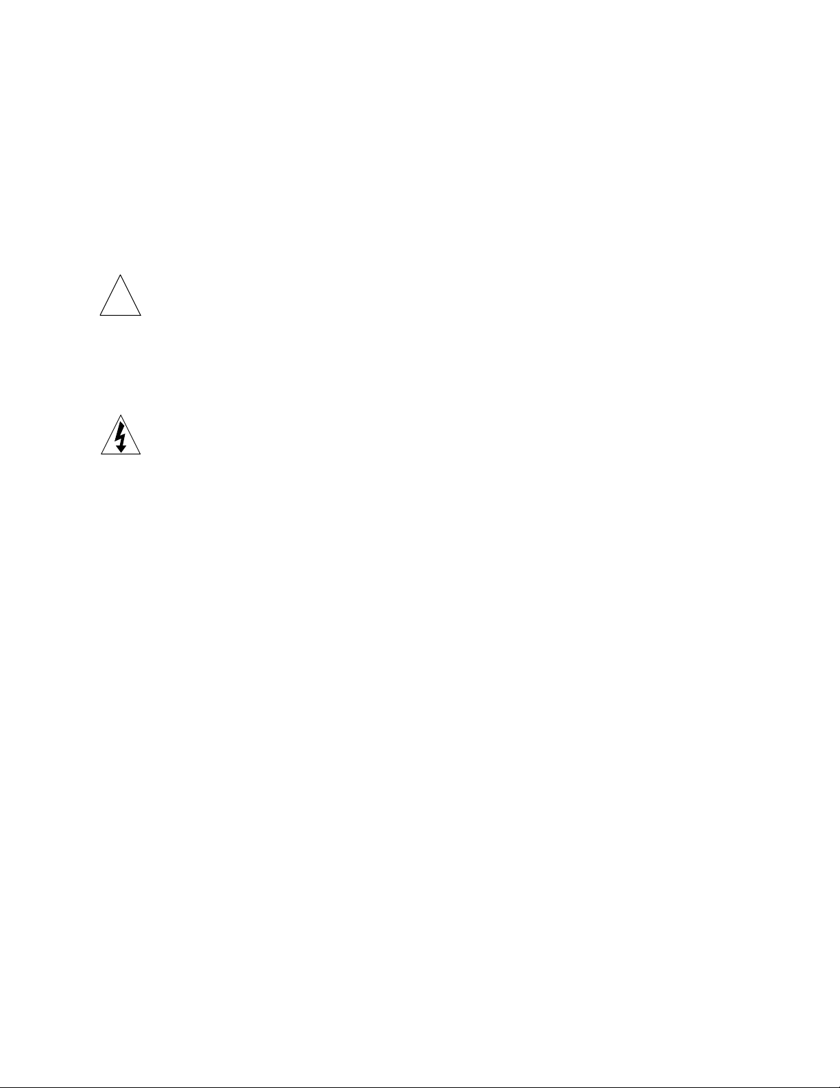
1. Examine the inner portion of an electrode assembly. For the Standard Rotofor
there should be a small O-ring in the central hole on the flat side, and a large
O-ring seated in the large groove around the central shaft on the other side. For
the mini chamber, the outer portion contains only one large O-ring. Place a gasket
over the alignment pins and seat it on the flat surface of the inner assembly. The
three oblong holes in the ion-exchange gaskets should align with the six holes
of the electrolyte chamber. When properly aligned, the gasket should not
obstruct the six holes in any way.
Fig. 3.1. Outer and inner portions of the electrode assemblies. Arrows indicate O-rings. Electrolyte
buffer should just cover the central shaft when completely assembled. For the mini focusing chambers,
the six holes in the inner portion of each electrode assembly are much smaller in diameter than six
holes in the inner portion of the electrode assemblies used with the larger focusing chamber. In addition
the six holes for the mini chamber are drilled at a distinct angle to the central axis of the assembly.
These parts are not interchangeable!
7
Central shaft
Large o-ring
Inner portion
Outer portion
Page 12
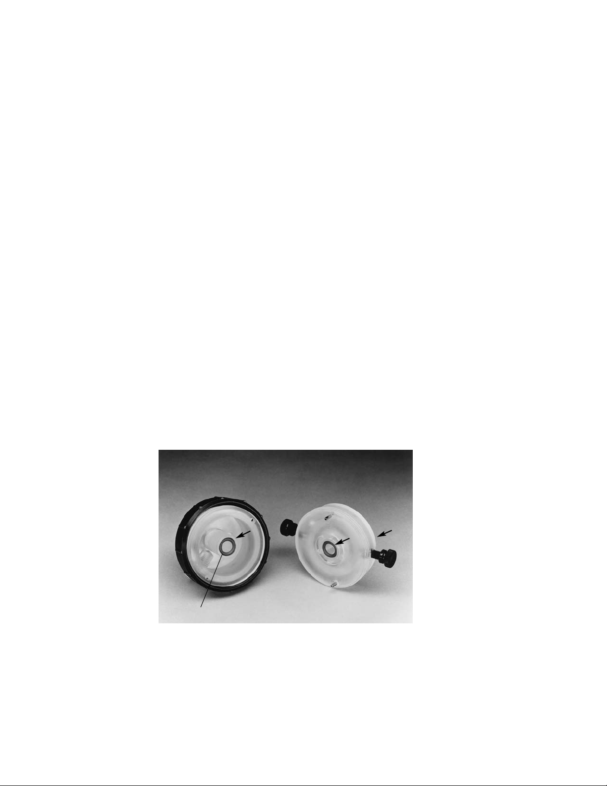
2. Place the proper ion exchange membrane on the gasket by aligning the notches
in the membrane around the pins, and complete a “sandwich” with a second gasket
on top of the membrane. The cathode holds one anion exchange membrane and
the anode holds one cation exchange membrane.
Fig. 3.2. Ion exchange membrane and gasket sandwich on inner portion of electrode assembly.
3. Make sure that there is a small O-ring inset in the central shaft of the large,
outer portion of the electrode assembly and fasten the halves together with the
captive, threaded sleeve.
4. Repeat the assembly process for the second electrode.
5. Fill the electrode chambers with electrolytes immediately after assembly to prevent
the membranes from drying. Filling is most easily accomplished with the assembled
focusing chamber mounted on its stand. The anode (+) electrode assembly (red
button), containing the cation exchange membrane, is filled with acidic electrolyte,
usually 0.1 M H3PO4. The cathode (–) electrode assembly (black button), containing
the anion exchange membrane, is filled with basic electrolyte, usually 0.1 M
NaOH. To fill the compartments, remove the vent buttons, add 25–30 ml of the
appropriate electrolyte to each chamber, so that the chambers are about 65% full,
and replace the buttons. The electrolyte should just barely cover the central shaft
of the chamber. Excessive electrolyte does not provide sufficient air space to allow
gases to escape. Pressure may build up inside the electrode assembly and cause
leaking from the vent buttons or ion exchange membranes.
The vent buttons are interchangeable and can be used with either electrode
assembly. The life of these buttons is usually 4–5 runs. After 4–5 runs, electrolyte
may begin to leak from the vent buttons during the run. If a vent button is
inadvertently perforated or, if during focusing an inordinate amount of electrolyte
leaks from the filling port, stop the run and replace the vent cap.
When the cell is used for the first time, the electrode assemblies will contain fresh
electrolyte. If the cell has been run previously, the distilled water or electrolyte
solutions must be left in the electrode assemblies between runs to maintain
hydration of the ion exchange membranes. Use fresh electrolytes for each run. If
the membranes are allowed to dry, they must be replaced. Empty the electrode
assemblies and fill with fresh electrolyte solution before each focusing run.
8
Page 13
3.3 Assemble the Focusing Chamber
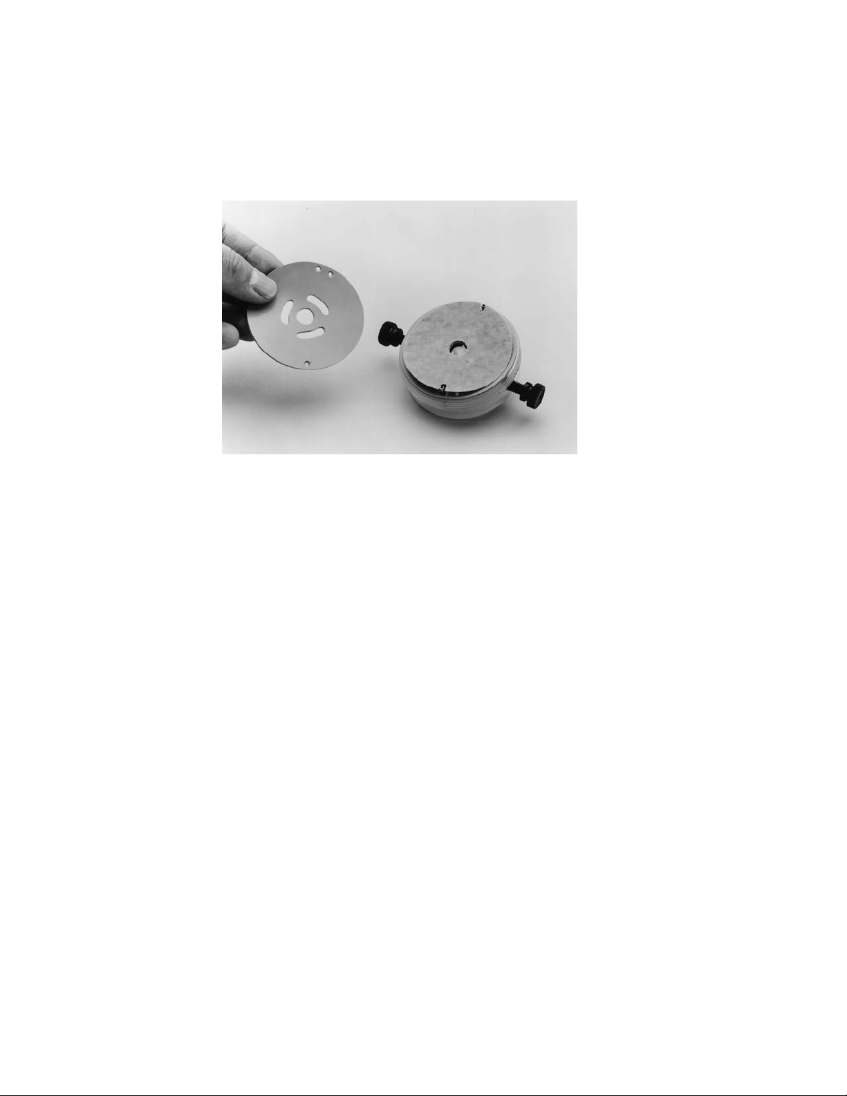
1. Slide the assembled anode electrode assembly over the ceramic cooling finger
so that the two protruding screw heads fit into the holes in the black plastic
base of the cooling finger support assembly.
Fig. 3.3. Anode electrode assembled on the cooling finger.
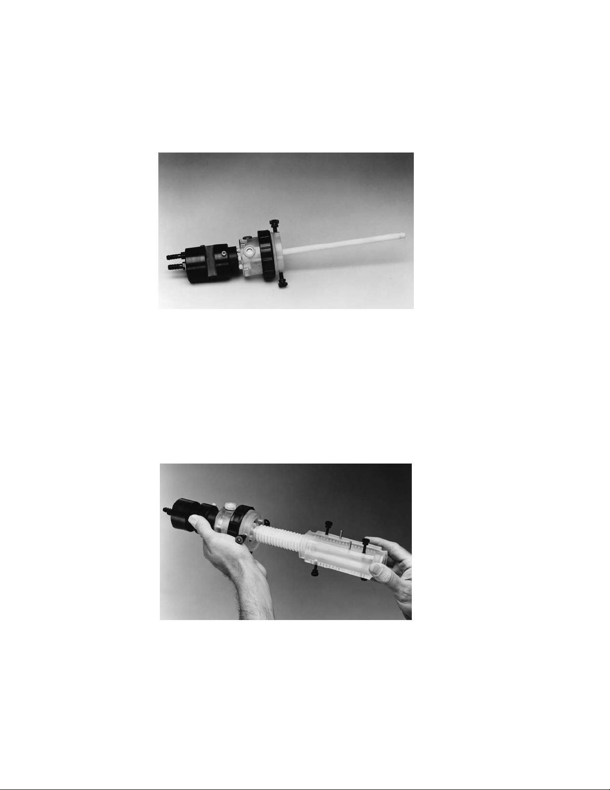
2. Slide the membrane core onto the ceramic cooling finger, making sure the core
abuts the acrylic ridge on the anode chamber.
3. Slide the focusing chamber over the membrane core, inserting the metal pin
into the small hole in the anode chamber. Position the focusing chamber so
that each membrane screen lies between two adjacent ports. These ports must
not be blocked by the membrane screens at either side, load or harvest. If the
ports are blocked, remove the focusing chamber, and slide it once more over
the membrane core. Tighten the black, nylon retaining screws. Check again to
make sure the membrane screens do not block the ports of the chamber.
Fig. 3.4. Slide the focusing chamber over the membrane core.
4. Slide the assembled cathode compartment over the cooling finger, aligning the
metal pin and hole in the cathode chamber, and tighten the nylon retaining
screws.
9
Page 14
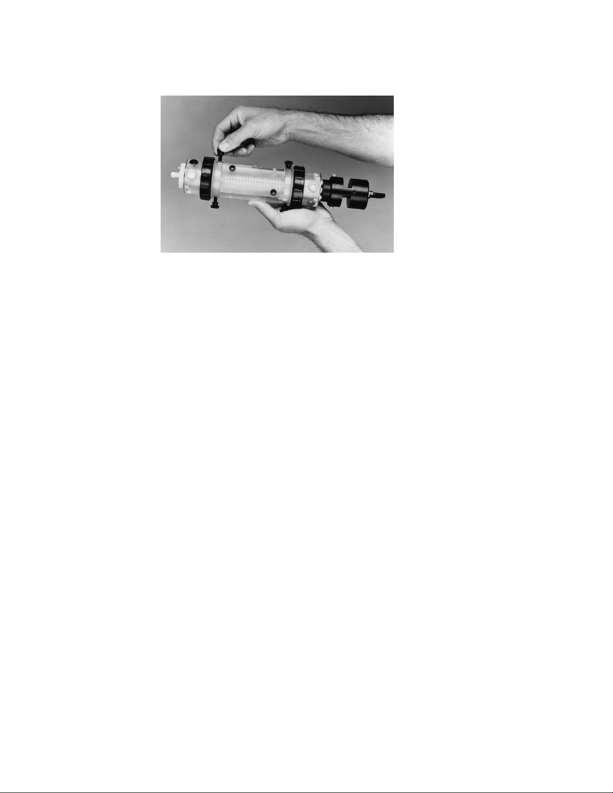
Fig. 3.5. Assembled focusing chamber.
5. Mount the assembled focusing chamber in the stand. The gear on the cathode
electrode assembly should be fully engaged with the gear on the stand. If the
focusing chamber does not slide in easily, remove it to check that all parts are
properly assembled.
6. Attach the power cord to the back of the unit and connect it to an electrical outlet.
3.4 Prepare the Focusing Chamber
With the cell mounted on the stand, rotate the focusing chamber so the 20 collection
ports, identified by the two metal alignment pins, are facing up. Cover the ports with a
piece of the sealing tape provided with the cell. Reinforce the taped ports with one of the
two acrylic cell-cover blocks, and finger tighten the screws. We recommend pre-running
the cell with pure water for the first use or after cleaning the components in the focusing
chamber with NaOH. Pre-running the cell with water for 5 minutes at 5 watts constant
power will remove residual ionic contaminants from the membrane core and ion
exchange membranes before addition of the sample.
3.5 Load the Sample
Rotate the cell so the filling ports face up. This is easily accomplished by flipping
the toggle switches to ON and HARVEST. In the harvest mode the focusing chamber
will automatically stop with the filling ports facing up and the collection ports facing
down. Fill the cell with sample through the ports using a 50 ml syringe with a 1-1/2
inch 19-gauge needle. Typically, every other port is filled, and the sample spreads into
the adjoining compartments. For the large focusing chamber, the minimum sample
volume must be sufficient to cover the cooling finger. For the mini focusing chamber
load the maximum sample volume of 18 ml.
3.6 Seal the Loading Ports
A. Mini Rotofor chamber: Place the grey rectangular, silicone gasket in the slot
containing the loading ports then place the second cell cover block over the
gasket (tape is unnecessary), and the Rotofor cell is ready for operation.
B. Standard Rotofor chamber: Seal the filling ports with only the second cell
cover block (tape is unnecessary), and the Rotofor cell is ready for operation.
10
Page 15

11
3.7 Remove Air Bubbles
During filling, air bubbles can become trapped in the 6 ports of the electrolyte chamber.
This is especially true with the mini focusing chamber. If the bubbles are not removed, they
will produce occasional fluctuations in the voltage and currents due to the discontinuity they
create in the electrical field. Some power supplies, such as the Bio-Rad Power Pac 3000,
have safety sensors that may trip and shut off the voltage in response to the resistance
change that occurs when a bubble rotates into the electrical circuit. Thus, bubbles must be
eliminated prior to commencing electrophoresis. Remove the assembled, loaded cell from
the stand, turn it vertically and tap the electrode chamber to dislodge the bubbles. Then
turn the cell 180° and tap the other chamber. If any air bubbles remain in the 6 ports
between the sample and the ion exchange membranes, repeat this process. When all the
bubbles are eliminated from the electrode ports, return the cell to the stand and start the
fractionation.
Fig. 3.6. Loading the sample.
Section 4
Running Conditions
4.1 Starting the Fractionation
Excessive heating may denature proteins and damage the Rotofor cell.
Connect the ports of the cooling finger to a source of recirculating coolant and
begin coolant flow. The ports are interchangeable, so either one may be connected
to the coolant inlet. It is usually sufficient to set the chiller at 4°C. For more critical
temperature control, the chiller can be adjusted accordingly. At 12 W constant
power (normal operating mode) the coolant temperature should be set at 10°C less
than the temperature desired for the sample. In other words, if the coolant is -6°C
than the sample temperature will be maintained at about 4°C. Attach the cover of
the unit, mating its jacks to the plugs on the base. Allow the system to come to
thermal equilibrium at the cooling temperature before beginning the run, approximately
10–15 minutes.
Page 16
4.2 Power Supply
1. Never operate the Rotofor cell with the cover removed. When focusing power
is applied to the jacks without the cover in place, several high voltage elements
become exposed. To avoid personal injury due to accidental contact with these
elements, always operate the cell with the cover in place.
2. Attach the high voltage leads to the power supply, and the Rotofor cell is ready
for use. To begin rotation, flip the toggle switches to ON and RUN.
3. Power supply:
Standard Rotofor chamber - Set the supply to 15 W constant power and begin
the run.
Mini Rotofor chamber- Set the supply to 12 W constant power and begin the run.
The starting voltage and current will vary depending on the salt concentration of the
sample. For example, if the salt concentration of the sample is 10 mM, the starting
voltage will be 300–500 V, and the current will be 24–40 mA. The maximum power
that can be dissipated is about 15 W for an initial fractionation when the Rotofor cell
is operated at 4°C. If more than 15 W is applied to the cell, overheating can damage
the cell. The applied power is too high if the current increases or remains constant,
rather than decreases, during a run. If a constant power supply is not available,
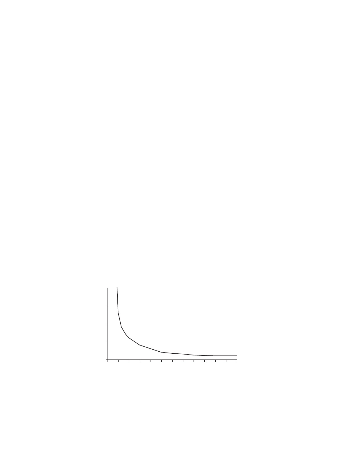
check the graph in Figure 4.1 to determine the optimum starting voltage and
increase the voltage manually in increments over time. The voltage should be
increased as the run progresses to keep the power at a constant 12 W.
4. A typical run is completed in 3–5 hours. To monitor the progress of a run under
conditions of constant power, observe the voltage increase over time. The run
is complete when the voltage stabilizes. At that point, allow the run to continue
for 30 minutes before harvesting. The total run length should not exceed
6 hours. Longer run times do not tighten the focusing and may begin to break
down the gradient.
Fig. 4.1. The maximum power that should be applied to the Rotofor cell is 12-15 W. The graph
shows the voltage and current readouts for setting a constant voltage power supply. If the current
reading is too high at the set voltage (in the danger zone), reduce the voltage until a safe power level is
obtained. Watts = voltage x current.
m Amps
12 W
12
2000
1500
1000
Volts
500
0
0102030405060708090100110120
Page 17

4.3 Fraction Collection
1. Load the test tube rack with twenty 12 x 75 mm culture tubes and place it inside
the harvest box. Place the lid on the box, making certain that each stainless steel
collecting tube is inside a test tube. Connect a vacuum source to the vacuum port
on the box and turn on the vacuum to hold the lid in place. A vacuum pump or
house vacuum of 10–50 mm Hg is recommended.
2. When focusing is completed, move the black toggle switch to the HARVEST
position. This stops the cell rotation with the cell properly aligned for sample
collection, i.e., with the alignment pins and taped collection ports on the bottom
of the focusing chamber. All manipulations which follow the end of rotation
should proceed as quickly as possible to minimize mixing.
3. Turn the power supply off, disconnect the power supply, remove the cover, and
move the Rotofor cell and the harvesting box next to one another. Remove both
the upper and lower focusing chamber cell cover blocks. Mount the needle array
on the two alignment pins on the bottom of the chamber. Grasp the needle array
with the fingers of both hands while placing the thumbs on the top of the focusing
chamber. Take care not to block any of the uppermost ports. Quickly push the
needles firmly and uniformly all the way through the sealing tape into the chamber.
This will cause all 20 fractions to be simultaneously aspirated from the cell and
delivered to the collection tubes.
Fig. 4.2. Harvesting samples after focusing is complete. Make sure thumbs do not cover the
uppermost ports.
4. Turn off the vacuum source and remove the test tube rack. Note that all the
odd numbered fractions are in one row and the even numbered fractions are in
the other row of the rack.
4.4 Refractionation
The fractions containing the protein of interest may also contain other, contaminating
proteins after the initial fractionation. Refractionation of Rotofor fractions is one way to
increase sample purification. Because of its lower volume requirement the Mini Rotofor
chamber is ideal for refractionating pooled fractions.
13
Page 18

After screening the samples collected from the first fractionation, pool the fractions
containing the protein of interest. These pooled samples (typically 3–5 fractions) can
be reapplied either to the Rotofor or Mini Rotofor for refractionation. Rotofor fractions
obtained from an initial run contain ampholytes whose range spans the pI of the protein
of interest. It is best to add no additional ampholytes to the sample to be refractionated.
Because ampholytes and salts are not added prior to the refractionation, higher
voltages can be obtained because of the low ionic strength of the sample. High
voltages lead to better resolution during focusing. Upon refractionation, the
ampholyte range is much narrower and more specific to the protein of interest. The
pooled fractions contain a small part of the initial pH range which spans the pI of
the protein of interest. This is spread across the length of the chamber during
refractionation, providing a shallow pH gradient, and thereby increasing the likelihood
of obtaining one or more fractions of pure protein.
4.5 Final Purification
The Rotofor is designed to quickly separate proteins of interest from other proteins
in a sample. Bio-Rad’s Model 491 Prep Cell can purify individual proteins from Rotofor
fractions by continuous-elution electrophoresis. Conventional gel electrophoresis
buffer systems and media are used with the Model 491 Prep Cell. Using SDS-PAGE
or native-PAGE, the Prep Cell can isolate specific components from complex mixtures
containing micrograms to 200 milligrams of total sample. Up to 5 milligrams per band
can be resolved. Using SDS-PAGE the cell isolates molecules that differ in molecular
weight by 2%. Using non-denaturing PAGE the cell can isolate molecules that differ in
charge by 0.1 pH units. Electrophoretic purification can also be effective in removing
ampholytes from samples. See Section 12.
Section 5
Disassembly and Cleaning
1. Rinse the needle array and its associated tubing with water as soon as possible
after use. Do not use the vacuum box to pull water through the needle array.
This may damage the box. Rinse the box with water.
2. Take the focusing chamber from the stand. Loosen the nylon screws and
remove the cathode chamber.
3. Leave the cathode and anode chambers intact. The ion exchange membranes
must be stored wet. Remove the electrolyte and fill the electrode chambers with
distilled water. If properly stored, the membranes will not decrease in performance
between runs. Before starting a new run, the electrolytes must be replaced with
fresh solutions.
4. Loosen the nylon screws on the anode chamber and remove the focusing chamber
and membrane core. Rinse all chamber components with water and air dry. Do not
expose the focusing chamber to concentrated acid, base, or alcohol. The membrane
core requires additional care, especially if there has been protein precipitation during the
run. A spatula can be used to loosen and remove caked precipitates. Soak the membrane
screens in saline and then in detergent or 0.1 M NaOH to remove traces of protein. An
ultrasonic cleaner will facilitate the cleaning process. Finally, rinse the screens with
water. For complete removal or residual NaOH or other cleaning compounds, assemble
the Rotofor cell with the membrane core, add distilled water, and apply 5W power until
the current stabilizes. Then discard the solution and add the sample. Cleaning with
strong oxidizing agents, such as hypochlorite, or organic solvents should be avoided, as
they will damage the membrane core. If properly cleaned, the membrane core can be
immediately reused.
14
Page 19

Section 6
Sample Preparation
6.1 Salt Concentration
1. Samples should be desalted (e.g., by dialysis or Bio-Gel®P-6 chromatography)
prior to ampholyte addition to insure that the nominal pH range of the ampholyte
will extend over the full length of the focusing chamber and that the maximum
voltage can be applied. It is best to limit salt concentrations in the samples to
about 10 mM for optimum fractionation. However, the maximum salt capacity
will vary with the application, therefore optimum running conditions should be
determined empirically. During focusing, all salts migrate to the compartments
next to the anode and cathode, effectively desalting the sample.
2. The sample should not be in a buffer greater than 10 mM concentration.
Buffers add to the conductivity of a sample and decrease resolution. Also,
buffering solutions may flatten the pH gradient in the region of the pKaof the
buffer.
6.2 Clarification
Turbid sample solutions should be clarified by filtration or centrifugation to
remove extraneous cellular debris that might clog the membrane core.
6.3 Solubility
If the solubility of proteins presents a problem, adjusting the sample to 3–5 M
urea is recommended. Higher urea concentrations, up to 8M urea, can be used.
Be sure to deionize the urea using AG®501-X8 mixed bed ion exchange resin
(catalog number 143-7424). Addition of non-ionic detergents, such as: CHAPS,
CHAPSO, octylglucoside, digitonin, or Triton X-114 is also valuable in maintaining
the solubility of focused proteins. The concentration of detergents used is usually
between 0.1% and 1%. Alternatively, solubility can sometimes be maintained by
increasing the Bio-Lyte ampholyte concentration in the sample. Check the solubility
of the protein by diluting it in detergent or urea and running it on an analytical IEF
gel. If the protein does not show signs of precipitation in the IEF gel, it should not
precipitate in the Rotofor cell.
15
Page 20

Section 7
Optimizing Fractionation
7.1 Ampholyte Choice
1. Bio-Lyte®ampholytes are complex mixtures of synthetic buffering electrolytes with
closely spaced pI’s and high conductivity. Bio-Lytes are supplied at concentrations
of 40% (w/v), except in the pH ranges 3-5 and 8-10, which are at 20%. The final
concentration of Bio-Lytes used in the Rotofor system depends on the protein
concentration in a given sample:
Protein per Bio-Lyte
milliliter Ampholytes
>2 mg 2%
1 mg 1.5%
0.5 mg 1%
0.25 mg 0.5%
2. Up to 8% (w/v) ampholyte concentrations have been used for various applications.
Ampholytes at 1% permit higher applied voltages and are recommended if
refractionation is not required. 2% ampholytes will provide greater buffering and
are necessary when refractionation is performed. If protein precipitation occurs
during the run because of the desalting effect of focusing, sample solubility may
be maintained with higher ampholyte concentrations. Use the following formula to
determine the appropriate volume (V1) of a 40% Bio-Lyte ampholyte solution to
give a desired final concentration in your Rotofor sample.
For the equation: (C1)(V1)=(C2)(V2), solve for V
1.
where: C1= Starting concentration of Bio-Lyte (40%)
V
1
= Unknown volume of 40% Bio-Lyte to give desired final
concentration
C
2
= Final or desired concentration of Bio-Lyte
V
2
= Final volume of the sample to be applied to the Rotofor
(35–58 ml) or Mini Rotofor (18 ml)
3. The pI of the protein of interest can be determined by running the sample on a
flatbed slab IEF cell (such as the Model 111 mini IEF cell) using the broad pH
range of 3-10. IEF markers (catalog number 161-0310) run in the same gel
allow the pI of the protein of interest to be estimated. Alternatively, the pI can
be estimated by running the sample in the Rotofor cell using a broad range
3–10 ampholyte. The pI of the protein of interest will correspond to pH of the
Rotofor fraction where the protein of interest focuses.
4. A narrow pH range of ampholytes spanning the pI of the protein of interest should
be used for the initial fractionation. Narrow range fractionation first separates the
protein of interest from the bulk of its contaminants. The pI of the protein of interest
should fall in the middle of the ampholyte range.
16
Page 21

5. An example of the importance of using the proper ampholytes in a fractionation is
demonstrated by a purification of Japanese water moccasin snake venom. The
protein of interest has a pI of 6.1 as determined by IEF gels. Bio-Lyte ampholytes
pH 6-8 were used for the initial fractionation. The fractions were analyzed and the
ones containing the specific protein were pooled. After refractionation, the fractions
were again analyzed on IEF slab gels and multiple bands were observed in all
fractions. When the same snake venom sample was initially fractionated in 5-7 Bio-Lyte
ampholytes the results were dramatically different. After refractionation, the protein
of interest was almost completely free of contaminating proteins. The conditions for
both experiments were identical except for the initial Bio-Lyte range; however,
much greater purity was obtained from the experiment using the 5-7 Bio-Lyte
ampholytes.
7.2 Sample Capacity
Choosing between the Standard Rotofor Chamber and the Mini Rotofor
Chamber is a matter of sample size. The Standard Rotofor Chamber is designed to
optimally fractionate milligrams to grams of total protein. The Mini Rotofor chamber is
designed to fractionate micrograms to milligrams of total protein. The smaller volume
of the Mini Rotofor decreases sample volume and is best suited for use with samples
of low protein concentration. Protein concentrations should be adjusted for desired
yield or to provide convenient assays of focused material, assuming each component
will focus in 1–3 channels, approximately equal to 3 ml/fraction in the Rotofor and
800 µl/fraction in the Mini Rotofor.
For example, if Rotofor fractions are analyzed by SDS-PAGE on a Mini-PROTEAN
®
II cell (catalog number 165-2940) and silver stained, the sample should contain a
minimum of 50.0 µg per component. More sensitive assays, such as activity assays,
decrease the necessary protein load.
The maximum protein load varies with the solubility of each sample and must be
determined empirically. However, preparative fractionation of 51 ml of lyophilized
cell culture supernatant containing 2.4 g of protein has been successfully performed
using the Rotofor Cell.
7.3 Power Conditions
We recommend running the Rotofor cell at constant power. During the initial
fractionation the voltage values will vary between samples depending on the relative
concentration of proteins and salts. The Mini Rotofor should be run using 12W constant
power and standard Rotofor should be run using 15W constant power.
When voltage is applied to a system of ampholytes and proteins, all the
components migrate to their respective pIs. In electrofocusing, the higher the voltage
the better the resolution. The limiting factor in achieving high resolution is how
efficiently electrically generated heat can be dissipated.
In a constant power mode, voltage gradually increases as the components focus.
The progress of the run is easily monitored by observing the voltage increase over
time. When the sample is focused, voltage levels off at a maximum. Runs typically
last 2-4 hours at 12 watts constant power and can require up to 3000 volts.
7.4 Cooling
Sample temperature affects activity and resolution. Many proteins, especially
enzymes, are temperature labile. The water recirculation chiller should be set about
10 °C cooler than the temperature required to maintain stability of your protein. The
17
Page 22

heat generated during IEF keeps the temperature inside the focusing chamber
approximately 10 °C higher than that of the circulating coolant. Temperature settings
for chillers are generally between - 10°C and 4°C.
Diffusion rates of proteins are proportional to their temperature in solution.
Because proteins at steady state diffuse in and out of their focused zones it is
advisable to run the Rotofor cell at the lowest possible temperature to offset this
effect.
7.5 Electrolytes
The recommended electrolytes for the anode and cathode are 0.1 M H3PO
4
and 0.1 M NaOH, respectively. Because there can be a slight amount of electrolyte
exchanged through the ion exchange membranes during the focusing run, the first
one or two channels may be very acidic (<pH 3) and the last one or two channels
may be very basic (>pH 10). The result will be a concentration of the effective pH
gradient in the middle channels. This will have minimal affect on the final results of
the experiment. Alternative electrolytes, e.g., amino acids, acetic acid, etc., may be
used and perform as well as H3PO4and NaOH. These include:
7.6 Pre-running the Cell
The unit should be cleaned with distilled water prior to loading the sample.
Simply fill the focusing chamber with 55 ml of distilled water and run at standard
power for 5 minutes. Drain the unit using the harvesting apparatus. This will insure
that extraneous ions have been removed from both the cell and the surface of the
ion exchange membranes.
7.7 Prefocusing
Loading the sample into the Rotofor cell is usually accomplished by injecting a
homogeneous solution of the prepared sample containing ampholytes, the protein
of interest, and any required solubility agents into the focusing chamber. However,
some proteins are especially sensitive to rapid pH shifts or to extremes of pH and
may precipitate or become denatured. To avoid exposing your protein to these
potentially damaging conditions during initial focusing, “prefocus” the focusing
media (i.e. Bio-Lyte ampholytes and solubility additives), without protein for about
an hour. This will establish the pH gradient. Then inject your protein sample into
the sample chamber at or near the point in the pH gradient that corresponds either
to the pH of the protein sample solution or the pI of your protein of interest. To
avoid disrupting the pH gradient during injection of the sample, this technique
requires that the volume of the solution containing the protein sample be as small
as possible. Prefocusing decreases exposure of proteins to rapid pH shifts and pH
extremes, minimizes the amount of time the protein spends in the Rotofor cell, and
may reduce run times by up to 50%.
18
3-5
4-6
5-7
6-8
7-9
8-10
0.5 M acetic acid
0.5 M acetic acid
0.1 M glutamic acid
0.1 M glutamic acid
0.25 M MES
0.25 M MES
0.25 M HEPES
0.5 M ethanolamine
0.5 M ethanolamine
0.1 M NaOH
0.1 M NaOH
0.1 M NaOH
pH range of Anode Cathode
Bio-Lyte Electrolyte Electrolyte
Page 23

7.8 Refractionation
Better separation may be achieved by refractionating the sample. The mini Rotofor
is ideal for refractionation because samples are minimally diluted in its chamber. After
analyzing the fractions from the initial separation, the fractions containing the protein of
interest should be diluted in distilled water and reloaded in the standard Rotofor cell or
the Mini Rotofor cell. Upon refractionation the ampholyte concentration should be at
least 0.5%. We recommend that no less than 4–5 fractions be pooled and reapplied for
a second Rotofor run. If urea or non-ionic detergents are needed to maintain protein
solubility add the same concentration as used in the first fractionation. Do not add
additional ampholytes or salts at this stage.
1. Dilute pooled fractions appropriately, e.g., with water, up to 8 M urea, or a solution
containing non-ionic detergent for solubility, to a final volume of 55–60 ml in the
standard Rotofor or 18 ml for the Mini Rotofor. The customized ampholyte blend
obtained will span the pI of the protein of interest. Do not add additional ampholyte
to the refractionation mix; the amount present in the pooled samples is suitable for
focusing and provides a narrow range pH gradient to increase separation of the
protein of interest.
2. Load the diluted sample and re-run. Since the ionic strength of the sample will
be lower upon refractionation, higher voltages, yielding better separations can
be achieved. Refractionations of low ionic strength solutions have been carried
out at 2,000–3000 volts. Do not exceed the power limit of the cell. Focusing is
usually complete in 3–5 hours. The upper limit for voltage is dependent on how
well heat can be dissipated. Set the coolant temperature between -5°C and -10°C
for high voltage separations.
Section 8
Analysis of Results
8.1 Fraction Analysis
After harvesting, it is important to analyze the fractions to determine which contain
the protein of interest. There are many different ways of doing this, and the best
method is dependent on the protein being analyzed.
SDS-PAGE analysis or an IEF gel, usually pH 3-10, will give an accurate
representation of the fractionation. Other methods for assaying which channels
contain the protein of interest are dependent on the particular protein and include
activity assays and antibody tests. Analytical gels should be silver stained for high
sensitivity detection of contaminants.
8.2 Separation of Ampholytes From Proteins
Many applications can tolerate the presence of ampholytes in protein solutions.
However, ampholytes can interfere with some assays such as amino acid analysis.
Several methods for separating ampholytes from focused proteins are listed below.
1. Preparative Electrophoresis - Rotofor fractions containing the protein of interest
and any remaining contaminating proteins can be pooled and applied to a
preparative continuous-elution electrophoresis cell such as Bio-Rad’s Model
491 Prep Cell. Using the Model 491 Prep Cell as second and a final purification
step, samples (Rotofor fractions) are electrophoresed through a polyacrylamide
gel. In this way, the contaminating proteins and the ampholytes are effectively
separated from the protein of interest.
19
Page 24

2. Dialysis - Probably the simplest method for ampholyte removal is dialysis.
Adjust the pooled sample to 1 M NaCl. This will effectively strip electrostatically
bound ampholytes from proteins by ion exchange. Then dialyze into the buffer
appropriate for further uses.
3. Ammonium sulfate precipitation of proteins may also be effective in removing
ampholytes from samples.
4. Any number of chromatographic techniques, such as gel filtration, ion
exchange, hydroxylapatite, affinity chromatography, or use of AG 501-X8 resin,
can be used to separate proteins from ampholytes.
Section 9
Troubleshooting Guide
This guide is designed to answer common Rotofor cell questions. For further
information, please contact your local Bio-Rad representative. In the U.S., our
Technical Service department is available Monday to Friday, from 7:00 am to 5:00 P.M.
Pacific Time to answer all of your technical inquiries involving Bio-Rad equipment and
reagents. You can reach us by dialing 1-(800)-4BIORAD.
9.1 Solubility and Precipitation of Proteins
1. By definition, a protein at its isoelectric point (pI) has no net charge. Because little
charge repulsion exists between focused molecules, hydrophobic interactions
between proteins become predominant causing proteins to aggregate.
Maintaining the solubility of proteins in this case requires overcoming protein-protein
interactions. Several agents promote protein solubility. Detergents provide a
hydrophobic environment for proteins to mask interprotein interactions. Disulfide
bridges also may form between proteins leading to aggregation. This effect may
be overcome by the addition of reducing agents to the focusing media. Because
the solubility of proteins varies greatly, there is no one answer to the problem of
insolubility. Generally, the easiest method of getting proteins to remain in solution
is to add nonionic detergents, zwitterionic detergents, and/or chaotrophic agents
to the sample mixture.
In addition, glycerol from 5-25% (v/v) in the sample is highly effective for
maintaining the solubility and stability of proteins. Glycerol stabilizes water
structure and the hydration shell around proteins.
Table 9.1. Recommended Solubilizing Agents for the Rotofor System
Non-Ionic Zwitterionic Reducing Chaotropic
Detergents Detergents Agents Agents
0.1-3.0% Digitonin 0.1-3.0% CHAPS DTE 5-20 mM 1.0-8.0 M Urea
0.1-3.0% Octylglucoside 0.1-3.0% CHAPSO DTT 5-20 mM 0.1-2.0% Glycine
0.1-3.0% Triton X-114 BME 1-5 mM 0.1-2.0% Proline
2. When the solubility of a protein depends on maintaining high ionic strength during
focusing, increasing the concentration of Bio-Lyte ampholytes up to 5–8% in
your sample will help keep proteins in solution.
20
Page 25

3. Decreasing the protein load will also help keep the protein in solution. The
largest amount of protein concentration in solution that has been successfully
fractionated in the Rotofor cell is 4 grams. The lower limit for protein loading
depends on the sensitivity of your detection system.
9.2 Factors Affecting the pH Gradient
Non-linear pH gradients are rarely observed when sample is prepared properly
and the Rotofor cell and its parts are carefully maintained. A non-linear pH gradient
may be caused by one or more of the following:
1. Electrolyte leakage. Excessive leakage of electrolyte across the ion exchange
membranes into the focusing chamber will decrease the number of fractions on
the linear portion of the pH gradient and reduce the effective voltage across the
sample. To determine if this is occurring, check the pH of the fractions.
Alternatively, fill the Rotofor focusing chamber with distilled, deionized water
and run the Rotofor at 12 W constant power. If the amperage does not
decrease to < 6 mA and the voltage does not increase to near 2,000 V within
5–10 minutes, the chances are good that you have electrolyte leaking into your
sample. Some common causes are:
A) Expired Vent Buttons. Vent buttons lose their capacity to vent the gases
produced during electrolysis over time and when there is too much electrolyte
in the chamber. The pressure that results within the electrolyte chambers
forces electrolytes into the focusing chamber. Replace the vent buttons (catalog
number 170-2957) every 4 to 5 runs.
B) Worn O-rings and/or electrode Gaskets. The Rotofor repair kit contains
replacement parts for these items (catalog number 170-2953). Lubricating
the O-rings with a small amount of silicone O-ring grease or Cello-Seal
™
will extend their useful lifetime (catalog number 170-2954).
C) Cracked, dehydrated, or worn out Ion-exchange Membranes (catalog number
170-2956). These last 4 to 5 runs.
2. Uneven harvesting. Variations in the volumes of harvested fractions may affect
the linearity of the collected pH gradient. Be sure to remove both harvesting and
loading port covers before piercing the sealing tape with the harvesting block
needles. Also make sure that the harvesting tubes are clean and clear of blockages
by soaking in Bio-Rad cleaning concentrate (catalog number 161-0722) or dilute
0.05 M NaOH and rinsing well with DDI H2O after each run. Dry the tubes by
aspirating each individual tube with a vacuum line. Be careful not to block the
loading port holes with your fingers during harvesting.
The compartments of the focusing chamber contain unequal volumes at the
end of the run. As proteins become focused the osmotic pressure in each
Rotofor compartment may vary. If the focusing chamber is not completely full,
this may cause unequal distribution of fluids in the 20 compartments. This
effect will vary as a function of protein load and concentration of solubilizing
additives. Reproducibility of results, especially where isolation of a protein in a
particular fraction number is expected, will depend on the constancy of these
factors. To alleviate the osmotic effect, the Rotofor cell should be run with the
focusing chamber completely filled.
3. Premature harvest. Too short a run will result in a partially-formed pH gradient
and poorly focused proteins. The Rotofor cell is normally run for 3 to 6 hours.
To assure complete focusing, continue the run for 1/2 hour after the voltage
stabilizes, then stop the electrophoresis and harvest the focused protein.
21
Page 26

4. High salt sample. The salt (or buffer) concentration in the sample may be too
high. This will decrease the effective voltage across the sample and may reduce
the number of fractions on the linear portion of the pH gradient. Resolution is
dependent on both high voltage and maximizing the number of fractions on the
linear gradient. If a particularly high ion concentration is necessary to preserve
the stability and/or activity of your protein, Bio-Lyte ampholytes (which are ionic
molecules) may be substituted for salts. For example, preparation of the enzyme
aldose reductase (pI ~ 5.0) from porcine lens for purification using the Rotofor
cell required that the protein sample be at low ionic strength (< 1.0 mM buffer)
to maximize voltage and resolution10. Since aldose reductase is unstable under
these conditions, the following procedure was used to avoid exposure to low
ionic strength:
1.0 ml of 5% Bio-Lyte ampholytes, previously fractionated using the Rotofor cell at
4.5 to 5.5 pH range, were added to 1.0 ml of 5.0 mg / ml protein solution in a 10.0
mM phosphate buffer. This solution was exhaustively dialyzed against 25.0 ml of
the same 5% Bio-Lyte solution, thereby making the final phosphate concentration
less than 1 mM. The salt concentration in the sample was reduced to a reasonable
level while the ionic strength required to maintain the stability of the enzyme was
retained.
If the pH gradient plateaus or dips near the middle, this may be due to the presence
of excess buffer in the protein sample solution. The pH of the gradient will be
buffered at the pK of this buffer, creating a dip or plateau in the gradient in this
region. The symptom may be many fractions with the same pH. Reduce buffer
salts to < 10 mM.
5. High sample temperature. At 12 W, the temperature inside the chamber is generally
10 degrees higher than the temperature of the circulating coolant. The cooler the
run, the more stable the proteins will be. 4 °C is the optimum sample temperature.
6. Non-reproducible pH gradients. Use sufficient concentration of ampholytes.
Batches and brands of ampholytes may also vary. Do not run the Rotofor cell
more than 1–2 hours after voltage stabilization. Reduce salt to below 10 mM.
Always run the sample at or below 4°C. Check the integrity of the Bio-Lyte
ampholytes. Ampholytes should be stored at 4°C in the dark. Guaranteed shelf
life of opened Bio-Lyte ampholytes is 1 year.
9.3 Recovery of Biological Activity
1. pH. Some proteins are especially sensitive to rapid pH shifts and to extremes of
pH that exist at the extreme ends of the Rotofor focusing chambers. To avoid
exposing your protein to these potentially damaging pH extremes during initial
focusing, “prefocus” the focusing media (i.e. Bio-Lyte ampholytes, additives,
water, etc.), without protein, for about an hour. This will establish the pH gradient.
Then inject your protein sample into the sample chamber at or near the point in
the pH gradient that corresponds either to the pH of the protein sample solution
or to the pI of your protein of interest. Addition of your protein sample solution in
as small a volume as possible decreases exposure to rapid pH shifts and pH
extremes, minimizes the amount of time the protein spends in the Rotofor cell
and maintains native tertiary structure.
22
Page 27

2. Temperature. Many proteins, especially enzymes, are temperature labile. Make
sure that the water recirculation chiller is set 10°C cooler than the temperature
required to maintain stability of your protein. The heat generated during IEF
keeps the temperature inside the focusing chamber approximately 10°C higher
than that of the circulating coolant. Temperature settings for chillers are generally
between - 10°C and 4°C.
Diffusion rates of proteins are directly proportional to their temperature.
Because proteins at steady state diffuse in and out of their focused zones it is
advisable to run the Rotofor cell at the lowest possible temperature to offset
this effect.
3. Ampholytes. Ampholytes may form weak electrostatic complexes with proteins.
They can be removed by bringing pooled fraction(s) to 1.0 M NaCl and dialyzing
against appropriate buffer or water. The salt effectively exchanges for the
ampholytes on the protein. This may be followed by dialyzing against appropriate
assay buffer. Other methods for ampholyte removal include electrophoresis;
ammonium sulfate precipitation; and gel filtration, ion-exchange, and hydroxylapatite
chromatography. Be sure to measure the pH of the fractions before manipulating
them to remove ampholytes.
4. Urea. Urea in the focusing media at 3 M generally alleviates precipitation.
Without the use of urea, loss of activity due to precipitation may be excessive.
Urea at higher concentrations (4-8 M) is often used. Following focusing, dialysis
will remove urea from the solution.
5. Detergents. Both the concentration and the type of detergent used play an
important role in recovery of activity. Use the least amount of compatible detergent
required to maintain the solubility of your protein. Also try other non-ionic or
zwitterionic detergents. Removal of detergent from Rotofor fractions may be
necessary for full recovery of activity.
6. Precipitation. Protein-protein interactions may result in activity loss.
Decreasing the protein load, and addition of detergents, glycerol, reducing
agents and/or chaotropic agents keep proteins from forming complexes during
focusing.
7. Proteins are not always active at their pI. Adjust the pH of the solution for
assay.
8. Some proteins require the presence of a particular ionic species for activity
(i.e. mono- or divalent cations like Na+or Mg
2
+
). Replace the ions, if necessary,
for assay.
9.4 Maximizing Resolution
1. Diffuse or multiband protein IEF patterns can arise from molecular interactions
and conformational changes as well as from inherent isoelectric microheterogene-
ity. Ampholytes can reversibly bind to proteins, proteins can undergo sequential
pH dependent conformational changes, and proteins can interact with one anoth-
er. These types of reactions can artifactually alter the pH profiles of proteins. On
the other hand, many proteins are inherently heterogeneous, consisting of isoelec-
tric isomers. To distinguish between artifactual and inherent heterogeneity, it may
be necessary to run an analytical IEF gel in the presence of all constituents to be
used during focusing in the Rotofor cell (i.e., detergents, urea, glycerol, etc.) in the
same proportions to be used in the Rotofor cell. Single focused bands should be
cut out and rerun. If this single band splits into many bands, artifact formation is
indicated. In this case the Rotofor “prefocusing” protocol is recommended.
23
Page 28

2. Clarify all sample solutions before focusing. Membrane cores are composed of
polyester membranes with a pore diameter of approximately 10 µm. The membrane
core can become clogged with insolubles in sample solutions. Starting solutions can
be clarified by centrifugation. To clean the membrane core, soak it in detergent,
dilute NaOH, or sonicate. Rinse the core well in distilled water after cleaning. For
complete removal of residual base, assemble the Rotofor cell with the membrane
core and prerun the cell with H2O until the voltage stabilizes. Then discard the water
and add sample. Generally the membrane cores will last at least 20 runs if they are
well cared for.
3. Protein samples that contain a charged detergent, like SDS, may experience a
shift in apparent pI and migrate to one or another end of the cell as a result of
acquired net charge. Use only non-ionic or zwitterionic detergents for this reason.
Some proteins are inherently associated with phospholipids, heme groups, or
other charged groups that affect the electrophoretic migration of proteins in a
pH gradient. A means must often be found to neutralize the effects that these
charged groups have on proteins during focusing. For example, the non-ionic
detergent, digitonin, has been found to be effective at disassociating negatively
charged phospholipid from integral membrane proteins. Digitonin provides a
suitable hydrophobic environment for maintaining the stability and biological
activity of these proteins during focusing in the Rotofor cell.
9.5 Power Conditions
Voltage is the driving force behind isoelectric focusing. Maximizing the voltage is
the best way to increase resolution. The cooling finger is capable of dissipating up
to 15 W of power generated in the large focusing chamber. The main factor limiting
voltage is efficiency of heat dissipation. These are common problems related to the
application of power.
1. Voltage fluctuations are caused by air bubbles trapped between the sample
and the ion-exchange membranes. Remove the assembled Rotofor core, hold
it vertically and tap on it to dislodge the bubbles. Turn the cell 180° and repeat
the bubble removal process. The minimum running volume of sample solution
should not be less than 35 ml for the standard focusing chamber and 18 ml for
the mini chamber.
2. Voltage decreasing at the beginning of the run is normal. At the beginning
of a run mobile charge carriers migrate through the chamber creating a relative-
ly high initial current. Eventually, desalting ceases and the pH gradient forms. As
the run proceeds, the resistance of the focusing medium increases and voltage
climbs. Do not set a limit on the voltage below 2,000 volts. When the voltage
finally plateaus, steady state has been achieved. Let the run continue for an
additional 15-30 minutes, then harvest.
3. Arcing between the anode and/or the cathode contact plate(s) and the contact
assembly(s) may occur for either of two reasons: 1) the solid brass points of the
contact assembly(s) are worn down and electricity is jumping across the gap, or
2) there is a leak in the coolant from the cooling finger housing and the coolant is
making the electrical connection. Either replace the contact assemblies left side
(catalog number 100-3780) or right side (100-3790) or repair the leaking cooling
finger with new O-rings from the Cooling Finger Repair Kit (catalog number
170-2954).
24
Page 29

9.6 Uneven Harvesting
1. Use a stronger vacuum. Use vacuum that pulls >5 inches mercury.
2. Remove both harvesting and loading port covers. Before puncturing the
sealing tape to aspirate the fractions, remove both upper and lower covers. Do
not cover loading port holes with your fingers or gloves.
3. Run the Rotofor cell completely full. Volumes will vary in compartments as
the result of protein concentrations in each.
4. Check the needles in the harvesting block, the tubing and the harvest
block lid. They should not be loose, kinked, plugged, or unequal in height.
5. Check the plastic harvest tubing. If necessary, soak the tubes in dilute
NaOH (0.1 M) to remove residual matter then rinse the tubes with water.
Caution: DO NOT insert all of the needles into a water bath at the same time
with the vacuum on, as the harvest box may implode! Dry the tubes one at a time.
9.7 Mechanical Problems
1. The cell doesn’t rotate. Make sure that the core is assembled tightly, and that the
gear teeth are meshing well. With each hand, grab the big black rings that hold the
halves of the electrolyte chambers together and tighten them simultaneously for
better leverage. (Also make sure that the switch is set to “run” and not “harvest”).
Refer to the manual for proper assembly.
2. The unit leaks. Leaks from different places indicate different problems:
A) Vent buttons may become wet under normal operation, but this is usually
attributable to condensation during the run, not to leaking. If they are old
(>4–5 runs), or the electrolyte chamber is more than 2/3 full, they may
actually leak. Replace the vent buttons if they are old. Make sure electrolyte
solutions are 0.1 Molar.
B) Check the ion exchange gaskets between the two halves of the electrolyte
chamber to make sure that there is a good seal between them. They
should not be wrinkled, pinched, or out of alignment.
C) Check the O-rings that seal the chamber from the cooling finger. If one or
more of them is twisted, cracked, or missing, the unit may leak. To keep
the O-rings from twisting as you put the unit together, lubricate them with a
small amount of silicone grease, or Cello-Seal.
D) The cell must be seated firmly in the electrodes with the screws tightened.
3. The focusing chamber is too long for the base. Push the assembled
components all completely together on the cooling finger. To properly seat the
pieces together may require some force.
25
Page 30

Section 10
Maintenance Guide
10.1 Vent Buttons
The vent buttons should last four or five runs. They should be inspected before
use for tears in the fabric. If there are any tears, or if leaking occurs during the run,
replace the vent buttons (catalog number 170-2957). Leaking may be due to
overfilling the electrode assemblies. Make sure the assemblies are not filled more
than 65% full. Air space is needed above the electrolyte to allow gas to escape
through the buttons. If the air space is insufficient, pressure may build up and
cause leaking.
10.2 O-rings
The O-rings in the electrode assemblies should be inspected after the first
20–30 runs. If there are any signs of wear, replace them using the O-rings supplied
in the Repair Kit (catalog number 170-2953). If the O-rings are unworn after the
first 20 runs, check them every five runs after that until they need to be replaced.
10.3 Cooling Finger O-rings
Inspect the cooling finger O-rings every 200 runs or every year, which ever
comes first. If there are signs of wear, replace them using the O-rings supplied in
the Cooling Finger O-ring Kit (catalog number 170-2954).
10.4 Membrane Core
The membrane core does not have a replacement schedule. It should be
inspected after each run. If it becomes deformed (through overheating or mechanical stress), it should be replaced.
26
Page 31

Section 11
Rotofor References
Methods
Whether alone or in combination with other techniques- polyacrylamide gel
electrophoresis (PAGE), electroelution, or chromatography, for example- the
Rotofor system integrates into any purification scheme. The following articles
illustrate the use of the Rotofor in a variety of different protein purification and
enrichment methods.
Westman-Brinkmalm A, Davidsson P (2002)
Comparison of preparative and analytical two-dimensional electrophoresis for isolation and
matrix-assisted laser desorption/ionization-time-of-flight mass spectrometric analysis of
transthyretin in cerebrospinal fluid.
Anal. Biochem. 301: 161-7.
Madoz-Gurpide J, Wang H, Misek DE, Brichory F, Hanash SM (2001)
Protein based microarrays: a tool for probing the proteome of cancer cells and tissues.
Proteomics. 1(10):1279-87.
Hesse C, Nilsson CL, Blennow K, Davidsson P (2001)
Identification of the apolipoprotein E4 isoform in cerebrospinal fluid with preparative
two-dimensional electrophoresis and matrix assisted laser desorption/ionization-time of
flight-mass spectrometry.
Electrophoresis. 22(9): 1834-7.
Davidsson P, Paulson L, Hesse C, Blennow K, Nilsson CL (2001)
Proteome studies of human cerebrospinal fluid and brain tissue using a preparative
two-dimensional electrophoresis approach prior to mass spectrometry.
Proteomics. 1(3): 444-52.
Gustafsson E, Thoren K, Larsson T, Davidsson P, Karlsson KA, Nilsson CL (2001)
Identification of proteins from Escherichia coli using two-dimensional semi-preparative
electrophoresis and mass spectrometry.
Rapid Commun Mass Spectrom. 15(6): 428-32.
* Nilsson CL, Larsson T, Gustafsson E, Karlsson KA, Davidsson P (2000)
Identification of protein vaccine candidates from Helicobacter pylori using a
preparative two-dimensional electrophoretic procedure and mass spectrometry.
Anal Chem. 72(9): 2148-53.
* Wall DB, Kachman MT, Gong S, Hinderer R, Parus S, Misek DE, Hanash SM, Lubman
DM (2000)
Isoelectric focusing nonporous RP HPLC: a two-dimensional liquid-phase separation method
for mapping of cellular proteins with identification using MALDI-TOF mass spectrometry.
Anal Chem. 72(6): 1099-111.
Nilsson CL, Puchades M, Westman A, Blennow K, Davidsson P (1999)
Identification of proteins in a human pleural exudate using two-dimensional preparative liquidphase electrophoresis and matrix-assisted laser desorption/ionization mass spectrometry.
Electrophoresis. 20(4-5): 860-5.
* A reprint of this article is available in the Rotofor technical folder.
27
Page 32

Puchades M, Westman A, Blennow K, Davidsson P (1999)
Analysis of intact proteins from cerebrospinal fluid by matrix-assisted laser
desorption/ionization mass spectrometry after two-dimensional liquid-phase electrophoresis.
Rapid Commun Mass Spectrom. 13(24): 2450-5.
Davidsson P, Puchades M, Blennow K (1999)
Identification of synaptic vesicle, pre- and postsynaptic proteins in human cerebrospinal fluid
using liquid-phase isoelectric focusing.
Electrophoresis.20(3): 431-7.
Yvon S, Rolland D, Charrier JP, Jolivet M (1998)
An alternative for purification of low soluble recombinant hepatitis C virus core protein:
preparative two-dimensional electrophoresis.
Electrophoresis. 19(8-9): 1300-5.
Weldingh K, Rosenkrands I, Jacobsen S, Rasmussen PB, Elhay MJ, Andersen P
(1998)
Two-dimensional electrophoresis for analysis of Mycobacterium tuberculosis culture filtrate
and purification and characterization of six novel proteins.
Infect Immun. 66(8): 3492-500.
Ayala A, Parrado J, Machado A (1998)
Use of Rotofor preparative isoelectrofocusing cell in protein purification procedure.
Appl Biochem Biotechnol. 69(1): 11-6.
Masuoka J, Glee PM, Hazen KC (1998)
Preparative isoelectric focusing and preparative electrophoresis of hydrophobic Candida
albicans cell wall proteins with in-line transfer to polyvinylidene difluoride membranes for
sequencing.
Electrophoresis. 19(5): 675-8.
Lucietto P, Fossati G, Ball HL, Giuliani P, Mascagni P (1997)
Mycobacterium tuberculosis chaperonin 10 and N-truncated fragments. Their synthesis and
purification by the isoelectric focusing technique carried out in solution.
J Pept Res.49(4): 308-23.
Goldfarb MF (1993)
Use of Rotofor in two-dimensional electrophoretic analysis: identification of a 100 kDa
monoclonal IgG heavy chain in myeloma serum.
Electrophoresis. 14(12): 1379-81.
Shimazaki K, Kawaguchi A, Sato T, Ueda Y, Tomimura T, Shimamura S (1993)
Analysis of human and bovine milk lactoferrins by Rotofor and chromatofocusing.
Int J Biochem 25(11): 1653-8.
Caslavska J, Gebauer P, Odermatt A, Thormann W (1991)
Recycling and screen-segmented column isotachophoresis, two free-fluid approaches for
fractionation of proteins.
J Chromatogr. 545(2): 315-29.
Hochstrasser AC, James RW, Pometta D, Hochstrasser D (1991)
Preparative isoelectrofocusing and high resolution 2-dimensional gel electrophoresis for concentration and purification of proteins.
Appl Theor Electrophor. 1(6):333-7.
28
Page 33

Shelton KR, Klann E, Nixon G, Egle PM (1991)
A procedure for purifying low-abundance protein components from the brain cytoskeletonnuclear matrix fraction.
J Neurosci Methods. 37(3): 257-66.
Evans CH, Wilson AC, Gelleri BA (1989)
Preparative isoelectric focusing in ampholine electrofocusing columns versus immobiline
polyacrylamide gel for the purification of biologically active leukoregulin.
Anal Biochem. 177(2): 358-63.
29
Page 34

Protein Expression Profiles
Preparative liquid-phase isoelectric focusing with the Rotofor is an efficient
purification step for sample-sample comparisons of protein expression profiles.
Thoren K, Gustafsson E, Clevnert A, Larsson T, Bergstrom J, Nilsson CL (2002)
Proteomic study of non-typable Haemophilus influenzae.
J Chromatogr B Analyt Technol Biomed Life Sci. 782(1-2):219-26.
Kachman MT, Wang H, Schwartz DR, Cho KR, Lubman DM (2002)
A 2-D liquid separations/mass mapping method for interlysate comparison of ovarian cancers.
Anal Chem. 74(8): 1779-91.
Davidsson P, Paulson L, Hesse C, Blennow K, Nilsson CL (2001)
Proteome studies of human cerebrospinal fluid and brain tissue using a preparative
two-dimensional electrophoresis approach prior to mass spectrometry.
Proteomics. 1(3): 444-52.
Rosenkrands I, Weldingh K, Jacobsen S, Hansen CV, Florio W, Gianetri I, Andersen P
(2000)
Mapping and identification of Mycobacterium tuberculosis proteins by two-dimensional gel
electrophoresis, microsequencing and immunodetection.
Electrophoresis.21(5): 935-48
* Nilsson CL, Larsson T, Gustafsson E, Karlsson KA, Davidsson P (2000) Identification
of protein vaccine candidates from Helicobacter pylori using a preparative two-dimensional
electrophoretic procedure and mass spectrometry.
Anal Chem. 72(9): 2148-53.
* Wall DB, Kachman MT, Gong S, Hinderer R, Parus S, Misek DE, Hanash SM, Lubman
DM (2000)
Isoelectric focusing nonporous RP HPLC: a two-dimensional liquid-phase separation method
for mapping of cellular proteins with identification using MALDI-TOF mass spectrometry.
Anal Chem. 72(6): 1099-111.
Davidsson P, Nilsson CL (1999)
Peptide mapping of proteins in cerebrospinal fluid utilizing a rapid preparative
two-dimensional electrophoretic procedure and matrix-assisted laser desorption/ionization
mass spectrometry.
Biochim Biophys Acta. 1473(2-3): 391-9.
* A reprint of this article is available in the Rotofor technical folder.
30
Page 35

Preparative 2-D Applications
Microgram to milligram quantities of protein may be separated using Bio-Rad's
unique 2-step preparative electrophoresis system. In this system, 1stdimension
preparative isoelectric focusing on Bio-Rad's Rotofor®cell is followed by preparative
electrophoresis on the Model 491 prep cell.
Davidsson P, Westman A, Puchades M, Nilsson CL, Blennow K (1999)
Characterization of proteins from human cerebrospinal fluid by a combination of preparative
two-dimensional liquid-phase electrophoresis and matrix-assisted laser desorption/ionization
time-of-flight mass spectrometry.
Anal Chem. 71(3):642-7.
Nilsson CL, Puchades M, Westman A, Blennow K, Davidsson P (1999)
Identification of proteins in a human pleural exudate using two-dimensional preparative
liquid-phase electrophoresis and matrix-assisted laser desorption/ionization mass
spectrometry.
Electrophoresis. 20(4-5):860-5.
Yvon S, Rolland D, Charrier JP, Jolivet M (1998)
An alternative for purification of low soluble recombinant hepatitis C virus core protein:
preparative two-dimensional electrophoresis.
Electrophoresis. 19(8-9): 1300-5.
Austin PR, Hovde CJ. (1995)
Purification of recombinant shiga-like toxin type I B subunit.
Protein Expr Purif. 6(6):771-9.
Schletter J, Kruger C, Lottspeich F, Schutt C (1994)
Improved method for preparation of lipopolysaccharide-binding protein from human serum
by electrophoretic and chromatographic separation techniques.
J Chromatogr B Biomed Appl. 654(1):25-34.
31
Page 36

Isoform Resolution
Liquid-phase isoelectric focusing can be used as a method for effective resolution
of protein isoforms.
Stephenson K, Jensen CL, Jorgensen ST, Lakey JH, Harwood CR (2000)
The influence of secretory-protein charge on late stages of secretion from the Gram-positive
bacterium Bacillus subtilis.
Biochem J. 350 Pt 1: 31-9.
Kabir S (1995)
The isolation and characterisation of jacalin [Artocarpus heterophyllus (jackfruit) lectin]
based on its charge properties.
Int J Biochem Cell Biol. 27(2): 147-56.
Park YH, Lee SS (1994)
Identification and characterization of capsaicin-hydrolyzing enzymes purified from rat liver
microsomes.
Biochem Mol Biol Int. 34(2): 351-60.
Wang G, Bhattacharyya N, Wilkerson C, Ramsammy RA, Eatman E, Anderson WA
(1994)
Estrogen induced peroxidase secretion from the endometrial epithelium: a possible function
for the luminal enzyme.
J Submicrosc Cytol Pathol. 26(3): 405-14.
Chang YM, Lin S, Liao TH (1994)
Bovine pancreatic deoxyribonuclease F: isoelectric focusing, peptide mapping and primary
structure.
Biotechnol Appl Biochem. 19 ( Pt 1): 129-40.
Malle E, Hess H, Munscher G, Knipping G, Steinmetz A (1992)
Purification of serum amyloid A and its isoforms from human plasma by hydrophobic interaction chromatography and preparative isoelectric focusing.
Electrophoresis. 13(7): 422-8.
Paliwal R, Costa G, Diwan JJ (1992)
Purification and patch clamp analysis of a 40-pS channel from rat liver mitochondria.
Biochemistry. 31(8): 2223-9.
Petrash JM, DeLucas LJ, Bowling E, Egen N (1991)
Resolving isoforms of aldose reductase by preparative isoelectric focusing in the Rotofor.
Electrophoresis. 12(1): 84-90.
Jimenez J, Dufresne M, Poirot S, Vaysse N, Fourmy D (1990)
Electric properties of photoaffinity-labelled pancreatic A-subtype cholecystokinin.
J Chromatogr. 511:333-9.
32
Page 37

Use of Denaturants or Detergents
The Rotofor system provides a gentle separation technique that does not alter
the native state of the protein. Occasionally, however, denaturing agents or
detergents may be added to enhance the solubility of some proteins during focusing.
Kachman MT, Wang H, Schwartz DR, Cho KR, Lubman DM (2002)
A 2-D liquid separations/mass mapping method for interlysate comparison of ovarian cancers.
Anal Chem. 74(8): 1779-91.
Rosenkrands I, Weldingh K, Jacobsen S, Hansen CV, Florio W, Gianetri I, Andersen P
(2000)
Mapping and identification of Mycobacterium tuberculosis proteins by two-dimensional gel electrophoresis, microsequencing and immunodetection.
Electrophoresis. 21(5): 935-48
Brightbill HD, Libraty DH, Krutzik SR, Yang RB, Belisle JT, Bleharski JR, Maitland M,
Norgard MV, Plevy SE, Smale ST, Brennan PJ, Bloom BR, Godowski PJ, Modlin RL
(1999)
Host defense mechanisms triggered by microbial lipoproteins through toll-like receptors.
Science. 285(5428): 732-6.
Burns JM Jr, Adeeku EK, Dunn PD (1999)
Protective immunization with a novel membrane protein of Plasmodium yoelii-infected
erythrocytes.
Infect Immun.67(2): 675-80.
Dobbs LG, Gonzalez RF, Allen L, Froh DK (1999)
HTI56, an integral membrane protein specific to human alveolar type I cells.
J Histochem Cytochem. 47(2): 129-37.
Stan RV, Ghitescu L, Jacobson BS, Palade GE (1999)
Isolation, cloning, and localization of rat PV-1, a novel endothelial caveolar protein.
J Cell Biol. 145(6): 1189-98.
Weldingh K, Rosenkrands I, Jacobsen S, Rasmussen PB, Elhay MJ, Andersen P
(1998)
Two-dimensional electrophoresis for analysis of Mycobacterium tuberculosis
culture filtrate and purification and characterization of six novel proteins.
Infect Immun. 66(8): 3492-500.
Lucietto P, Fossati G, Ball HL, Giuliani P, Mascagni P (1997)
Mycobacterium tuberculosis chaperonin 10 and N-truncated fragments. Their
synthesis and purification by the isoelectric focusing technique carried out in solution.
J Pept Res.49(4): 308-23.
Nore BF, Harrison MA, Keen JN, Allen JF (1994)
Partial purification of a cyanobacterial membrane protein with amino terminal sequence
similarity to the N-methylphenylalanine pilins.
Acta Chem Scand. 48(7): 578-81.
Ni J, Karpas A (1993)
Isolation of a novel cytotoxic lymphokine (factor 2) from a human B-cell line (Karpas 160b)
by preparative isoelectric focusing in the Rotofor cell and chromatofocusing.
Cytokine.5(1): 31-7.
33
Page 38

Purification of Animal Proteins
The Rotofor system has been used as a primary purification tool for proteins
from a variety of animal sources.
Maesaka JK, Palaia T, Chowdhury SA, Shimamura T, Fishbane S, Reichman W,
Coyne A, O'Rear JJ, El-Sabban ME (1999)
Partial characterization of apoptotic factor in Alzheimer plasma.
Am J Physiol. 276(4 Pt 2): F521-7.
Lavagna C, Poiree JC, Fournel S, Rampal P (1999)
Purification of a new intestinal anti-proliferative factor from normal human small intestine.
Eur J Biochem. 259(3): 821-8.
Aguiar AS, Melgarejo CR, Alves CR & Giovanni De Simone S (1997)
Purification of crotoxin and crotactine from Crotalus durissus terrificus venom using a single
step on rotofor cell.
Braz. J. Med. Biol. Res. 30(1): 25-28.
Furster C, Zhang J, Toll A (1996)
Purification of a 3beta-hydroxy-delta5-C27-steroid dehydrogenase from pig liver microsomes
active in major and alternative pathways of bile acid biosynthesis.
J Biol Chem. 271(34): 20903-7.
Aslam M, Jimenez-Flores R, Kim HY, Hurley WL (1994)
Two-dimensional electrophoretic analysis of proteins of bovine mammary gland secretions
collected during the dry period.
J Dairy Sci. 77(6): 1529-36.
Ohshima Y, Morita M, Hirashima M, Mori KJ, Akutagawa H, Katamura K, Mayumi M,
Mikawa H (1993)
Characterization of an eosinophilic leukemia cell differentiation factor (ELDF) produced by a
human T cell leukemia cell line, HIL-3.
Exp Hematol. 21(6): 749-54.
Yui S, Yang D, Mikami M, Yamazaki M (1993)
Characterization of cell growth-inhibitory factor in inflammatory peritoneal exudate cells of
rats.
Microbiol Immunol. 37(12): 961-9.
Thurston RJ, Korn N, Froman DP, Bodine AB (1993)
Proteolytic enzymes in seminal plasma of domestic turkey (Meleagris gallopavo).
Biol Reprod. 48(2): 393-402.
Peritt D, Flechner I, Okunev E, Yanai P, Halperin T, Treves AJ, Barak V.(1992)
The M20 IL-1 inhibitor. I. Purification by preparative isoelectric focusing in free solution.
J Immunol Methods. 155(2): 159-65.
Mirowski M, Sherman U, Hanausek M (1992)
Purification and characterization of a 65-kDa tumor-associated phosphoprotein from rat
transplantable hepatocellular carcinoma 1682C cell line.
Protein Expr Purif. 3(3): 196-203.
34
Page 39

Wellstein A, Fang WJ, Khatri A, Lu Y, Swain SS, Dickson RB, Sasse J, Riegel AT,
Lippman ME (1992)
A heparin-binding growth factor secreted from breast cancer cells homologous to a
developmentally regulated cytokine.
J Biol Chem 267(4): 2582-7.
Egen NB, Bliss M, Mayersohn M, Owens SM, Arnold L, Bier M (1988)
Isolation of monoclonal antibodies to phencyclidine from ascites fluid by preparative
isoelectric focusing in the Rotofor.
Anal Biochem. 172(2): 488-94.
35
Page 40

Purification from Non-Animal Sources
The Rotofor system has been used as a primary purification tool for proteins
from a wide range of non-animal systems.
Bond CS, Blankenship RE, Freeman HC, Guss JM, Maher MJ, Selvaraj FM, Wilce MC,
Willingham KM (2001)
Crystal structure of auracyanin, a "blue" copper protein from the green thermophilic
photosynthetic bacterium Chloroflexus aurantiacus.
J Mol Biol. 306(1): 47-67.
Nishimura A, Ozaki Y, Oyama H, Shin T, Murao S (1999)
Purification and characterization of a novel 5-oxoprolinase (without ATP-hydrolyzing activity)
from Alcaligenes faecalis N-38A
Appl Environ Microbiol. 65(2): 712-7.
Krappmann S, Helmstaedt K, Gerstberger T, Eckert S, Hoffmann B, Hoppert M,
Schnappauf G, Braus GH (1999)
The aroC gene of Aspergillus nidulans codes for a monofunctional, allosterically regulated
chorismate mutase.
J Biol Chem. 274(32): 22275-82.
Braig HR, Zhou W, Dobson SL, O'Neill SL (1998)
Cloning and characterization of a gene encoding the major surface protein of the bacterial
endosymbiont Wolbachia pipientis.
J Bacteriol.180(9): 2373-8.
Osuji GO, Madu WC (1997)
Regulation of peanut glutamate dehydrogenase by methionine sulphoximine.
Phytochemistry.46(5): 817-25.
Green G, Dicks LM, Bruggeman G, Vandamme EJ, Chikindas ML (1997)
Pediocin PD-1, a bactericidal antimicrobial peptide from Pediococcus damnosus NCFB
1832.
J Appl Microbiol. 83(1): 127-32.
Feng L, Prestwich GD (1997)
Expression and characterization of a lepidopteran general odorant binding protein.
Insect Biochem Mol Biol. 27(5): 405-12.
Bilbrey RE, Penheiter AR, Gathman AC, Lilly, WW (1996)
Characterization of a novel phenylalanine-specific aminopeptidase from Schizophyllum
commune.
Mycol Res. 100(4): 462-6.
Bono JL, Legendre AM, Scalarone GM (1995)
Detection of antibodies and delayed hypersensitivity with Rotofor preparative IEF fractions
of Blastomyces dermatitidis yeast phase lysate antigen.
J Med Vet Mycol. 33(4): 209-14.
Fisher MA, Bono JL, Abuodeh RO, Legendre AM, Scalarone GM (1995)
Sensitivity and specificity of an isoelectric focusing fraction of Blastomyces dermatitidis
yeast lysate antigen for the detection of canine blastomycosis.
Mycoses. 38(5-6): 177-82.
36
Page 41

Segers R, Butt TM, Kerry BR, Peberdy JF (1994)
The nematophagous fungus Verticillium chlamydosporium produces a chymoelastase-like
protease which hydrolyses host nematode proteins in situ.
Microbiology. 140 ( Pt 10): 2715-23.
Dhugga KS, Ray PM (1994)
Purification of 1,3-beta-D-glucan synthase activity from pea tissue. Two polypeptides of 55
kDa and 70 kDa copurify with enzyme activity.
Eur J Biochem. 220(3): 943-53.
Kum WW, Laupland KB, See RH, Chow AW (1993)
Improved purification and biologic activities of staphylococcal toxic shock syndrome toxin 1.
J Clin Microbiol.31(10): 2654-60.
Valaitis AP, Bowers DF (1993)
Purification and properties of the soluble midgut trehalase from the gypsy moth, Lymantria
dispar.
Insect Biochem Mol Biol. 23(5): 599-606.
Prestwich GD (1993)
Bacterial expression and photoaffinity labeling of a pheromone binding protein.
Protein Sci. 2(3): 420-8.
Tosado-Acevedo R, Toranzos GA, Alsina A (1992)
Extraction and purification of a catalase from Candida albicans.
P R Health Sci J. 11(2): 77-80.
St Clair NL, Sax M (1990)
Free-solution isoelectric focusing for the purification of Staphylococcus aureus enterotoxin
C1.
Protein Expr Purif. 1(2): 97-103.
37
Page 42

Section 12
Rotofor Application Notes
Bulletin # Title
2-D Applications
2859 Combination of 2-D Gel and Liquid-Phase Electrophoretic
Separations as Proteomic Tools in Neuroscience
1773 Preparative 2-D Electrophoresis System Purifies Recombinant
Nuclear Proteins from Whole Bacterial Lysates
1776 A Rapid Method for the Purification of Analytical Grade Proteins
from Plant Using Preparative SDS-PAGE and Preparative
Isoelectric Focusing
2043 Purification of Proteins from Mycobacterium tuberculosis by
Simultaneous Electro-Elution of the Mini Whole Gel Eluter
1744 Preparative 2-D Purifies Proteins for Sequencing or Antibody
Production
1953 Preparative SDS Gel Electrophoresis of Hydrophobic Cell Wall
Proteins from Candida albicans
RP0014 Isoelectric Focusing Nonporous RP HPLC: A Two-Dimensional
Liquid Phase Separation Method for Mapping of Cellular Proteins
with Identification Using MALDI-TOF Mass Spectrometry
RP0015 Identification of Protein Vaccine Candidates from Helicobacter
pylori Using a Preparative Two-Dimensional Electrophoretic
Procedure and Mass Spectrometry
Native Proteins
1508 Isolation of a Toxic Phospholipase D from Corynebacterium
pseudotuberculosis
1520 Isolation of an Escherichia coli Heat Stable Enterotoxin (STb)-
Alkaline Phosphatase Fusion Protein by Preparative Isoelectric
Focusing
1899 Isolation of Multiple Lipoprotein (a) Charge Forms in Human
Plasma by Liquid Phase Isoelectric Focusing
1521 Isolation of Recombinant HIV1 Protease Expressed in E. coli and
S. cerevisiae
1516 Separation of Secreted immunosuppressive Proteins of the Fish
Pathogen, Renibacterium Salmoninarum, from Culture Medium
and Infected Fish Tissues
1519 Isolation and Purification of a Turkey Seminal Plasma Protease
1539 Separation of Aldose – Reductase Isoelectric Forms Using the
Rotofor Cell
38
Page 43

Bulletin # Title
Detergents or Denarurants used
1518 Purification of Bacterial Eukaryotic Fusion Proteins Using the
Rotofor Cell
1517 Rotofor Fractionation of Intestinal Brush Border Membrane
Proteins
1514 Isolation of a Membrane Bound Immunoregulatory Molecule from
Metastatic Lymphoma Cells
1515 Preparation of Spinach Cold Acclimation Proteins for Gas Phase
Sequencing, Oligonucleotide Derivation and Monoclonal Antibody
Production
1475 Isolation of Monoclonal Antibodies to Phencyclidine from Ascite
Fluid
Section 13
Application for Preparative Two Dimensional
Electrophoresis System
Preparative electrofocusing in the Rotofor Cell is typically used for the initial
fractionation of proteins from crude mixtures. Following primary purification in the
Rotofor Cell, a final purification step may be needed to isolate a specific component.
Bio-Rad's Model 491 Prep Cell is a continuous elution polyacrylamide gel
electrophoresis device that is designed to be used as a secondary, and final
purification step following the Rotofor Cell. The following example illustrates the
usefulness of Bio-Rads unique "preparative two-dimensional electrophoresis system".
39
Page 44

13.1 Introduction
We report here a new preparative two-dimensional (2-D) electrophoresis system
for purification of proteins. The system is based on the same principles of isoelectric
focusing and gel electrophoresis as analytical two-dimensional electrophoresis. The
procedure, which combines the Rotofor®preparative isoelectric focusing (IEF) cell
and the new Model 491 Prep Cell for preparative gel electrophoresis (PAGE), is
applicable to a wide range of biological samples. This preparative 2-D system is
designed to purify individual proteins from crude, complex mixtures for detailed
compositional analysis and antibody production and is especially advantageous for
isolating proteins present in low concentrations in the specimen.
Fig. 1. Analytical 2-D gel map of whole human plasma. This silver stained second-dimension gel
demonstrates the complexity of the starting sample. The positions of the glycosylation-induced isoforms
of Apo J, and the uncharacterized 49 kd protein of interest, purified by preparative 2-D electrophoresis,
are indicated.
Analytical two-dimensional (2-D) gel electrophoresis is now a routine procedure
for reproducible separation of proteins in complex biological samples
1,2,3
. Over
3000 tissue proteins and more than 1000 plasma proteins can be resolved by this
method. However, analytical 2-D electrophoresis procedures are incapable of supplying sufficient amounts of low abundance proteins for further characterization. It
has been necessary to recover proteins from several gels for sequence analysis4,
assay, or antibody production5.
40
Page 45

In preparative 2-D electrophoresis the first step fractionates proteins into
defined pH ranges by liquid-phase isoelectric focusing in the Rotofor cell. The
Rotofor is capable of 500-fold, or more, purifications of proteins from complex
mixtures. Proteins are concentrated in discrete liquid fractions at their respective
isoelectric points. In the second purification step, preparative polyacrylamide gel
electrophoresis (PAGE) in the Model 491 Prep Cell, individual proteins are isolated
on the basis of their size differences.
Samples such as plasma pose a particular problem for electrophoretic
techniques due to the presence of high concentrations of albumin immunoglobulins,
which together make up more than 65% of the total plasma protein. The high
protein load severely limits the volume of plasma that can be purified by
conventional electrophoretic means. The preparative-2D method circumvents this
problem. The method is illustrated with purification of a 70 kd dimeric (34 and 36 kd)
apolipoprotein (Apo J) and a 49 kd uncharacterized protein which in previous
blotting experiments appeared to have a blocked amino-terminus. Both have
glycosylated isoforms with pIs ranging from 4.9 tom 5.3. Apo J which is in the
0.05 mg/ml concentration range represents less than 0.15% of total plasma protein.
The low plasma concentration of Apo J and the 49kd uncharacterized protein is
evident from analytical 2-D PAGE of whole plasma (Figure 1) where they are barely
visible with silver staining.
13.2 Methods
Analytical 2-D PAGE
5 microliters of whole human plasma were diluted with 10 microliters of
dithioerythritol (DTE, 1% w/v), containing SDS (10% w/v). After a 5 minute incubation
at 95 ÞC the sample was diluted to 500 microliters with DTE (1% w/v), CHAPS
(4% v/v), urea (9M) and ampholytes (pH range 3-11, 5% v/v). Aliquots of 30 microliters
(containing 18 micrograms of protein) were used for analysis on 2-D gels. See
Figure 1. Protein containing fractions obtained from the Rotofor cell were similarly
treated.
Sample preparation for preparative 2-D electrophoresis
Whole plasma (20.0 ml) was first dialyzed (2 hours, Mr cut off 10,000) against
distilled water. Following dialysis, urea (21 g, final concentration 7M), CHAPS (1.0
g, final concentration 2% w/v) and DTE (0.232 g, final concentration 30 mM), were
added. After stirring for 15 minutes, carrier ampholytes [Bio-Rad Bio-Lytes®; pH
range 3-10 (2.5 ml) and pH range 5-7 (0.5 ml)] were added and the volume was
brought to 50 ml with distilled water.
Preparative Isoelectric Focusing
The sample (50 ml) containing 1.2 grams of total protein, was loaded into the
Rotofor cell for initial fractionation in a wide-range pH gradient (pH 3-10). Constant
power (10 W) was applied for 5 hours with the system cooled to 4 ÞC. Runs were
terminated when the voltage had stabilized (1500 V) for about 30 minutes. 20
Rotofor fractions were collected. Selected fractions were analyzed by 2D-PAGE.
Rotofor fraction 5 (pH 4.3) was substantially free of the bulk plasma proteins,
albumin and immunoglobulins, and highly enriched for Apo J and the unknown
protein. This step provided approximately 500-fold purification of the protein of
interest (Figure 2a).
41
Page 46

Refractionation
Rotofor fractions 4,5 and 6 were collected, pooled, and refractionated in the
Rotofor cell without additional ampholytes. The total protein load was 50 milligrams. Upon refractionation, an overall 1000-fold purification of Apo J and the
unknown protein was obtained in Rotofor fraction 11. See Figure 2b.
Fig. 2. Analysis of Rotofor fractions by 2-D gel electrophoresis. 2a) Initial Rotofor fractionation
provided enrichment for the proteins of interest in Rotofor fraction 5, shown here. 2b) Refractionation of
Rotofor fraction 5 shown here resulted in 1000-fold purification of Apo J and the unknown 49 kd protein
by comparison to the starting sample in Figure 1. Analytical 2-D gels were silver stained.
Preparative SDS-PAGE
For preparative gel electrophoresis, the discontinuous buffer system of
Laemmli was used5. The total acrylamide concentration (%T) of the separating gel
was optimized at 12%.
The sample (Rotofor fraction 11) contained approximately 2.5 mg of total protein
dissolved in 2.0 ml of sample buffer (see Table 1). After a 5 minute incubation at
95°C, the sample was loaded onto the Prep cell and the gel run for 16 hours.
Running buffer was pumped through the elution chamber at a rate of 0.5 ml per
minute.
Table 1. Model 491 Prep cell running conditions
Resolving gel: 12% acrylamide/ 2.6% C (PDA crosslinker)
Resolving gel length: 8 cm in 37 mm gel tube
Resolving gel buffer: Tris-HCl (0.375 M) pH 8.8
Stacking gel: 4% T/2.6% C (PDA crosslinker)
Stacking gel buffer: Tris-HCl (125 mM) pH 6.5
Running buffer: Tris-Glycine-SDS (25 mM-192mM-0.1%)
42
Page 47

Elution buffer: Tris-Glycine-SDS (25 mM-192mM-0.1%)
Sample buffer A: 10% SDS + 2.32% DTE
Sample buffer B: 1% g DTE + 4% CHAPS + 9 M urea + 5% ampholytes
pH 9-11
Sample: Rotofor Fraction 11 was dialyzed and freeze dried then
dissolved in 100 microliters of sample buffer A. Then
1900 microliters of sample buffer B was added.
Elution rate: 0.5 ml/min
Power: start: 50 mA 177 V 8 W finish: 50 mA 301 V 12 W
Fraction Collection and Analysis
The elution chamber outlet of the Model 491 Prep cell was connected to a
fraction collector (Bio-Rad Econo System) and 80 5-ml fractions were collected.
Fraction number one was the first fraction containing visible amounts of the
bromophenol blue marker dye. In order to locate the fractions containing Apo J
and the 49 kd uncharacterized protein, 30 microliters from every fifth fraction were
analyzed by SDS-PAGE. (Figure 3a). Once the elution positions of the Apo J and
49kd protein were determined, 30 microliters of every fraction near the peak of
the eluted proteins of interest were analyzed by SDS-PAGE. (Figure 3b).
Fig. 3. Analysis of protein fractions eluted from the Prep cell. 3a) Aliquots from every fifth Prep cell
fraction were analyzed on silver stained. SDS-PAGE gels. The elution position of Apo J was fraction 60.
and the 49kd protein eluted in fraction 70. (3b). Every Prep cell fraction near the peak of eluted Apo J
and the 49kd protein was then analyzed. The fractions containing Apo J were 60, 61 and 62. and the
ones containing the 49 kd protein were 71, 72, and 73.
Antibody Production
Rotofor fraction 11 containing Apo J was assayed for protein6and frozen at
-20°C until used. Polyclonal antibodies were raised in rabbits against proteins
purified as described above using conventional immunization procedures.
7
Polyclonal antibodies were specific for Apo J and did not cross-react with other
plasma proteins. Using preparative 2-D electrophoresis (combined Rotofor and
43
FRACTIONS 15 20 25 30 35 40 LMW 45 50 55 60 65 70 75
58 59 60 61 62 63 64 65 LMW 66 67 68 69 70 71 72
Page 48

Prep cell) we were able to obtain a pure preparation of Apo J, free of crosscontamination, despite the presence of a series of presumably glycosylation-induced
isomers. Figure 1.
Sequence Analysis
Prep cell fractions 71, 72 and 73 containing the 49 kd unknown protein, were
pooled and concentrated to 500 microliters by freeze drying. The final concentrations
of components in the 500 microliter sample was: Tris (200 mM) - glycine (1.6 M) SDS (0.8%). The sample was then reduced with DTT (2.0 µM, 2 hours at 37 ÞC) and
carboxymethylated with iodoacetic acid (ICH2COOH, 5 µM, pH 8) for 30 minutes in
the dark. Following dialysis against water for 48 hours, the sample was again freeze
dried, and the SDS extracted.8The protein was then digested with TPCK-trypsin in
4 molar urea, pH 8.0. Prior to sequencing, peptides were separated with a Microbore
C8 HPLC column (1x100mm) with a 0.1% TFA/Acetonitrile system.9Sequence
analysis was done on an ABI 473 A sequenator. We have found no sequences similar
to those of the 49 kd protein in data base searches.
13.3 Results
This report describes a rapid electrophoretic procedure for purification of proteins
from crude extracts in concentrations where comprehensive sequence analysis and
antibody production are feasible. Apo J and the 49kd uncharacterized protein were
obtained in a highly purified state. The preparative 2-D procedure typically yields
from 20-40 micrograms of the proteins.
The advantages of the primary fractionation step (liquid phase IEF) cannot be
over-emphasized, notably with respect to the fractionation of plasma proteins.
Here, high plasma concentrations of certain proteins, such as albumen, alpha-1antitrypsin, immunoglubulins or transferrin limit the volume of plasma that can be
processed. Pre-fractionation of plasma with the Rotofor confines these proteins to
their respective pl ranges. It is then possible to undertake a sequential, detailed
analysis of the different Rotofor fractions. Each fraction represents a defined,
restricted pl interval, containing an adequate quantity of protein for the preparative
PAGE purification step.
In conclusion, this procedure can be considered a viable means of obtaining
highly purified preparations of plasma proteins, even those present in low
concentrations. Yields are such that comprehensive sequence data can be generated
on amino-terminally blocked proteins and antibody production is feasible. The
procedure offers great potential as a firstline protein purification procedure,
whether applied to plasma or other biological samples.
References
1. O’Farrel 1975, J. Biol. Chem., 250, p.4007-4021
2. Andersonn and Anderson 1984; Clin. Chem., 30, p. 1898-1905
3. Hochstrasser et al. 1988a, Anal. Biochem., 173, p.424-435
4. Bauws G. et al., Proc. Natl. Acad. Sci. USA, 1989, 86, p. 7701-7705
5. Hochstrasser et al. 1990, Applied and Theoretical Electrophoresis, 1, p.265-275
6. Lowry et al. 1951, J. Biol. Chem., 193, p. 265-275
7. James R.W. et al, Arteriosclerosis and Thrombosis, 1991 May/June, 11, No.3, p. 645-652
8. Konigsberg, W.H., and Henderson L., 1990, Meth. Enzym., 91, p. 254
9. Hughes et al., Biochem. J, 1990, 271, p. 641-647
*Contributed by Jean Charles Sanchez, Nicole Paquet, Graham Hughes and Denis Hochstrasser Medical
Biochemistry Dept., Geneva University.
44
Page 49

Section 14
Product Information
Catalog
Number Product Description
Rotofor Cell and Mini Rotofor Cell
1
170-2986 Rotofor Purification System, 100/120 V, includes 60 ml focusing
chamber, 18 ml focusing chamber, and starter kit
170-2987 Rotofor Purification System, 200/220 V, includes 60 ml focusing
170-2914 Rotofor Purification System with PowerPac 3000 Power
Supply, 100/120V
170-2906 Rotofor Purification System with PowerPac 3000 Power
Supply, 220/240V
170-2950 Standard Rotofor Cell, 100/120V, includes 60 ml focusing
chamber and starter kit
170-2951 Standard Rotofor Cell, 220/240V, includes 60 ml focusing
chamber and starter kit
170-2988 Mini Rotofor Cell, 100/120V, includes 18 ml focusing chamber
and starter kit
170-2989 Mini Rotofor Cell, 220/240V, includes 18 ml focusing chamber
and starter kit
170-2910 Rotofor Starter Kit, includes 10 ml Bio-Lyte ampholytes
(pH range 3-10), 60 ml syringe, colored protein sample, 2 vent
buttons, one each of the ion exchange membranes, hydrated
170-2919 Colored Protein Sample, 1 ml (included in Rotofor Starter Kit)
Rotofor Adaptor Kits
170-2990 Adaptor Kit, Rotofor cell to mini Rotofor cell, includes mini
focusing chamber and mini membrane core, 18 ml
170-2959 Adaptor Kit, mini Rotofor cell to Rotofor cell, includes standard
focusing chamber and membrane core, 60 ml
1
The Rotofor Cell comes with all necessary parts for initial set up and operation. A repair kit, extra
membrane cores, ion exchange membranes and vent buttons are recommended as spare parts.
45
Page 50

Catalog
Number Product Description
Replacement Accessories
170-2991 Mini Membrane Core, for 18 ml focusing chamber, 2
170-2952 Membrane Core, for 60 ml focusing chamber, 2
170-2953 Repair Kit, includes O-ring kit, 4 ion exchange gaskets, 4 port
cover screws, 4 electrolyte chamber screws, 2 port gaskets
170-2954 Cooling Finger O-ring Kit, with 4 O-rings
170-2956 Ion Exchange Membranes, 5 pair
170-2957 Vent Buttons, 8
170-2958 Cooling Finger
170-2960 Sealing Tape
170-2961 Test Tube Rack
170-2963 Harvest Box
170-2964 Harvest Tubing
170-2965 Harvest Box Lid
170-2966 Harvesting Needle Array
170-2967 Anode Electrolyte Chamber, universal
170-2968 Cathode Electrolyte Chamber, universal
100-3780 Contact Assembly, left side
100-3790 Contact Assembly, right side
800-2056 Inner Anode Membrane Holder Assembly, Rotofor
800-2057 Inner Cathode Membrane Holder Assembly, Rotofor
800-2074 Inner Membrane Holder Assembly, mini Rotofor
920-2093 Recess Gasket for Mini Rotofor
46
Page 51

Catalog
Number Product Description
Solubilizing Agents
161-0730 Urea, 250 g
161-0731 Urea, 1 kg
161-0460 CHAPS, 1 g
161-0465 CHAPSO, 1 g
161-0717 Glycine, 250 g
161-0718 Glycine 1 kg
Auxiliary Instruments
170-2926 Model 491 Prep Cell, 100/120 V, includes buffer recirculation
pump and reagent starter kit with protein standard
170-2927 Model 491 Prep Cell, 220/240 V
165-5056 PowerPac 3000 Power Supply, 110/120 V
165-5057 PowerPac 3000 Power Supply, 220/240 V
Bio-Lyte Ampholytes
163-1112 Bio-Lyte 3/10 Ampholyte, 40%, 10 ml
163-1132 Bio-Lyte 3/5 Ampholyte, 20%, 10 ml
163-1142 Bio-Lyte 4/6 Ampholyte, 40%, 10 ml
163-1152 Bio-Lyte 5/7 Ampholyte, 40%, 10 ml
163-1192 Bio-Lyte 5/8 Ampholyte, 40%, 10 ml
163-1162 Bio-Lyte 6/8 Ampholyte, 40%, 10 ml
163-1172 Bio-Lyte 7/9 Ampholyte, 40%, 10 ml
163-1182 Bio-Lyte 8/10 Ampholyte, 20%, 10 ml
163-1113 Bio-Lyte 3/10 Ampholyte, 40%, 25 ml
163-1153 Bio-Lyte 5/7 Ampholyte, 40%, 25 ml
163-1193 Bio-Lyte 5/8 Ampholyte, 40%, 25 ml
163-1163 Bio-Lyte 6/8 Ampholyte, 40%, 25 ml
47
Page 52

S
cience
p
3
Bio-R
ad
.
e
US
a
02 99
800
a
(01)
385 55
ce
g
aIsrael
a
555
S
9555
000
M1702950 Rev E
Laboratories, Inc
Life
Grou
Web sit
Fran
Italy
i
witzerland1 717-
A(800) 4BIORAD Australi
Hong Kon
Taiwan
8862) 2578-7189/2578-7241 United Kingdom
14 2
Austri
-877 89 01 Belgium09-
Indi
20 8328 2
11 Brazil 55 21 507 6191
03 951 4127
Portugal 351-21-472-7700
12700
Sig 060
 Loading...