

BIO RAD PTC-200 Operation Manual

DNA Engine®Thermal Cycler
Operations Manual
Version 4.0
PTC-200 DNA Engine Cycler

DNA Engine
®
Peltier Thermal
Cycler
PTC-0200 DNA Engine Cycler
Operations Manual
Version 4.0

ii Tech Support: 1-800-4BIORAD • 1-800-424-6723 • www.bio-rad.com
Copyright ©2005, Bio-Rad Laboratories, Incorporated. All rights reserved. Reproduction in any form, either print or electronic,
is prohibited without written permission of Bio-Rad Laboratories, Inc.
Alpha, Chill-out, Concord, Dual Alpha, DNA Engine, DNA Engine Tetrad, Hard-Shell, Hot Bonnet, Microseal, Moto Alpha,
Multiplate, Power Bonnet, Remote Alpha Dock, Slide Chambers, and Tetrad are trademarks of Bio-Rad Laboratories, Inc.
NOTICE TO PURCHASER
This base unit, Serial No. ____________, in combination with its immediately attached Bio-Rad sample block module(s),
constitutes a thermal cycler whose purchase conveys a limited non-transferable immunity from suit for the purchaser’s own
internal research and development and for use in applied fields other than Human In Vitro Diagnostics under one or more of U.S.
Patents Nos. 5,656,493, 5,333,675, 5,475,610 (claims 1, 44, 158, 160-163 and 167 only), and 6,703,236 (claims 1-7 only), or
corresponding claims in their non-U.S. counterparts, owned by Applera Corporation. No right is conveyed expressly, by
implication or by estoppel under any other patent claim, such as claims to apparatus, reagents, kits, or methods such as 5’
nuclease methods. Further information on purchasing licenses may be obtained by contacting the Director of Licensing, Applied
Biosystems, 850 Lincoln Centre Drive, Foster City, California 94404, USA.
This DNA Engine thermal cycler, when combined with a Chromo4 detection module bearing a valid label license under U.S.
Patent No. 6,814,934, constitutes a real-time thermal cycler licensed under U.S. Patent No. 6,814,934 and corresponding claims
in any Canadian counterpart patent thereof owned by Applera Corporation, for use solely in research and all applied fields
except human and veterinary in vitro diagnostics, provided that the real-time thermal cycler royalty fee that is applicable to said
thermal cycler has been paid. No rights are conveyed expressly, by implication or estoppel to any patents on real-time methods,
including but not limited to 5' nuclease assays, or to any patent claiming a reagent or kit. For further information on purchasing
license rights, contact the Director of Licensing at Applied Biosystems, 850 Lincoln Centre Drive, Foster City, California, 94404,
USA.
05434 rev E

Tech Support: 1-800-4BIORAD • 1-800-424-6723 • www.bio-rad.com iii
Explanation of Symbols . . . . . . . . . . . . . . . . . . . . . . . . . . . . . . . . . . . . . . . . . . . . . . . . . . .iv
Safety Warnings . . . . . . . . . . . . . . . . . . . . . . . . . . . . . . . . . . . . . . . . . . . . . . . . . . . . . . . . .iv
Safe Use Guidelines, Electromagnetic Interference, and FCC Warning . . . . . . . . . . . . .v
Documentation Conventions . . . . . . . . . . . . . . . . . . . . . . . . . . . . . . . . . . . . . . . . . . . . . . .vi
The DNA Engine
®
Peltier Thermal Cycler
Introduction . . . . . . . . . . . . . . . . . . . . . . . . . . . . . . . . . . . . . . . . . . . . . . . . . . . . . .1-1
Layout and Specifications . . . . . . . . . . . . . . . . . . . . . . . . . . . . . . . . . . . . . . . . . .2-1
Installation . . . . . . . . . . . . . . . . . . . . . . . . . . . . . . . . . . . . . . . . . . . . . . . . . . . . . . .3-1
Operation . . . . . . . . . . . . . . . . . . . . . . . . . . . . . . . . . . . . . . . . . . . . . . . . . . . . . . .4-1
Running Protocols . . . . . . . . . . . . . . . . . . . . . . . . . . . . . . . . . . . . . . . . . . . . . . .5-1
Creating Programs . . . . . . . . . . . . . . . . . . . . . . . . . . . . . . . . . . . . . . . . . . . . . . . .6-1
Editing Programs . . . . . . . . . . . . . . . . . . . . . . . . . . . . . . . . . . . . . . . . . . . . . . . . . .7-1
Using the Utilities . . . . . . . . . . . . . . . . . . . . . . . . . . . . . . . . . . . . . . . . . . . . . . . . .8-1
Networking . . . . . . . . . . . . . . . . . . . . . . . . . . . . . . . . . . . . . . . . . . . . . . . . . . . . . .9-1
Maintenance . . . . . . . . . . . . . . . . . . . . . . . . . . . . . . . . . . . . . . . . . . . . . . . . . . . .10-1
Troubleshooting . . . . . . . . . . . . . . . . . . . . . . . . . . . . . . . . . . . . . . . . . . . . . . . . . .11-1
The Remote Alpha Dock
™
System . . . . . . . . . . . . . . . . . . . . . . . . . . . . . . . . . . .12-1
Appendix A: Warranties . . . . . . . . . . . . . . . . . . . . . . . . . . . . . . . . . . . . . . . . . . . . . . . . . .A-1
Appendix B: Factory-Installed Protocols . . . . . . . . . . . . . . . . . . . . . . . . . . . . . . . . . . . .B-1
Index . . . . . . . . . . . . . . . . . . . . . . . . . . . . . . . . . . . . . . . . . . . . . . . . . . . . . . . . . . . . . . . . .In-1
Declaration of Conformity . . . . . . . . . . . . . . . . . . . . . . . . . . . . . . . . . . . . . . . . . . . . .DoC-1
Table of Contents

iv Tech Support: 1-800-4BIORAD • 1-800-424-6723 • www.bio-rad.com
Explanation of Symbols
CAUTION: Risk of Danger! Wherever this symbol appears, always consult
note in this manual for further information before proceeding. This symbol
identifies components that pose a risk of personal injury or damage to the
instrument if improperly handled.
CAUTION: Risk of Electrical Shock! This symbol identifies components that
pose a risk of electrical shock if improperly handled.
CAUTION: Hot Surface! This symbol identifies components that pose a risk
of personal injury due to excessive heat if improperly handled.
Safety Warnings
Warning: Operating the DNA Engine®cycler before reading this manual can
constitute a personal injury hazard. Only qualified laboratory personnel
trained in the safe use of electrical equipment should operate these
machines.
Warning: Do not open or attempt to repair the DNA Engine or any Alpha
™
unit, or other DNA Engine accessory. Doing so will void your warranties and
can put you at risk for electrical shock. Return the DNA Engine instrument to
the factory (US customers) or an authorized distributor (all other customers) if
repairs are needed.
Warning: All Alpha unit blocks can become hot enough during the course of
normal operation to cause burns or cause liquids to boil explosively. Wear
safety goggles or other eye protection at all times during operation.
Warning: The DNA Engine instruments incorporate neutral fusing, which
means that live power may still be available inside the machines even when a
fuse has blown or been removed. Never open the DNA Engine or DNA Engine
Tetrad base; you could receive a serious electrical shock. Opening the base
will also void your warranties.
Caution: Never remove an Alpha unit from the DNA Engine with the power
turned on and a program running. Doing so can cause electrical arcing that
can melt the contacts in the connector joining the Alpha unit to the DNA
Engine.

Safe Use Guidelines
The DNA Engine instruments are designed to be safe to operate under the following
conditions:
• Indoor use
• Altitude up to 2000 m
• Ambient temperature 5–31°C
• Maximum relative humidity 90%, noncondensing
• Transient overvoltage per Installation Category II, IEC 664
• Pollution degree 2, in accordance with IEC 664
Electromagnetic Interference
These devices comply with Part 15 of the FCC Rules. Operation is subject to the following
two conditions: (1) these devices may not cause harmful interference, and (2) these devices
must accept any interference received, including interference that may cause undesired
operation.
These devices have been tested and found to comply with the EMC standards for emissions and susceptibility established by the European Union at time of manufacture.
This digital apparatus does not exceed the Class A limits for radio noise emissions from digital apparatus set out in the Radio Interference Regulations of the Canadian Department of
Communications.
LE PRESENT APPAREIL NUMERIQUE N’EMET PAS DE BRUITS RADIOELECTRIQUES
DEPASSANT LES LIMITES APPLICABLES AUX APPAREILS NUMERIQUES DE CLASS A
PRESCRITES DANS LE REGLEMENT SUR LE BROUILLAGE RADIOELECTRIQUE
EDICTE PAR LE MINISTERE DES COMMUNICATIONS DU CANADA.
FCC Warning
Warning: Changes or modifications to these units not expressly approved by the party
responsible for compliance could void the user’s authority to operate the equipment.
This equipment qualifies as an “Exempted device” under Section 15.103(c) of the FCC Rules.
Nonetheless, the design has been verified to comply within limits for Class “A” digital device.
Note: This equipment has been tested and found to comply with the limits for a Class A
digital device, pursuant to Part 15 of the FCC Rules. These limits are designed to provide
reasonable protection against harmful interference when the equipment is operated in a
commercial environment. This equipment generates, uses, and can radiate radiofrequency
energy and, if not installed and used in accordance with the instruction manual, may cause
harmful interference to radio communications. Operation of this equipment in a residential
area is likely to cause harmful interference in which case the user will be required to correct
the interference at his own expense.
Tech Support: 1-800-4BIORAD • 1-800-424-6723• www.bio-rad.com v

vi Tech Support: 1-800-4BIORAD • 1-800-424-6723 • www.bio-rad.com
Documentation Conventions
Typographic Conventions
The names of keyboard keys are set in double angle brackets:
Example «Proceed»
Items in programming menus are italicized:
Example Select Edit from the Main Menu.
Graphic Conventions
The programming screens displayed in the LCD window are represented by a box
containing four lines of text:
Example
Terminology
A programming option is termed “selected” when the cursor is positioned in front of it.
Use the «Select» keys (see fig. 2-2) to move the cursor. In some screens selected items
are also displayed in all-capital letters.
Run: 2-STEP
1= 92.0 for 0:05
Cycle: 1
Calc: 65.0

1-1
Introduction
1
Meet the DNA Engine Thermal Cycler . . . . . . . . . . . . . . . . . . . . . . . . . . . . . . . . . . . . . .1-2
Using This Manual . . . . . . . . . . . . . . . . . . . . . . . . . . . . . . . . . . . . . . . . . . . . . . . . . . . . . .1-2
Important Safety Information . . . . . . . . . . . . . . . . . . . . . . . . . . . . . . . . . . . . . . . . . . . . . .1-3

DNA Engine Operations Manual
1-2 Tech Support: 1-800-4BIORAD • 1-800-424-6723 • www.bio-rad.com
Meet the DNA Engine®Thermal Cycler
Thank you for purchasing a Bio-Rad PTC-0200 DNA Engine thermal cycler. Designed
by a team of molecular biologists and engineers, the DNA Engine will meet your
needs for a versatile, easy-to-use, reliable, and compact programmable thermal
cycler.
• Interchangeable sample blocks—the Alpha
™
unit family— that accommodate
many types of tubes, microplates, and slides
• Hot Bonnet
®
heated lid (or its remote-controlled version, the motorized Moto
Alpha
™
Moto Alpha unit) for oil-free cycling
• Intuitive software with easy-to-read interface for quick and painless programming,
editing, file management, password protection, and much more
• Choice of calculated sample temperature control for highest speed and accuracy, or
block control for compatibility with protocols designed for a variety of instrument types
• Space-saving design for easy setup and transportation
• Instant Incubate feature for continuous-temperature incubations
• Networking of up to 15 machines, for convenient remote operation and documentation
of runs
• Customizable factory-installed protocols
Using This Manual
This manual contains all the information you need to operate your DNA Engine safely
and productively:
• Chapter 2 acquaints you with the physical characteristics of the DNA Engine.
• Chapters 3–5 present the basics of installing and operating the DNA Engine.
• Chapters 6 and 7 describe programming the DNA Engine.
• Chapter 8 outlines the utilities available for the DNA Engine.
• Chapter 9 describes how to network and remotely operate the DNA Engine.
• Chapter 10 explains the proper maintenance of the DNA Engine.
• Chapter 11 offers troubleshooting information for the DNA Engine.

Introduction
Tech Support: 1-800-4BIORAD • 1-800-424-6723 • www.bio-rad.com 1-3
Important Safety Information
Safe operation of the DNA Engine begins with a complete understanding of how the
machine works. Please read this entire manual before attempting to operate the DNA
Engine. Do not allow anyone who has not read this manual to operate the machine.
The DNA Engine can generate enough heat to inflict serious burns and can deliver
strong electrical shocks if not used according to the instructions in this manual. Please
read the safety warnings and guidelines at the front of this manual, and exercise all precautions outlined in them.


2-1
Layout and Specifications
2
Front View . . . . . . . . . . . . . . . . . . . . . . . . . . . . . . . . . . . . . . . . . . . . . . . . . . . . . . . . . . . . .2-2
Control Panel . . . . . . . . . . . . . . . . . . . . . . . . . . . . . . . . . . . . . . . . . . . . . . . . . . . . . . . . . . .2-2
Back View . . . . . . . . . . . . . . . . . . . . . . . . . . . . . . . . . . . . . . . . . . . . . . . . . . . . . . . . . . . . .2-3
Bottom View . . . . . . . . . . . . . . . . . . . . . . . . . . . . . . . . . . . . . . . . . . . . . . . . . . . . . . . . . . .2-3
Alpha Units . . . . . . . . . . . . . . . . . . . . . . . . . . . . . . . . . . . . . . . . . . . . . . . . . . . . . . . . . . . .2-4
Single-Block Models . . . . . . . . . . . . . . . . . . . . . . . . . . . . . . . . . . . . . . . . . . . . . . . .2-4
Dual-Block Models . . . . . . . . . . . . . . . . . . . . . . . . . . . . . . . . . . . . . . . . . . . . . . . . .2-4
Slide Block . . . . . . . . . . . . . . . . . . . . . . . . . . . . . . . . . . . . . . . . . . . . . . . . . . . . . . .2-4
Moto Alpha Unit . . . . . . . . . . . . . . . . . . . . . . . . . . . . . . . . . . . . . . . . . . . . . . . . . . .2-4
Specifications . . . . . . . . . . . . . . . . . . . . . . . . . . . . . . . . . . . . . . . . . . . . . . . . . . . . . . . . . .2-5
Gradient Specifications . . . . . . . . . . . . . . . . . . . . . . . . . . . . . . . . . . . . . . . . . . . . . . . . . .2-6
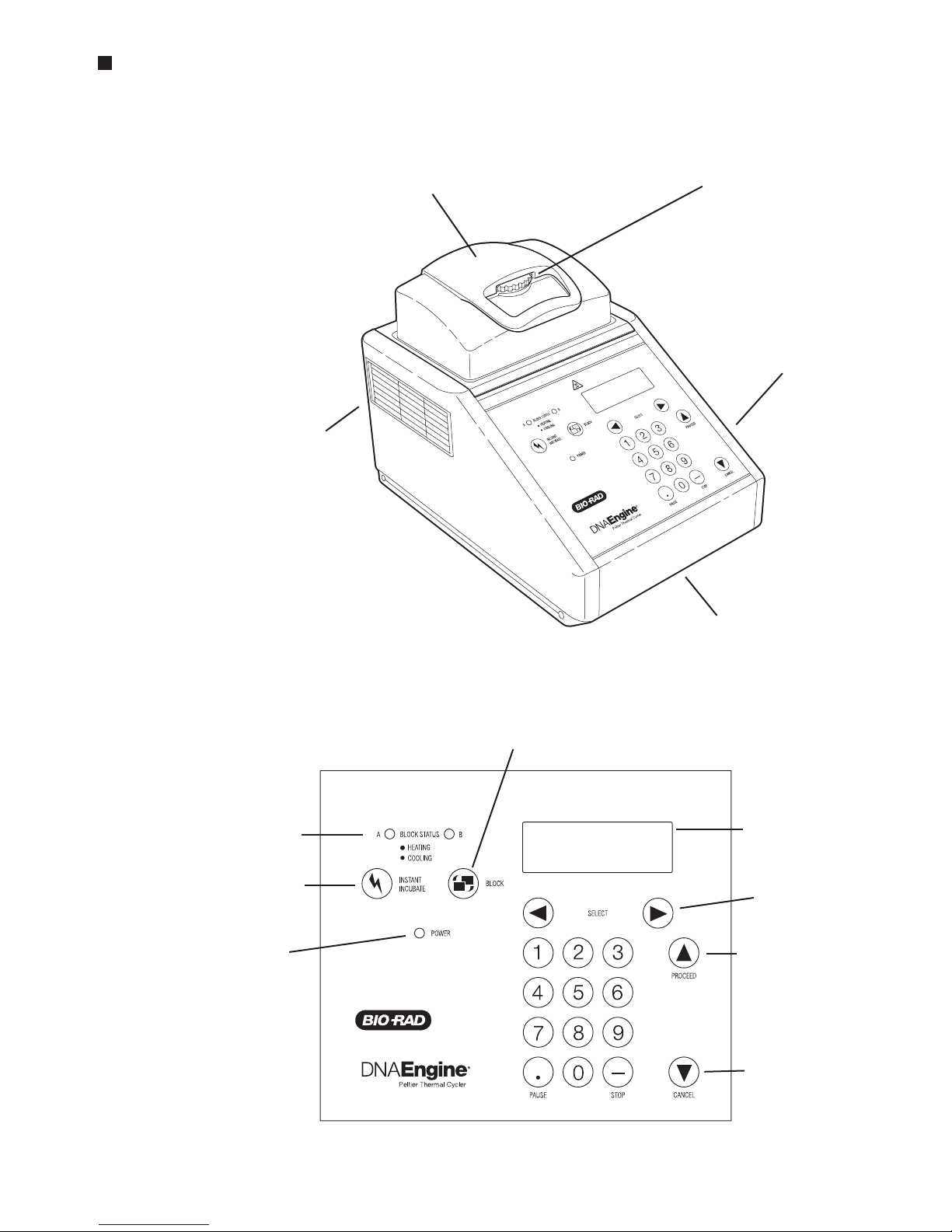
Front View
(Figure 2-1)
Control Panel
(Figure 2-2)
DNA Engine Operations Manual
2-2 Tech Support: 1-800-4BIORAD • 1-800-424-6723 • www.bio-rad.com
Alpha™unit, lid closed
Thumbwheel
Air intake vents
Control panel
Air exhaust vents
(also on other side)
Block status lights
Instant incubation key
Power light
Block key
LCD window
Left and right
selection keys
Proceed key
Cancel key
Layout and Specifications
Tech Support: 1-800-4BIORAD • 1-800-424-6723 • www.bio-rad.com 2-3
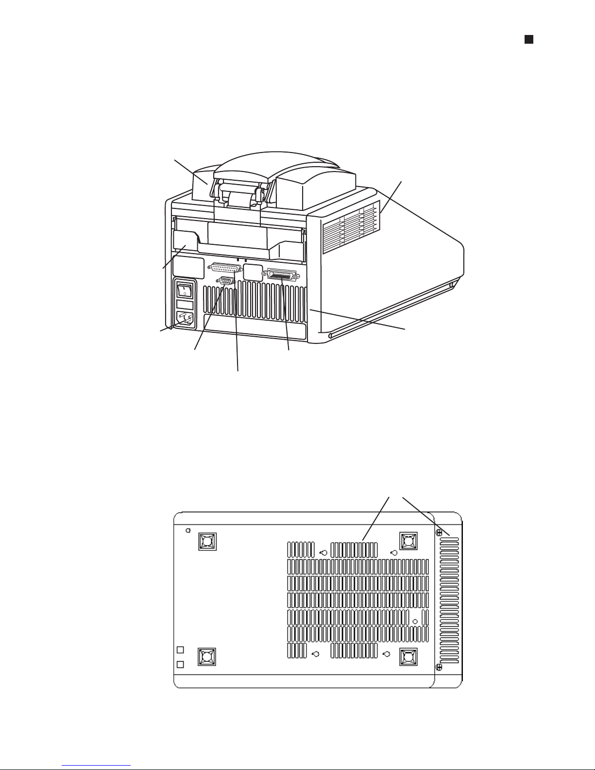
Back View
(Figure 2-3)
Bottom View
(Figure 2-4)
Air exhaust vents
(also on other side)
Alpha unit
Air intake vents
Alpha unit handle
Power cord jack
RS-232 port IEEE-488 port
Parallel printer port
Back
Front
Air intake vents
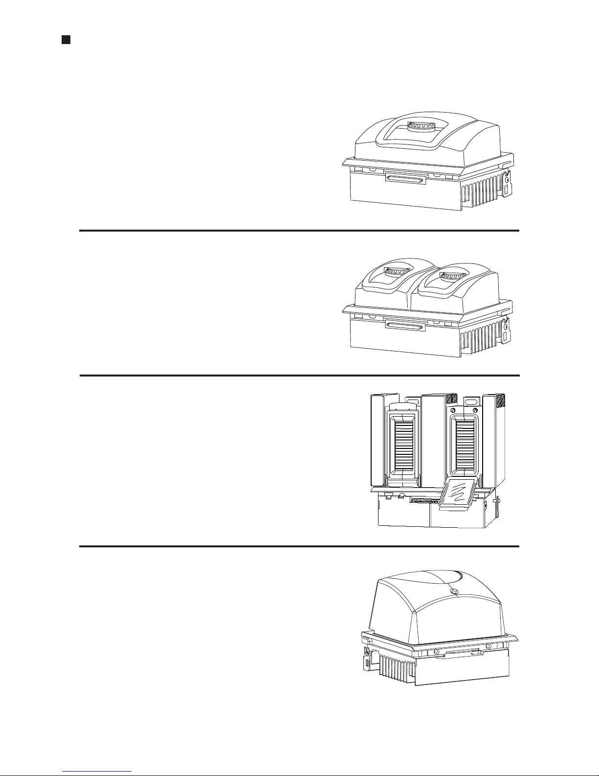
Alpha Units
Single-Block Models
60V Alpha unit: Holds 60 x 0.5 ml tubes
96V Alpha unit: Holds 96 x 0.2 ml tubes or
one 96-well microplate
384 Alpha unit: Holds one 384-well
microplate or one 96-well
microplate
Dual-Block Models
30/30 Dual Alpha
™
Holds 2 x 30 x 0.5
unit: ml tubes
30/48 Dual Alpha unit: Holds 1 x 30 x 0.5 ml
tubes and 1 x 48 x
0.2 ml tubes
48/48 Dual Alpha unit: Holds 2 x 48 x 0.2 ml
tubes or half plates
Slide Block
Slide Chambers™Alpha unit: Holds 2 x 16
standard slides
Moto Alpha™unit
Permits remote control of Alpha unit lid opening;
available in 96-well, 384-well, and flat-block
formats.
DNA Engine Operations Manual
2-4 Tech Support: 1-800-4BIORAD • 1-800-424-6723 • www.bio-rad.com

Layout and Specifications
Tech Support: 1-800-4BIORAD • 1-800-424-6723 • www.bio-rad.com 2-5
Specifications
Thermal range: –5° to 105°C, but no more than 30°C below ambient
temperature (4° to 100°C for the Slide Chambers Alpha unit)
Thermal accuracy: ±0.3°C of programmed target at 90°C, NIST-traceable
Thermal uniformity: ±0.4°C well-to-well within 30 seconds of arrival at 90°C
(for most Alpha units; see specifications for individual
Alpha units)
Ramping speed: Up to 3°C/sec for all single- and dual-block Alpha units;
up to 1.2°C/sec for the Slide Chambers Alpha unit.
Sample capacity: Varies with installed Alpha unit
Line voltage: DNA Engine
®
cycler: 100–240 VAC rms (no adjustment
needed among voltages within these ranges)
Frequency: 50–60 Hz single phase
Power: DNA Engine cycler: 850 W maximum
Fuses: Two 6.3 A, 250 V, 5 x 20 mm
Displays: One 20 x 4 LCD alphanumeric display
Ports: One 25-pin 8-bit parallel interface printer port
One 9-pin RS-232 serial port for printer or remote use
One IEEE-488 bidirectional general purpose interface bus
Memory: 400 typical programs in up to 12 individual folders

DNA Engine Operations Manual
2-6 Tech Support: 1-800-4BIORAD • 1-800-424-6723 • www.bio-rad.com
Gradient Specifications (96V Alpha module only)
Accuracy: +0.3°C of programmed target at end columns, 30
seconds after the timer starts for the gradient step,
NIST–traceable
Column uniformity: +0.4°C, well–to–well within column, within 30
seconds of reaching target temperature
Gradient calculator accuracy: +0.4°C of actual well temperature
Lowest programmable temp: 30°C
Highest programmable temp: 105°C

3-1
Installation
3
Packing Checklist . . . . . . . . . . . . . . . . . . . . . . . . . . . . . . . . . . . . . . . . . . . . . . . . . . . . . . .3-2
Setting Up the DNA Engine Cycler . . . . . . . . . . . . . . . . . . . . . . . . . . . . . . . . . . . . . . . . .3-2
Environmental Requirements . . . . . . . . . . . . . . . . . . . . . . . . . . . . . . . . . . . . . . . . . . . . . .3-2
Power Supply Requirements . . . . . . . . . . . . . . . . . . . . . . . . . . . . . . . . . . . . . . . . . . . . . .3-3
Air Supply Requirements . . . . . . . . . . . . . . . . . . . . . . . . . . . . . . . . . . . . . . . . . . . . . . . . .3-3
Ensuring an Adequate Air Supply . . . . . . . . . . . . . . . . . . . . . . . . . . . . . . . . . . . . . .3-3
Ensuring That Air Is Cool Enough . . . . . . . . . . . . . . . . . . . . . . . . . . . . . . . . . . . . . .3-4
Requirements for Robotics Installations . . . . . . . . . . . . . . . . . . . . . . . . . . . . . . . . . . . .3-4

DNA Engine Operations Manual
3-2 Tech Support: 1-800-4BIORAD • 1-800-424-6723 • www.bio-rad.com
Packing Checklist
After unpacking the DNA Engine®cycler, check to see that you have received the following:
• One DNA Engine base
• One Alpha
™
unit (more if additional units were ordered)
• Two spare fuses
• One power cord
• DNA Engine Peltier Thermal Cycler, Operations Manual (this document)
If any of these components are missing or damaged, contact Bio-Rad or the authorized distributor from whom you purchased the DNA Engine cycler to obtain a replacement. Please
save the original packing materials in case you need to return the DNA Engine cycler for
service. See appendix A for warranty information.
Setting Up the DNA Engine Cycler
The DNA Engine cycler requires only minimal assembly: plugging in the power cord and
inserting an Alpha unit. Insert the power cord plug into its jack at the back of the machine
(see fig. 2-3 for location of jack), then plug the cord into an electrical outlet. With the
machine turned off, insert an Alpha unit (see “Installing an Alpha Unit,” chapter 4).
Caution: Do not insert or remove an Alpha unit with the DNA Engine cycler
turned on; electrical arcing can result. Read the safety warning at
the front of this manual regarding electrical safety when inserting or
removing an Alpha unit.
Environmental Requirements
Ensure that the area where the DNA Engine cycler is installed meets the following
conditions, for reasons of safety and performance:
• Nonexplosive environment
• Normal air pressure (altitude below 2000 m)
• Ambient temperature 5–31°C
• Relative humidity up to 90%
• Unobstructed access to air that is 31°C or cooler (see below)

Installation
Tech Support: 1-800-4BIORAD • 1-800-424-6723 • www.bio-rad.com 3-3
• Protection from excessive heat and accidental spills (Do not place the DNA Engine
cycler near such heat sources as radiators, and protect it from danger of having
water or other fluids splashed on it, which can cause shorting in its electrical circuits.)
Power Supply Requirements
The DNA Engine cycler requires 100–240 VAC, 50–60 Hz, and a grounded outlet. The DNA
Engine cycler can use current in the specified range without adjustment, so there is no
voltage-setting switch.
Power cords for outlets other than the US 120V outlet may be purchased from computer
stores, since they are also used for most desktop computers and printers and meet
international standard IEC-320. The power cord must be rated to carry at least 10 A at
125 V or 250 V, depending on the voltage available in your nation. The quality of the
power cord can be further ensured by making certain it is inscribed with the trademark
of UL, CSA, TUV, VDE, or another national testing agency.
Note: Do not cut the supplied 120 V power cord and attach a different connector.
Use a one-piece molded connector of the type specified above.
Air Supply Requirements
The DNA Engine cycler requires a constant supply of air that is 31°C or cooler in order
to remove heat from the Alpha unit’s heat sink. Air is taken in from vents at the front,
back, and bottom of the machine and exhausted from vents on both sides (see figs. 21, 2-3, and 2-4). If the air supply is inadequate or too hot, the machine can overheat,
causing performance problems, software error messages (particularly “HS Overheating”
and “Slow Block Cycling”), and even automatic shutdowns. Special attention should be
paid to airflow and air temperature in robotics installations of DNA Engine cyclers.
Ensuring an Adequate Air Supply
• Do not block the air intake vents.
Position the DNA Engine cycler at least 10 cm from vertical surfaces and other thermal
cyclers (greater distances may be required; see below). Do not put loose papers under
the machine; they can be sucked into the air intake vents on the bottom of the machine.
• Do not allow dust or debris to collect in the air intake vents.
The bottom air vents are particularly liable to collect dust and debris, sometimes
completely clogging up. Check for dust and debris every few months, and clean the
intake vents as needed. Remove light collections of dust with a soft-bristle brush or damp
cloth. Severe collections of dust and debris should be vacuumed out. Turn the machine
off prior to cleaning or vacuuming air vents.

DNA Engine Operations Manual
3-4 Tech Support: 1-800-4BIORAD • 1-800-424-6723 • www.bio-rad.com
Ensuring That Air Is Cool Enough
• Do not position two or more DNA Engine cyclers (or other thermal cyclers) so that
the hot exhaust air of one blows directly into the air intake vents of another.
• Make sure the DNA Engine cycler receives air that is 31°C or cooler by measuring
the temperature of air entering the machine through its air intake vents.
Place the DNA Engine cycler where you plan to use it, and turn it on. Try to reproduce
what will be typical operating conditions for the machine in that location, particularly
any heat-producing factors (e.g., nearby equipment running, window blinds open,
lights on). Run a typical protocol (e.g., 2-Step) for 30 minutes to warm up the DNA
Engine cycler, then measure the air temperature at the back air intake vents. If more
than one machine is involved, measure the air temperature for each.
If the air intake temperature of any machine is warmer than 31°C, use table 3-1 to
troubleshoot the problem. Some experimentation may be required to determine the
best solution when more than one cause is involved. After taking steps to solve the
problem, verify that the temperature of the air entering the air intake vents has been
lowered, using the procedure outlined above.
Requirements for Robotics Installations
Robotics installations require special attention to airflow and air temperature. Typically in
these installations, DNA Engine cyclers and other thermal cyclers are crowded into a
small area, along with other heat-generating equipment. Overheating can quickly occur
when many of these machines are operating at once, unless preventive measures are
taken.
Follow the procedures described above to ensure adequate airflow and an air intake
temperature of 31°C or cooler. Air intake temperature must be verified by measurement.
Do not use oil to thermally couple sample vessels to the blocks of machines in a robotics
installation. Oil makes plates difficult to remove.
Table 3-1 Troubleshooting Air Supply Problems
Cause Possible Remedies
Air circulation is poor. Provide more space around machine or adjacent room ventilation.
Ambient air temperature is
high.
Adjust air conditioning to lower ambient air temperature.
Machine is in warm part of
room.
Move machine away from, or protect machine from, such heat
sources as radiators, heaters, other equipment, or bright sunlight.
Machines are crowded.
Arrange machines so that warm exhaust air does not enter intake
vents.

4-1
Operation
4
Turning the DNA Engine Cycler On . . . . . . . . . . . . . . . . . . . . . . . . . . . . . . . . . . . . . . . . .4-2
Understanding the Main Menu . . . . . . . . . . . . . . . . . . . . . . . . . . . . . . . . . . . . . . . . . . . .4-2
Using the Control Panel . . . . . . . . . . . . . . . . . . . . . . . . . . . . . . . . . . . . . . . . . . . . . . . . .4-3
Operation Keys . . . . . . . . . . . . . . . . . . . . . . . . . . . . . . . . . . . . . . . . . . . . . . . . . . . .4-3
Status Indicator Lights . . . . . . . . . . . . . . . . . . . . . . . . . . . . . . . . . . . . . . . . . . . . . .4-3
Using the Data Ports . . . . . . . . . . . . . . . . . . . . . . . . . . . . . . . . . . . . . . . . . . . . . . . . . . . .4-3
Operating Alpha Units . . . . . . . . . . . . . . . . . . . . . . . . . . . . . . . . . . . . . . . . . . . . . . . . . . .4-4
Installing an Alpha Unit . . . . . . . . . . . . . . . . . . . . . . . . . . . . . . . . . . . . . . . . . . . . . .4-4
Removing an Alpha Unit . . . . . . . . . . . . . . . . . . . . . . . . . . . . . . . . . . . . . . . . . . . . .4-5
Opening an Alpha Unit . . . . . . . . . . . . . . . . . . . . . . . . . . . . . . . . . . . . . . . . . . . . . .4-5
Closing an Alpha Unit . . . . . . . . . . . . . . . . . . . . . . . . . . . . . . . . . . . . . . . . . . . . . . .4-5
Selecting the Correct Sample Vessel . . . . . . . . . . . . . . . . . . . . . . . . . . . . . . . . . . . . . . .4-6
0.5ml Tubes . . . . . . . . . . . . . . . . . . . . . . . . . . . . . . . . . . . . . . . . . . . . . . . . . . . . . . .4-6
0.2ml Tubes . . . . . . . . . . . . . . . . . . . . . . . . . . . . . . . . . . . . . . . . . . . . . . . . . . . . . . .4-6
Microplates . . . . . . . . . . . . . . . . . . . . . . . . . . . . . . . . . . . . . . . . . . . . . . . . . . . . . . .4-6
Thin-Walled Vs. Thick-Walled Tubes . . . . . . . . . . . . . . . . . . . . . . . . . . . . . . . . . . . .4-6
Sealing Sample Vessels . . . . . . . . . . . . . . . . . . . . . . . . . . . . . . . . . . . . . . . . . . . . . . . . . .4-7
Sealing with Oil or Wax . . . . . . . . . . . . . . . . . . . . . . . . . . . . . . . . . . . . . . . . . . . . . .4-7
Sealing with the Hot Bonnet Lid . . . . . . . . . . . . . . . . . . . . . . . . . . . . . . . . . . . . . . .4-7
Adjusting the Hot Bonnet Lid’s Pressure . . . . . . . . . . . . . . . . . . . . . . . . . . . . . . . .4-8
Loading Sample Vessels into the Block . . . . . . . . . . . . . . . . . . . . . . . . . . . . . . . . . . . . .4-9
Using Oil to Thermally Couple Sample Vessels to the Block . . . . . . . . . . . . . . . .4-10
Appendix 4-A: Tube, Microplate, and Sealing System Selection Chart . . . . . . . . . . .4-11
Appendix 4-B: Safety Warning Regarding Use of
35
S Nucleotides . . . . . . . . . . . . . .4-12

DNA Engine Operations Manual
4-2 Tech Support: 1-800-4BIORAD • 1-800-424-6723 • www.bio-rad.com
Turning the DNA Engine®Cycler On
Move the power switch to “1” (the “On” position). The fan will turn on and the power light
on the keyboard will glow red. In most cases a self-test of the heat pumps will begin
running (see note below). Its progress is tracked on a screen in the LCD window:
This screen disappears in 1 minute. If a problem is detected, the display shows an error
message.
Note: If the Alpha
™
unit’s block or heat sink is not at ambient temperature (typically
because the Alpha unit was recently in use), the machine will skip the self-test.
If the self-test does not detect any problems, the Main Menu is displayed:
The DNA Engine cycler is now ready to execute programs.
Understanding the Main Menu
The Main Menu is the common access point to all programming and machine configuration
screens.
• Run: Executes a program.
• Enter: Allows new programs to be entered.
• List: Accesses utilities that display or print a program’s steps.
• Edit: Allows modification of stored programs.
• Files: Accesses file management utilities.
• Setup: Accesses machine and networking configuration screens.
PTC-200:
Self testing
.
PTC-200:
_RUN Enter
List Edit
Files Setup

Operation
Tech Support: 1-800-4BIORAD • 1-800-424-6723 • www.bio-rad.com 4-3
Using the Control Panel
The control panel (see fig. 2-2) includes operation keys, status indicator lights, an LCD
window for displaying programming and machine status text, and a numeric keypad
for entering values into programs.
Operation Keys
• Select keys (left and right arrows): Move the cursor one space or option to the left or
right in the LCD window; during a protocol run, display time and cycle information.
• Proceed: Accepts a selected menu or screen option; during a protocol run, advances
the program to its next step.
• Cancel: Terminates a running protocol; during program creation or editing, cancels
the last entry.
• Stop: Terminates a running protocol.
• Pause: Pauses a protocol during execution; accesses Japanese Katakana syllabary.
• Instant Incubate: Initiates a program that sets up the DNA Engine cycler as a
simple incubator.
• Block: Selects a different block when using a Dual Alpha
™
unit; switches between
block screens and the Main Menu in the LCD window during a protocol run.
Status Indicator Lights
• Power light: Glows red when the DNA Engine cycler is powered up.
• Block Status lights: Indicate which blocks are in use; glow red when blocks are
heating and green when blocks are cooling.
Using the Data Ports
The DNA Engine cycler has three data ports located at the rear of the machine: an RS232 port, an IEEE-488 port, and a parallel (printer) port. See chapters 8 and 9 for
information on using these ports to network machines, connect them to a computer, or
print data.
DNA Engine Operations Manual
4-4 Tech Support: 1-800-4BIORAD • 1-800-424-6723 • www.bio-rad.com
Operating Alpha Units
Note: Operation of the Slide Chambers™Alpha unit will not be discussed, owing to
the many differences between this type of Alpha unit and the others. Please see the
Slide Chambers Operations Manual for operating instructions.
Note: Moto Alpha™units are installed and removed as described below. See the
Moto Alpha Unit Operations Manual for instructions on opening and closing Moto
Alpha units.
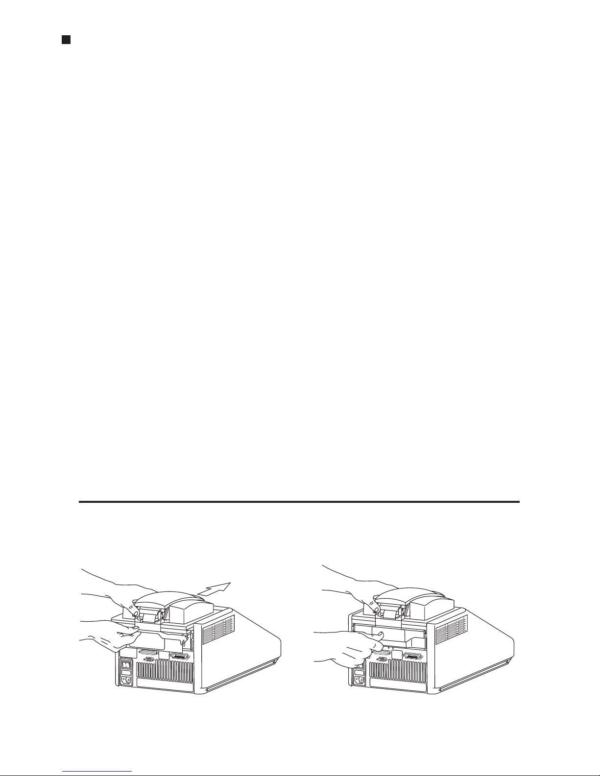
Installing an Alpha Unit
1. Turn the DNA Engine cycler off (see the Caution on p. 4-5).
2. Hold the Alpha unit at its front and back edges.
3. Lower the Alpha unit into the DNA Engine base, leaving at least 3cm between the
front edge of the Alpha unit and the front of the base.
4. Raise the handle at the back of the Alpha unit, and slide the block forward as far
as it will go (fig. 4-1A).
5. Push the handle down until it is completely vertical (fig. 4-1B); firm pressure may
be required. A definite click signals that the Alpha unit’s connectors have mated
with the DNA Engine cycler’s connectors.
When the handle is in the down position, the Alpha unit is locked into place.
Figure 4-1 Installing an Alpha unit.
A
B
Operation
Tech Support: 1-800-4BIORAD • 1-800-424-6723 • www.bio-rad.com 4-5
Removing an Alpha Unit
1. Turn the DNA Engine cycler off (see the Caution below).
2. Pull upward on the handle. When the lock releases, you will hear a click, and the
Alpha unit will slide a little toward the back of the DNA Engine cycler. The electrical connectors of the Alpha unit and the DNA Engine cycler are now
disengaged, so there is no danger of electrical shock.
3. Slide the Alpha unit toward the rear of the DNA Engine cycler about 3 cm.
4. Grasp the front and back edges of the Alpha unit, and lift it out of the machine.
Caution: Do not insert or remove an Alpha unit with the DNA Engine
cycler turned on; electrical arcing can result. Read the safety
warning at the front of this manual regarding electrical safety
when inserting or removing an Alpha unit.
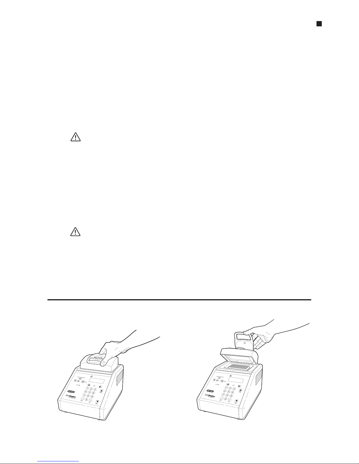
Opening an Alpha Unit
Grip the front edge of the top lever of the Hot Bonnet®lid as shown in figure 4-2A,
and pull upward firmly. The top lever will pop open to reveal the entire thumbwheel
(fig. 4-2B). Continue pulling upward to open the Hot Bonnet lid. The Hot Bonnet lid
will tip backward, revealing the entire block.
Caution: Do not pull on the thumbwheel to open the unit. This can
damage the Hot Bonnet lid’s closing mechanism.
Closing an Alpha Unit
Press down on the top lever. The lever will close down over the thumbwheel as the
Hot Bonnet lid closes down over the sample block. A click signifies that the
Hot Bonnet lid’s latch has engaged.
Figure 4-2 Opening an Alpha unit.
A
B

DNA Engine Operations Manual
4-6 Tech Support: 1-800-4BIORAD • 1-800-424-6723 • www.bio-rad.com
Selecting the Correct Sample Vessel
The DNA Engine cycler’s wide variety of interchangeable Alpha units affords you great
scope in choosing sample vessels. Keep in mind that differences in tube and plate composition and wall thickness among the many brands available can affect reaction
performance. Protocols may require some adjustment to ensure optimum performance
when using a new vessel type. Bio-Rad offers a full range of tubes and microplates, manufactured to the specifications of each type of Alpha unit to ensure a precise fit. See
chapter appendix 4-A for a complete list.
0.5 ml Tubes
Make sure thick-walled 0.5 ml tubes fit the wells snugly. Since these tubes were originally
designed for centrifuges, some brands may not fit tightly in thermal cycler wells. Thin-walled
0.5 ml tubes were specifically designed for thermal cycling, and the higher quality brands
provide a good and consistent fit. Bio-Rad provides thin- and thick-walled 0.5 ml tubes
designed for precise block fit.
0.2 ml Tubes
All types of thin-walled 0.2 ml tubes may be used. Bio-Rad sells high-quality 0.2 ml
tubes in a number of styles, including individual tubes and strips.
Microplates
A variety of 96-well polycarbonate or polypropylene microplates can be used in 96-well
Alpha units as long as they fit the wells snugly. Polypropylene microplates are usually
preferred because they exhibit very low protein binding and, unlike polycarbonate
microplates, do not lose water vapor through the vessel walls. This allows smaller
sample volumes to be used — as little as 5–10 µl. Polypropylene microplates and compatible sealing systems are available from Bio-Rad. (See “Sealing Sample Vessels” on
the next page for a description of available sealing systems from Bio-Rad.)
Thin-Walled Vs. Thick-Walled Tubes
The thickness of sample tubes directly affects the speed of sample heating and thus
the amount of time required for incubations. Thick-walled tubes delay sample heating,
since heat transfers more slowly through the tubes’ walls. For the earliest types of
thermal cyclers this delay mattered little. These machines’ ramping rates were so slow
(below 1°C/sec) that there was plenty of time for heat to transfer through the tube wall
to the sample, during a given incubation.
Modern thermal cyclers have much faster ramping rates (up to 2–3°C/sec), so the faster
heat transfer provided by thin-walled tubes allows protocols to be significantly shortened. On average, about 30 seconds can be saved per cycle by using thin-walled
tubes, for an overall savings of 15 minutes in a 30-cycle run.

Operation
Tech Support: 1-800-4BIORAD • 1-800-424-6723 • www.bio-rad.com 4-7
Sealing Sample Vessels
To avoid changing the concentration of reactants, steps must be taken to prevent the
evaporation of water from reaction mixtures during thermal cycling. Only a layer of oil
or wax will completely prevent evaporation from the surface of the reaction fluid.
However, an adequate degree of protection can be achieved by sealing vessels with
caps, film, adhesive seals, or mats, then cycling the samples using the heated lid to
prevent condensation.
Sealing with Oil or Wax
Mineral oil, silicone oil, paraffin wax, or Chill-out™liquid wax may be used to seal samples.
Use only a small amount of oil or wax; 1–3 drops (15–50µl) are usually sufficient. (Include
this volume in the total volume when setting up a calculated-control protocol; see
“Choosing a Temperature Control Mode” in Chapter 5.) Use the same amount of oil or
wax in all sample vessels to ensure a uniform thermal profile.
Most paraffin waxes solidify at room temperature. The wax can then be pierced with a
micropipette and the samples drawn off from below the wax. Silicone oil and mineral oil
can be poured off or aspirated from tubes if the samples are first frozen (–15° to –20°C).
The samples are usually pure enough for analysis without an extraction.
Chill-out liquid wax (available from Bio-Rad) is an easy-to-use alternative to oil. This purified paraffinic oil solidifies at 10°C and is liquid at room temperature. By programming a
hold at low temperature, the wax can be solidified at the end of a run. A pipette tip can
then be used to pierce the wax in the tubes and remove the samples. The wax is available
in a clear, optical-assay grade or dyed red to assist in monitoring its use. The red dye has
no adverse effects on fluorescent gel analysis of reaction products.
Sealing with the Hot Bonnet Lid
The Hot Bonnet lid’s heated inner surface maintains the air in the upper part of
sample vessels at a higher temperature than the reaction mixture. This prevents condensation of evaporated water vapor onto the vessel walls and lid, so that solution
concentrations are unchanged by thermal cycling. The Hot Bonnet lid also exerts
pressure on the tops of vessels loaded into the block, helping to maintain a vaportight seal and to firmly seat tubes or the plate in the block.
Caps, film, adhesive seals, or mats must be used along with the Hot Bonnet lid to prevent
evaporative losses.
Note: When tubes are cooled to below-ambient temperatures, a ring of condensation
may form in tubes above the liquid level but below the top of the sample block. This
is not a cause for concern since it occurs only at the final cool-down step, when
thermal cycling is complete.

DNA Engine Operations Manual
4-8 Tech Support: 1-800-4BIORAD • 1-800-424-6723 • www.bio-rad.com
Microseal®‘A’ film offers a quick alternative to sealing microplates or arrays of tube
strips. This film is specially designed to seal tightly during cycling, yet release smoothly
to minimize the risk of aerosol formation and cross-contamination of samples.
Microseal ‘A’ film is easily cut for use with fewer than 96 samples.
Microseal ‘B’ adhesive seals feature an aggressive adhesive, effective from –20°C to
110°C, which allows secure sample storage or transport before and after cycling. The
clear polyester backing allows easy inspection of sample wells. Microseal ‘B’ clear,
adhesive seals are ideal for thermal cycling in all polypropylene and polystyrene
microplates.
Microseal ‘F’ aluminized foil acts as a barrier against evaporation from –20°C to 105°C.
It is thin enough to pierce with a pipet tip for recovery of sample from individual wells.
96-well PCR plate sealing mats (223-9442) are an economical means to seal 96-well
microplates. An array of 96 dimples on the mat helps orient it on the microplate and prevents the mat from sticking to the heated lid. The mats may be cleaned with sodium
hypochlorite (bleach) for reuse, and they are autoclavable.
Microseal ‘P’/’P+’ pads are designed for use in applications such as cycle sequencing, in
which several successive runs may be sealed with the same pad. Use ‘P’ pads with the
original version of Power Bonnet
™
lids (ALP-1296 and ALP-1238) and use ‘P+’ pads with
the newer-design Moto Alpha
™
units (ALP-2296, ALP- 2238, ALP-2200, and ALP-2201).
Adjusting the Hot Bonnet Lid’s Pressure
The pressure exerted by the inner lid of the Hot Bonnet lid must be manually adjusted
to fit the sample vessels being used in a given reaction. Once set, the Hot Bonnet lid
can be opened and closed repeatedly without readjustment as long as neither the
tube or microplate type nor the sealing method changes. Any change in vessel type
or sealing method requires readjustment of the Hot Bonnet lid.
Follow these steps to adjust the pressure exerted by the Hot Bonnet inner lid:
1. Make sure the block’s wells are clean. Even tiny amounts of extraneous material
can interfere with the proper seating of a microplate or tubes, which would prevent
the inner lid from exerting uniform pressure on the loaded microplate or tubes.
2. Open the Hot Bonnet lid. Turn the green thumbwheel all the way counterclockwise to completely raise the inner lid.
3. Load either a microplate or at least eight individual tubes into the sample block. The
inner lid pivots around a central point, so it is important to distribute individual tubes
evenly. Load at least four tubes in the center of the block and at least one tube in
each of the four corners of the block. If using a sealing film or mat, apply it to the
loaded microplate according to the manufacturer’s directions.

Operation
Tech Support: 1-800-4BIORAD • 1-800-424-6723 • www.bio-rad.com 4-9
4. Close the Hot Bonnet lid by pressing down on the top lever. Turn the thumbwheel
clockwise to lower the Hot Bonnet inner lid onto the loaded microplate/tubes. The
thumbwheel turns easily at first since the inner lid has not yet come into contact
with anything. Stop turning the thumbwheel when you feel increased resistance,
which indicates that the inner lid has touched the microplate/tubes.
5. Open the Hot Bonnet lid. Turn the thumbwheel clockwise an extra half to three-quarters of a turn to set an appropriate lid pressure.
Caution: Do not turn the thumbwheel more than three-quarters of a
turn. This can make it hard or impossible to close the lid and
puts excessive strain on the latch holding the lid closed.
An extra half to three-quarters of a turn ensures the correct pressure for most types of
reaction vessels. Some empirical testing may be required to determine the optimum
pressure required for certain vessels. Once this pressure has been determined, the
thumbwheel position that delivers it may be marked with a colored marking pen or
piece of tape.
Note: As an aid in gauging how much the thumbwheel has been turned, mark it at
the quarter turn positions, or every sixth bump on the thumbwheel (there are 24 total
bumps).
6. Close the Hot Bonnet lid.
Loading Sample Vessels into the Block
When using a small number of tubes, they should all be placed in the center of the block,
to ensure uniform thermal cycling of all samples. Also load at least one empty tube in
each corner of the block, to ensure that the Hot Bonnet lid exerts even pressure on the
sample tubes (see “Adjusting the Hot Bonnet Lid Pressure,” above).
To ensure uniform heating and cooling of samples, sample vessels must be in complete
contact with the block. Adequate contact is ensured by always doing the following:
• Ensure that the block is clean before loading samples. (See chapter 10 for
cleaning instructions.)
• Firmly press individual tubes or the microplate into the block wells.
 Loading...