


MJ Mini™Gradient Thermal Cycler
Operations Manual
PTC-1148 MJ Mini Thermal Cycler

i
MJ Mini™Gradient Thermal Cycler
Operations Manual
PTC-1148 MJ Mini Thermal Cycler

MJ Mini Gradient Thermal Cycler Operations Manual
ii
Copyright ©2005, Bio-Rad Laboratories, Incorporated. Reproduction in any form, either print or electronic, is prohibited without written permission of Bio-Rad Laboratories, Inc.
Chill-Out, Hot Bonnet, Microseal, MiniCycler, MJ Mini, MJ Research, Mini Opticon and the helix logo
are trademarks belonging to Bio-Rad Laboratories, Inc.
NOTICE TO PURCHASER
Purchase of this instrument, Serial No. ____________, conveys a limited non-transferable immunity from
suit for the purchaser’s own internal research and development and for use in applied fields other than
Human In Vitro Diagnostics under one or more of U.S. Patents Nos. 5,656,493, 5,333,675, 5,475,610
(claims 1, 44, 158, 160-163 and 167 only), and 6,703,236 (claims 1-7 only), or corresponding claims in
their non-U.S. counterparts, owned by Applera Corporation. No right is conveyed expressly, by implication or by estoppel under any other patent claim, such as claims to apparatus, reagents, kits, or
methods such as 5’ nuclease methods. Further information on purchasing licenses may be obtained
by contacting the Director of Licensing, Applied Biosystems, 850 Lincoln Centre Drive, Foster City,
California 94404, USA.
This MJ Mini thermal cycler, when combined with a MiniOpticon detection module bearing a valid label
license under U.S. Patent No. 6,814,934, constitutes a real-time thermal cycler licensed under U.S.
Patent No. 6,814,934 and corresponding claims in any Canadian counterpart patent thereof owned by
Applera Corporation, for use solely in research and all applied fields except human and veterinary in
vitro diagnostics, provided that the real-time thermal cycler royalty fee that is applicable to said thermal
cycler has been paid. No rights are conveyed expressly, by implication or estoppel to any patents on
real-time methods, including but not limited to 5' nuclease assays, or to any patent claiming a reagent
or kit. For further information on purchasing license rights, contact the Director of Licensing at Applied
Biosystems, 850 Lincoln Centre Drive, Foster City, California, 94404, USA.
10968 rev D

iii
Table of Contents
Explanation of Symbols . . . . . . . . . . . . . . . . . . . . . . . . . . . . . . . . . . . . . . . . . . . . . . . . .iv
Safety Warnings and Guidelines . . . . . . . . . . . . . . . . . . . . . . . . . . . . . . . . . . . . . . . . . . .iv
Electromagnetic Interference and FCC Warning . . . . . . . . . . . . . . . . . . . . . . . . . . . . . . .v
Documentation Conventions . . . . . . . . . . . . . . . . . . . . . . . . . . . . . . . . . . . . . . . . . . . . .vi
1. Introduction . . . . . . . . . . . . . . . . . . . . . . . . . . . . . . . . . . . . . . . . . . . . . . . . . . . . . .1-1
2. Layout and Specifications . . . . . . . . . . . . . . . . . . . . . . . . . . . . . . . . . . . . . . . . . .2-1
3. Installation . . . . . . . . . . . . . . . . . . . . . . . . . . . . . . . . . . . . . . . . . . . . . . . . . . . . . . .3-1
4. Operation . . . . . . . . . . . . . . . . . . . . . . . . . . . . . . . . . . . . . . . . . . . . . . . . . . . . . . . .4-1
5. Running Protocols . . . . . . . . . . . . . . . . . . . . . . . . . . . . . . . . . . . . . . . . . . . . . . . .5-1
6. Creating Programs . . . . . . . . . . . . . . . . . . . . . . . . . . . . . . . . . . . . . . . . . . . . . . . . .6-1
7. Editing Programs . . . . . . . . . . . . . . . . . . . . . . . . . . . . . . . . . . . . . . . . . . . . . . . . . .7-1
8. Using the Utilities . . . . . . . . . . . . . . . . . . . . . . . . . . . . . . . . . . . . . . . . . . . . . . . . .8-1
9. Maintenance . . . . . . . . . . . . . . . . . . . . . . . . . . . . . . . . . . . . . . . . . . . . . . . . . . . . . .9-1
10. Troubleshooting . . . . . . . . . . . . . . . . . . . . . . . . . . . . . . . . . . . . . . . . . . . . . . . . . .10-1
Appendix A: Warranties . . . . . . . . . . . . . . . . . . . . . . . . . . . . . . . . . . . . . . . . . . . . . . .A-1
Appendix B: Factory-Installed Protocols . . . . . . . . . . . . . . . . . . . . . . . . . . . . . . . . .B-1
Index . . . . . . . . . . . . . . . . . . . . . . . . . . . . . . . . . . . . . . . . . . . . . . . . . . . . . . . . . . . . . .In-1
Declaration of Conformity . . . . . . . . . . . . . . . . . . . . . . . . . . . . . . . . . . . . . . . . . .DoC-1
MJ Mini Gradient Thermal Cycler Operations Manual
iv
Explanation of Symbols
CAUTION: Risk of Danger! Wherever this symbol appears, always consult note in
this manual for further information before proceeding. This symbol identifies components that pose a risk of personal injury or damage to the instrument if improperly
handled.
CAUTION: Risk of Electrical Shock! This symbol identifies components that pose a
risk of electrical shock if improperly handled.
CAUTION: Hot Surface! This symbol identifies components that pose a risk of personal injury due to excessive heat if improperly handled.
Safety Warnings
Warning: Operating the MJ Mini Peltier thermal cycler before reading this manual
can constitute a personal injury hazard. Only qualified laboratory personnel trained
in the safe use of electrical equipment should operate this machine.
Warning: Do not open or attempt to repair the MJ Mini cycler base, the power
supply, the heat pump/sample block, or other accessory. Doing so will void your warranties and can put you at risk for electrical shock. Return the MJ Mini cycler to the
factory (US customers) or an authorized distributor (all other customers) if repairs are
needed.
Warning: The sample blocks can become hot enough during the course of normal
operation to cause burns or cause liquids to boil explosively. Wear safety goggles or
other eye protection at all times during operation.
Warning: The MJ Mini cycler incorporate neutral fusing, which means that live
power may still be available inside the machines even when a fuse has blown or
been removed. Never open the cycler base; you could receive a serious electrical
shock. Opening the base will also void your warranties.
Safe Use Guidelines
The MJ Mini is designed to be safe to operate under the following conditions:
• Indoor use
• Altitude up to 2000 m
• Temperature 5˚C to 40˚C
• Maximum relative humidity 80% for temperatures up to 31˚C, decreasing
linearly to 50% relative humidity at 40˚C
• Mains supply voltage fluctuations not to exceed ±10% of the nominal voltage
• Installation Categories (Overvoltage categories) II
• Pollution degree 2
• Electrical Supply, 100-240 VAC, 50-60 Hz, 400 W

v
Electromagnetic Interference
This device complies with Part 15 of the FCC Rules. Operation is subject to the following two conditions: (1) this device may not cause harmful interference, and (2) this
device must accept any interference received, including interference that may cause
undesired operation.
This device has been tested and found to comply with the EMC standards for emissions and susceptibility established by the European Union at time of manufacture.
This digital apparatus does not exceed the Class A limits for radio noise emissions
from digital apparatus set out in the Radio Interference Regulations of the Canadian
Department of Communications.
LE PRESENT APPAREIL NUMERIQUE N'EMET PAS DE BRUITS RADIOELECTRIQUES DEPASSANT LES LIMITES APPLICABLES AUX APPAREILS
NUMERIQUES DE CLASS A PRESCRITES DANS LE REGLEMENT SUR LE BROUILLAGE RADIOELECTRIQUE EDICTE PAR LE MINISTERE DES COMMUNICATIONS
DU CANADA.
FCC Warning
Warning: Changes or modifications to this unit not expressly approved by the party
responsible for compliance could void the user’s authority to operate the equipment.
Note: This equipment has been tested and found to comply with the limits for a
Class A digital device, pursuant to Part 15 of the FCC Rules. These limits are
designed to provide reasonable protection against harmful interference when the
equipment is operated in a commercial environment. This equipment generates,
uses, and can radiate radiofrequency energy and, if not installed and used in accordance with the instruction manual, may cause harmful interference to radio
communications. Operation of this equipment in a residential area is likely to cause
harmful interference in which case the user will be required to correct the interference at his own expense.
Shielded cables must be used with this unit to ensure compliance with the Class A
FCC limits.
Regarding FCC Compliance: Although this design of instrument has been tested
and found to comply with Part 15, Subpart B of the FCC Rules for a Class A digital
device, please note that this compliance is voluntary, for the instrument qualifies as
an "Exempted device" under 47 CFR § 15.103(c), in regard to the cited FCC regulations in effect at the time of manufacture.

MJ Mini Gradient Thermal Cycler Operations Manual
vi
Documentation Conventions
Documentation Conventions
Typographic Conventions
The names of keyboard keys are encased in double angle brackets:
Example «Proceed»
Items in programming menus are italicized:
Example Select Edit from the Main Menu.
Graphic Conventions
The programming screens displayed in the LCD window can display up to seven
lines of text at one time.
Example
Terminology
A programming option is termed “selected” when the option is highlighted. In this
manual, the selected terms are outlined (see the example above).
New: Lid:100˚C
ABCD Vol: 20µL
1= 92.0˚ FOR 0:30
2=
LOWER TEMP ˚C:

1-1
Introduction
1
Meet the MJ Mini Thermal Cyclers . . . . . . . . . . . . . . . . . . . . . . . . . . . . . . . . . . . . .1-2
Using This Manual . . . . . . . . . . . . . . . . . . . . . . . . . . . . . . . . . . . . . . . . . . . . . . . . . . .1-2
Important Safety Information . . . . . . . . . . . . . . . . . . . . . . . . . . . . . . . . . . . . . . . . . .1-3

MJ Mini Gradient Thermal Cycler Operations Manual
1-2 Tech Support: 1-800-4BIORAD • 1-800-424-6723 • www.bio-rad.com
Meet the MJ Mini Thermal Cyclers
Thank you for purchasing an PTC-1148 MJ Mini thermal cycler. This personal sized
cycler features:
• Premium cycling in a medium capacity cycler: the MJ Mini can hold 48 x 0.2 ml
tubes, 12 x 0.5 ml tubes or one 48-well microplate.
• Ability to program and maintain a 16˚C temperature gradient, front-to-back,
along the block for protocol optimization in a single run.
• Upgradability to a real-time PCR system with the addition of the Mini Opticon™
real-time detector.
• Integrated Hot Bonnet® heated lid for oil-free thermal cycling. The heated lid
pressure may be manually adjusted to permit the seating of different vessels.
• Intuitive software with an easy-to-read interface for rapid input of programs,
which may contain advanced protocol steps such as auto-time extension, auto-temperature increment, and variable ramp rates.
• Choice of calculated sample temperature control for highest speed and accuracy
or block control for compatibility with protocols designed for a variety of instrument
types.
• Space-saving design for easy setup and transportation.
• Instant Incubate feature for continuous-temperature incubations.
• Customizable factory-installed protocols.
Using This Manual
This manual contains all the information you need to operate your MJ Mini thermal
cycler safely and productively:
• Chapter 2 acquaints you with the physical characteristics of this cycler.
• Chapters 3–5 present the basics of installing and operating the MJ Mini cycler.
• Chapters 6 and 7 describe programming.
• Chapter 8 outlines the utilities available on the MJ Mini cycler.
• Chapter 9 explains the proper maintenance, and Chapter 10 offers trou-
bleshooting information for this system.

Introduction
Tech Support: 1-800-4BIORAD • 1-800-424-6723 • www.bio-rad.com 1-3
Important Safety Information
Safe operation of the MJ Mini begins with a complete understanding of how the
machine works. Please read this entire manual before attempting to operate the
system. Do not allow anyone who has not read this manual to operate this machine.
Warning: The MJ Mini can generate enough heat to inflict serious burns and
can deliver strong electrical shocks if not used according to the instructions in this
manual. Please read the safety warnings and guidelines at the front of this manual,
and exercise all precautions outlined in them.
Warning: Do not block the MJ Mini cycler’s air vents (see figs. in Chapter 2 for
locations). Obstructing air vents can lead to overheating and slightly enhanced risk
of electrical shock and fire.


2-1
Layout and
Specifications
2
Front View . . . . . . . . . . . . . . . . . . . . . . . . . . . . . . . . . . . . . . . . . . . . . . . . . . . . . . . . . .2-2
Control Panel . . . . . . . . . . . . . . . . . . . . . . . . . . . . . . . . . . . . . . . . . . . . . . . . . . . . . . .2-2
Back View . . . . . . . . . . . . . . . . . . . . . . . . . . . . . . . . . . . . . . . . . . . . . . . . . . . . . . . . . .2-3
Bottom View . . . . . . . . . . . . . . . . . . . . . . . . . . . . . . . . . . . . . . . . . . . . . . . . . . . . . . . .2-3
Specifications . . . . . . . . . . . . . . . . . . . . . . . . . . . . . . . . . . . . . . . . . . . . . . . . . . . . . . .2-3
Gradient Specifications . . . . . . . . . . . . . . . . . . . . . . . . . . . . . . . . . . . . . . . . . . . . . .2-4
MJ Mini Gradient Thermal Cycler Operations Manual
2-2 Tech Support: 1-800-4BIORAD • 1-800-424-6723 • www.bio-rad.com
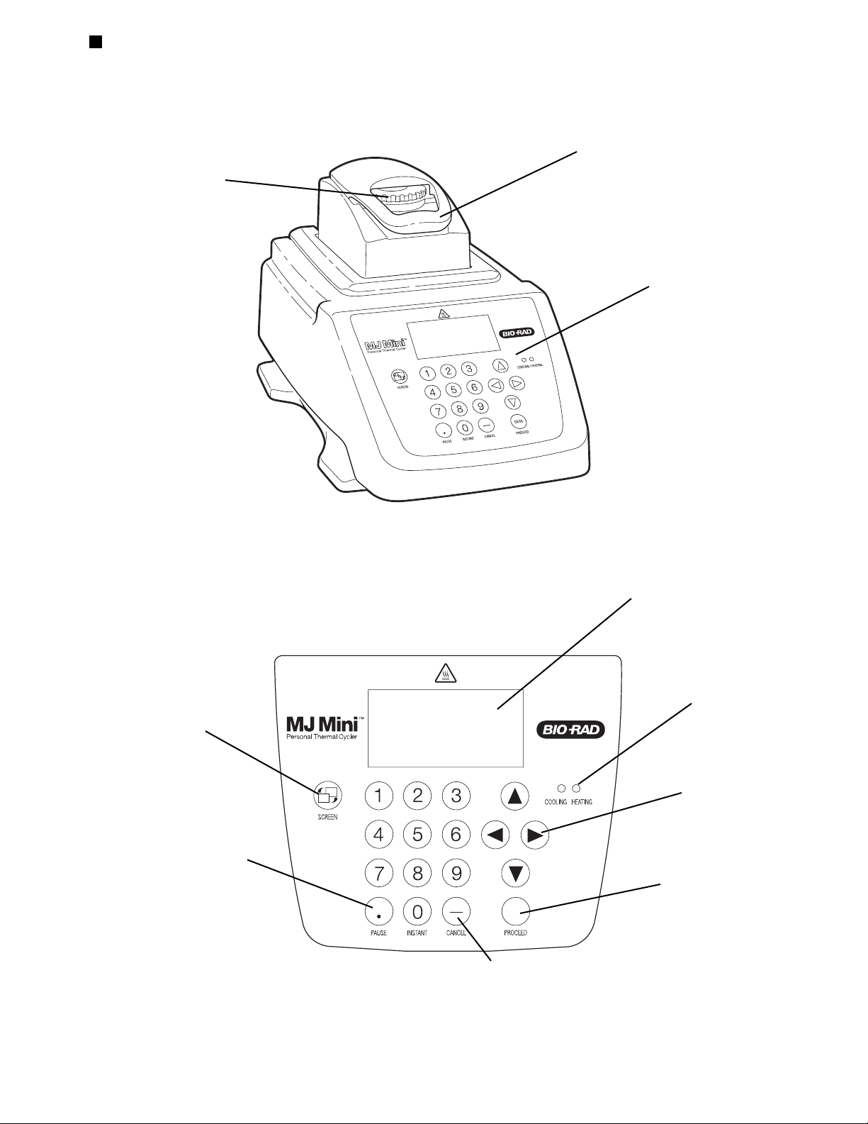
Front View
Figure 2.1
Control Panel
Figure 2.2
Heated lid closed
Thumbwheel
Control panel
Screen hot key
LCD window
Proceed key
Selection keys
Cancel key
Block heating/
cooling lights
Pause key
Layout and Specifications
Tech Support: 1-800-4BIORAD • 1-800-424-6723 • www.bio-rad.com 2-3
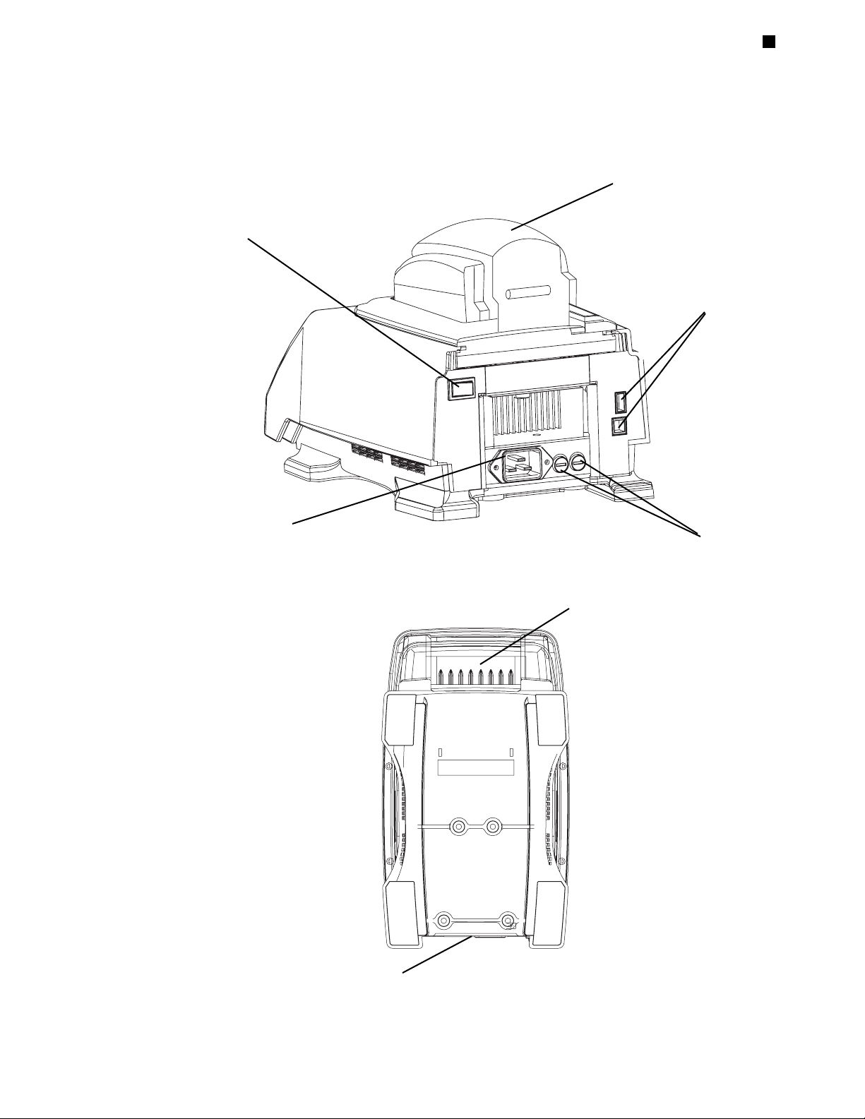
Back View
Figure 2.3
Bottom View
Figure 2.3
Heated lid
Power switch
Fuses
Air intake vents
Air exhaust vents
Front
Back
Jack for power cord
USB ports

MJ Mini Gradient Thermal Cycler Operations Manual
2-4 Tech Support: 1-800-4BIORAD • 1-800-424-6723 • www.bio-rad.com
Specifications
Thermal range: 0–99.9˚C, but no more than 30˚C below ambient
temperature
Thermal accuracy: ±0.2˚C of programmed target @ 90˚C, NIST-traceable
Thermal uniformity: ±0.4˚C well-to-well within 10 sec of arrival at 90˚C
Ramping speed: Average ramp rates are 1.5˚C/sec, with a maximum
rate of 2.5˚C/sec
Sample capacity: 48 x 0.2 ml tubes, 12 x 0.5 ml tubes, or one 48-well
microplate
Line voltage: 100–240 VAC rms (no adjustment needed among
voltages within these ranges)
Frequency: 50–60 Hz single phase
Power: 400 W maximum
Fuses: Two 6.3 A, 250 V, 5 x 20 mm
Displays: 64 x 128 backlit LCD
Ports: Two USB ports allowing retrofitting to MiniOpticon
real-time PCR system, daisy-chaining of MJ Mini
cyclers, and communications or remote control with
an external PC.
Memory: 400 typical programs in 12 folders
Weight: 4.1 kg
Size (W x D x H): 18 x 32 x 20 cm
Gradient Specifications
Temp gradient accuracy:
±
0.2°C of programmed target at end rows, 10 sec after
the timer starts for the gradient step, NIST–traceable
Thermal row uniformity: ±0.4°C , in row, well-to-well, within 10 sec of reaching
target temperature
Calculator accuracy: ±0.4°C of actual row temperature, NIST-traceable
Lowest programmable temperature: 35°C
Highest programmable temperature: 99°C
Temperature differential range: 1–16°C

3-1
Installation
3
Packing Checklist . . . . . . . . . . . . . . . . . . . . . . . . . . . . . . . . . . . . . . . . . . . . . . . . . . .3-2
Setting Up the MJ Mini Instrument . . . . . . . . . . . . . . . . . . . . . . . . . . . . . . . . . . . . .3-2
Environmental Requirements . . . . . . . . . . . . . . . . . . . . . . . . . . . . . . . . . . . . . . . . . .3-2
Power Supply Requirements . . . . . . . . . . . . . . . . . . . . . . . . . . . . . . . . . . . . . . . . . .3-3
Air Supply Requirements . . . . . . . . . . . . . . . . . . . . . . . . . . . . . . . . . . . . . . . . . . . . . .3-3
Ensuring an Adequate Air Supply . . . . . . . . . . . . . . . . . . . . . . . . . . . . . . . . . .3-3
Ensuring That Air Is Cool Enough . . . . . . . . . . . . . . . . . . . . . . . . . . . . . . . . . .3-4

MJ Mini Gradient Thermal Cycler Operations Manual
3-2 Tech Support: 1-800-4BIORAD • 1-800-424-6723 • www.bio-rad.com
Packing Checklist
After unpacking the MJ Mini thermal cycler, check to see that you have received the
following:
• One MJ Mini thermal cycler
• Two spare fuses
• One power cord
• MJ Mini Gradient Thermal Cycler Operations Manual (this document)
If any of these components is missing or damaged, contact Bio-Rad Laboratories to
obtain a replacement. Please save the original packing materials in case you need to
return the instrument for service. See Appendix C for shipping instructions.
Setting Up the MJ Mini Instrument
The MJ Mini cycler requires minimal assembly: plugging in the power cord. Insert the
power cord plug into its jack at the back of the machine (see fig. 2-3 for location of
jack), then plug the cord into an electrical outlet.
Environmental Requirements
Ensure that the area where the thermal cycler is installed meets the following conditions, for reasons of safety and performance:
• Nonexplosive environment
• Normal air pressure (altitude below 2000 m)
• Ambient temperature 5˚–31˚C
• Relative humidity up to 80%
• Unobstructed access to air that is 31˚C or cooler (see below)
• Protection from excessive heat and accidental spills. (Do not place the MJ Mini
near such heat sources as radiators, and protect it from the danger of having water
or other fluids splashed on it, which can cause shorting in its electrical circuits.)

Installation
Tech Support: 1-800-4BIORAD • 1-800-424-6723 • www.bio-rad.com 3-3
Power Supply Requirements
The MJ Mini thermal cycler requires 90–240 V, 50–60 Hz, and a grounded outlet. This
cycler can use current in the specified range without adjustment, so there is no
voltage-setting switch.
Power cords for outlets other than the US 120 V outlet may be purchased from computer stores, since they are also used for most desktop computers and printers and
meet international standard IEC-320. The power cord must be rated to carry at least
10 A at 125 V or 250 V, depending on the voltage available in your nation. The quality
of the power cord can be further ensured by making certain it is inscribed with the
trademark of UL, CSA, TUV, VDE, or another national testing agency.
Note: Do not cut the supplied 120 V power cord and attach a different connector.
Use a one-piece molded connector of the type specified above.
Air Supply Requirements
The MJ Mini thermal cycler requires a constant supply of air. Air is taken in from vents
at the front of the instrument is exhausted from vents at the back (see fig. 2-4). If the
air supply is inadequate or too hot, the machine can overheat, causing performance
problems, software error messages (particularly “HS Overheating” and “Slow Block
Cycling”), and even automatic shutdowns.
Ensuring an Adequate Air Supply
• Do not block the air intake vents.
Position the MJ Mini at least 10 cm from vertical surfaces and other thermal cyclers
(greater distances may be required; see below). Do not put loose papers under or in
front of the machine; they can be sucked into the air vents and cause problems.
• Do not allow dust or debris to collect in the air intake vents.
The air vents are particularly liable to collect dust and debris, sometimes completely
clogging up. Check for dust and debris every few months, and clean the intake vents
as needed. Remove light collections of dust with a soft-bristle brush or damp cloth.
Severe collections of dust and debris should be vacuumed out. Turn the machine off
prior to cleaning or vacuuming air vents.

MJ Mini Gradient Thermal Cycler Operations Manual
3-4 Tech Support: 1-800-4BIORAD • 1-800-424-6723 • www.bio-rad.com
Ensuring That Air Is Cool Enough
• Do not position two or more thermal cyclers so that the hot exhaust air of one
blows directly into the air intake vents of another.
• Make sure the MJ Mini receives air that is 31˚C or cooler by measuring the temperature of air entering the machine through its air intake vents. Air intake vents are
located at the front of the machine (see fig. 2-4).
Place the thermal cycler where you plan to use it, and turn it on. Try to reproduce
what will be typical operating conditions for the machine in that location, particularly
any heat-producing factors (e.g., nearby equipment running, window blinds open,
lights on). Run a typical protocol (e.g., BASIC) for 30 minutes to warm up the cycler,
then measure the air temperature at the air intake vents. If more than one machine
is involved, measure the air temperature for each.
If the air intake temperature of any machine is warmer than 31˚C, use table 3-1 to
troubleshoot the problem. Some experimentation may be required to determine the
best solution when more than one cause is involved. After taking steps to solve the
problem, verify that the temperature of the air entering the air intake vents has been
lowered, using the procedure outlined above.
Cause Possible Remedies
Air circulation is poor. Provide more space around machine or adjust room ventilation.
Ambient air temperature Adjust air conditioning to lower ambient air temperature.
is high.
Machine is in warm part Move machine away from, or protect machine from, such heat
of room. sources as radiators, heaters, other equipment, or bright sunlight.
Machines are crowded. Arrange machines so that warm exhaust air does not enter intake
vents.

4-1
Operation
4
Turning the MJ Mini Cycler On . . . . . . . . . . . . . . . . . . . . . . . . . . . . . . . . . . . . . . . . .4-2
Understanding the Main Menu . . . . . . . . . . . . . . . . . . . . . . . . . . . . . . . . . . . . . . . . .4-2
Using the Control Panel . . . . . . . . . . . . . . . . . . . . . . . . . . . . . . . . . . . . . . . . . . . . . .4-3
Operation Keys . . . . . . . . . . . . . . . . . . . . . . . . . . . . . . . . . . . . . . . . . . . . . . . .4-3
Status Indicator Lights . . . . . . . . . . . . . . . . . . . . . . . . . . . . . . . . . . . . . . . . . . .4-3
Using the Data Ports . . . . . . . . . . . . . . . . . . . . . . . . . . . . . . . . . . . . . . . . . . . . . . . . .4-4
Opening and Closing a Sample Block . . . . . . . . . . . . . . . . . . . . . . . . . . . . . . . . . .4-4
Selecting the Correct Sample Vessel . . . . . . . . . . . . . . . . . . . . . . . . . . . . . . . . . . . .4-4
0.5 ml Tubes . . . . . . . . . . . . . . . . . . . . . . . . . . . . . . . . . . . . . . . . . . . . . . . . . . .4-4
Thin-Walled Vs. Thick-Walled Tubes . . . . . . . . . . . . . . . . . . . . . . . . . .4-5
0.2 ml Tubes . . . . . . . . . . . . . . . . . . . . . . . . . . . . . . . . . . . . . . . . . . . . . . . . . . .4-5
Microplates . . . . . . . . . . . . . . . . . . . . . . . . . . . . . . . . . . . . . . . . . . . . . . . . . . . .4-5
Sealing Sample Vessels . . . . . . . . . . . . . . . . . . . . . . . . . . . . . . . . . . . . . . . . . . . . . .4-5
Sealing with Oil or Wax . . . . . . . . . . . . . . . . . . . . . . . . . . . . . . . . . . . . . . . . . .4-5
Sealing with the Hot Bonnet Lid . . . . . . . . . . . . . . . . . . . . . . . . . . . . . . . . . . .4-6
Adjusting the Hot Bonnet Lid’s Pressure . . . . . . . . . . . . . . . . . . . . . . .4-7
Loading Sample Vessels into the Block . . . . . . . . . . . . . . . . . . . . . . . . . . . . . . . . .4-8
Using Oil to Thermally Couple Sample Vessels to the Block . . . . . . . . . . . . .4-8
Appendix 4-A Tube, Microplate, and Sealing System Selection Chart . . . . . . . .4-9
Appendix 4-B Safety Warning Regarding Use of
35
S Nucleotides . . . . . . . . . . .4-10
The Problem . . . . . . . . . . . . . . . . . . . . . . . . . . . . . . . . . . . . . . . . . . . . . . . . . .4-10
96-well Polycarbonate Microplates . . . . . . . . . . . . . . . . . . . . . . . . . .4-10
0.2 ml Polypropylene Tubes and Polypropylene Microplates . . . . . .4-10
0.5 ml Polypropylene Tubes . . . . . . . . . . . . . . . . . . . . . . . . . . . . . . . .4-10
The Solution . . . . . . . . . . . . . . . . . . . . . . . . . . . . . . . . . . . . . . . . . . . . . . . . . .4-11

MJ Mini Gradient Thermal Cycler Operations Manual
4-2 Tech Support: 1-800-4BIORAD • 1-800-424-6723 • www.bio-rad.com
Turning the MJ Mini Cycler On
Move the power switch to “o” (the “On” position). The fan will turn on, and the
Cooling/Heating lights on the keyboard will flash. The MJ Mini will enter a self-test
of the heat pumps.
Note: If the sample block or the heat sink is not at ambient temperature (typically
because the sample block was recently in use), the machine will skip the self-test.
If the self-test does not detect any problems, the Main Menu is displayed.
Alternatively, depressing the «Screen» button will bring you to the main screen.
The MJ Mini is now ready to execute programs.
Understanding the Main Menu
The Main Menu is the common access point to all programming and machine configuration screens:
• RUN: Executes a program.
• NEW: Allows new programs to be entered.
• EDIT: Allows modification of stored programs.
• VIEW: Accesses utilities that display a program’s steps.
• FILES: Accesses file management utilities.
• TOOLS: Accesses machine configuration screens.
RUN VIEW
NEW FILES
EDIT TOOLS
Block is idle

Operation
Tech Support: 1-800-4BIORAD • 1-800-424-6723 • www.bio-rad.com 4-3
Using the Control Panel
The control panel (see fig. 2-2) includes operation keys, status indicator lights for
heating and cooling, an LCD window for displaying programming and machine
status text, and a numeric keypad for entering values into programs.
Operation Keys
• Select keys (left, right, up, down arrows): Move the cursor one space or option
in the LCD window.
• Proceed/Enter: Accepts a selected menu or screen option; during a protocol run,
advances the program to its next step.
• Cancel: Terminates a running protocol; during program creation or editing, can-
cels the last entry.
• Pause: Pauses a protocol during execution.
• Instant: Initiates a program that sets up the MJ Mini as a simple incubator.
• Screen: Switches between protocol status screens, the Main Menu and a time
remaining display in the LCD window during a protocol run. In addition, this button
toggles between the Main Menu and the “About” screen for the instrument, and
allows the users to alternately view the text and graphical programming screens.
Status Indicator Lights
• Block Status lights: Indicate whether the sample block is heating (red light is illu-
minated) or cooling (blue light is illuminated).

MJ Mini Gradient Thermal Cycler Operations Manual
4-4 Tech Support: 1-800-4BIORAD • 1-800-424-6723 • www.bio-rad.com
Using the Data Ports
The MJ Mini thermal cycler has two USB ports located at the rear of the machine, a
USB A (upper) port and a USB B (lower) port. These ports allow the MJ Mini thermal
cycler to be connected in series and operated centrally from a single PC. The USB A
port is used to connect the first cycler to the PC and the USB B port connects to the
USB A port or the next MJ Mini cycler in the chain. Up to four instruments may be
serially connected in this manner. Alternatively, up to four MJ Mini thermal cyclers
may be connected to a PC via a USB hub.
Protocols are programmed and run from the PC using Opticon Monitor
™
software
(which is available for download from our website). Note that a separate instance of
the software should be opened for each networked MJ Mini cycler.
Opening and Closing a Sample Block
Grip the front handle of the Hot Bonnet®heated lid and pull upward firmly. The top
lever will pop open to reveal the entire thumbwheel. Continue pulling upward to open
the Hot Bonnet. The Hot Bonnet will tip backward, revealing the entire block.
Caution: Do not pull on the thumbwheel to open the unit. This can damage the Hot
Bonnet’s closing mechanism.
To close the sample block, press down on the top lever. The lever will close down
over the thumbwheel as the Hot Bonnet closes down over the sample block. A click
signifies that the Hot Bonnet’s latch has engaged.
Selecting the Correct Sample Vessel
The MJ Mini accepts both 0.2 ml and 0.5 ml tubes as well as 48-well microplates.
Keep in mind that differences in tube and plate composition and wall thickness
among the many brands available can affect reaction performance. Protocols may
require some adjustment to ensure optimum performance when using a new vessel
type. Bio-Rad offers a full range of tubes and microplates manufactured to the specifications of sample block of MJ line cyclers. See chapter appendix 4-A for a
complete list.
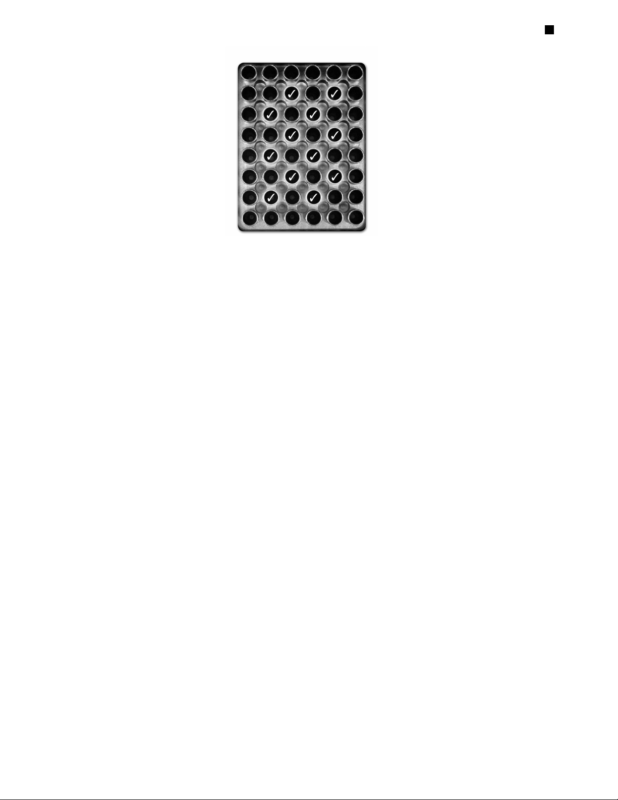
0.5 ml Tubes
It is possible to load up to twelve 0.5 ml tubes in the MJ Mini cycler. Since the width
of the 0.5 ml tubes does not allow them to be accommodated in adjacent wells, the
tubes should be placed in a staggered fashion (i.e., in every other well in the block).
The tubes should NOT be placed in the spaces between wells. Furthermore,
placement of tubes in the peripheral wells along the edge of the cycler block should
be avoided, as this may result in compromised amplification due to condensate formation. For correct placement of 0.5 ml tubes, see Figure 4-1.
Tech Support: 1-800-4BIORAD • 1-800-424-6723 • www.bio-rad.com 4-5
When using 0.5 ml tubes, thin-walled tubes are recommended; these are specifically
designed for thermal cycling and the higher-quality brands provide a good and consistent fit. If thick-walled 0.5 ml tubes are used, ensure that they fit the wells snugly.
(Since these tubes were originally designed for centrifuges, some brands may not fit
tightly in thermal cycler wells.) Both thin and thick-walled 0.5 ml tubes are available
from Bio-Rad and are designed for precise block fit.
Thin-Walled Vs. Thick-Walled Tubes
The thickness of sample tubes directly affects the speed of sample heating and thus
the amount of time required for incubations. Thick-walled tubes delay sample
heating, since heat transfers more slowly through the tubes’ walls. For the earliest
types of thermal cyclers this delay mattered little. These machines’ ramping rates
were so slow (below 1°C/sec) that there was plenty of time for heat to transfer
through the tube wall to the sample, during a given incubation.
Modern thermal cyclers have much faster ramping rates, so the faster heat transfer
provided by thin-walled tubes allows protocols to be significantly shortened.
Essentially, up to 30 seconds can be saved per cycle by using thin-walled tubes, for
an overall savings of 15 minutes in a 30-cycle run.
0.2 ml Tubes
All types of thin-walled 0.2 ml tubes may be used. Bio-Rad sells high-quality 0.2 ml
tubes in a number of styles, including individual tubes and strips.
Microplates
A variety of polypropylene 48-well microplates can be used in the MJ Mini cycler as
long as they fit the wells snugly. In addition, the Multiplate line of 96-well plates and
Microseal
®
film seals can be cut down to fit in the sample block of this instrument.
Polypropylene microplates and compatible Microseal film or strip caps for sealing
Figure 4-1. Wells () in which 0.5 ml tubes should be placed
Operation

MJ Mini Gradient Thermal Cycler Operations Manual
4-6 Tech Support: 1-800-4BIORAD • 1-800-424-6723 • www.bio-rad.com
are available from Bio-Rad Laboratories.
Sealing Sample Vessels
To avoid changing the concentration of reactants, steps must be taken to prevent the
evaporation of water from reaction mixtures during thermal cycling. Only a layer of
oil or wax will completely prevent evaporation from the surface of the reaction fluid.
However, an adequate degree of protection can be achieved by sealing vessels with
caps, film, or adhesive seals then cycling the samples using the heated lid to prevent
condensation.
Sealing with Oil or Wax
Mineral oil, silicone oil, paraffin wax, or Chill-out™ liquid wax may be used to seal
samples. Use only a small amount of oil or wax; 1-3 drops (15–50 µl) are usually sufficient. (Include this volume in the total volume when setting up a calculated-control
protocol; see “Choosing a Temperature Control Mode” in chapter 5.) Use the same
amount of oil or wax in all sample vessels to ensure a uniform thermal profile.
Most paraffin waxes solidify at room temperature. The wax can then be pierced with
a micropipette tip and the samples drawn off from below the wax. Silicone oil and
mineral oil can be poured off or aspirated from tubes if the samples are first frozen
(–15° to –20°C). The samples are usually pure enough for analysis without an extraction.
Chill-out liquid wax (available from Bio-Rad Laboratories) is an easy-to-use alternative to oil. This purified paraffinic oil solidifies at 10°C and is liquid at room
temperature. By programming a holdstep at low temperature, the wax can be solidified at the end of a run. A pipette tip can then be used to pierce the wax in the tubes
and remove the samples. The wax is available in a clear, optical-assay grade or dyed
red to assist in monitoring its use. The red dye has no adverse effects on fluorescent
gel analysis of reaction products.
Sealing with the Hot Bonnet Lid
The Hot Bonnet’s heated inner lid maintains the air in the upper part of sample vessels at a higher temperature than the reaction mixture. This prevents condensation
of evaporated water vapor onto the vessel walls and lid, so that solution concentrations are unchanged by thermal cycling. The Hot Bonnet lid also exerts pressure on
the tops of vessels loaded into the block, helping to maintain a vapor-tight seal and
to firmly seat tubes or the plate in the block.
Caps, film, adhesive seals, or mats must be used along with the Hot Bonnet lid to
prevent evaporative losses.
Note: When tubes are cooled to below-ambient temperatures, a ring of condensa-

Operation
Tech Support: 1-800-4BIORAD • 1-800-424-6723 • www.bio-rad.com 4-7
tion may form in tubes above the liquid level but below the top of the sample block.
This is not a cause for concern since it occurs only at the final cool-down step, when
thermal cycling is complete.
Microseal® 'A' film offers a quick alternative to sealing microplates or arrays of tube
strips. This film is specially designed to seal tightly during cycling, yet release
smoothly to minimize the risk of aerosol formation and cross-contamination of samples. Microseal 'A' film, designed to cover a 96-well plate, is easily cut for use with
fewer than 96 samples.
Microseal 'B' adhesive seals feature an aggressive adhesive, effective from –20°C to
110°C, which allows secure sample storage or transport before and after cycling.
The clear polyester backing allows easy inspection of sample wells. Microseal 'B'
clear, adhesive seals are ideal for thermal cycling in all polypropylene and polystyrene microplates. Microseal 'B' adhesive seals can be easily cut for use with fewer
than 96 samples.
Microseal 'F' aluminized foil acts as a barrier against evaporation from –20˚C to
105˚C. In addition to cold storage applications, it can also be used for thermal
cycling sample volumes ≥25 µl. The foil is thin enough to pierce with a pipet tip for
recovery of sample from individual wells. Microseal 'F' foil is easily cut for use with
fewer than 96 samples.
Adjusting the Hot Bonnet Lid’s Pressure
The pressure exerted by the Hot Bonnet lid must be manually adjusted to fit the
sample vessels being used. Once set, the Hot Bonnet lid can be opened and closed
repeatedly without readjustment as long as neither the tube or microplate type nor
the sealing method is changed. Any change in vessel type or sealing method
requires readjustment of the Hot Bonnet lid.
Follow these steps to adjust the pressure exerted by the inner lid:
1. Make sure the block’s wells are clean. Even tiny amounts of extraneous material
can decrease thermal conductance and interfere with the proper seating of a
microplate or tubes.
2. Open the Hot Bonnet lid. Turn the thumbwheel all the way counterclockwise to
completely raise the inner lid.
3. Load either a microplate or at least eight individual tubes into the sample block.
The inner lid pivots around a central point, so it is important to distribute individual
tubes evenly: load at least four tubes in the center of the block and at least one tube
in each of the four corners of the block. If using a sealing film or mat, apply it to the
loaded microplate according to the manufacturer’s directions.

MJ Mini Gradient Thermal Cycler Operations Manual
4-8 Tech Support: 1-800-4BIORAD • 1-800-424-6723 • www.bio-rad.com
4. Close the Hot Bonnet lid by pressing down on the top lever. Turn the thumbwheel
clockwise to lower the inner lid onto the loaded microplate/tubes. The thumbwheel
turns easily at first since the inner lid has not yet come into contact with anything.
Stop turning the thumbwheel when you feel increased resistance, which indicates
that the inner lid has touched the microplate/tubes.
5. For microplate sealing films or mats that require additional pressure, turn the
thumbwheel clockwise an extra half turn past the point of initial contact to set an
appropriate lid pressure.
Caution: Do not turn the thumbwheel more than three-quarters of a turn. This can
make it hard or impossible to close the lid and puts excessive strain on the latch
holding the lid closed.
An extra half to three-quarters of a turn ensures the correct pressure for most types
of reaction vessels. Some empirical testing may be required to determine the
optimum pressure required for certain vessels. Once this pressure has been determined, the thumbwheel position may be marked with a colored marking pen or piece
of tape.
Note: As an aid in gauging how much the thumbwheel has been turned, mark it at
the quarter turn positions, or every sixth “bump” on the thumbwheel (there are 24
total “bumps”).
Loading Sample Vessels into the Block
When using a small number of tubes, load at least one empty tube in each corner of
the block to ensure that the Hot Bonnet lid exerts even pressure on the sample tubes
(see “Adjusting the Hot Bonnet Lid’s Pressure,” above).
To ensure uniform heating and cooling of samples, sample vessels must be in complete contact with the block. Adequate contact is ensured by always doing the
following:
• Ensure that the block is clean before loading samples (see chapter 9 for cleaning
instructions).
• Firmly press individual tubes or the microplate into the block wells.
Using Oil to Thermally Couple Sample Vessels to the Block
With two exceptions (see below), Bio-Rad does not recommend using oil to thermally couple sample vessels to the block, for the following reasons:
• Calculated-control protocols do not run accurately when oil is used.
• Oil traps dirt, which interferes with thermal contact between vessels and the
block.

Operation
Tech Support: 1-800-4BIORAD • 1-800-424-6723 • www.bio-rad.com 4-9
• Calculated-control protocols do not run accurately when oil is used.
• Oil traps dirt, which interferes with thermal contact between vessels and the block.
Caution: If you use oil in the block, use only mineral oil. Never use silicone oil. It can
damage the sample block.
One exception to this recommendation involves the use of volatile radioactive 35S
nucleotides. A small amount of oil in the block can help prevent escape of these compounds. See appendix 4-B of this chapter for important information regarding safe use
of these compounds in polypropylene tubes and polypropylene and polycarbonate
microplates. A second exception involves the use of thick-wall 0.5 ml tubes. Certain
brands of these tubes fit poorly in the block, in which case, oil may somewhat improve
thermal contact. Whenever possible, use high-quality thin-wall tubes intended for
thermal cycling (see appendix 4-A of this chapter for a tube and plate selection chart).
Appendix 4-A Tube, Microplate, and Sealing System
Selection Chart
The following sample vessels and sealing options are recommended for use with the MJ
Mini thermal cycler. These items are available from Bio-Rad Laboratories.
Key
Reaction vessel fits block/sealing option fits reaction vessel without modification.
Reaction vessel/sealing option can be cut to fit.
Thermal
Cycler
Sealing Options for Oil-Free CyclingReaction Vessels
MJ Mini
Bio-Rad
catalog #
Microseal
‘A’ film
MSA-5001
Microseal
‘B’ seal
MSB-1001
Microseal
‘F’ foil
MSF-1001
Strip caps
TCS-series
Chill-out
wax
CHO-series
Description
MLP-series
MLL-series
Multiplate unskirted
96-well microplates
MLP-series
Multiplate unskirted
48-well microplates
MLP-2401
Multiplate unskirted
24-well microplates
TBS-series
TLS-series
0.2 ml strip tubes
8/strip & 12/strip
TFI-0201
TBI-series
0.2 ml individual tubes
TBI-series
0.5 ml individual tubes,
w/ caps

MJ Mini Personal Thermal Cycler Operations Manual
4-10 Tech Support: (888) 652-9253 • Sales: (888) 735-8437 • tech@mjr.com
Appendix 4-B Safety Warning Regarding Use of 35S
Nucleotides
Some researchers have experienced a problem with radioactive contamination when
using 35S in thermal cyclers. This problem has occurred with all types of reaction
vessels.
The Problem
When 35S nucleotides are thermally cycled, a volatile chemical breakdown product
forms, probably SO
2
. This product can escape the vessel and contaminate the
sample block of a thermal cycler, and possibly, the air in the laboratory.
Contamination has been reported with microassay plates, 0.2 ml tubes, and 0.5 ml
tubes.
0.2 ml Polypropylene Tubes and Polypropylene Microplates
These tubes are manufactured with very thin walls to enhance thermal transfer. The
thin walls are somewhat fragile and can “craze” or develop small cracks when subject to mechanical stress. Undamaged thin polypropylene tubes may also be
somewhat permeable to the
35
S breakdown product. Either way, there have been
reports of
35
S passing through the walls of 0.2 ml tubes of several different brands
during thermal cycling. No data are yet available on radioactive contamination with
polypropylene microplates.
0.5 ml Polypropylene Tubes
Contamination problems are rarer with this type of tube, but instances have been
reported.

Operation
Tech Support: 1-800-4BIORAD • 1-800-424-6723 • www.bio-rad.com 4-11
The Solution
1. Substitute the low-energy beta emitter 33P in cycle sequencing. 33P nucleotides
are not subject to the same kind of chemical breakdown as 35S nucleotides, and
they have not been associated with volatile breakdown products.
2. If
35
S must be used, three things will help control contamination: an oil overlay
inside the tubes, mineral oil in the thermal cycler outside the tubes, and use of thickwalled 0.5 ml tubes. Always run
35
S thermal cycling reactions in a fume hood, and
be aware that vessels may be contaminated on the outside after thermal cycling.
Please be certain that you are using the appropriate detection methods and cleaning
procedures for this isotope. Consult your radiation safety officer for his or her recommendations.
If mild cleaning agents do not remove radioactivity, harsher cleaners may be used
occasionally and carefully. Users have suggested the detergent PCC-54 (Pierce
Chemical Co., Rockford, Illinois; Pierce Eurochemie B.V., Holland), Micro Cleaning
Solution (Cole-Parmer, Niles, Illinois), and Dow Bathroom Cleaner (available in supermarkets).
Caution: Harsh cleaning agents (such as those above) are corrosive and must be
thoroughly rinsed away within a few minutes of application. They can eat away the
surface finish of the blocks.


5-1
Running Protocols
5
Running a Protocol . . . . . . . . . . . . . . . . . . . . . . . . . . . . . . . . . . . . . . . . . . . . . . . . . .5-2
Choosing a Stored Protocol to Run . . . . . . . . . . . . . . . . . . . . . . . . . . . . . . . . .5-2
Selecting Temperature Control Mode vs. Block Control Mode . . . . . . . . . . . .5-3
Reading the Runtime Screen . . . . . . . . . . . . . . . . . . . . . . . . . . . . . . . . . . . . . . . . . .5-4
Reading the Temperature Display Screen . . . . . . . . . . . . . . . . . . . . . . . . . . . . . . . .5-4
Time Remaining Screen . . . . . . . . . . . . . . . . . . . . . . . . . . . . . . . . . . . . . . . . . .5-5
Reading the Protocol Completion Screen . . . . . . . . . . . . . . . . . . . . . . . . . . . . . . .5-6
Manually Stepping Through a Protocol . . . . . . . . . . . . . . . . . . . . . . . . . . . . . . . . . .5-6
Pausing a Running Protocol . . . . . . . . . . . . . . . . . . . . . . . . . . . . . . . . . . . . . . . . . . .5-6
Stopping a Running Protocol . . . . . . . . . . . . . . . . . . . . . . . . . . . . . . . . . . . . . . . . . .5-7
Resuming a Protocol After a Power Outage . . . . . . . . . . . . . . . . . . . . . . . . . . . . . .5-8
Using the Instant Incubation Feature . . . . . . . . . . . . . . . . . . . . . . . . . . . . . . . . . . .5-8

MJ Mini Gradient Thermal Cycler Operations Manual
5-2 Tech Support: 1-800-4BIORAD • 1-800-424-6723 • www.bio-rad.com
Running a Protocol
Running a protocol on the MJ Mini thermal cycler involves two steps:
1. Choosing a stored protocol to run
2. Setting up the temperature control method
Either a custom-designed protocol or one of the factory-installed resident protocols
may be run. See appendix E for descriptions of the resident protocols, which may be
edited to fit your needs (see chapter 7 for instructions on editing stored programs).
All the factory-installed protocols are stored in a single folder, called the <MAIN>
folder, at the time of shipping.
Choosing a Stored Protocol to Run
With the Main Menu displayed, select Run, then press «Proceed». One of two types
of screen will be displayed, depending on whether custom protocols have been
stored in the <MAIN> folder or in custom folders:
• If all protocols have been stored in the <MAIN> folder:
A screen listing the protocols will be displayed. Custom protocols are listed first, followed by the factory-installed programs:
Use the Select keys to scroll through the listed protocols. Scroll past the last- or firstlisted protocol to see the next screen down or up. Select the desired protocol, then
press «Proceed».
• If custom protocols have been stored in one or more custom folders:
A list of folders will appear on the left of the screen and a list of programs residing in
these folders will appear on the right. In the example below, since the MAIN folder is
highlighted, the list of programs that reside in the MAIN folder appears on the right.
Run: PROGRAMS
<MAIN> iPRF1kb
iPRF8kb
iPRF15kb
LONG-2
LONG-3
Run: PROGRAMS
<<MMAAIINN>> iPRF1kb
<FOLDER1> iPRF8kb
<FOLDER2> iPRF15kb
LONG-2
LONG-3

Running Protocols
Tech Support: 1-800-4BIORAD • 1-800-424-6723 • www.bio-rad.com 5-3
Select the folder that contains the protocol you wish to run, then press the right
«Select» key to toggle over to the list of protocols located in that folder. Use the
Select keys to scroll through the listed protocols and select the desired protocol,
then press «Proceed».
In either instance, after you press «Proceed», a screen similar to the one below will
be displayed:
The top line of the screen will identify the selected protocol (iPRF1kb in the example).
The other lines on the screen will request information needed to set up the temperature control method (explained below). Enter the reaction volume and press
«Proceed». The cursor moves over to the «Run» option. However, before you run the
protocol, you may select to VIEW the protocol steps, by selecting «View» and
pressing «Proceed».
The steps are listed along with the default heated lid temperature and selected reaction volume. In this case, you need to use the «Select» keys to scroll downward to
view all protocol steps.
By selecting «Proceed» again, you are brought back to the previous screen, from
which you can highlight and select «Run» to commence the cycling program.
Tip: The MJ Mini thermal cycler comes pre-loaded with a series of template protocols for a variety of common applications (See Appendix C for a full list of included
protocols). You may chose to run these programs as they are, or to adjust certain
parameters in order to optimize your reactions.
Run:
iPRF1kb?
Sample Vol: 20µl
RUN VIEW
View: Lid:100˚C
iPRF1kb Vol: 20µl
1= 95.0˚, 2:00
2= 92.0˚, 0:01
3= 70.0˚, 0:10

MJ Mini Gradient Thermal Cycler Operations Manual
5-4 Tech Support: 1-800-4BIORAD • 1-800-424-6723 • www.bio-rad.com
Selecting Temperature Control Mode vs. Block Control Mode
With the MJ Mini thermal cycler, the default setting for running a protocol is
Temperature Control Method. This temperature control method compensates for the
fact that the sample’s temperature lags behind the block temperature. When creating
a new protocol, you will be asked to enter a sample volume. The cycler will automatically take this volume into account when running the protocol and by employing
small temperature overshoots, the cycler rapidly brings the sample to its target temperature. Every time you select a protocol to run, you will be asked to enter a sample
volume.
By entering zero in the Sample Vol field, the cycler will enter Block Control Mode, this
mode does not employ the small temperature overshoots. As a result, it will take
slightly longer for the sample to reach its target temperature and the protocol will
generally take a little longer to run.
Reading the Runtime Screen
When a protocol is running, a runtime screen will be displayed:
The screen lists: the protocol name (iPRF1kb in the example above), protocol step
that is running (Step 1), and either the block temperature for block-control protocols
or the calculated sample temperature for calculated-control protocols. When the
step’s target temperature is reached, a timer starts in the “Temp” line (min:sec).
By pressing the Left arrow button, you can view the lid temperature. This screen
shows only as long as the left «Select» key is pressed. The runtime screen returns
when you stop pressing the key.
By pressing the Right arrow button, you can view the total time that the protocol has
been running, the total time remaining in the protocol, and the cycler number that the
protocol is currently running. This screen is displayed only as long as the key is
pressed. The runtime screen returns when you stop pressing the key.
Running:
iPRF1kb
Step 1: 95.0˚ 2:00
Step 2: 92.0˚ 0:01
Step 3: 70.0˚ 0:10

Running Protocols
Tech Support: 1-800-4BIORAD • 1-800-424-6723 • www.bio-rad.com 5-5
Reading the Temperature Display Screen
By pressing the «Screen» button, you can toggle between different screens during a
protocol. Pressing the button once will bring you to the temperature display screen:
This screen lists a shorthand version of the protocol. On the left, the list of the temperature steps appears. In this case, the denaturation temperature (90.0) is followed
by the annealing temperature (64.0) as well as an extension time of 72.0. This temperature pattern is repeated 29 times (as indicated by the GOTO step in the protocol,
as well as the 29x shown at the bottom of the screen). This cycling is followed by a
final hold step of 10.0. On the right, a diagrammatic representation of the protocol is
presented. In the example above, the cycler is currently holding the samples at
64.0˚C. On the left, this step is highlighted, and on the diagrammatic representation
this step is blinking. A counter on the top line of this screen marks the amount of time
that has passed on this step (min:sec).
Time Remaining Screen
Press the «Screen» button once more, to see the time remaining in the protocol:
The time is noted in hours:min:sec. In this case, there are 25 minutes and 55 seconds remaining until the program is complete. This screen is particularly useful in lab
settings where multiple cyclers are being run.
00:25:55
Time Remaining
90.0 0:09
6644..00
72.0
GOTO
10.0
29x

MJ Mini Gradient Thermal Cycler Operations Manual
5-6 Tech Support: 1-800-4BIORAD • 1-800-424-6723 • www.bio-rad.com
From the Time Remaining Screen, pressing the «Screen» button returns the user to
the Main Menu. This is the same screen that we have encountered previously, except
that the bottom line indicates that the thermal cycler is engaged in running a protocol.
Reading the Protocol Completion Screen
When the protocol finishes, a long beep sounds and the Main Menu appears. From
this Main Menu, you may select the «Screen» button to review the parameters of the
protocol that just finished running.
Certain error messages may also be displayed in this screen (see chapter 11). Press
«Proceed» to return to the Main Menu.
Manually Stepping Through a Protocol
During a protocol run, pressing «Proceed» allows you to advance the protocol to the
next programmed step, even if the machine is currently ramping the block’s temperature (see chapter 6 for information on ramping). A confirmation screen will be
displayed:
Select Yes, then press «Proceed». The protocol will advance to its next step.
LAST RUN: iPRF1kb
HOTLID: 99,30
VOLUME: 20
ELAPSED: 8:47
ERRORS: None
SOFTWARE: v.1.1A
Running:
iPRF1kb
Step 1: 90.0˚ 0:25
Temp: 90.0˚ 0:10
Cycle 2 of 39
Goto next step? Yes NNoo
RUN VIEW
NEW FILES
EDIT TOOLS
Running: iPRF1kb

Running Protocols
Tech Support: 1-800-4BIORAD • 1-800-424-6723 • www.bio-rad.com 5-7
Pausing a Running Protocol
Press «Pause» to temporarily stop a running program. The clock will be replaced with
the word “Pause” on the runtime protocol screen:
The samples are held at the displayed temperature until either the «Pause» or the
«Proceed» key is pressed, which causes the protocol run to resume.
A protocol cannot be paused before the target temperature for a given step has been
reached. If «Pause» is pressed before this point, the block continues heating or
cooling until the target is reached, and then the protocol is paused.
Stopping a Running Protocol
Press «Cancel» to stop a running protocol. A cancellation confirmation screen will be
displayed:
Select Yes, then press «Proceed» to cancel the protocol. The total run time for the
protocol will be displayed:
Press «Proceed» to return to the Main Menu.
Running:
iPRF1kb
Step 1: 90.0˚ 0:25
Temp: 90.0˚ 0:10
Cycle 2 of 39
Cancel iPRF1kb Yes NNoo
PROGRAM CANCELLED
Total Time: 3:21
Running:
iPRF1kb
Step 1: 90.0˚ 0:25
Temp: 90.0˚ PAUSE
Cycle 2 of 39

MJ Mini Gradient Thermal Cycler Operations Manual
5-8 Tech Support: 1-800-4BIORAD • 1-800-424-6723 • www.bio-rad.com
Note: If the cycler is currently ramping to a temperature, the thermal cycler will continue ramping until it reaches its target temperature at which point, you will be able
to cancel the program.
Note: Turning off the machine does not stop a running protocol. The MJ Mini will
assume the protocol was stopped by a power outage and will resume running the
protocol when the machine is turned back on (see below).
Resuming a Protocol After a Power Outage
If a power failure occurs when a protocol is running, the MJ Mini will hold the protocol in memory for a minimum of 24 hours to a maximum of 7 days, depending on
environmental conditions.
When power is restored, the protocol will begin running from the point at which it
was interrupted, and a notice about the power interruption will be displayed. The
notice will identify the step and the cycle at which the power failure occurred, as well
as the block’s temperature at the time power was restored:
Press «Proceed» to remove this screen. The protocol’s diagrammatic screen will
immediately be displayed.
Using the Instant Incubation Feature
The MJ Mini may be converted to a constant-temperature incubator by pressing
«Instant». A screen allowing use of the heated lid will be displayed:
Running:
A/C POWER FAILED
CYCLE 1 STEP 1
RECOVERED AT 46.8
PRESS PROCEED
TO CONTINUE
INCUBATE:
Use heated lid?
Yes NNOO

Running Protocols
Tech Support: 1-800-4BIORAD • 1-800-424-6723 • www.bio-rad.com 5-9
Use the «Select» keys to enable or disable the heated lid, then press «Proceed». A
screen allowing entry of the incubation temperature will be displayed.
Use the keypad to enter any incubation temperature from 0˚C to 99.9˚C, then press
«Proceed». The thermal cycler will incubate the sample at the specified temperature
until «Cancel» is pressed.
When the sample block reaches the incubation temperature (and when the heated
lid achieves the set temperature), a timer begins running on the screen. To stop and
start the timer, press «Pause».
Tip: The Pause feature is useful if you need to temporarily remove samples that must
be incubated for a precise period of time. Pausing the timer while samples are not in
the block allows you to track the exact duration of their incubation.
Incubating to:
75.0˚C
STEP 1:75.0˚ FOREVER
TEMP: 75.0˚
Preheating Lid
Incubate to 7755..00˚


6-1
Creating Programs
6
The Elements of a Program . . . . . . . . . . . . . . . . . . . . . . . . . . . . . . . . . . . . . . . . . . .6-3
Designing a New Program . . . . . . . . . . . . . . . . . . . . . . . . . . . . . . . . . . . . . . . . . . . .6-4
Translating a Protocol into a Program . . . . . . . . . . . . . . . . . . . . . . . . . . . . . . .6-4
Using the GoTo Step to Write Short Programs . . . . . . . . . . . . . . . . . . . . . . . .6-4
Choosing a Temperature Control Method . . . . . . . . . . . . . . . . . . . . . . . . . . . .6-4
Calculated Control . . . . . . . . . . . . . . . . . . . . . . . . . . . . . . . . . . . . . . . .6-5
Block Control . . . . . . . . . . . . . . . . . . . . . . . . . . . . . . . . . . . . . . . . . . . .6-5
Modifying Block-Control Programs for Calculated Control . . . . . . . . .6-5
Modifying a Program Designed for a Different Machine . . . . . . . . . . . . . . . . .6-5
Entering a New Program . . . . . . . . . . . . . . . . . . . . . . . . . . . . . . . . . . . . . . . . . . . . . .6-6
Initiating the Program . . . . . . . . . . . . . . . . . . . . . . . . . . . . . . . . . . . . . . . . . . . .6-6
Naming the Program . . . . . . . . . . . . . . . . . . . . . . . . . . . . . . . . . . . . . . . . . . . .6-6
Choosing a Temperature Control Mode . . . . . . . . . . . . . . . . . . . . . . . . . . . . . .6-7
Choosing a Heated Lid Temperature . . . . . . . . . . . . . . . . . . . . . . . . .6-7
Choosing a Thermal Cycling Volume . . . . . . . . . . . . . . . . . . . . . . . . . .6-7
Entering the Program’s Steps . . . . . . . . . . . . . . . . . . . . . . . . . . . . . . . . . . . . .6-7
Entering a Temperature Step . . . . . . . . . . . . . . . . . . . . . . . . . . . . . . . .6-8
Entering a Gradient Step . . . . . . . . . . . . . . . . . . . . . . . . . . . . . . . . . . .6-9
Editing a Gradient Step . . . . . . . . . . . . . . . . . . . . . . . . . . . . . . . . . . .6-10
Using the Gradient Calculator . . . . . . . . . . . . . . . . . . . . . . . . . . . . . .6-11
Entering a GoTo Step . . . . . . . . . . . . . . . . . . . . . . . . . . . . . . . . . . . . .6-12
Entering the End Step . . . . . . . . . . . . . . . . . . . . . . . . . . . . . . . . . . . .6-13
Contents continued on next page

MJ Mini Gradient Thermal Cycler Operations Manual
6-2 Tech Support: 1-800-4BIORAD • 1-800-424-6723 • www.bio-rad.com
Modifying a Program Step with the Options . . . . . . . . . . . . . . . . . . . . . . . . . . . . .6-14
Entering an Increment Option . . . . . . . . . . . . . . . . . . . . . . . . . . . . . . . . . . . .6-14
Entering an Extend Option . . . . . . . . . . . . . . . . . . . . . . . . . . . . . . . . .6-15
Entering a Rate Option . . . . . . . . . . . . . . . . . . . . . . . . . . . . . . . . . . . .6-16
Entering a Beep Option . . . . . . . . . . . . . . . . . . . . . . . . . . . . . . . . . . .6-17
Revising During Programming . . . . . . . . . . . . . . . . . . . . . . . . . . . . . . . . . . . . . . . .6-18
To Change the Last Value Entered or Menu Option Chosen . . . . . . . . . . . . .6-18
To Change Values for Earlier Steps in the Program . . . . . . . . . . . . . . . . . . . .6-18
Deleting a Program . . . . . . . . . . . . . . . . . . . . . . . . . . . . . . . . . . . . . . . . . . . . . . . . .6-19
Keeping a Permanent Record of Programs . . . . . . . . . . . . . . . . . . . . . . . . . . . . .6-19
Appendix 6-A Selecting a Heated Lid Option . . . . . . . . . . . . . . . . . . . . . . . . . . . .6-20

Creating Programs
Tech Support: 1-800-4BIORAD • 1-800-424-6723 • www.bio-rad.com 6-3
The Elements of a Program
MJ Mini cycler programs consist of a series of steps encoding a protocol. These
steps are run using one of two possible temperature control methods: calculated
control or block control.
Programs may contain four types of steps. Two of the steps are mandatory, and two
are optional:
1. Temperature step (mandatory): Sets a temperature for the sample block as well as
the length of time it is held at that temperature. The MJ Mini brings the block to this
temperature at its maximum rate of heating or cooling, unless modifying instructions
are added to the program. With Calculated Temperature Control Mode, the cycler will
incorporate small temperature overshoots to rapidly bring the sample to its target
temperature—these overshoots, however, do not alter the target temperature or the
incubation time for a sample. With Block Control, the heat pump brings the sample
holder rapidly to the target temperature (without any temperature overshoots); samples, therefore, take a little longer to reach their target temperature and incubation
steps are generally lengthened to accommodate this (see p. 6-4).
2. Gradient step (optional): Allows you to program a temperature gradient from front
to back along the sample block. The range of any single gradient can be as great
as 16°C. The maximum programmable temperature is 99°C; the minimum programmable temperature is 35°C.
3. GoTo step (optional): Causes the program to cycle back to an earlier step for a
specified number of times (up to 9,999 times).
4. End step (mandatory): Instructs the MJ Mini to shut down its heat pump because
the program is complete.
Additional instructions, termed “options,” can be added to certain program steps to
modify their effects:
1. Increment: Modifies a temperature step to allow a progressive increase or
decrease of temperature (0.1˚–10.0˚C per cycle) each time the step is executed in a
cycle. This is useful in “touchdown” programs, when the annealing temperature of
an oligonucleotide is not known.
2. Extend: Modifies a temperature step to allow progressive lengthening or shortening of a temperature step hold (by 1–60 sec/cycle) each time a step is executed in
a cycle. This is useful for accommodating an enzyme with diminishing activity.
3. Beep: Modifies a temperature step to make the machine beep when the target
temperature is reached.

MJ Mini Gradient Thermal Cycler Operations Manual
6-4 Tech Support: 1-800-4BIORAD • 1-800-424-6723 • www.bio-rad.com
Designing a New Program
Translating a Protocol into a Program
Until you are completely familiar with programming the MJ Mini cycler, you may find
it helpful to first translate the protocol into program steps and options on paper.
Write down the protocol to be programmed, one step per line. Then write the type of
program step that goes with the protocol steps, at the end of each line. If a protocol
step involves an option as well as a program step, write both names down on the
same line. Finally, write the End step at the bottom of the list; programs will not run
without this step. Number the lines 1 through N, where N is the final, End line.
Using the GoTo Step to Write Short Programs
The GoTo step allows programs of many repetitious steps to be shortened to just a
few lines. When the program encounters a GoTo step, it returns to a specified step,
repeats that step, and repeats all steps that follow, back to the GoTo step. When the
program has returned, or cycled, back to the step a specified number of times, the
program moves on to the step that follows the GoTo step.
For example, consider a basic cycle sequencing protocol consisting of 30 repeats of
a denaturation, and an annealing/extension step. Rather than listing all 60 steps, use
a GoTo step to design a short, easy-to-enter program:
Raw program:
1. 92˚ for 30 sec
2. 60˚ for 3 min
3. 92˚ for 30 sec
4. 60˚ for 3 min
5. 92˚ for 30 sec
6. 60˚ for 3 min
7. 92˚ for 30 sec
[continues for total of 60 lines]
Choosing a Temperature Control Method
The MJ Mini cycler can control block temperature in two possible ways, and both
have different implications for the speed and accuracy of sample heating:
• Calculated control: The thermal cycler adjusts the block’s temperature to main-
tain samples of a specific volume in a specific vessel type at programmed
temperatures. This includes optimized “overshoots” of the block by a few degrees
for a few seconds, which bring the samples to the programmed temperatures.
Thermal cycler program:
1. 92˚ for 30 sec
2. 60˚ for 3 min
3. GoTo step 1, 29 times (i.e.,
cycle back to step 1 and
repeat steps 1 and 2, 29
times )
4. End

Creating Programs
Tech Support: 1-800-4BIORAD • 1-800-424-6723 • www.bio-rad.com 6-5
• Block control: The thermal cycler adjusts the block’s temperature to maintain the
block at programmed temperatures, independent of sample temperature.
Calculated Control
Calculated Control is the method of choice for most types of programs, yielding the
most consistent, most reliable, and fastest programs. When using calculated control,
the thermal cycler maintains a running estimate of sample temperatures based on
the block’s thermal profile, the rate of heat transfer through the sample tube or slide,
and the sample volume or mass. Since this estimate is based on known quantities
and the laws of thermodynamics, sample temperatures are controlled much more
accurately than with Block Control.
Hold times can be shortened significantly when protocols are run under Calculated
Control. In addition to the simple convenience of spending less time running reactions, shorter protocols also help preserve enzyme activity and minimize false
priming. Cycling denaturations run under Calculated Control are usually optimal at 5
seconds. Annealing/extension steps can also be shortened, but the periods for
these will be reaction specific.
Calculated Control provides for shorter protocols in three ways:
1. Brief and precise block temperature overshoots are used to bring samples to temperature rapidly.
2. Incubation periods are timed according to how long the samples, not the block,
reside at the target temperature.
3. The machine automatically compensates for vessel type and reaction volume.
Block Control
Block Control provides less accurate control of sample temperatures than
Calculated Control provides. Under Block Control, the temperature of samples
always lags behind the temperature of the block. The length of the time lag depends
on the vessel type and sample volume but typically is between 10 and 30 seconds.
Block Control is chiefly used to run protocols developed for other thermal cyclers
that use Block Control.
Modifying Block-Control Programs for Calculated Control
Block-control programs can be changed to calculated control by subtracting at least
15–20 seconds from each temperature step. Some empirical testing may be required
to adjust modified programs for optimum performance.
Modifying a Program Designed for a Different Machine
The ramp option can be used to adapt programs designed for thermal cyclers with
slower maximum heating and cooling rates than the MJ Mini thermal cycler. In addition,
a given protocol will occasionally work better with a slower rate of temperature change;
adjusting the ramp rate can be used to optimize the program for such a protocol.

MJ Mini Gradient Thermal Cycler Operations Manual
6-6 Tech Support: 1-800-4BIORAD • 1-800-424-6723 • www.bio-rad.com
Entering a New Program
Programming the MJ Mini moves through five steps:
1. Initiating the program
2. Naming the program
3. Choosing a heated lid temperature and sample volume
4. Entering the program’s steps
5. Entering the End step
Note: Entering a new program occurs in Textual Mode (not Graphical Mode). Edits
to a previous saved program can take place in Graphical Mode. See Chapter 7 for
more information on editing in Graphical Mode.
Each step involves entering values from the keyboard or making selections from a
menu. Programs may be edited as they are being entered.
Programs are automatically saved when the End step is entered. They are stored in
the <MAIN> folder unless folders have been created for them.
Initiating the Program
To initiate a new program, select NEW from the Main Menu, then press «Proceed».
A naming screen will be displayed:
Naming the Program
Name the program an eight-character word consisting of any combination of letters,
numbers, and various punctuation marks.
Press the up «Select» key to scroll forward and the down «Select» key to scroll backward through the alphabet. When the character needed is displayed next to Name,
press «Proceed». The character will be accepted, and the cursor will move one
space to the right. Numbers and periods may also be inserted by pressing the corresponding keys on the keypad. After any of these buttons are pressed, the cursor
automatically moves to the right.
You may use «Cancel» to move back one space and erase the previous character
entered. Likewise, you may use the left and right «Select» keys move the cursor
across the field to alter any of the characters in the name. Simply move the cursor
over the character you need to change and reenter a character.
New: Lid:100˚C
A Vol: 20µl

Creating Programs
Tech Support: 1-800-4BIORAD • 1-800-424-6723 • www.bio-rad.com 6-7
When the name is complete, press «Proceed» once to accept the last character and
again to accept the whole name. If the name is already in use for a program, a screen
saying “Name In Use” will be displayed. If this happens, press «Proceed», then enter
a different name.
Choosing a Temperature Control Mode
Choosing a Heated Lid Temperature
When the program name has been entered, you will be prompted to enter a heated
lid temperature. Enter a value for the heated lid and press «Proceed». A default temperature may appear in the field, if you wish to use this temperature, press
«Proceed».
Note: See Appendix 6-A at the end of this chapter for information on selecting a
heated temperature.
Choosing a Thermal Cycling Volume
After selecting a lid temperature, you must specify the thermal cycling reaction
volume. Enter a value for reaction volume and press «Proceed». By entering a
sample volume in this field (acceptable range: 1–100 µl, whole integers only), the
cycler will enter Calculated Temperature Control mode. The cycler will take into
account the sample volume in utilizing small temperature overshoots to rapidly bring
the sample to its target temperature. This mode offers more efficient temperature
cycling of the reactants and can lead to reduced protocol times, since generally 510 seconds can be shaved off each temperature incubation step.
To enter Block Temperature Control Mode, simply enter “0” in the Sample Vol field.
In Block Control mode, temperature ramping will proceed at maximum ramp speed
(without the temperature overshoots) unless otherwise specified.
Note: When using 0.5 ml tubes, we recommend a minimum sample volume of 20 µl.
Entering the Program’s Steps
Once these header fields have been filled, you will be able to begin entering your
steps.You are presented with two options from the Edit Menu:
• TEMP enters a temperature step
• GRAD enters a gradient step
New: Lid:100˚C
ABCD Vol: 20µL
1=TTEEMMPP GRAD

MJ Mini Gradient Thermal Cycler Operations Manual
6-8 Tech Support: 1-800-4BIORAD • 1-800-424-6723 • www.bio-rad.com
Entering a Temperature Step
To enter a temperature step, select Temp then press «Proceed». The first Temp
screen will be displayed:
The third line of this screen shows the number of the step being programmed (1 is
used in the example above). The last line of the screen allows a target temperature
(in degrees Celsius) to be entered for the step.
Use the keyboard to enter any number between 0 and 99.9˚C as the target temperature (92.0 is used in the example below):
Press «Proceed». The target temperature will move to the third line of the screen, and
the bottom line allows a hold time to be entered for the temperature step. Enter the
hold time for the step (30 seconds is used in the example below):
Note: If a hold time of zero (0) is entered, the MJ Mini will hold the block at the target
temperature indefinitely.
Press «Proceed». The hold time will move to the third line of the screen, and a confirmation menu will be displayed on the last line:
New: Lid:100˚C
ABCD Vol: 20µL
1=
Temp ˚C:
New: Lid:100˚C
ABCD Vol: 20µL
1=
Temp ˚C: 92.0
New: Lid:100˚C
ABCD Vol: 20µL
1= 92.0˚
Time: 30
New: Lid:100˚C
ABCD Vol: 20µL
1= 92.0˚ FOR 0:30
OK? YYEESS No Option

Creating Programs
Tech Support: 1-800-4BIORAD • 1-800-424-6723 • www.bio-rad.com 6-9
Select one of the displayed choices, then press «Proceed»:
• Yes accepts the step and displays the Enter Menu again. Use the Enter Menu to
enter the next step in the program.
• No allows reentry of the target temperature and hold time for the step.
• Option displays the Options Menu (see “Modifying a Program Step with the
Options,” p. 6-13).
Tip: Avoid programming many short holds of only a few seconds each. This can
overheat the block, causing the “Heat Sink Overheated” or “Power Supply
Overheated” error messages to be displayed and triggering automatic shutdowns if
the block exceeds its maximum allowable temperature.
Entering a Gradient Step
When you reach the step at which a gradient is desired, select GRAD from the Enter
Menu and then press the «Proceed» key. For the purpose of this example, a gradient
step will be entered as Step 2:
The first screen for programming the gradient will appear:
Enter the lower limit temperature (for the purposes of this example, 50°C), then press
«Proceed». The upper temperature screen will appear:
Enter the upper temperature (for the purposes of this example, 66°), then press
«Proceed». (Use integers only).
New: Lid:100˚C
ABCD Vol: 20µL
1= 92.0˚ FOR 0:30
2= TEMP GGRRAADD GOTO END
New: Lid:100˚C
ABCD Vol: 20µL
1= 92.0˚ FOR 0:30
2=
LOWER TEMP ˚C:
New: Lid:100˚C
ABCD Vol: 20µL
1= 92.0˚ FOR 0:30
2= 50˚
UPPER TEMP ˚C:

MJ Mini Gradient Thermal Cycler Operations Manual
6-10 Tech Support: 1-800-4BIORAD • 1-800-424-6723 • www.bio-rad.com
Note: The maximum temperature differential that can be programmed along the
sample block is 16˚C.
The next screen requires you to enter a hold time for the temperature gradient step:
Enter the hold time in the form of min:sec (we have chosen 30 sec for the example
below). Press «Proceed». A confirmation screen will appear:
Select “Yes” to enter the step into memory and proceed to the next step; select “No”
to reject or edit the current step. To preview, select Option, then Preview. Preview
gives the calculated temperature for each row.
Editing a Gradient Step
To edit a gradient step, select Edit from the Main Menu. The program will be displayed as follows:
New: Lid:100˚C
ABCD Vol: 20µL
1= 92.0˚ FOR 0:30
2= 50˚/66˚
TIME:
New: Lid:100˚C
ABCD Vol: 20µL
1= 92.0˚ FOR 0:30
2= 50˚/66˚, 0:30
OK? YYEESS No Option
New: Lid:100˚C
ABCD Vol: 20µL
1= 92.0˚ FOR 0:30
2= 50˚/66˚, 0:30
ROW A= 66.0˚ o o o o o o
B= 64.9˚ o o o o o o
C= 62.8˚ o o o o o o
D= 59.9˚ o o o o o o
E= 56.3˚ o o o o o o
F= 53.4˚ o o o o o o
G= 51.2˚ o o o o o o
H= 50.0˚ o o o o o o

Creating Programs
Tech Support: 1-800-4BIORAD • 1-800-424-6723 • www.bio-rad.com 6-11
Use the «Select» keys to scroll to the step you want to edit and press «Proceed». At
this point you will be given the option to INS (Insert a step before the selected step),
DEL (delete the highlighted step), EDIT (the cursor will move over the various fields
you have entered for temperature and step duration, both of which can be reentered), and OPTION (more on these options later). In order to edit the gradient step,
highlight Step 2 and select «Proceed». Next, select EDIT. The cursor keys can be
used to move between the lower temperature limit, the higher temperature limit, and
the time hold. Key in the new values, then press «Proceed».
Using the Gradient Calculator
Following the analysis of a completed PCR protocol, you want to discern the exact
temperature at which a particularly successful reaction was run. To recreate the gradient, select the Tools command from the Main Menu and then press the «Proceed»
key. You will see a list of Tools features:
Select Gradient Calculator and press the «Proceed» key. You will be asked to enter
the LOWER TEMP ˚C. Enter lower limit temperature of the gradient using the number
keys and then press the «Proceed» key. You will then be asked to enter the UPPER
TEMP ˚C. Enter the upper temperature for the gradient using the number keys and
«Proceed» key. The following screen will be displayed:
Press «Proceed» to return to the Main Menu.
TOOLS:
LAST RUN
DEFAULT SETTINGS
SELF TEST
GRADIENT CALCULATOR
VERSION
CONTRAST
ROW A= 66.0˚ o o o o o o
B= 64.9˚ o o o o o o
C= 62.8˚ o o o o o o
D= 59.9˚ o o o o o o
E= 56.3˚ o o o o o o
F= 53.4˚ o o o o o o
G= 51.2˚ o o o o o o
H= 50.0˚ o o o o o o

MJ Mini Gradient Thermal Cycler Operations Manual
6-12 Tech Support: 1-800-4BIORAD • 1-800-424-6723 • www.bio-rad.com
Entering a GoTo Step
When programming the MJ Mini, the option to include a GoTo step, becomes available only after a temperature step has been included. In other words, a GoTo step
cannot be the first step of a protocol. To enter a GoTo step, select GoTo from the
Enter Menu. The first GoTo screen will be displayed:
The last line of the screen allows entry of the number of the step the program should
cycle back to. Enter the number of the step the program should cycle back to (1 is
used in this example) and press «Proceed». A line allowing an additional number of
cycles to be entered will be displayed:
Enter the additional number of times the program should cycle back to the step (3 is
used in the example below). Press «Proceed». The number of additional cycles will
be included in the protocol and a confirmation menu will be displayed on the last line:
Select one of the displayed choices, then press «Proceed»:
• Yes accepts the step and options for the next step in the protocol (TEMP, GRAD,
GOTO, END).
• No allows reentry of the step number and number of additional cycles.
New: Lid:100˚C
ABCD Vol: 20µL
1= 92.0˚ FOR 0:30
2= 50˚/66˚, 0:30
3= GOTO
GOTO STEP:
New: Lid:100˚C
ABCD Vol: 20µL
1= 92.0˚ FOR 0:30
2= 50˚/66˚, 0:30
3= GOTO 1
ADDTNL CYCLES:
New: Lid:100˚C
ABCD Vol: 20µL
1= 92.0˚ FOR 0:30
2= 50˚/66˚, 0:30
3= GOTO 1, 3 TIMES
OK? YYEESS No

Creating Programs
Tech Support: 1-800-4BIORAD • 1-800-424-6723 • www.bio-rad.com 6-13
Entering the End Step
To enter the End step, select End from the Enter Menu. The single End screen will be
displayed:
This screen automatically enters “End” on the next line of the screen, next to a step
number, and displays a confirmation menu for the step on the last line of the screen.
Select one of the displayed choices, then press «Proceed»:
• Yes accepts the step, stores the program, and displays the Main Menu or a folders
menu.
• No displays the Enter Menu so that additional steps can be added.
If you have created custom folders for your programs (see chapter 8), choosing Yes
brings up a screen listing the folders:
Select the folder you want to store the program in, then press «Proceed». The program will be stored in the folder, and the Main Menu will be displayed. If all programs
are stored in the same main folder, pressing “yes” will save the program and bring
you back to the Main Menu.
New: Lid:100˚C
ABCD Vol: 20µL
1= 92.0˚ FOR 0:30
2= 50˚/66˚, 0:30
3= GOTO 1
4= END
OK? YYEESS No
SAVE ABCD IN:
<MAIN>
<<FFOOLLDDEERR11>>
<FOLDER2>

MJ Mini Gradient Thermal Cycler Operations Manual
6-14 Tech Support: 1-800-4BIORAD • 1-800-424-6723 • www.bio-rad.com
Modifying a Program Step with the Options
The Options Menu is accessible from the confirmation menus of temperature steps.
To access the Options Menu, select Option from the confirmation menu of a temperature step, then press «Proceed». The Options Menu will be displayed on the
bottom line of the screen:
• Inc modifies a temperature step with an increment option. An increment option
allows a progressive increase or decrease of temperature each time the step is executed in a GoTo cycle.
• Ext modifies a temperature step with an extend option. An extend option allows a
progressive lengthening or shortening of hold times each time the step is executed
in a GoTo cycle.
• Rate modifies the thermal ramping speed for protocols that require less than max-
imal speed of temperature change.
• Beep modifies a temperature step, causing the machine to beep when a specified
target temperature is reached.
Entering an Increment Option
To enter an increment option, select Inc from the Options Menu for a temperature
step, then press «Proceed». The first Inc screen will be displayed:
The temperature step being modified appears on the bottom line of this screen. The
plus sign means that the screen is set up to enter a progressive increase in tem-
perature per cycle. Press the «-» key to switch to a minus sign, allowing entry of a
progressive decrease in temperature. Press «-» to change back to a plus sign.
New: Lid:100˚C
ABCD Vol: 20µL
1= 92.0˚ FOR 0:30
2= 50˚/66˚, 0:30
3= GOTO 1
4= END
OK? YYEESS No
New: Lid:100˚C
ABCD Vol: 20µL
1= 92.0˚ FOR 0:30
2= 50˚/66˚, 0:30
3= GOTO 1
4= END
OK? YYEESS No

Creating Programs
Tech Support: 1-800-4BIORAD • 1-800-424-6723 • www.bio-rad.com 6-15
Enter the numerical value of the temperature increase or decrease (1.2 is used in the
example below).
Press «Proceed». The Inc value will be included in the protocol, and a confirmation
menu will be displayed on the last line:
Select one of the displayed choices, then press «Proceed»:
• Yes accepts the Inc value and displays the Enter Menu again. Use the Enter Menu
to enter the next step in the program.
• No allows reentry of the Inc value.
• Option displays the Options Menu again. Use the Options Menu to enter another
option for the step.
Entering an Extend Option
To enter an extend option, select Ext from the Options Menu of a temperature step,
then press «Proceed». The first Ext screen will be displayed:
Similar to the increment option, the temperature step being modified appears on the
bottom line of this screen. The plus sign means that the screen is set up to enter progressive lengthening of hold time. Press the «-» key to switch to a minus sign,
allowing entry of a progressive shortening of hold time. Press «-» to change back to
a plus sign.
Enter the numerical value of the increase or decrease in hold time.
New: Lid:100˚C
ABCD Vol: 20µL
1= 92.0˚ FOR 0:30
2= 50.0˚ FOR 0:30
˚C / CYCLE + 1.2
New: Lid:100˚C
ABCD Vol: 20µL
1= 92.0˚ FOR 0:30
2= 50.0˚ FOR 0:30
˚C / CYCLE + 1.2
New: Lid:100˚C
ABCD Vol: 20µL
1= 92.0˚ FOR 0:30
2= 50.0˚ FOR 0:30
SEC / CYCLE: +

MJ Mini Gradient Thermal Cycler Operations Manual
6-16 Tech Support: 1-800-4BIORAD • 1-800-424-6723 • www.bio-rad.com
Note: You may only use whole numbers here (1 is used in the example below):
Press «Proceed». The Ext value just entered will be incorporated into the protocol,
and a confirmation menu will be displayed on the last line:
Select one of the displayed choices, then press «Proceed»:
• Yes accepts the Ext value and displays the Enter Menu again. Use the Enter Menu
to enter the next step in the program.
• No allows reentry of the Ext value.
• Option displays the Options Menu again. Use the Options Menu to enter another
option for the step.
Entering a Rate Option
To enter a rate step, select Rate from the Options Menu. The first Ramp screen will
be displayed:
The bottom line of this screen allows a ramp rate (in degrees Celsius per second) to
be entered for the step. Use the keyboard to enter any rate up to 2.5˚C/sec
(1.0˚C/sec is used in the example below):
New: Lid:100˚C
ABCD Vol: 20µL
1= 92.0˚ FOR 0:30
2= 50.0˚ FOR 0:30
SEC / CYCLE: +
New: Lid:100˚C
ABCD Vol: 20µL
1= 92.0˚ FOR 0:30
2= 50.0˚ FOR 0:30
+ 1 SEC/ CYCLE
OK? YYEESS No Option
New: Lid:100˚C
ABCD Vol: 20µL
1= 92.0˚ FOR 0:30
2= 50.0˚ FOR 0:30
˚C / SECOND:

Creating Programs
Tech Support: 1-800-4BIORAD • 1-800-424-6723 • www.bio-rad.com 6-17
Note: If a ramp rate faster than the MJ Mini’s maximum rate of heating and cooling
is entered, the maximum rate will be used.
Press «Proceed». The ramp rate will be incorporated under the temperature step is
modifies and a confirmation menu will be displayed on the last line:
Select one of the displayed choices, then press «Proceed»:
• Yes accepts the step and displays the Enter Menu again. Use the Enter Menu to
enter the next step in the program.
• No allows reentry of the ramp rate and finish temperature.
Entering a Beep Option
To enter a beep, select Beep from the Options Menu for a temperature step, then
press «Proceed». The word “Beep” will be displayed under the temperature step,
and a confirmation menu will be displayed on the last line:
Select one of the displayed choices, then press «Proceed»:
• Yes accepts the Beep option and displays the Enter Menu again. Use the Enter
Menu to enter the next step in the program.
• No cancels the Beep option.
• Option displays the Options Menu again, if a temperature step is being modified.
Use the Options Menu to enter another option for the step.
New: Lid:100˚C
ABCD Vol: 20µL
1= 92.0˚ FOR 0:30
2= 50.0˚ FOR 0:30
˚C / SECOND:
New: Lid:100˚C
ABCD Vol: 20µL
1= 92.0˚ FOR 0:30
2= 50.0˚ FOR 0:30
RAMP AT 1.0˚/SEC
OK? YYEESS No
New: Lid:100˚C
ABCD Vol: 20µL
1= 92.0˚ FOR 0:30
2= 50.0˚ FOR 0:30
BEEP
OK? YYEESS No Option

MJ Mini Gradient Thermal Cycler Operations Manual
6-18 Tech Support: 1-800-4BIORAD • 1-800-424-6723 • www.bio-rad.com
Revising During Programming
To change values in a program that you are entering, follow the procedures
described below. This editing method should be used to change just a few values at
a time. To make many changes, or to delete or add entire steps, use the Edit mode
(see chapter 7).
To Change the Last Value Entered or Menu Option Chosen
Press «Cancel». The choice just made will be cancelled, so that another value may
be entered or another menu option chosen. Press «Proceed» after changing a value,
so that the program will accept it.
To Change Values for Earlier Steps in the Program
While creating a program, you may move the cursor between fields by using the
«Select» keys. This will allow you to edit temperature or time hold values in previously entered steps. Position the cursor on any step number and press «Cancel».
The previously entered value will be deleted and you may enter a new value for that
field. Press «Proceed» to continue programming.
In order to change the type of step that you want in the protocol (e.g., changing a
Gradient step to a standard Temperature step), you must first delete the step you
wish to replace and then subsequently insert the new step in its place as demonstrated below.
Move the cursor to the number of the step you wish to remove, then press
«Proceed». You will be presented with the Edit Menu options:
At this point, you may choose to delete the gradient step and replace it with a temperature step. Use the «Select» keys to scroll through the options and with DEL
selected, press «Proceed». The step will be deleted and subsequent steps renumbered.
Press the «Select» keys to scroll through the program again and reinsert a Temp step
by selecting the second step by highlighting the step number (2 in the example) followed by pressing «Proceed».
New: Lid:100˚C
ABCD Vol: 20µL
1= 92.0˚ FOR 0:30
2= 50˚/66˚, 0:30
3= GOTO 1, 25 TIMES
4= END
IINNSS DEL EDIT OPTION

Creating Programs
Tech Support: 1-800-4BIORAD • 1-800-424-6723 • www.bio-rad.com 6-19
You will be presented with the following options: INS, DEL, EDIT, and OPTION.
Select the INS option to insert a step before the GoTo step.
Select Temp and then enter the temperature and time hold fields as previously
described in this chapter.
Deleting a Program
• To delete the program: Position the cursor on any step number and press
«Cancel». A cancellation confirmation screen will be displayed and you will be asked
whether or not you wish to save these changes:
Select No, then press «Proceed». The program will be deleted, and the Main Menu
will be displayed.
Keeping a Permanent Record of Programs
Occasionally in the course of repairing a defective thermal cycler, it is necessary to
replace the chip that stores all custom user protocols. To avoid losing your protocols
in such an event, always maintain an up-to-date record of them.
New: Lid:100˚C
ABCD Vol: 20µL
1= 92.0˚ FOR 0:30
2= TEMP GRAD GOTO
3= GOTO 1, 25 TIMES
4= END
Press ENTER to edit
New: Lid:100˚C
ABCD Vol: 20µL
1= 92.0˚ FOR 0:30
2= 50˚/66˚, 0:30
3= GOTO 1, 25 TIMES
4=
Save changes? YYEESS No
New: Lid:100˚C
ABCD Vol: 20µL
1= 92.0˚ FOR 0:30
2= GOTO 1, 25 TIMES
3= END
Press ENTER to edit

MJ Mini Gradient Thermal Cycler Operations Manual
6-20 Tech Support: 1-800-4BIORAD • 1-800-424-6723 • www.bio-rad.com
Appendix 6-A Selecting a Heated Lid Option
The Heated Lid
Alpha™unit heated lids reduce condensation of water vapor on the upper surface of
reaction vessels and eliminate the need for mineral oil or paraffin as a vapor barrier.
Normally when a reaction is heated, vapor forms and condenses on the cooler upper
surfaces of the vessel. Such condensation can adversely affect a reaction, because
as water is lost the reaction solution becomes more concentrated. The heated lids
maintain a higher temperature in the upper part of reaction vessels, which keeps
water vapor from condensing.
Constant Mode
Programming the heated lid on the MJ Mini occurs in Constant Mode. In Constant
Mode, one lid temperature value is set and the lid maintains that temperature constantly (unless the block temperature goes below ambient temperature, in which
case the lid shuts off ). Constant Mode can be used in special cases, such as when
you want the lid temperature to be set below the highest temperature in the cycling
protocol (see below). The default temperature setting in Constant Mode is 100°C.
Choosing a Lid Temperature
One might expect that using a high lid temperature is always desirable, to ensure
that no condensation occurs. But in some circumstances, if the lid temperature is too
high it can increase the temperature of the reaction. Optimizing lid temperature
therefore requires finding a balance between preventing condensation and raising
reaction temperature. The optimal lid temperature for a given experiment will be
affected by the reaction volume and the height of the vessel, specifically the amount
of surface area that rises above the heated block. For tall vessels that have a large
surface rising above the heated block, the greater potential for condensate formation dictates that lid temperatures should be higher. When using low-profile vessels
with reaction volumes approaching the maximum for the vessel (e.g. 50–100µl in 96well plates; 15–30µl in 384-well plates), the proximity of the reaction solution to the
lid means lid temperatures should be lower. For very small reaction volumes (<5µl)
the need to limit condensation generally outweighs potential lid effects on reaction
temperatures, so the lid temperature should be higher.
Note: When using 0.5 ml reaction vessels, we recommend a heated lid temperature
of 110˚C.

7-1
Editing Programs
7
Editing a Stored Program . . . . . . . . . . . . . . . . . . . . . . . . . . . . . . . . . . . . . . . . . . . . .7-2
Initiating Editing . . . . . . . . . . . . . . . . . . . . . . . . . . . . . . . . . . . . . . . . . . . . . . . .7-2
If all programs have been stored in <MAIN> . . . . . . . . . . . . . . . . . . . .7-2
If programs have been stored in custom folders . . . . . . . . . . . . . . . .7-2
Editing the Program . . . . . . . . . . . . . . . . . . . . . . . . . . . . . . . . . . . . . . . . . . . . .7-3
Inserting a New Step . . . . . . . . . . . . . . . . . . . . . . . . . . . . . . . . . . . . . . . . . . . .7-4
Deleting a Step . . . . . . . . . . . . . . . . . . . . . . . . . . . . . . . . . . . . . . . . . . . . . . . . .7-4
Editing a Step . . . . . . . . . . . . . . . . . . . . . . . . . . . . . . . . . . . . . . . . . . . . . . . . . .7-4
Adding an Option . . . . . . . . . . . . . . . . . . . . . . . . . . . . . . . . . . . . . . . . . . . . . . .7-4
Editing a Program in Graphical Mode . . . . . . . . . . . . . . . . . . . . . . . . . . . . . . . . . . .7-5
Saving an Edited Program . . . . . . . . . . . . . . . . . . . . . . . . . . . . . . . . . . . . . . . . . . . .7-6
Cancelling Editing Changes . . . . . . . . . . . . . . . . . . . . . . . . . . . . . . . . . . . . . . . . . . .7-6

Editing a Stored Program
The editing tools, available through Edit on the Main Menu, make it easy to extensively edit stored programs by
• Changing individual values in program steps
• Adding new steps
• Deleting steps
• Adding options to temperature steps
Note: The editing tools do not include a renaming function. To create a new program
from a stored program, begin by copying the program and saving it with a new name,
see “Copying a Program” (Chapter 8).
Note: If you only need to change the lid temperature or the sample volume, you may
do this at the start of any standard run.
Initiating Editing
To initiate editing, select Edit from the Main Menu, then press «Proceed». One of two
types of screen will be displayed, depending on whether your programs have been
stored in the <MAIN> folder or in custom folders.
If all programs have been stored in <MAIN>
The screen will list the contents of <MAIN>:
Select the program to be edited, then press «Proceed».
If programs have been stored in custom folders
The screen will list all the folders residing in the machine on the left-hand side. As
you move your cursor over the list of folders, a list of programs that resides in each
folder is displayed on the right screen:
MJ Mini Gradient Thermal Cycler Operations Manual
7-2 Tech Support: 1-800-4BIORAD • 1-800-424-6723 • www.bio-rad.com
Edit: PROGRAMS
<MAIN> iiPPRRFF11kkbb
iPRF8kb
iPRF15kb
iTAQ-FST
LONG-2
Edit: PROGRAMS
<<MMAAIINN>> iiPPRRFF11kkbb
<FOLDER1> iPRF8kb
<FOLDER2> iPRF15kb

Editing Programs
Tech Support: 1-800-4BIORAD • 1-800-424-6723 • www.bio-rad.com 7-3
Select the folder containing the program you wish to edit, then use the right «Select»
key to move the cursor to the right-hand menu in order to scroll through the list of
programs located within that folder. Select the program to be edited (iPRF1kb is
used in the following and all succeeding examples in this chapter), then press
«Proceed».
In either instance, after you press «Proceed», the first editing screen will be displayed
(see next section).
Tip: To retain the original version of a program, copy the program (see “Copying a
Program,” chapter 8), and then edit the copy.
Editing the Program
The first editing screen displays the lid temperature, sample volume and program
step.
Use the «Select» keys to scroll up and down through the program. The cursor will
progressively move to the step number and the individual values for each step.
To change an individual value in a step, position the cursor on it and type the new
value, then press «Proceed». The new value will be displayed on the screen. To
cancel a change, press «Cancel» followed by «Proceed». The original value will be
restored.
To add or delete a step, or to modify a step with an option, position the cursor on
the step number, then press «Proceed». The Edit Menu will be displayed for that
step:
• INS allows a step to be added before the highlighted step.
• DEL deletes the highlighted step.
• EDIT positions the cursor over the various fields of the selected step so that the
values may be changed.
• OPTION allows an option to be added to the highlighted step if it is a tempera-
ture step.
Edit: Lid:110000˚˚CC
iPRF1kb Vol: 20µL
1= 95.0˚ FOR 0:30
2= 95.0˚ FOR 0:01
3= 72.0˚ FOR 0:10
4= GOTO 2, 35X
5= 72.0˚ FOR 0:15
Edit: Lid:100˚C
iPRF1kb Vol: 20µL
1= 95.0˚ FOR 0:30
2= 95.0˚ FOR 0:01
3= 72.0˚ FOR 0:10
4= GOTO 2, 35X
IINNSS DEL EDIT OPTION

MJ Mini Gradient Thermal Cycler Operations Manual
7-4 Tech Support: 1-800-4BIORAD • 1-800-424-6723 • www.bio-rad.com
Inserting a New Step
To insert a new step, select INS from the Edit Menu, then press «Proceed». The Enter
Menu will be displayed for the new step (a new step 2 is added in the example
below):
You may select to insert a Temperature step, a Gradient step or a GoTo step in the
program (see “Entering the Program’s Steps,” chapter 6). When the step is complete,
select Yes from the confirmation menu, then press «Proceed». The program being
edited will be displayed again, with the new step appearing among the listed steps.
Deleting a Step
To delete a step, select Delete from the Edit Menu, then press «Proceed». The step
will immediately be deleted, and the program being edited will be displayed again,
minus the deleted step.
To cancel a deletion, see “Cancelling Editing Changes,” p. 7-6.
Note: Be careful when using Delete. Once a step has been deleted, it cannot be
recovered without abandoning all editing changes that have been made in the program. This could be inconvenient if the program has been extensively edited.
Editing a Step
Selecting to edit a step allows the fields of that step to be edited in the same manner
as if you were scrolling through the protocol using the «Select» keys. Pressing
«Proceed» will likewise allow you to continue to step through all fields in the program.
Adding an Option
To add an option to a step, select Option from the Edit Menu, then press «Proceed».
The Option Menu will be displayed for the step, and include: step-temperature increments, step-time extensions, ramp rates, and beep option. Add the desired option
to the step (see “Modifying a Program Step with the Options,” chapter 6). When the
option is complete, select Yes from the confirmation menu, then press «Proceed».
The steps of the program being edited will be displayed again, with the new option
appearing in the list.
Edit: Lid:100˚C
iPRF1kb Vol: 20µL
1= 95.0˚ FOR 0:30
2= 95.0˚ FOR 0:01
3= 72.0˚ FOR 0:10
4= GOTO 2, 35X
IINNSS DEL EDIT OPTION

Editing Programs
Tech Support: 1-800-4BIORAD • 1-800-424-6723 • www.bio-rad.com 7-5
Editing a Program in Graphical Mode
It is possible to edit a program in graphical mode, however the editing that can be performed is limited to changing value fields (such as incubation temperatures, hold times,
number of GoTo loops). In graphical mode, you are unable to insert or delete steps, nor
can you add options to temperature steps. However, for changing values in a program’s
steps, graphical editing is a rapid way to accomplish this. As mentioned on p. 7-2,
saving a stored program under a new name allows you to build a new protocol off
an existing one without losing the original.
To edit a program graphically, select Edit from the Main Menu. You will be presented
with a Text Mode display of the protocol steps:
Use the «Select» keys to scroll past the header fields of the lid temperature and the
sample volume fields. Once the cursor is placed over a step in the protocol, you may
use the «Screen» button to display the program graphically:
Protocols are listed in an abbreviated manner, with each step listed on the left. Use
the «Select» keys to scroll up and down through the steps. As the cursor moves over
the various temperature steps, the duration of each step is listed at the top of the
second column. When a GoTo step is highlighted, the second column displays the
step number that the cycler will return to, as well as the number of times that this
loop will be repeated (see below). As you scroll through the program, certain steps
in the graphical display become highlighted to show the user what step is being referenced. With GoTo steps, the dotted line running under the graphical display
becomes animated indicating that this step is selected.
Edit: Lid:110000˚˚CC
iPRF1kb Vol: 20µL
1= 95.0˚ FOR 0:30
2= 95.0˚ FOR 0:01
3= 72.0˚ FOR 0:10
4= GOTO 2, 35X
5= 72.0˚ FOR 0:15
9955..00 0:30
95.0
95.0
72.0
GOTO
72.0
4.0 35x
94.0 2, 35x
95.0
95.0
72.0
GGOOTTOO
72.0
4.0 35x

MJ Mini Gradient Thermal Cycler Operations Manual
7-6 Tech Support: 1-800-4BIORAD • 1-800-424-6723 • www.bio-rad.com
To change the value of any step, highlight that step and retype the numeric value.
Select «Proceed» to accept the changes. In order to change the time of a particular
step, select the temperature step and then use the right «Select» key to move the
cursor over the time field. Enter a new time and then press «Proceed». With a GoTo
step, you can edit both the GoTo step number as well for the number of times the
loop will be repeated.
To exit the graphical mode, press the «Screen» key again. You will return to the text
display of the protocol. From here you can continue to edit the protocol more extensively or you may choose to save (or cancel) your edits as described below.
Saving an Edited Program
To save an edited program, use the right «Select» key to scroll to the End step of the
program. Position the cursor on the number for that step, then press «Proceed». A
line allowing the editing session to end will be displayed on the last line of the screen:
• End saves the changes and displays the Main Menu. This ends the editing session.
• Insert allows another step to be added just before the End step.
Cancelling Editing Changes
To cancel all editing changes made to a program, use the «Select» keys to move the
cursor to any step number, then press «Cancel». A confirmation screen will be displayed which will ask you whether or not you wish to save the changes you’ve made:
To cancel your edits, select No then press «Proceed». All editing changes will be
abandoned, and the Main Menu will be displayed.
Edit: Lid:100˚C
BASIC Vol: 20µl
9= 10.0˚C FOREVER
10= END
END IINNSSEERRTT
Edit: Lid:100˚C
BASIC Vol: 20µl
9= 10.0˚C FOREVER
10= END
Save changes? YYEESS No

8-1
Utilities
8
Locating a Stored Program . . . . . . . . . . . . . . . . . . . . . . . . . . . . . . . . . . . . . . . . . . . .8-2
File Utilities . . . . . . . . . . . . . . . . . . . . . . . . . . . . . . . . . . . . . . . . . . . . . . . . . . . . . . . . .8-2
Creating a Folder . . . . . . . . . . . . . . . . . . . . . . . . . . . . . . . . . . . . . . . . . . . . . . .8-3
Assigning a Password to a Folder . . . . . . . . . . . . . . . . . . . . . . . . . . . . . . . . . .8-3
Deleting a Folder . . . . . . . . . . . . . . . . . . . . . . . . . . . . . . . . . . . . . . . . . . . . . . .8-4
Renaming a Folder . . . . . . . . . . . . . . . . . . . . . . . . . . . . . . . . . . . . . . . . . . . . . .8-5
Copying a Program . . . . . . . . . . . . . . . . . . . . . . . . . . . . . . . . . . . . . . . . . . . . .8-5
Moving a Program . . . . . . . . . . . . . . . . . . . . . . . . . . . . . . . . . . . . . . . . . . . . . .8-6
Deleting a Program . . . . . . . . . . . . . . . . . . . . . . . . . . . . . . . . . . . . . . . . . . . . .8-6
Renaming a Program . . . . . . . . . . . . . . . . . . . . . . . . . . . . . . . . . . . . . . . . . . . .8-6
Tools Utilities . . . . . . . . . . . . . . . . . . . . . . . . . . . . . . . . . . . . . . . . . . . . . . . . . . . . . . .8-7
Viewing the Last Program Run . . . . . . . . . . . . . . . . . . . . . . . . . . . . . . . . . . . . .8-7
Changing the Default Settings of the Heated Lid . . . . . . . . . . . . . . . . . . . . . .8-8
Performing a Self Test . . . . . . . . . . . . . . . . . . . . . . . . . . . . . . . . . . . . . . . . . . .8-8
Gradient Calculator . . . . . . . . . . . . . . . . . . . . . . . . . . . . . . . . . . . . . . . . . . . . .8-9
Determining the Software Version Number . . . . . . . . . . . . . . . . . . . . . . . . . .8-10
Changing the Contrast of the LCD Display . . . . . . . . . . . . . . . . . . . . . . . . . .8-10

MJ Mini Gradient Thermal Cycler Operations Manual
8-2 Tech Support: 1-800-4BIORAD • 1-800-424-6723 • www.bio-rad.com
Locating a Stored Program
Many of the utilities on the MJ Mini (accessible by selecting Files or Tools from the
Main Menu) require you to locate a program stored in the machine. The actions necessary to do this depend on whether your programs have been stored in the <MAIN>
folder or in custom folders.
• If all programs have been stored in <MAIN>:
The screen will list all the programs that <MAIN> contains:
Select the desired program from this list.
• If programs have been stored in custom folders:
The screen will list all the folders residing in the machine on the left side of the
screen. As you scroll through the list of folders (by using the «Select» keys), a list of
programs that reside in each folder is displayed on the right:
With the appropriate folder on the left side of the screen selected, use the right
«Select» key to move the cursor to the second column and toggle up and down to
select the appropriate program name, then press «Proceed».
File Utilities
Use these utilities, available from the Files Menu, to accomplish the following tasks:
• Create new folders in which to store programs
• Secure, delete, or rename existing folders
• Copy, delete, or rename existing programs
• Move a program between folders
Copy: <MAIN>
_iPRF1kb LONG-2
iPRF8kb LONG-3
iPRF15kb NEST PR2
iTAQ-FST NEST PR3
Copy:
<<MMAAIINN>> iiPPRRFF11kkbb
<FOLDER1> iPRF8kb
<FOLDER2> iPRF15kb

Utilities
Tech Support: 1-800-4BIORAD • 1-800-424-6723 • www.bio-rad.com 8-3
To display the Files Menu, select Files from the Main Menu, then press «Proceed»:
Creating a Folder
The MJ Mini can each hold programs in a number of folders, including the <MAIN>
folder. New programs are placed in the <MAIN> folder by default unless a different
folder is specified.
To create a folder, select NEW from the Files Menu, then press «Proceed». A naming
screen will be displayed:
Name the folder, using the instructions found under “Naming the Program” in
chapter 6, then press «Proceed». The name will be assigned to the new folder, the
folder will be stored, and the Main Menu will be displayed.
Assigning a Password to a Folder
Protocols in a password-protected folder cannot be edited, renamed, or deleted, nor
can new protocols be placed in the folder without the password. Users without
knowledge of the password can still run, copy, and view a program.
Note: A password cannot be assigned to the <MAIN> folder.
To assign a password to a folder, select SECURE from the Files Menu, then press
«Proceed». A list of all folders in the machine will be displayed. Select the desired
folder (other than <MAIN>), then press «Proceed». The password assignment screen
will be displayed:
<FOLDERS> PROGRAMS
NNEEWW COPY
SECURE MOVE
DELETE DELETE
RENAME RENAME
New Folder:
Name: AA
Secure: <FOLDER1>
New password:

MJ Mini Gradient Thermal Cycler Operations Manual
8-4 Tech Support: 1-800-4BIORAD • 1-800-424-6723 • www.bio-rad.com
Valid passwords consist of numbers up to four digits long. For passwords of three
digits or less, press «Proceed» after the password has been entered. Passwords four
digits long will be automatically accepted as soon as the last digit is typed, and the
Main Menu will be displayed.
Passwords can be changed at any time. Follow the steps described above to select
the desired folder, then press «Proceed». A screen asking for the old password will
be displayed:
Enter the old password. Again, if the password is less than four digits in length, press
«Proceed» after entering the final digit of the password and you will be brought to
the password assignment screen. If the password is four digits long, the password
will automatically be accepted when the fourth digit is entered and the password
assignment screen will appear. Enter the new password as described above. The
new password will be assigned to the folder, and the Main Menu will be displayed
again.
Deleting a Folder
A folder must be empty before it can be deleted. After all programs have been
moved or deleted from the folder, select Delete from the left side of the Files Menu,
then press «Proceed». A list of all folders in the machine will be displayed. Select the
folder to be deleted, then press «Proceed». A confirmation screen will be displayed:
Select Yes, then press «Proceed». The folder will be deleted, and the Main Menu will
be displayed. To cancel the deletion, press «Cancel», or select No and press
«Proceed».
Secure: <FOLDER1>
Old password:
Delete folder:
<FOLDER1>
<<FFOOLLDDEERR22>>
Erase folder? YYEESS No

Utilities
Tech Support: 1-800-4BIORAD • 1-800-424-6723 • www.bio-rad.com 8-5
Renaming a Folder
To rename a Folder, select Rename from the left side of the File Menu, then press
«Proceed». Select the Folder to be renamed and press «Proceed». A naming screen
will be displayed:
Note: The <Main> folder cannot be deleted.
Name the new folder (see “Naming the Program,” chapter 6), then press «Proceed».
The folder will be renamed and the Main Menu will be displayed.
Copying a Program
The copy utility copies a program and gives the copy a new name. Copies can be
placed in the original folder or a new one.
To copy a program, select Copy from the Files Menu, then press «Proceed». Locate
the program to be copied (see “Locating a Stored Program,” p. 8-2), then press
«Proceed». If more than one folder of programs is present in the machine, a screen
allowing you to specify the folder to which the program will be copied is displayed:
Select a destination folder to copy the program, then press «Proceed». A naming
screen will be displayed:
Name the copied program (see “Naming the Program,” chapter 6), then press
«Proceed». The program will be copied to the specified folder under the new name,
and the Main Menu will be displayed.
Rename: FOLDER1
New name: AA
Copy CUSTOM1 to:
<MAIN>
<FOLDER1>
<FOLDER2>
Copy CUSTOM1 to:
New Name:
AA

MJ Mini Gradient Thermal Cycler Operations Manual
8-6 Tech Support: 1-800-4BIORAD • 1-800-424-6723 • www.bio-rad.com
Moving a Program
To move a program, select Move from the Files Menu, then press «Proceed». Locate
the program to be moved (see “Locating a Stored Program,” p. 8-2), then press
«Proceed». A screen listing all folders will be displayed. Select the folder the program
should be moved to, then press «Proceed». The program will be moved to the new
folder, and the Main Menu will be displayed.
Deleting a Program
To delete a program, select Delete from the Files Menu, then press «Proceed».
Locate the program to be deleted (see “Locating a Stored Program,” p. 8-2), then
press «Proceed». A confirmation screen will be displayed:
Select Yes, then press «Proceed». The program will be deleted, and the Main Menu
will be displayed. To cancel the deletion, press «Cancel», or select No and press
«Proceed».
Renaming a Program
To rename a program, select Rename from the File Menu, then press «Proceed».
Locate the program to be renamed (see “Locating a Stored Program,” p. 8-2), then
press «Proceed». A naming screen will be displayed:
Name the new program (see “Naming the Program,” chapter 6), then press
«Proceed». The program will be renamed and stored, and the Main Menu will be displayed.
Delete: ABCD
Delete program?
YYEESS No
Rename: CUSTOM1
New name: AA

Utilities
Tech Support: 1-800-4BIORAD • 1-800-424-6723 • www.bio-rad.com 8-7
Tools Utilities
Use these utilities, available under Tools, to accomplish the following tasks:
• View the last program run on the instrument
• View and/or change the default settings of the heated lid
• Perform a self test
• Use the gradient calculator
• Check the software version of the instrument
• Change the contrast of the instrument screen
Viewing the Last Program Run
To view the last run that was performed on the MJ Mini thermal cycler, select Tools
from the Main Menu, then press «Proceed»:
A list of all Tool Utilities is displayed. Highlight Last Run and press «Proceed». A
screen will be displayed with information relevant to the last run:
Included are the program name, the settings for the heated lid (in the example above,
100 is the programmed lid temperature (in ˚C) and 30 is the block temperature at
which the heated lid turns off-see below), the sample volume, the duration of the
protocol and whether any errors were encountered. In addition, the last line of the
screen displays the instrument software version.
To return to the Main Menu, press «Proceed».
TOOLS:
LLAASSTT RRUUNN
DEFAULT SETTINGS
SELF TEST
GRADIENT CALCULATOR
VERSION
CONTRAST
LAST RUN: INCUBATE
HOTLID: 100,30
VOLUME: 20
ELAPSED: 10:19
ERRORS: None
SOFTWARE: v.1.1A

MJ Mini Gradient Thermal Cycler Operations Manual
8-8 Tech Support: 1-800-4BIORAD • 1-800-424-6723 • www.bio-rad.com
Changing the Default Settings of the Heated Lid
From the Tools Menu, select Default Settings and press «Proceed». You will be presented with the following screen:
You can change the temperature of the heated lid as well as the minimum block temperature below which the heated lid will automatically turn off. Following a run, when
the block is cooling to a low-temperature final incubation, there is no need to maintain a heated lid since evaporation is no longer an issue.
On this same screen, you may set the default sample volume of the reactions that
you wish to run in the thermal cycler. You do not need to change this value each time
you run a protocol with a different sample volume-- whenever you create a new program, or decide to run a program that is stored on the thermal cycler, you will be
asked to input your sample volume. The volume set in the Default Setting screen will
appear.
To change any of the values on this screen, use the «Select» keys to move the cursor
over the appropriate field and enter a new value. Pressing «Proceed» will accept the
value and move the cursor to the next field. Repeatedly pressing «Proceed» will
move the cursor over all three fields and will return you to the Main Menu.
If you have incorrectly entered a value, you may hit the «Cancel» key to clear the field
and start again. If you have already pressed «Proceed» and moved past the field
where you incorrectly entered a value, exit the Default Settings menu by entering
«Proceed» several times until the Main Menu is displayed, and then select the Tools
utility and reenter the Default Settings menu.
Performing a Self Test
The self test utility drives the instrument through a rapid battery of tests to ensure
that the heat block and other components of the instrument are functional. In order
to perform a self test, simply select the Self Test option from the Tools Menu. Upon
completion of the self-test, the Main Menu is displayed. If the instrument displays an
error or failure message, you should contact Bio-Rad technical support.
DEFAULT SETTINGS:
Lid Target: 110000˚˚CC
Turn off Below: 30˚C
Sample Vol: 20µL

Utilities
Tech Support: 1-800-4BIORAD • 1-800-424-6723 • www.bio-rad.com 8-9
Gradient Calculator
The Gradient Calculator tools allows users to visually recreate the temperature gradient that was used in a gradient cycling reaction. From this, users can learn the
exact annealing temperature that resulted in a successful amplification reaction.
To visualize the temperature gradient, select the Gradient Calculator option from the
Tools Menu. The first screen will ask you to enter the low-end temperature for the
gradient.
Enter the lower temperature (keeping in mind that the lowest value for the gradient
is 30˚C) and press «Proceed». You will then be asked to enter the upper temperature
for the gradient:
Enter the lower temperature (keeping in mind that the highest value for the gradient
is 90˚C and that the difference between the upper and lower temperature limits
cannot exceed 16˚C) and press «Proceed». The following screen will display the temperature used in each row of the sample block. The top row corresponds to the back
row of the sample block while the bottom row represents the front row of the block.
By noting at which temperature successful reactions were run at, users are able to
convert gradient programs to non-gradient programs by using the temperatures in
subsequent runs.
GRADIENT CALCULATOR:
LOWER TEMP ˚C:
GRADIENT CALCULATOR:
LOWER TEMP ˚C: 50.0˚
UPPER TEMP ˚C:
ROW A= 57.0˚ o o o o o o
B= 56.5˚ o o o o o o
C= 55.6˚ o o o o o o
D= 54.3˚ o o o o o o
E= 52.8˚ o o o o o o
F= 51.5˚ o o o o o o
G= 50.5˚ o o o o o o
H= 50.0˚ o o o o o o

MJ Mini Gradient Thermal Cycler Operations Manual
8-10 Tech Support: 1-800-4BIORAD • 1-800-424-6723 • www.bio-rad.com
Determining the Software Version Number
At times it is necessary to determine which version of software is installed on your
MJ Mini (e.g., to report a problem to Bio-Rad technical support). To do this, select
Version from the Tools Menu, then press «Proceed». The current version number will
be displayed:
The top line reports the software version number (1.1Ci in the example). The other
four lines refer to the eight “pages” that the software has been broken into and their
associated versions (Ci in the example).
Bio-Rad periodically updates the software to incorporate new features. Most
upgrades are available free of charge for units under warranty and may be installed
into a MJ Mini electronically from a desktop computer. Contact your Bio-Rad sales
representative or an authorized distributor for details. Occasionally upgrades may
require a hardware change. These upgrades require return of the cycler to Bio-Rad
or an authorized distributor.
Changing the Contrast of the LCD Display
You may change the contrast of the LCD display. In order to do so, select Contrast
from the Tools Menu, then press «Proceed». When you are presented with the
Contrast Control screen, you may use the right «Select» key to increase the LCD
screen contrast and the left «Select» key to decrease contrast. Once the display has
been optimized, press «Proceed» to accept the changes or «Cancel» to reject these
changes. Pressing either «Proceed» or «Cancel» will bring you back to the Main
Menu.
VERSION: 1.1Ci
CTRL Ci EXEC Ci
EDIT Ci COMM Ci
FILE Ci ERRS Ci
PORT Ci GRPH Ci

9-1
Maintenance
9
Cleaning the MJ Mini Thermal Cycler . . . . . . . . . . . . . . . . . . . . . . . . . . . . . . . . . . .9-2
Cleaning the Chassis and Block . . . . . . . . . . . . . . . . . . . . . . . . . . . . . . . . . . .9-2
Cleaning the Air Vents . . . . . . . . . . . . . . . . . . . . . . . . . . . . . . . . . . . . . . . . . . .9-2
Cleaning Radioactive or Biohazardous Materials Out of the Block . . . . . . . . .9-2
Changing the Fuses . . . . . . . . . . . . . . . . . . . . . . . . . . . . . . . . . . . . . . . . . . . . . . . . . .9-3

MJ Mini Gradient Thermal Cycler Operations Manual
9-2 Tech Support: 1-800-4BIORAD • 1-800-424-6723 • www.bio-rad.com
Cleaning the MJ Mini Thermal Cycler
Cleaning the Chassis and Block
Clean the outside of the thermal cycler with a damp, soft cloth or tissue whenever
something has been spilled on it or the chassis is dusty. A mild soap solution may
be used if needed.
Clean block wells with swabs moistened with water, 95% ethanol, or a 1:100 dilution
of bleach in water. If using bleach, swab wells with water afterward to remove all
traces of bleach. Clean spilled liquids out of the block as soon as possible; dried
fluids can be difficult to remove. Do not clean the block with caustic or strongly alkaline solutions (e.g., strong soaps, ammonia, bleach at a higher concentration than
specified above). These will damage the block’s protective anodized coating, possibly causing electrical shorting.
If you use oil in the block (a practice not recommended by Bio-Rad; see “Using Oil
to Thermally Couple Sample Vessels to the Block,” chapter 4), clean the wells whenever the oil has become discolored or contains particulate matter. Use a swab to
determine whether cleaning is needed. Clean the block with 95% ethanol as
described above. Oil buildup must be prevented. Old oil harbors dirt, which interferes with vessel seating and diminishes thermal coupling of sample vessels to the
block.
Caution: Do not pour any cleaning solution into the block’s wells and then heat the
block, in an attempt to clean it. Severe damage to the block, the heated lid, and the
chassis will result.
Cleaning the Air Vents
Clean the air intake and exhaust vents with a soft-bristle brush, a damp cloth, or a
vacuum cleaner whenever dust is visible in them. The air intake vents are located on
the bottom and on both sides of the machine; the air exhaust vents are located on
back sides (see figs. 2-3 and 2-4). If these vents become clogged with dust and
debris, airflow to the sample block’s heat sink is hampered, causing performance
problems related to overheating. The air intake vents are particularly likely to collect
dust since their holes are much smaller than those of the air exhaust vents.
Tip: To prevent problems with overheating, institute a regular program of checking
for dust buildup.
Cleaning Radioactive or Biohazardous Materials Out of the
Block
When cleaning machines that have been running radioactive or biohazardous reactions, consult your institution’s radiation safety officer or biosafety officer regarding
cleaning methods, monitoring, and disposing of contaminated materials.

Maintenance
Tech Support: 1-800-4BIORAD • 1-800-424-6723 • www.bio-rad.com 9-3
Changing the Fuses
The circuits in the MJ Mini are protected by two fuses (6.3 A fast-acting, 5 x 20 mm).
When a fuse blows, the thermal cycler immediately shuts down and cannot be
turned back on. The machine records the event as a power loss, so if a protocol is
running when a fuse blows, the machine will resume the run when the fuse is
replaced and power restored (see “Resuming a Protocol After a Power Outage,”
chapter 5).
Warning: The MJ Mini incorporates neutral fusing, which means that live power may
still be available inside the unit even when a fuse has blown or been removed. Never
open the thermal cycler base. You could receive a serious electrical shock. Opening
the base will also void your warranty.
1. Disconnect the power cord from the back of the instrument. Move the power
switch to the “--” (off) position.
2. Remove both fuses and replace them with new ones (it is impossible to visually
determine which fuse is blown). You may, however, test the fuses with an ohmmeter
to determine which is defective and replace just that one.
3. Reconnect the power cord.


10-1
Troubleshooting
10
Error Messages . . . . . . . . . . . . . . . . . . . . . . . . . . . . . . . . . . . . . . . . . . . . . . . . . . . .10-2

MJ Mini Gradient Thermal Cycler Operations Manual
10-2 Tech Support: 1-800-4BIORAD • 1-800-424-6723 • www.bio-rad.com
Error Messages
Running:
A/C POWER FAILED
CYCLE X STEP Y
RECOVERED AT ZZ.Z°
PRESS PROCEED
TO CONTINUE
Displayed when a machine running a
protocol has been turned off, either
intentionally or due to a power outage,
and then turned on again.
No action is necessary. Protocol
resumes running when power is
restored. Results may or may not
be affected, depending on
whether power failed early or late
in the protocol, and whether the
power was restored before the
sample cooled excessively.
ALL BLOCK SENSORS
HAVE FAILED
PLEASE RETURN TO
BIO-RAD FOR SERVICE
None of the temperature sensors are
working, so the protocol was terminated.
Contact Bio-Rad Laboratories.
ALPHA UNIT HAS
OVERHEATED
PLEASE RETURN TO
BIO-RAD FOR SERVICE
Alpha unit has exceeded its maximum
temperature or sensor has a malfunction
and is not measuring temperature accurately, so the protocol was terminated.
Contact Bio-Rad Laboratories.
FAILURE OF
HS/PS SENSOR
PLEASE RETURN TO
BIO-RAD FOR SERVICE
Both heat sink and power supply sensors have failed, protocol was
terminated.
Contact Bio-Rad Laboratories.
Contact Bio-Rad Laboratories.Lid sensor has failed during lid preheat,
protocol was terminated.
FAILURE OF
PREHEATING LID
PLEASE RETURN TO
BIO-RAD FOR SERVICE
FAILURE OF
REAR/FRONT BLK
SENSOR PLEASE
RETURN TO
BIO-RAD FOR SERVICE
Rear/Front Block sensor has failed and
the other sensor was used to complete
the run.
Contact Bio-Rad Laboratories.
FAILURE OF
HEATSINK SENSOR
PLEASE RETURN TO
BIO-RAD FOR SERVICE
Failure means that the sensor was
deemed short, open or had changed
more than 3°C in a 50 ms period and
that this condition was present for more
than 2 seconds.
Contact Bio-Rad Laboratories.
Error Message Probable Cause Action

Troubleshooting
Tech Support: 1-800-4BIORAD • 1-800-424-6723 • www.bio-rad.com 10-3
FAILURE OF
AMP SENSOR
PLEASE RETURN TO
BIO-RAD FOR SERVICE
Amp sensor failed. Failure means that
the sensor was deemed short, open or
had changed more than 3° C in a 50 ms
period and that this condition was
present for more than 2 seconds.
Contact Bio-Rad Laboratories.
FAILURE OF
PS SENSOR
PLEASE RETURN TO
BIO-RAD FOR SERVICE
Machine is not getting enough air or air
being taken in is warmer than 31°C.
Contact Bio-Rad Laboratories.
HEATSINK HAS
OVERHEATED
PLEASE RETURN TO
BIO-RAD FOR SERVICE
Machine is running a protocol consisting
of many cycles of only a few seconds
each.
Make sure machine gets enough
air and that temperature of air
being taken in is 31°C or cooler.
Correct air supply problems and
run protocol again. If error message persists, contact Bio-Rad or
your local distributor.
Heat sink does not have time to dissipate heat generated by rapid cycling.
Eventually its maximum allowable temperature is exceeded and the protocol
was terminated.
Contact Bio-Rad Laboratories to
discuss protocol.
Unit needs servicing, contact BioRad Laboratories to discuss
protocol.
Sensor malfunction has allowed base to
heat block over its maximum allowable
temperature, triggering automatic protocol shutdown.
HEATSINK IS
OVERHEATING
CHECK AIR FLOW
See causes for "HEATSINK HAS
OVERHEATED."
See actions for "HEATSINK HAS
OVERHEATED."
MEMORY IS CORRUPT!
Rarely seen message indicating that
memory has been corrupted.
Unit needs servicing, contact BioRad or your local distributor.
MEMORY IS NEARLY
FULL
Protocol memory is nearly full. Deleted unused protocols and
folders from memory. Reduce size
of stored programs by using GoTo
and the Inc and Ext options.
NO MEMORY
AVAILABLE
All available protocol memory storage
has been filled.
Deleted unused protocols and
folders from memory. Reduce size
of stored programs by using GoTo
and the Inc and Ext options.
Error Message Probable Cause Action

MJ Mini Gradient Thermal Cycler Operations Manual
10-4 Tech Support: 1-800-4BIORAD • 1-800-424-6723 • www.bio-rad.com
POWER SUPPLY
OVERHEATED
PLEASE RETURN TO
BIO-RAD FOR SERVICE
Machine is not getting enough air or air
being taken in is warmer than 31°C.
Make sure machine gets enough air
and that temperature of air being
taken in is 31°C or cooler. Correct
air supply problems and run protocol again. If error message
persists, contact Bio-Rad
Laboratories.
Machine is running a protocol consisting
of many cycles of only a few seconds
each. Heatsink does not have time to
dissipate heat generated by rapid
cycling. Eventually its maximum allowable temperature is exceeded and the
protocol was terminated.
Contact Bio-Rad Laboratories to
discuss protocol.
Sensor malfunction has allowed base to
heat block over its maximum allowable
temperature, triggering automatic protocol shutdown.
Unit needs servicing, contact BioRad Laboratories to discuss
protocol.
POWER SUPPLY
OVERHEATING
CHECK AIR FLOW
See causes for "POWER SUPPLY
OVERHEATED"
Unit needs servicing, contact BioRad to discuss protocol.
See actions for "POWER SUPPLY
OVERHEATED"
Contact Bio-Rad Laboratories.Selftest has failed.
SELFTEST FAILURE
PLEASE RETURN TO
BIO-RAD FOR SERVICE
SLOW BLOCK CYCLING
PLEASE RETURN
ALPHA UNIT SOON
Block has not reached target temperature within expected time. Unit will begin
beeping and will continue to beep until
target temperature is reached, protocol
is manually progressed to its next step,
or protocol is halted. Problem often
results from machine not getting enough
air, or taking in air that is warmer than
31°C.
Make sure machine gets enough air
and that temperature of air being
taken in is 31°C or cooler. Correct
air supply problems and run protocol again. If error message
persists, contact Bio-Rad
Laboratories.
SLOW GRADIENT
PLEASE RETURN
ALPHA UNIT SOON
Block failed to achieve gradient in the
expected time.
Unit needs servicing, contact BioRad Laboratories.
Error Message Probable Cause Action

A-1
Appendix A:
Warranties
A
The MJ Mini (PTC-1148) thermal cycler is warranted against defects in materials and
workmanship. For specific warranty information, contact your local Bio-Rad office. If
any defects should occur during the warranty period, Bio-Rad will replace the defective parts without charge. However, the following defects are specifically excluded:
1. Defects caused by improper operation or by improper packaging of returned
goods.
2. Repair or modifications done by anyone other than Bio-Rad Laboratories.
3. Use with tubes, plates, or sealing materials not specified by Bio-Rad Laboratories
for use with the MiniOpticon system.
4. Deliberate or accidental misuse.
5. Damage caused by disaster.
6. Damage due to use of improper solvent or sample.
The warranty does not apply to fuses.
For inquiry or request for repair service, contact Bio-Rad Laboratories after confirming the model and serial number of your instrument.
For Technical Service call your local Bio-Rad office, or, in the United States, call
1-800-4BIORAD (1-800-424-6723), or visit our web site at www.mjr.com or
www.bio-rad.com.


B-1
Appendix B: Factory
Installed Protocols
B
Standard 2-step PCR protocol
STD-2
Step Temp Time
1954:00
2 95 :30
3 65 :30
4 GOTO 2, 30X
54∞
6 END
Standard 3-step PCR protocol
STD-3
1954:00
2 95 :30
3 55 :30
4 72 :30
5 GOTO 2, 30X
6727:00
74∞
8 END
Touchdown PCR protocol
TCHDOWN
1954:00
2 95 :30
3 60 :30
(Increment -0.5°C/cycle)
4 72 :30
5 GOTO 2, 30X
6 95 :30
7 45 :30
87230
9 GOTO 6, 30X
10 72 7:00
11 4 ∞
12 END
2-step Fast PCR protocol using
iTaq™polymerase
iTAQ-FST
Step Temp Time
1 98 :30
2 92 :01
3 70 :10
4 GOTO 2, 35X
5 72 :15
6 END
2-step PCR protocol using iProof
™
high fidelity polymerase for small,
intermediate, and long templates
iPRF1kb
1952:00
2 95 :05
3 72 :30
4 GOTO 2, 20X
5 72 10:00
6 END
iPRF8kb
1952:00
2 95 :05
3724:00
4 GOTO 2, 20X
5 72 10:00
6 END
iPRF15kb
1952:00
2 95 :05
3727:30
4 GOTO 2, 20X
5 72 10:00
6 END

MJ Mini Gradient Thermal Cycler Operations Manual
B-2 Tech Support: 1-800-4BIORAD • 1-800-424-6723 • www.bio-rad.com
2-step RT PCR protocol
RTPCR-2
Step Temp Time
1 37 60:00
2955:00
3 95 :30
4 65 :30
5 GOTO 3, 40X
6727:00
74∞
8 END
3-step RT PCR protocol
RTPCR-3
1 37 60:00
2955:00
3 95 :30
4 55 :30
5 72 :30
6 GOTO 3, 40X
7727:00
84∞
9 END
2-step nested primer protocol
NEST PR2
1954:00
2 95 :30
3 65 :30
4 GOTO 2, 40X
5727:00
54∞
6 95 :30
7 65 :30
8 GOTO 6, 40X
9727:00
10 4 ∞
11 END
3-step nested primer protocol
NEST PR3
Step Temp Time
1954:00
2 95 :30
3 55 :30
4 72 :30
5 GOTO 2, 40X
6727:00
74∞
8 95 :30
9 55 :30
10 72 :30
11 GOTO 8, 40X
12 72 7:00
13 4 ∞
14 END
2-step long PCR protocol using
iTaq polymerase
LONG-2
1954:00
2 95 :30
3 65 3:00 Ext 15s/cycle
4 GOTO 2, 35X
5727:00
64∞
7 END
3-step long PCR protocol using
iTaq polymerase
LONG-3
1954:00
2 95 :30
3 55 :30
4 72 3:00 Ext 15s/cycle
5 GOTO 2, 35X
6727:00
74∞
8 END

In-1
Index
A
Air supply requirements
ensuring adequate air supply 3-3
ensuring air is cool enough 3-4
troubleshooting problems with 3-4
B
Beep option. See Programs: options, types of
Bleach, using in block 9-2
C
Chill-out liquid wax 4-5
Cleaning
air vents 9-2
and biohazardous materials 9-2
and radioactive materials 9-2, 4-11
chassis and block 9-2
removing oil from block 9-2
solutions to use 9-2
Condensation in tubes following holds 4-5
Control panel 2-2
keys 4-3
lights 4-3
using 4-3
D
Documentation conventions
graphic vi
terminology vi
typographic vi
E
Electromagnetic interference v
Environmental requirements 3-2
Error messages 10-2
Explanation of symbols iv
Extend option. See Programs: options, types of
F
FCC warning v
Fuses
changing 9-3

MJ Mini Gradient Thermal Cycler Operations Manual
In-2 Tech Support: 1-800-4BIORAD • 1-800-424-6723 • www.bio-rad.com
G
Gradient
entering a gradient step 6-9
gradient calculator 6-11, 8-9
H
Hot Bonnet
adjusting lid pressure 4-7
temperature control methods 5-4
I
Increment option. See Programs: options, types of
Instant incubation 5-8
L
Layout
back view 2-3
bottom view 2-3
control panel 2-2
front view 2-2
M
Menus
Edit Menu 6-7
Files Menu 8-2
Main Menu 4-2
Options Menu 6-14
Tools Menu 8-7
Microseal
"A" film 4-6
“B” adhesive seals 4-6
“F” aluminized foil 4-6
Mini Opticon 1-2
O
Oil, use of in block. See Sample vessels
Operation
turning machine on 4-2
P
Packing checklist 3-2
Passwords. See Utilities: files: assigning password to folder
Peltier effect A-1
Ports 4-4
Power cord
location of jack 2-3
plugging in 3-2
Power supply requirements 3-3
acceptable power cords 3-3

Index
Tech Support: 1-800-4BIORAD • 1-800-424-6723 • www.bio-rad.com In-3
Programming
choosing a temperature control method 6-7
deleting a program 6-19
entering step
beep option 6-17
end step 6-13
extend option 6-15
GoTo step 6-12
gradient step 6-9
Increment option 6-14
temperature step 6-8
general process 6-6
initiating a program 6-6
modifying block-control programs for calculated control 6-5
modifying programs designed for other machines 6-5
naming a program 6-6
revising during 6-18
Programs
designing 6-2–6-5
choosing temperature control method. See Temperature control methods
translating protocol into programs 6-3
using GoTo steps to shorten programs 6-3
editing 7-2
adding an option 7-4
cancelling editing changes 7-6
deleting a step 7-4
editing a step 7-4
editing in graphical mode 7-5
inserting new step 7-4
saving edited program 7-6
finding in machine 5-2, 7-2
options, types of 6-2, 6-14
program steps, types of 6-2
renaming. See Utilities: file
Protocols
and power failure 5-8
factory-installed 5-2, B-1
manually stepping through 5-6
pausing while running 5-7
running
choosing protocol to run 5-2
reading completion screen 5-6
reading runtime screen 5-4
setting up temperature control method 5-4
two steps of 5-2
stopping while running 5-7
S
Safety
general instructions 1-3

MJ Mini Gradient Thermal Cycler Operations Manual
In-4 Tech Support: 1-800-4BIORAD • 1-800-424-6723 • www.bio-rad.com
guidelines for safe use iv
warnings iv
Sample block
closing 4-4
maximum rate of heating and cooling 2-4
opening 4-4
Sample vessels
ensuring good thermal contact 4-8
loading into block 4-8
sealing
reason for 4-5
with Hot Bonnet and Caps/Film 4-6
with oil or wax 4-5
selection 4-5
0.2ml tubes 4-5
0.5ml tubes 4-5
microplates 4-5
selection chart 4-9
use of oil to improve thermal contact with block 4-8
Self-test 4-2
Setting machine up 3-2
Specifications 2-4–2-5
gradient specifications 2-5
T
Temperature control methods
block control 6-4
calculated control 6-4
U
Utilities
file
assigning password to folder 8-3
copying a program 8-5
creating a folder 8-3
deleting a program 8-6
deleting a folder 8-4
moving a program 8-6
renaming a program 8-6
tools
changing the contrast of the LCD display 8-10
changing the default settings of the heated lid 8-8
determining the software version 8-10
gradient calculator 8-9
performing a self test 8-8
viewing the last program run 8-7
W
Warranties A-1

Declaration of Conformity
Bio-Rad Laboratories, Inc., 1000 Alfred Nobel Drive, Hercules, California,
94547, U.S.A., declares that the product
PTC1148, The MJ Mini
™
Thermal Cycler
to which this declaration relates, is in conformity to the following standards
or normative documents.
EN61010-1
EN61326: CLASS A
following the provisions of the 73/23/EEC, 89/336/EEC & 93/68/EEC Directive.
This product is imported into the EU by Bio-Rad Laboratories, Ltd., Bio-Rad
House, Maxted Road, Hemel Hempstead (London area), Hertfordshire
HP2 7DX England.
13 September, 2004
date of issue
Brad Crutchfield
Vice President
11152 rev A


Life Science
Group
Bio-Rad
Laboratories, Inc.
Web site www.bio-rad.com USA (800) 4BIORAD Australia 02 9914 2800 Austria (01)-877 89 01 Belgium 09-385 55 11 Brazil 55 21 2527 3454
Canada (905) 712-2771 China (86 21) 6426 0808 Czech Republic + 420 2 41 43 05 32 Denmark 44 52 10 00 Finland 09 804 22 00
France 01 47 95 69 65 Germany 089 318 84-0 Greece 30 210 777 4396 Hong Kong (852) 2789 3300 Hungary 36 1 455 8800
India (91-124)-2398112/3/4, 5018111, 6450092/93 Israel 03 951 4127 Italy 39 02 216091 Japan 03-5811-6270 Korea 82-2-3473-4460
Latin America 305-894-5950 Mexico 55-52-00-05-20 The Netherlands 0318-540666 New Zealand 64 9 415 2280 Norway 23 38 41 30
Poland + 48 22 331 99 99 Portugal 351-21-472-7700 Russia 7 095 721 1404 Singapore 65-64153188 South Africa 00 27 11 4428508
Spain 34 91 590 52 00 Sweden 08 555 12700 Switzerland 061 717 95 55 Taiwan (886 2) 2578 7189/2578 7241 United Kingdom 020 8328 2000
Technical Service:
Call your local Bio-Rad office, or in the U.S.
call 1-800-4BIORAD (1-800-424-6723).
Bulletin 10968 US/EG Rev D 05-0870 1005 Sig 1204
 Loading...