


D Aufbauanleitung Gerätehaus „Europa“
silber-metallic / quarzgrau-metallic / dunkelgrün / dunkelgrau-metallic
GB Assembly manual for garden shed „Europa“
metallic silver / metallic quartz grey / dark green / metallic dark grey
F Instruction de montage pour abri de jardin „Europa“
argent métallique / gris-quartz métallique / vert foncé / gris foncé métallique
I Istruzioni di montaggio Casetta portattrezzi ”Europa”
argento metallizzato / grigio quarzo metallizzato / verde scuro / grigio scuro metallizzato
IhreZufriedenheit |
istunswichtig! |
|
|
||
|
.com/garantieschein |
|
.biohort |
|
|
www |
|
|
BIOHORT GmbH, A-4120 Neufelden
www.biohort.com
D
A C H T U N G :
•Gerätehaus nicht bei Wind zusammenbauen
•unbedingt Arbeitshand- schuhe für Montage und Reinigung verwenden
•einige Blechteile können scharfkantig sein – Verletzungsgefahr!
•Sturmfeste Verankerung nicht vergessen!
GB
A T T E N T I O N :
•Do not attempt to assemble the shed on a windy day.
•Wear working gloves when assembling or maintaining the shed.
•Risk of injury - Some of the metal pieces may have sharp edges.
•Do not forget to anchor the shed against gale force wind!
F
A T T E N T I O N :
•Ne pas assembler quand il y a du vent
•Portez absolument des gants de travail pour le montage et le nettoyage
•Certaines tôles peuvent avoir des arêtes tranchantes – danger de blessures!
•N’oubliez pas l’ancrage contre la tempête!
I
A T T E N Z I O N E :
•Non montare la casetta con tempo ventoso
•Portare sempre guanti da lavoro per montare e pulire la casetta
•Qualche componente in lamiera può avere spigoli taglienti - pericolo di lesioni!
•Non dimenticare l’ancoraggio antitempesta!
HinweisE zur montage:
•Die vorliegende Aufbau anleitung zeigt den Zusammenbau des Gerätehauses „EUROPA“ der Größe 3. Die Aufbauan- leitung gilt sinngemäß auch für die Größen 1, 2, 2A, 3, 4, 4A, 5, 6, 7, für die Standardfarben quarzgraumetallic, dunkelgrün, dunkel-
grau-metallic und silber-metllic
•Die Stückliste und der Grundriß für alle Größen liegen bei.
•Vor Montage bitte bedenken, dass die Flügeltüren auch außermittig und in einer Seitenwand eingebaut werden können.
•Schraubenmuttern erst am Ende der Montage (nach rechtwinkeligem Einrichten der Seiten-
wände/Türflügel) festziehen!
ASSEMBLY NOTES:
•Although the assembly manual provided shows the erection of the garden shed model “Europa”, size 3, in dark brown finish it is also valid for all sizes and colours regarding this product.
•A parts list and plan view for all the shed sizes is included with this manal.
•Before starting assembly, please consider the posssibility of installing the door wings in a position other than the one shown. (e.g. off-centre or in the side wall)
•Do not tighten the nuts until the shed is erected and the side panels/doors are correctly installed!
REMARQUES CONCERNANT LE MONTAGE:
•Cette instruction de montage décrit l’assemblage
d’un abri de jardin « Europa » taille 3,
marron foncé. Valable par analogie pour toutes
les autres tailles et couleurs.
•Ci-joint un inventaire des pièces et un plan de l’abri pour toutes les tailles.
•Considérez le fait que les portes peuvent être montées de façon excentrique ou dans une des parois latérales.
•Ne serrer les écrous à
fond qu’à la fin du montage (après positionnement d’équerre des parois latérales et des battants de porte)!
CONSIGLI PER IL MONTAGGIO:
• Le istruzioni qui descritte sono riferite alla casetta modello EUROPA misura 3. Per analogia valgono anche per le misure 1, 2, 2A, 3, 4, 4A, 5, 6, 7, per tutte le casette nei colori standard
•Viene allegata la lista dei componenti e la pianta di tutte le altre misure.
•Prima del montaggio consi derare la possibilità di montare le porte a cerniera in posizione decentrata o sulle pareti laterali.
•Serrare a fondo i dadi solo a montaggio completato (una volta messe in squadra le pareti e i battenti della porta)!
PFLEGE UND
WARTUNG:
•Ölen Sie das Schloß und die Scharniere jährlich
•Dach von Laub freihalten, keine Chemikalien lagern
•Kratzer sofort mit beilieendem Lack ausbessern
• Sonnenmilch und andere Cremen mit Wasser und Seife entfernen - KEINE scheuernden Reinigungsmittel verwenden!
CARE AND
MAINTENANCE:
•Lubricate the hinges and the lock once a year.
•Keep the roof free of leaves, do not store chemicals.
•Touch-up scratches immedia-
tely with the paint provided. • Only use water an soap for
cleaning.
ENTRETIEN:
•Graissez la serrure et les charnières chaque année
•Débarrassez le toit de feuillage, ne pas stocker de produits chimiques
•Corrigez immédiatement les rayures avec la laque
jointe
• Pour retirer les subtances grasses, utiliser de l’eau avec du liquide vaiselle et surtout ne pas utiliser deproduits abrasives.
MANUTENZIONE:
•Lubrificare la serratura e le cerniere a cadenza annuale
•Mantenere il tetto libero da foglie e non lasciare prodotti chimici all’interno della casetta
•Ritoccare immediatamente eventuali graffi con la vernice fornita in confezione
2

Maße und Vorschläge für das Fundament
Dimensions and proposals for the foundation Dimensions et recommandations pour les fondations Dimensioni e proposte per il basamento
|
Das passende |
|
|
|
|
|
|
|
B |
|
|
|
||
|
|
|
|
|
|
|
|
|
|
|
|
|||
|
|
|
|
L |
|
|
Größe 1 |
|
|
|||||
|
Befestigungsmaterial |
|
|
|
|
|
size | taille | misura |
|
|
|||||
|
|
|
|
|
|
|
|
|
|
|
|
|||
|
|
|
|
|
|
|
|
|
|
|
|
|||
|
(Schrauben und Dübel) finden Sie |
|
|
|
|
|
|
|
|
|
|
|
||
|
im Kleinteile-Päckchen. |
|
|
|
|
|
|
|
|
|
|
|
||
GB |
The appropriate screws and |
|
|
|
|
|
|
|
B |
|
|
|||
|
|
|
|
|
|
|
|
|
|
|
||||
|
dowels are included in the |
|
|
|
|
|
|
|
Größe 3 |
|
|
|||
|
small part packet. |
L |
|
|
|
|
|
|
|
|||||
|
|
|
|
|
|
size | taille | misura |
|
|
||||||
|
|
|
|
|
|
|
|
|
||||||
F |
Vous trouverez le matériel de |
|
|
|
|
|
|
|
|
|
|
|
||
|
fixation (vis et chevilles) |
|
|
|
|
|
|
|
|
|
|
|
||
|
dans le paquet de vis. |
|
|
|
|
|
|
|
|
|
|
|
||
I |
I dispositivi di fissaggio (viti |
|
|
|
|
|
|
|
|
|
B |
|
|
|
|
|
|
|
|
|
|
|
|
|
|
|
|
||
|
e tasselli) sono contenuti nel |
|
|
|
|
|
|
|
|
|
|
|
|
|
|
sacchetto di minuteria. |
|
|
|
|
|
|
|
|
Größe 5 |
|
|
||
|
L |
|
|
|
|
|
|
|
|
|
|
|||
|
|
|
|
|
|
|
|
|
size | taille | misura |
|
|
|||
|
|
|
|
|
|
|
|
|
|
|
|
|
||
|
|
|
|
|
|
|
|
|
|
|
|
|
|
|
B B
|
|
|
|
|
|
|
Größe 2 |
|
|
|
|
L |
|
|
|
Größe 2A |
|
|
|
|
L |
|
|
|
|
|
|
|
|
size | taille | misura |
|
||||
|
|
|
|
size | taille | misura |
|
|
|
|
|
|
|
|
|
|
|||
|
|
|
|
|
|
|
|
|
|
|
|
||||||
|
|
|
|
|
|
|
|
|
|
|
|
|
|
|
|
|
|
|
|
|
|
|
|
|
B |
|
|
|
|
|
|
|
B |
|
|
|
|
|
|
|
|
|
|
|
|
|
|
|
|
|
|
|
|
|
|
|
|
|
|
|
Größe 4 |
L |
|
|
|
|
|
Größe 4A |
|
||
L |
|
|
|
|
|
|
|
|
size | taille | misura |
|
|||||||
|
|
|
|
|
size | taille | misura |
|
|
|
|
|
|
|
|
|
|||
|
|
|
|
|
|
|
|
|
|
|
|
|
|
|
|
|
|
|
|
|
|
|
|
|
|
|
|
|
|
|
|
|
|
|
|
|
|
|
|
|
|
|
B |
|
|
|
|
|
|
|
B |
|
|
|
|
|
|
|
|
|
|
|
|
|
|
|
|
|
|
|
|
L |
|
|
|
|
|
Größe 6 |
L |
|
|
|
Größe 7 |
|
|||||
|
|
|
|
|
|
|
size | taille | misura |
|
|
|
|
|
|
|
size | taille | misura |
|
|
|
|
|
|
|
|
|
|
|
|
|
|
|
|
|
|
|
|
B: |
|
L: |
||
|
|
|||
Fundamentbreite |
Fundamentlänge |
|
||
foundation width |
foundation length |
|||
longueur de fondation |
largeur de fondation |
|||
Larghezza del basamento |
Lunghezza del basamento |
|||
|
|
|
|
|
Größe |
Maß für Fundament |
|||
size |
foundation dimensions |
|||
taille |
dimensions de fondation |
|||
misura |
dimensioni del basamento (cm) |
|||
1B 155 x L 83 cm
2B 155 x L 155 cm
2A |
B 227 x L 83 cm |
3B 227 x L 155 cm
4B 227 x L 227 cm
4A |
B 299 x L 155 cm |
5B 299 x L 227 cm
6B 227 x L 299 cm
7B 299 x L 299 cm
ACHTUNG | ATTENTION
ATTENTION | ATTENTIE
Die Verankerung ist wichtig, denken Sie an Sturmböen!
Secure anchoring is very important, consider the effects of stormy weather!
L‘ancrage est important, pensez aux rafales de vent !
L‘ancoraggio della casetta è importante - pericolo in caso di raffiche di vento!!!
VARIANTE |
2 |
|
Biohort Alu Bodenrahmen auf Betonplatten |
PROPOSAL |
|
Biohort floor frame on paving slabs |
|
VARIANTE |
|
Cadre de sol Biohort , dalles en béton |
|
VARIANTE |
|
Biohort telaio perimetrale in alluminio, pavimentazione in calcestruzzo |
Seitenwand
Side wall
Paroi latérale
Alu-Bodenrahmen (Zubehör)
Floor frame (accessory) Cadre de sol (accessoire)
Telaio perimetrale (accessorio)
|
|
Splittbett |
|
|
gravel bed |
Erde |
|
Lit de gravier |
Earth |
|
|
Terre |
|
|
|
|
|
Bodenprofil
Floor Profile Profil de sol
ca. |
|
50 cm |
50 x |
||
PavingBetonplatte |
||
slab |
|
|
Dalles de |
béton |
|
|
||
|
|
|
VARIANTE |
1 |
|
Biohort Alu-Bodenplatte & Alu-Bodenrahmen |
PROPOSAL |
|
Biohort floor frame & floor panels |
|
VARIANTE |
|
Plaque de fond & Cadre de sol Biohort |
|
VARIANTE |
|
Biohort telaio perimetrale e pavimentazione in alluminio |
Seitenwand 
Side wall Paroi latérale
Alu-Bodenrahmen (Zubehör)
Floor frame (accessory) Cadre de sol (accessoire)
Telaio perimetrale (accessorio)
|
|
Splittbett |
Erde |
|
|
|
gravel bed |
|
Earth |
|
Lit de gravier |
Terre |
|
|
|
Bodenprofil |
|
|
|
Floor Profile |
|
|
|
Profil de sol |
|
Alu-Bodenplatte |
|
|
|
|
|
|
|
(Zubehör) |
|
|
||
|
|
Floor panels (accessory) |
|
|
|
Plaque de fond (accessoire) |
|
|
|
Pavimentazione (accessorio) |
|
2 cm XPS- |
|
||
2 |
Platten |
||
cm XPS- |
|||
|
|||
2 cm de XPS- |
panels |
||
|
|
expansé |
|
|
|
Bodenanker |
|
Z-Winkel |
|||
Ground Anchor |
|||
Z-Angle |
|||
Ancrages |
|||
Ancrages |
|||
|
|||
VARIANTE |
3 |
|
Betonfundament |
PROPOSAL |
|
Reinforced concrete foundation |
|
VARIANTE |
|
Fondation en béton |
|
VARIANTE |
|
Basamento in Calcestruzzo |
Seitenwand
Side wall
Paroi latérale |
|
|
Bodenprofil |
|
|
|
Floor Profile |
|
|
|
Profil de sol |
|
|
|
|
|
|
|
|
|
|
|
|
|
|
|
|
|
|
|
|
|
|
|
|
|
|
|
|
|
|
|
|
|
|
|
|
|
|
|
|
|
ca. 2 cm |
|
|
|
|
|
|
|
|
|
|
|
|
|
|
|
|
|
|
|
|
|
|
|
|
Schotterbett |
|
|
|
|
|
|
|
|
|
|
|
|
|
|
|||
|
|
|
|
|
|
|
|
|
|
|
|
Betonfundament |
|||||||
|
|
Gravel bed |
|
|
|
|
|
|
|
|
|
|
|||||||
|
|
|
|
|
|
|
|
|
|
|
Concrete |
||||||||
|
|
Lit de macadam |
|
|
|
|
|
|
|
|
|
||||||||
|
|
|
|
|
|
|
|
|
|
|
|
|
|
|
|
|
foundation |
||
|
|
|
|
|
|
|
|
|
|
|
|
|
|
|
|
|
|||
|
|
|
|
|
|
|
|
|
|
|
|
|
|
|
Fondation |
||||
|
|
|
|
|
|
|
|
Maß für |
deFundament |
|
|
|
en béton |
||||||
|
|
|
|
|
|
|
|
|
|
|
|
|
|
||||||
|
|
|
|
|
|
|
|
Dimension |
|
• |
|
|
|
|
|||||
|
|
|
|
|
|
|
|
|
|
fondation• |
|
|
Foundation |
|
|||||
|
|
|
|
|
|
|
|
|
|
|
|
|
|
|
|
||||
Erde |
|
Feuille |
Plastic |
Folie |
ca. |
0,2mm |
|
|
|
|
|
||||||||
|
|
|
|
|
|
|
|
||||||||||||
|
env. |
sheet |
ca. |
|
|
|
|
|
Dimensionideldimension |
|
|||||||||
Earth |
|
|
|
0,2mm |
|
|
0,2mm |
(moisture |
(Dampfsperre) |
basamento |
|
||||||||
Terre |
|
|
|
|
|
(barrière |
|
barrier) |
|
|
|
|
|
||||||
|
|
|
|
|
|
|
étanche) |
|
|
|
|
|
|
|
|||||
|
|
|
|
|
|
|
|
|
|
|
|
|
|
|
|
|
|
|
|
|
|
|
|
|
|
|
|
|
|
|
|
|
|
|
|
|
|
|
|
•Weitere Details betreffend Fundament finden Sie auch unter www.biohort.com/Fundament
•Further details about foundations you will find on www.biohort.com/foundation
•Pour détails supplémentaires veuillez consulter www.biohort.com/fondations
•Per ulteriori dettagli circa il basamento visitare il sito www.biohort.com/basamento

Übersicht Profile
Profile overview • Vue d’ensemble des profils • Panoramica dei profili
|
|
|
|
|
|
Bodenprofil (verzinkt) A |
bottom frame (galvanised) A |
|
|
|
|
Kopfprofil (verzinkt) |
B |
top profile (galvanised) |
B |
|
|
|
|
|
|
|
|
|
|
||||||
|
|
|
|
|
|
|
|
|
|
||||||
|
|
|
|
|
|
|
|
|
|
||||||
|
|
|
|
|
|
profil de sol (galvanisé) A |
profilo a pavimento (zincato) A |
|
|
|
|
profil de tête (galvanisé) |
B |
profilo di testa (zincato) |
B |
|
|
|
|
|
|
|
|
|
|
||||||
|
|
|
|
|
|
|
|
|
|
||||||
|
|
|
|
|
|
|
|
|
|
Eckverkleidung |
C |
Türanschlagleiste |
D |
Türbodenschwelle E |
corner panelling C |
C |
door posts D |
|
door sill E |
revêtement d’angle |
battement de porte D |
|
seuil E |
|
rivestimento angolare C |
listelli di battuta porta |
D |
soglia della porta E |
|
Versteifung für Kopfprofil F |
Dachauflage G |
Firststütze H |
|
|
bracing for top frame F |
|
roof support profiles G |
roof ridge support |
H |
renfort pour profil de tête |
F |
support de toit G |
support de faîtière |
H |
rinforzo per profilo di testa |
F |
profilo di appoggio del tetto G |
sostegno colmo H |
|
J1 
J2 
J3 
Firstabdeckung J1
Firstträger oben |
J2 |
Firstträger unten |
J3 |
couverture de faîtière |
J1 |
poutre de faîtage sup. J2 poutre de faîtage inf. J3
roof ridge cover J1 |
|
upper roof ridge beam |
J2 |
lower roof ridge beam |
J3 |
copertura colmo J1 |
|
supporto colmo superiore |
J2 |
supporto colmo inferiore |
J3 |
|
J3 |
J4 |
J4 |
H
H1 |
H1 |
|
Nur Gr. 5 u. 7 / Sizes 5 and 7 only |
Dachrinne K |
|||
Taille 5 + 7 / Misura 5 + 7 |
gutters |
K |
||
Dachträger |
J4 und Firststütze H1 |
|||
gouttière |
K |
|||
Roof beams J4 |
and ridge supports H1 |
grondaia |
K |
|
porte-toit J4 et support de faîtière H1 |
|
|
||
trave tetto J4 |
sostegno colmo H1 |
|
|
|
Logoblech |
L |
logo en tôle L |
Abdeckleiste Kopfprofil B1 |
Regalsteher M |
montante per |
logo panels |
L |
testata con marchio L |
capping for top profile B1 |
shelf support profiles M |
scaffale M |
4 |
|
|
cache profil de tête B1 |
montant d’étagère M |
|
|
|
listello di copertura per profilo di testa B1 |
|
|

Zusammenbauschritte
assembly sequence • plan de construction • sequenza di montaggio
1. |
Beginnen Sie mit dem Zusammensetzen der Seiten |
wände und der Rückwand. Legen Sie dafür die |
entsprechende Anzahl (s. Grundriß bei Stückliste)
|
|
|
|
von Seiten-/Rückwandelementen S (Länge = 176 cm) auf einen |
|
|
|
|
ebenen Untergrund auf. Die Innenseite (grauweiß) ist oben. |
|
|
|
|
Verbinden Sie pro Seitenwand/Rückwand eine Eckverkleidung C |
|
S |
S |
|
am Ende jener Seite, wo eine ganze Sicke (U-Form) ist. Die |
S |
|
|
Seitenwandelemente S / Eckverkleidung C nur mit den mittleren |
|
|
|
|
||
|
|
|
|
Schrauben zusammenschrauben (siehe Pfeile!). |
|
|
|
|
|
|
|
|
|
Begin with the assembly of the side and back walls. Place the appropriate number |
|
|
|
|
(see attached plan view in the parts list) of side |
|
|
|
|
panels S (L=176cm) on a flat surface. The inside (greyish white) facing upwards. |
|
|
|
|
Connect one corner panel C to the end of each side wall/ back wall element at |
|
|
|
|
the U-shaped end. |
|
|
|
|
Fasten the panels / corner element together with bolts in the middle only (see |
|
|
|
|
arrows and diagram!). |
|
|
|
|
|
|
S |
|
S |
Commencez par l’assemblage des parois latérales et de la paroi arrière. Posez sur |
|
|
une surface plane le nombre correspondant (voir plan dans l’inventaire des pièces) |
||
|
|
|
|
|
|
|
|
|
d’éléments de parois latérales et arrière S (longueur 176 cm). |
|
|
|
|
La face interne (blanc gris) est en haut. Raccordez par paroi latérale / paroi arrière |
|
|
|
|
un revêtement d’angle C à la partie qui se finit par une moulure entière (forme |
|
|
|
|
en U). Ne fixez les éléments de parois latérales / revêtement d’angle que par la vis |
|
|
|
|
du milieu (voir flèche !). |
|
|
|
|
|
|
|
|
|
Iniziare il montaggio con le pareti laterali e la parete posteriore. Appoggiare il |
|
|
|
|
numero di componenti corrispondenti S di lunghezza 176 cm (facendo riferi- |
|
|
|
|
mento all‘elenco dei pezzi e ai disegni allegati) su una superficie piana. La superfi- |
|
|
|
|
cie di colore bianco grigiastro deve essere rivolta verso l’alto. |
|
|
|
|
Collegare quella estremità della parete laterale/posteriore avente una scanalatura |
|
|
|
|
a „U“ con il rivestimento angolare C . Avvitare gli elementi delle pareti laterali S |
|
|
|
S |
/rivestimento angolare C soltanto con le viti centrali (vedere frecce). |
|
|
C |
|
|
|
|
Prinzip Schraubverbindung |
|
|
bolt connection principle/ |
|
|
principe de fixation à vis/ |
|
|
principio di fissaggio a vite |
|
|
innen |
C |
|
inside |
|
intérieur |
|
|
|
interno |
S |
S |
S |
außen outside extérieur esterno
S
GB
F
I
5
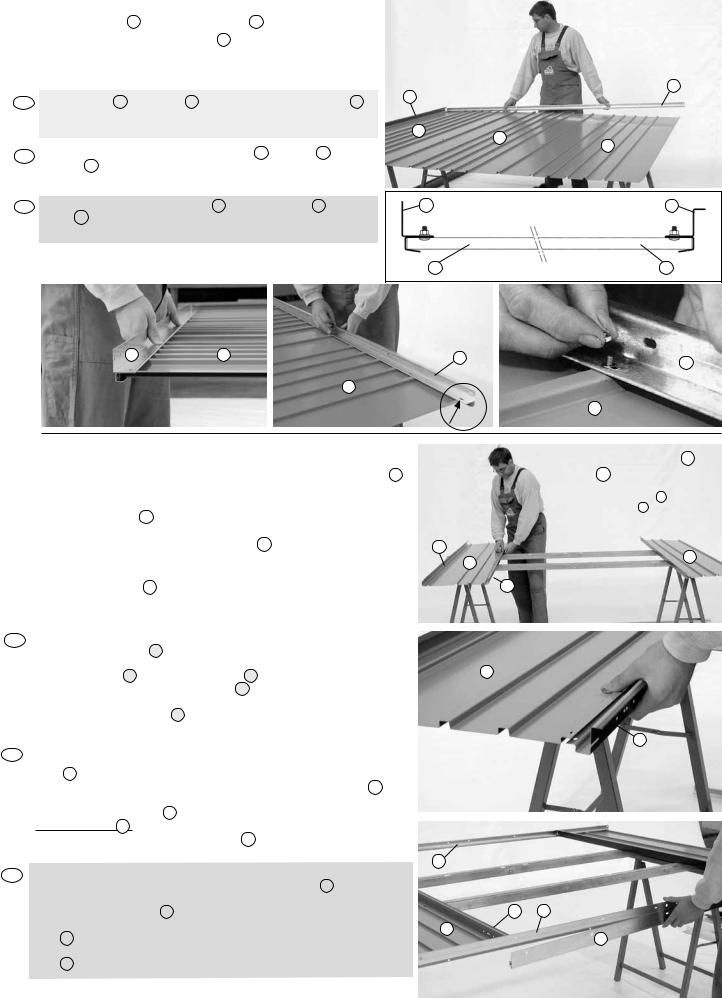
2. |
Schieben sie wie dargestellt das Boden |
profil A und das Kopfprofil B auf die |
|
|
Seitenwandelemente S . Befestigen Sie die Profile. |
Die Schraubverbindungen an den beiden seitlichen Enden werden erst später hergestellt. (siehe Pfeil!)
GB Slip the bottom A and the top B frames as shown onto the panels S . Fasten the top and bottom frames to the panels.
Do not yet fit the bolts at the ends (see arrow).
FFaites glisser comme sur l’image le profil de sol A et de tête B sur les éléments S . Fixez les profils. Les vis aux 2 extrémités des côtés ne seront fixées qu’à la fin du montage.
IInfilare e fissare il profilo a pavimento A e il profilo di testa B sulle pareti laterali S . Il fissaggio alle estremità va effettuato in un secondo momento (vedere freccia).
C |
|
|
B |
|
|
|
|
S |
S |
|
|
|
S |
|
|
|
|
|
|
A |
Innen / inside / intérieur / interno |
B |
|
|
|
||
S |
Außen / outside / extérieur / esterno |
S |
|
A S B B
S
S
No!
3. |
Die Vorderwand bauen Sie ebenso zusammen. Sie |
sparen lediglich den Platz für die Flügeltüren aus und |
|
montieren zusätzlich die beiden Türanschlagleisten D |
wie dargestellt. Bitte beachten Sie, daß Sie ab
|
Größe 3 die Türen auch außermittig positionieren können. Die |
|
Türbodenschwelle E befestigen Sie wie abgebildet. ACHTUNG: |
|
Sollten Sie beabsichtigen die Bodenschwellen-Rampe (Zubehör) |
|
einzubauen, darf die Türbodenschwelle E nicht montiert werden. |
|
Ein nachträglicher Ausbau ist schwierig. Weiters können Sie die 4 |
|
Scharnierunterteile gemeinsam mit den 4 Versteifungen an den |
|
Türanschlagleisten D montieren. => Beachten Sie die Prägungen |
|
auf den Scharnieren (L=links, R=rechts). |
|
|
GB |
Construct the front wall in a similar fashion. Only now leaving space for the doors, |
|
position both door posts D as shown. |
|
NOTE: from size 3 onwards, the doors can be positioned off-centre. You can now |
|
mount the door sill E onto the bottom frame A . If you intend to insert the Ramp |
|
(Accessories), please dont install the door sill E . It´s not easy to remove them after |
|
assembly. Furthermore you can position the 4 lower parts of the hinges along with |
|
the 4 braces to the door posts D . Pay attention to the markings on the hinges |
|
(L = Left, R = Right) |
|
|
FAssemblez de la même façon la paroi de devant en intégrant les portes. Laissez la place nécessaire pour les battants de porte et montez les deux battements de
porte D comme sur l’image. A partir de la taille 3, vous pouvez aussi monter les portes de façon excentrique. Vous pouvez déjà fixer le seuil de la porte E . Attention : Si vous souhaitez installer le seuil de rampe (accessoire), vous ne devez pas monter le seuil de porte E Démonter ultérieurement le seuil est difficile. Le profil de sol suffit A Vous pouvez monter les 4 parties inférieures des charnières avec leurs 4 renforts aux battements de porte D .
=> Respectez les inscriptions sur les charnières L= gauche, R= droite.
IMontare in modo analogo la parete frontale. Lasciare libero lo spazio previsto per le porte a battente e montare in aggiunta i profili di battuta porte D come illustrato. Vi ricordiamo che a partire dalla misura 3 le porte possono essere montate anche decentrate. Fissare la soglia E come raffigurato. ATTENZIONE: In caso di utilizzo della rampa da soglia (accessorio), non va assolutamente montata la soglia della
porta E . Smontare successivamente la soglia è difficile. Inoltre possono essere fissate le 4 parti inferiori delle cerniere con i relativi rinforzi sui profili di battuta porte D . Fare attenzione alla marcatura delle cerniere (L = sinistra, D = destra).
Bei den Größen 1 und 2 wird C direkt mit D verschraubt.
Per le misure 1 e 2 il pezzo C viene avvitato direttamente con D .
C
S1 |
S1 |
|
|
|
D |
S1
D
B
D A
S1
E
6

|
|
|
|
S1 |
|
D |
|
|
D |
S1 |
E |
|
unten |
|
|
|
|
|
|
|
|
|
|
bottom |
|
A |
|
|
bas |
|
|
A |
sotto |
|
|
|
|
|
|
|
S1 |
|
|
D |
A |
|
oben |
|
D |
top |
|
haut |
|
|
|
|
|
|
sopra |
S1 |
|
B |
4. |
Bauen sie nun die Rückwand mit den Seiten |
|
|
|
wänden zusammen. Die Enden der Kopfprofile |
|
B werden erst später mit Schrauben ver- |
|
bunden (s. Pfeil). Zuletzt montieren Sie das |
Vorderwandelement und richten die Wände rechtwinkelig ein. Für die Größen 2A – 7
bringen Sie an der linken und rechten oberen Ecke der Vorderwand die Haltewinkel für die Sturmhaken an. Die Kopf-/Bodenprofile der Rück-/ Vorderwand sollten über den Seitenwandprofilen liegen.
B C B
S S S S
S
GB |
Now assemble the back and the side wall elements together. Do not |
|
|
|
connect the ends of the top frames B together with bolts just yet (see |
|
|
|
|
|
|
|
|
|
|
arrow). Finally attach the front wall element and adjust all the walls to |
C |
|
|
|
be at right angles to one another. For the sizes 2A - 7 mount the brac- |
A |
A |
|
|
kets for the door hooks on the upper left and right corners of the front |
|
|
|
|
wall. The top and bottom frames of the front and back walls should |
|
|
|
|
overlap the profiles of the side walls (see detail) |
|
|
|
|
|
C |
|
|
F |
Assemblez maintenant la paroi arrière aux parois latérales. Les profils |
|
|
|
|
de tête seront vissés plus tard. Montez ensuite l’élément de la paroi de |
|
|
|
|
devant et ajustez les parois à angles droits. |
|
|
|
|
Pour les tailles 2A – 7, montez aux coins supérieurs gauche et droit de la |
S |
|
|
|
paroi de devant les angles de fixation pour les crochets des portes. Les |
No! |
B |
|
|
B |
|||
|
profils de tête et de sol des parois avant et arrière doivent reposer sur les |
|
||
|
S |
|
|
|
|
profils des parois latérales. |
|
|
|
|
|
|
|
|
|
|
|
|
|
I |
Collegare la parete posteriore con le pareti laterali. Fissare i terminali dei |
|
|
|
|
profili di testa B in un secondo momento (vedere freccia). Montare per |
|
|
|
|
ultimo la parete frontale e mettere in squadra le pareti. Per le misure 2A |
|
|
|
|
–7 montare negli angoli superiori destro e sinistro gli angolari per i ganci |
|
|
|
|
fermaporta. I profili a pavimento e i profili di testa della parete anteriore/ |
|
|
C |
|
posteriore devono trovarsi sopra i profili delle pareti laterali. |
|
|
|
|
|
|
|
|
|
|
A |
|
|
|
|
|
|
|
|
|
A |
|
|
7
 Loading...