

Page 1

Operating Manual
Translation of the original operating manual
KT (E6.1)
Cooling Incubator
with Peltier Refrigerating Technology and program controller
Model Model version Art. No.
KT 53 KT053-230V 9020-0311
KT 53-UL KT053UL-120V 9020-0312
KT 115 KT115-230V 9020-0313
KT 115-UL KT115UL-120V 9020-0314
KT 170 KT170-230V 9020-0289
KT 170-UL KT170UL-120V 9020-0310
BINDER GmbH
Address: Post office box 102, 78502 Tuttlingen, Germany Phone: +49 7462 2005 0
Fax: +49 7462 2005 100 Internet: http://www.b ind er -world.com
E-mail: info@binder-world.com Service Hotline: +49 7462 2005 555
Service Fax: +49 7462 2005 93 555 Service E-Mail: customerservice@binder-world.com
Service Hotline USA: +1 866 885 9794 or +1 631 224 4340 x3
Service Hotline Asia Pacif ic: +852 390 705 04 or +852 390 705 03
Service Hotline Russia and CIS: +7 495 988 15 16
Issue 11/2020 Art. No. 7001-0291
Page 2

Contents
1. SAFETY .................................................................................................................. 6
1.1 Personnel Qualification ....................................................................................................................... 6
1.2 Operating manual ................................................................................................................................ 6
1.3 Legal considerations ........................................................................................................................... 6
1.4 Structure of the safety instructions ...................................................................................................... 7
1.4.1 Signal word panel ..................................................................................................................... 7
1.4.2 Safety alert symbol ................................................................................................................... 7
1.4.3 Pictograms ................................................................................................................................ 8
1.4.4 Word message panel structure ................................................................................................. 8
1.5 Localization / position of safety labels on the chamber ...................................................................... 9
1.6 Type plate............................................................................................................................................ 9
1.7 General safety instructions on installing and operating the chambers ............................................. 11
1.8 Intended use ..................................................................................................................................... 12
1.9 Foreseeable Misuse .......................................................................................................................... 14
1.10 Residual Risks .................................................................................................................................. 15
1.11 Operating instructions ....................................................................................................................... 16
1.12 Measures to prevent accidents ......................................................................................................... 16
2. CHAMBER DESCRIPTION .................................................................................. 17
2.1 Chamber overview ............................................................................................................................ 18
2.2 Instrument panel ............................................................................................................................... 18
2.3 Chamber rear .................................................................................................................................... 19
3. COMPLETENESS OF DELIVERY, TRANSPORTATION, STORAGE, AND
LOCATION OF INSTALLATION .......................................................................... 20
3.1 Unpacking, and checking equipment and completeness of delivery ................................................ 20
3.2 Guidelines for safe lifting and transportation ..................................................................................... 21
3.3 Storage .............................................................................................................................................. 21
3.4 Location of installation and ambient conditions ................................................................................ 21
4. INSTALLATION OF THE EQUIPMENT ............................................................... 23
4.1 Spacer for wall distance .................................................................................................................... 23
4.2 Electrical connection ......................................................................................................................... 24
5. START UP ............................................................................................................ 25
5.1 Behavior when opening the door ...................................................................................................... 25
6. FUNCTIONAL OVERVIEW OF THE T4.12 CHAMBER CONTROLLER ............. 25
6.1 Menu structure .................................................................................................................................. 26
6.1.1 General menu ......................................................................................................................... 26
6.1.2 Quick menu ............................................................................................................................. 28
6.1.3 “User” menu ............................................................................................................................ 28
6.2 Operating modes ............................................................................................................................... 29
6.2.1 Activating the “control off” mode or change to “fixed value” operating mode ......................... 29
6.3 Performance during and after power failure ...................................................................................... 31
6.4 Information ........................................................................................................................................ 31
7. CONFIGURATION OF OPTIONAL EQUIPMENT ................................................ 32
7.1 Setting the optional door heating ...................................................................................................... 32
7.2 Turning on / off the optional interior socket ....................................................................................... 33
7.3 Switching on or off the optional zero-voltage relay control outputs .................................................. 34
7.4 Functional test of the optional alarm output ...................................................................................... 34
7.5 Switching on or off the optional object temperature display ............................................................. 35
KT (E6.1) 11/2020 Page 2/139
Page 3

8. SET-POINT ENTRY IN “FIXED VALUE” OPERATING MODE ........................... 35
8.1 Setting ranges: .................................................................................................................................. 35
8.2 Entering the set-points via “quick menu” ........................................................................................... 36
8.3 Entering the set-points via general menu ......................................................................................... 37
9. TIME PROGRAMS ............................................................................................... 39
9.1 Starting and running an existing time program ................................................................................. 40
9.2 Cancelling a running time program ................................................................................................... 43
9.3 Creating a new time program ............................................................................................................ 44
9.3.1 Section handling ..................................................................................................................... 46
9.3.2 Temperature setpoint .............................................................................................................. 47
9.3.3 Section duration ...................................................................................................................... 47
9.3.4 Repeating one or several sections within a time program ...................................................... 48
9.3.5 Tolerance range ...................................................................................................................... 49
9.3.6 Set-point ramp and set-point step modes ............................................................................... 50
9.3.7 Switching on or off the optional zero-voltage relay outputs .................................................... 52
9.3.8 Calling up the next parameter ................................................................................................. 53
9.3.9 Saving the time program and leaving the program editor ....................................................... 55
9.4 Program interruption ......................................................................................................................... 56
9.5 Deleting a time program .................................................................................................................... 57
10. WEEK PROGRAMS ............................................................................................. 58
10.1 Starting and running an existing week program................................................................................ 59
10.2 Cancelling a running week program ................................................................................................. 62
10.3 Creating a new week program .......................................................................................................... 62
10.3.1 Section handling ..................................................................................................................... 65
10.3.2 Temperature setpoint .............................................................................................................. 65
10.3.3 Day of the week ...................................................................................................................... 66
10.3.4 Time of the day ....................................................................................................................... 67
10.3.5 Activity of the shift-point .......................................................................................................... 67
10.3.6 Switching on or off the optional zero-voltage relay outputs .................................................... 68
10.3.7 Calling up the next parameter ................................................................................................. 68
10.3.8 Saving the week program and leaving the program editor ..................................................... 70
10.4 Deleting a week program .................................................................................................................. 71
11. KEY LOCK ........................................................................................................... 72
11.1 Directly activating the key lock function ............................................................................................ 73
11.2 Automatic key lock ............................................................................................................................ 74
11.3 Changing the password for unlocking the key lock ........................................................................... 75
12. GENERAL CONTROLLER SETTINGS ................................................................ 76
12.1 Setup wizard ..................................................................................................................................... 77
12.2 Date and time settings ...................................................................................................................... 78
12.3 Selecting the menu language of the T4.12 controller ....................................................................... 79
12.4 Setting display brightness ................................................................................................................. 79
12.5 Changing the temperature unit.......................................................................................................... 80
12.6 Defining the data recording rate ........................................................................................................ 80
12.7 Factory reset ..................................................................................................................................... 81
12.8 Network configuration ....................................................................................................................... 81
12.9 Display of the entire network configuration ....................................................................................... 85
12.10 Display and entry of the chamber configuration – for service purpose ............................................. 85
13. DATA TR AN SFER VIA U SB INTERFACE........................................................... 86
13.1 Exporting data to USB drive .............................................................................................................. 86
13.2 Importing data from USB drive .......................................................................................................... 87
14. NOTIFICATIONS AND ALARMS ......................................................................... 88
14.1 Notifications overview ....................................................................................................................... 88
KT (E6.1) 11/2020 Page 3/139
Page 4

Alarms overview ................................................................................................................................ 88
14.2
14.3 Alarm status ...................................................................................................................................... 89
14.4 Confirming a “set” alarm .................................................................................................................... 90
14.5 Alarm configuration and overview ..................................................................................................... 90
14.5.1 List of active alarms ................................................................................................................ 91
14.5.2 History – list of all alarms ........................................................................................................ 91
14.5.3 Activating, deactivating, and testing the alarm buzzer ........................................................... 92
14.5.4 Activating / deactivating all alarm functions ............................................................................ 93
14.5.5 Setting the delay time after opening the door ......................................................................... 93
15. EVENT LIST ......................................................................................................... 94
16. GRAPHICAL DISPLAY OF THE MEASURED VALUES ..................................... 95
16.1 Setting the sampling rate .................................................................................................................. 95
16.2 Defining the display range................................................................................................................. 96
16.3 Selecting the parameters .................................................................................................................. 97
17. TEMPERATURE SAFETY DEVICES ................................................................... 97
17.1 Overtemperature protective device (class 1) .................................................................................... 97
17.2 Overtemperature safety controller (temperature safety device class 3.1) ........................................ 97
17.2.1 Safety controller modes .......................................................................................................... 98
17.2.2 Setting the safety controller .................................................................................................... 98
17.3 Over- and undertemperature safety controller (temperature safety device class 3.3) (option) ...... 101
17.3.1 Safety controller modes ........................................................................................................ 102
17.3.2 Setting the Safety controller .................................................................................................. 102
18. NOTES ON REFRIGERATING OPERATION .................................................... 106
19. OPTIONS ............................................................................................................ 106
19.1 APT-COM™ 4 Multi Management Software (option) ...................................................................... 106
19.2 Data logger kit (option) .................................................................................................................... 106
19.3 Object temperature display with flexible Pt 100 temperature sensor (option) ................................ 107
19.4 Zero-voltage relay alarm output (option) ......................................................................................... 107
19.5 Zero-voltage relay control outputs (option) ..................................................................................... 109
19.6 Water protected internal socket (option) ......................................................................................... 109
20. CLEANING AND DECONTAMINATION ............................................................ 110
20.1 Cleaning .......................................................................................................................................... 111
20.2 Decontamination / chemical disinfection ......................................................................................... 112
21. MAINTENANCE AND SERVICE, TROUBLESHOOTING, REPAIR, TESTING . 113
21.1 General information, personnel qualification................................................................................... 113
21.2 Maintenance intervals, service ........................................................................................................ 114
21.3 Simple troubleshooting .................................................................................................................... 114
21.4 Sending the chamber back to BINDER GmbH ............................................................................... 117
22. DISPOSAL.......................................................................................................... 118
22.1 Disposal of the transport packing .................................................................................................... 118
22.2 Decommissioning ............................................................................................................................ 118
22.3 Disposal of the chamber in the Federal Republic of Germany ....................................................... 118
22.4 Disposal of the chamber in the member states of the EU except for the Federal Republic of
Germany.......................................................................................................................................... 119
22.5 Disposal of the chamber in non-member states of the EU ............................................................. 120
23. TECHNICAL DESCRIPTION .............................................................................. 121
23.1 Factory calibration and adjustment ................................................................................................. 121
23.2 Over current protection ................................................................................................................... 121
23.3 Definition of usable volume ............................................................................................................. 121
KT (E6.1) 11/2020 Page 4/139
Page 5

KT (E6.1) technical data .................................................................................................................. 122
23.4
23.5 Equipment and Options (extract) .................................................................................................... 123
23.6 Spare parts and accessories (extract) ............................................................................................ 124
23.7 KT / KT-UL 53 dimensions .............................................................................................................. 125
23.8 KT / KT-UL 115 dimensions ............................................................................................................ 126
23.9 KT / KT-UL 170 dimensions ............................................................................................................ 127
24. CERTIFICATES AND DECLARATIONS OF CONFORMITY ............................. 128
24.1 EU Declaration of Conformity.......................................................................................................... 128
24.2 Certificate for the GS mark of conformity of the “Deutsche Gesetzliche Unfallversicherung e.V.“
(German Social Accident Insurance) DGUV ................................................................................... 131
25. PRODUCT REGISTRATION .............................................................................. 133
26. CONTAMINATION CLEARANCE CERTIFICATE ............................................. 134
26.1 For chambers located outside the USA and Canada ..................................................................... 134
26.2 For chambers located in the USA and Canada .............................................................................. 137
KT (E6.1) 11/2020 Page 5/139
Page 6
Dear customer,
For the correct oper ation of the chambers, it is important t hat you r ead this op erating m anual com pletely
and carefully and observe all instructions as indicated. Failure to read, understand and follow the
instructions may result in personal injury. It can also lead to damage to the chamber and/or poor equipment
performance
1. Safety
1.1 Personnel Qualification
The chamber m ust only be installed, tested, and start ed up by personn el qualified for as sembly, startup,
and operation of the chamber. Qualified personnel are persons whose professional education, knowledge,
experience and knowledge of relevant standards allow them to assess, carry out, and identify any potential
hazards in the work as s igned to t hem. They must have been tra ine d an d i nstr uc t ed, a nd b e a uthorized, to
work on the chamber.
The chamber should only be operated b y laborator y personnel especially trained for this purpose and
familiar with all precautionary measures required for working in a laboratory. Observe the national
regulations on minimum age of laboratory personnel.
1.2 Operating manual
This operating m anual is part of the com ponents of delivery. Alwa ys keep it handy for referenc e in the
vicinity of the chamber. If selling the unit, hand over the operating manual to the purchaser.
To avoid injuries and damage observe th e safety instructions of the operating m anual. Failure to follow
instructions and safety precautions can lead to significant risks.
DANGER
Dangers due to failure to observe the ins truc tions and safety precautions.
Serious injuries and chamber damage. Risk of death.
Observe the safety instructions in this Operating Manual.
Follow the operating procedures in this Operating Manual.
Carefully read the complete operating instructions of the chamber prior to installing and
using the chamber.
Keep the operating manual for future reference
Make sure that all persons who use the chamber and its associated work equipment have
read and understood the Operating Manual.
This Operating Manu al is supplemented a nd updated as needed. Alwa ys use the mos t recent version of
the Operating Manual. When in doubt, call the BINDER Service Hotline for information on the up-todateness and validity of this Operating Manual.
1.3 Legal considerations
This operating manual is for informational purposes only. It contains information for correct and safe
installing, start-up, operation, decommissioning, cleaning and maintenance of the product. Note: the
contents and the product descr ibed are subj ect to cha nge with out not ice.
KT (E6.1) 11/2020 Page 6/139
Page 7
Understanding and observing the instructions in this operating manual are prerequisites for hazard-free use
and safety during operation and maintenance. Images are to provide basic understanding. They may
deviate from the actual version of the chamber. The actual scope of delivery can, due to optional or special
design, or due to recent technical changes, deviate from the information and illustrations in these
instructions this oper ating manual. In no event shall BINDER be held liable for any dam ages, direct or
incidental arising out of or related to the use of this manual.
This operating manual can not cover all conce ivable applications . If you would lik e additional inform ation,
or if special problem s arise that are not suff iciently addressed in th is manual, please ask your dealer or
contact us directly, e.g. by phone at the number located on page one of this manual
Furthermore, we emphasize that the contents of this operating manual are not part of an earlier or existing
agreement, descriptio n, or l ega l rel ati ons h ip, nor d o t h e y m odify such a relationship. Al l o bliga tio ns on the
part of BINDER derive from the respective purchase contract, which also contains the entire and exclusively
valid statement of warranty administration and the general terms and conditions, as well as the legal
regulations valid at the t ime the contract is concluded. The statements in this manual neit her au gment nor
restrict the contractual warranty provisions.
1.4 Structure of the safety instructions
In this operating manual, the following safety definitions and symbols indicate dangerous situations
following the harmonization of ISO 3864-2 and ANSI Z535.6.
1.4.1 Signal word panel
Depending on the probability of serious consequences, potential dangers are identified with a signal word,
the corresponding safety color, and if appropriate, the safety alert symbol.
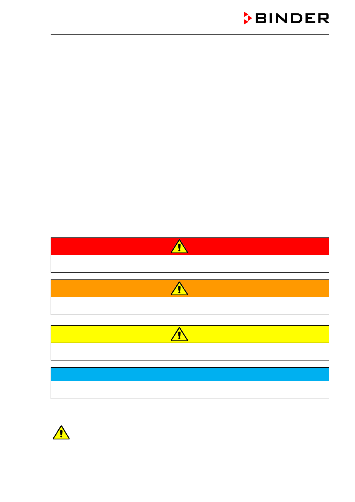
DANGER
Indicates an imminently hazardous situation that, if not avoided, will result in death or serious
(irreversible) injury.
WARNING
Indicates a potentially hazardous situation which, if not avoided, could result in death or serious
(irreversible) injury.
CAUTION
Indicates a potentially hazardous situation which, if not avoided, may result in moderate or minor
(reversible) injury.
NOTICE
Indicates a potentially hazardous situation which, if not avoided, may result in damage to the product
and/or its functions or of a property in its proximity.
1.4.2 Safety alert symbol
Use of the safety alert symbol indicates a risk of injury.
Observe all measures that are marked with the safety alert symbol in order to avoid death or
injury.
KT (E6.1) 11/2020 Page 7/139
Page 8
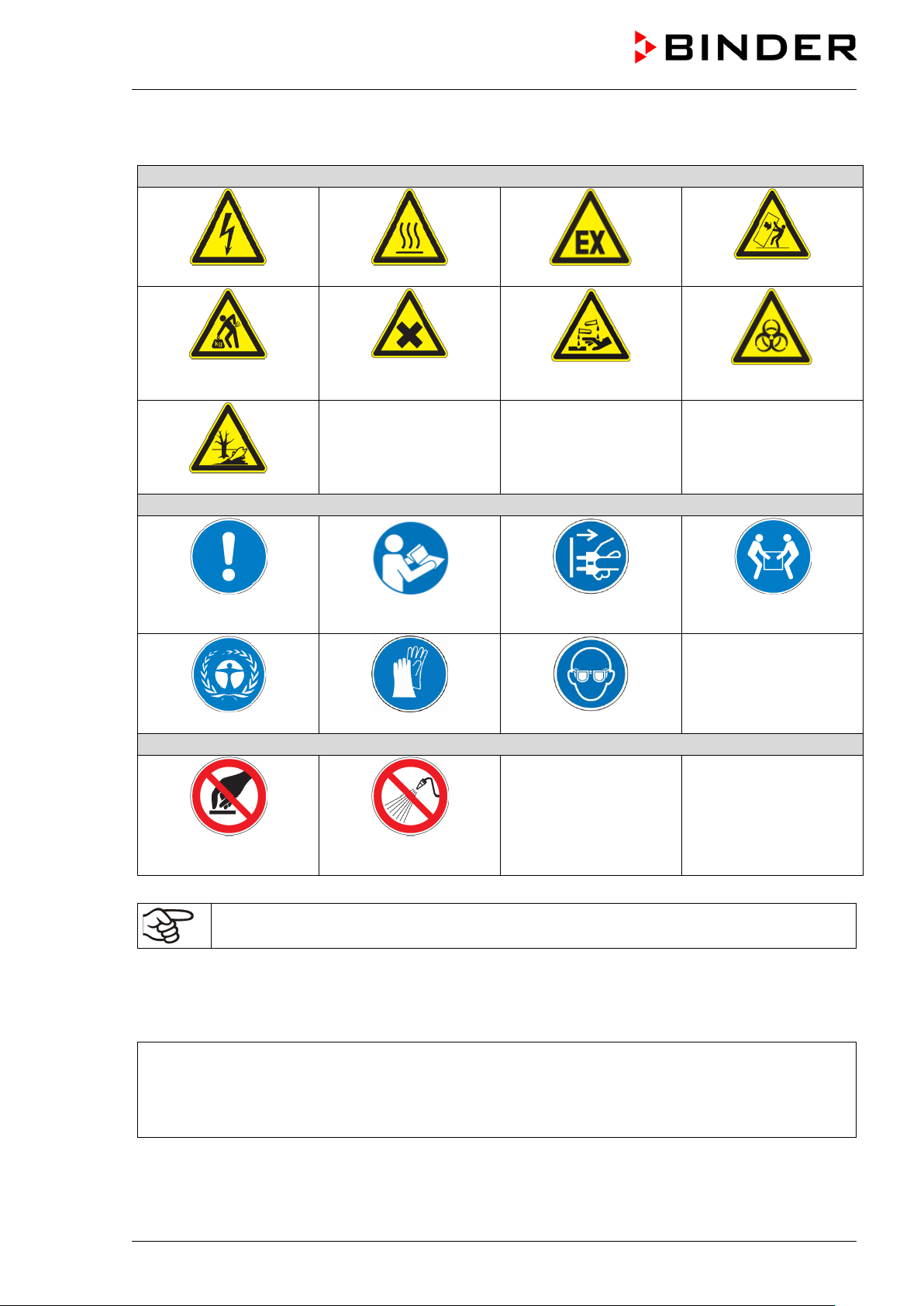
Warning signs
Electrical hazard
Hot surface
Explosive atmosphere
or chemical burns
Pollution Hazard
Mandatory action signs
instructions
plug
Environment protection
Wear protective gloves
Wear safety goggles
Prohibition signs
water
1.4.3 Pictograms
Lifting hazard
Mandatory regulation
Harmful substances
Read operating
Risk of corrosion and /
Disconnect the power
Stability hazard
Biohazard
Lift with several persons
Do NOT touch
Information to be observed in order to ensure optimum function of the product.
Do NOT spray with
1.4.4 Word message panel structure
Type / cause of hazard.
Possible consequences.
Instruction how to avoid the hazard: prohibition
Instruction how to avoid the hazard: mandatory action
Observe all other n otes and informat ion not necessarily em phasized in the sam e way, in order to a void
disruptions that could result in direct or indirect injury or property damage.
KT (E6.1) 11/2020 Page 8/139
Page 9
Pictograms (Warning signs)
Service label
Nominal temp.
100 °C
0,80 kW / 3,0 A
Thermoelectric cooli ng
212 °F
200-230 V / 50 Hz
Peltier
IP protection
20
200-230 V / 60 Hz
Safety device
DIN 12880
1 N ~
Class
3.1
Art. No.
9020-0289
Project No.
Built
2020
Cooling incubator
BINDER GmbH
www.binder-world.com
KT 170
Serial No. 00000000000000
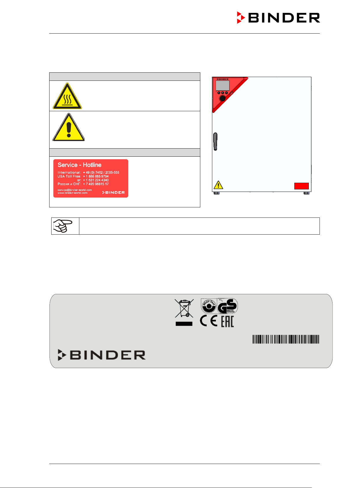
1.5 Localization / position of safety labels on the chamber
The following labels are located on the chamber:
Hot surface
• Inner glass door next to the glass door
handle
Read operating manual
• UL chambers: outer chamber door
• KT with optional interior socket: below
the interior socket
Figure 1: Position of labels on KT-UL
Keep safety labels complete and legible.
Replace safety labels that are no longer legible. Contact BINDER service for these replacements.
1.6 Type plate
The type plate is located on the left chamber side, on the bottom, right side.
Im Mittleren Ösch 5
78532 Tuttlingen / Germany
E6.1
Figure 2: Type plate (example of KT 170 regular chamber)
Made in Germany
KT (E6.1) 11/2020 Page 9/139
Page 10
Indications of the type plate
(example)
Information
BINDER
Manufacturer: BINDER GmbH
KT 170
Model
Cooling incubator
Device name
Serial No.
000000000000
Serial no. of the chamber
Built
2020
Year of construction
Nominal
100 °C
212 °F
IP protection
20
IP type of protection acc. to standard EN 60529
Temp. safety device
DIN 12880
Temperature safety device acc. to standard DIN 12880:2007
Class
3.1
Class of temperature safety device
Art. No.
9020-0289
Art. no. of the chamber
Project No.
---
Optional: Special application acc. to project no.
0,80 kW
Nominal power
3,0 A
Nominal current
200-230 V / 50 Hz
200-230 V / 60 Hz
1 N ~
Current type
Thermoelectric cooling Peltier
Peltier refrigerating technology
Symbol on the type plate
Information
LABORATORY EQUIPMENT
43KM
temperature
Nominal temperature
Nominal voltage range +/-10% at the indicated power
frequency
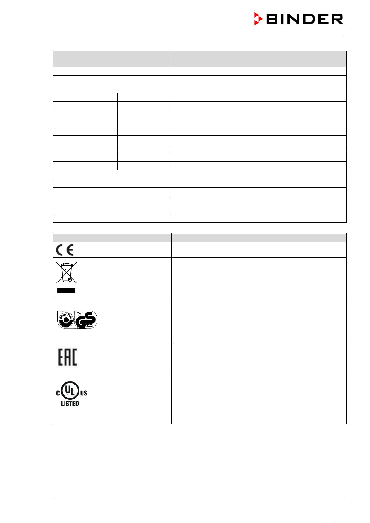
CE conformity marking
Electrical and electronic equipment manufactured / placed on
the market in the EC after 13 August 2005 and to be
disposed of in separate collection according to Directive
2012/19/EU on waste electrical and electronic equipment
(WEEE).
(KT-UL only)
GS mark of conformity of the “Deutsche Gesetzliche
Unfallversicherung e.V. (DGUV), Prüf- und
Zertifizierungsstelle Nahrungsmittel und Verpackung im
DGUV Test“ (German Social Accident Insurance (DGUV),
Testing and Certification Body for Foodstuffs and Packaging
Industry in DGUV Test). (Not valid for UL chambers)
The chamber is certified according to Customs Union
Technical Regulation (CU TR) for the Eurasian Economic
Union (Russia, Belarus, Armenia, Kazakhstan Kyrgyzstan).
The chamber is certified by Underwriters Laboratories Inc.
®
according to the following standards:
rd
• UL 61010-1, 3
• CAN/CSA-C 22.2 No. 61010-1, 3
Edition, 2012-05, Rev. 2015-07
rd
Edition, 201 2-05, Rev.
2015-07
rd
• IEC/EN 61010-1:2014, 3
Edition
KT (E6.1) 11/2020 Page 10/139
Page 11
1.7 General safety instructions on installing and operating the chambers
With regard to operating the chambers and to the installation location, please observe the local and national
regulations relevant for your country (for Germany: DGUV guidelines 213-850 on safe working in
laboratories, issued by the employers’ liability insurance association).
BINDER GmbH is only respons ible for th e safet y features of th e chamber provided sk illed elec tricians or
qualified personnel authorized by BINDER perform all maintenance and repair, and if components relating
to chamber safety are replaced in the event of failure with original spare parts.
To operate the chamber, use only original BINDER ac cessories or ac cessories f rom third-par ty suppliers
authorized by BINDER. The user is responsible for any risk caused by using unauthorized accessories.
NOTICE
Danger of overheating due to lack of ventilation.
Damage to the chamber.
∅ Do NOT install the chamber in unventilated recesses.
Ensure sufficient ventilation for dispersal of the heat.
Observe the prescribed minimum distances when installing the chamber (chap. 3.4)
Do not install or operate the chamber in hazar dous lo c ations .
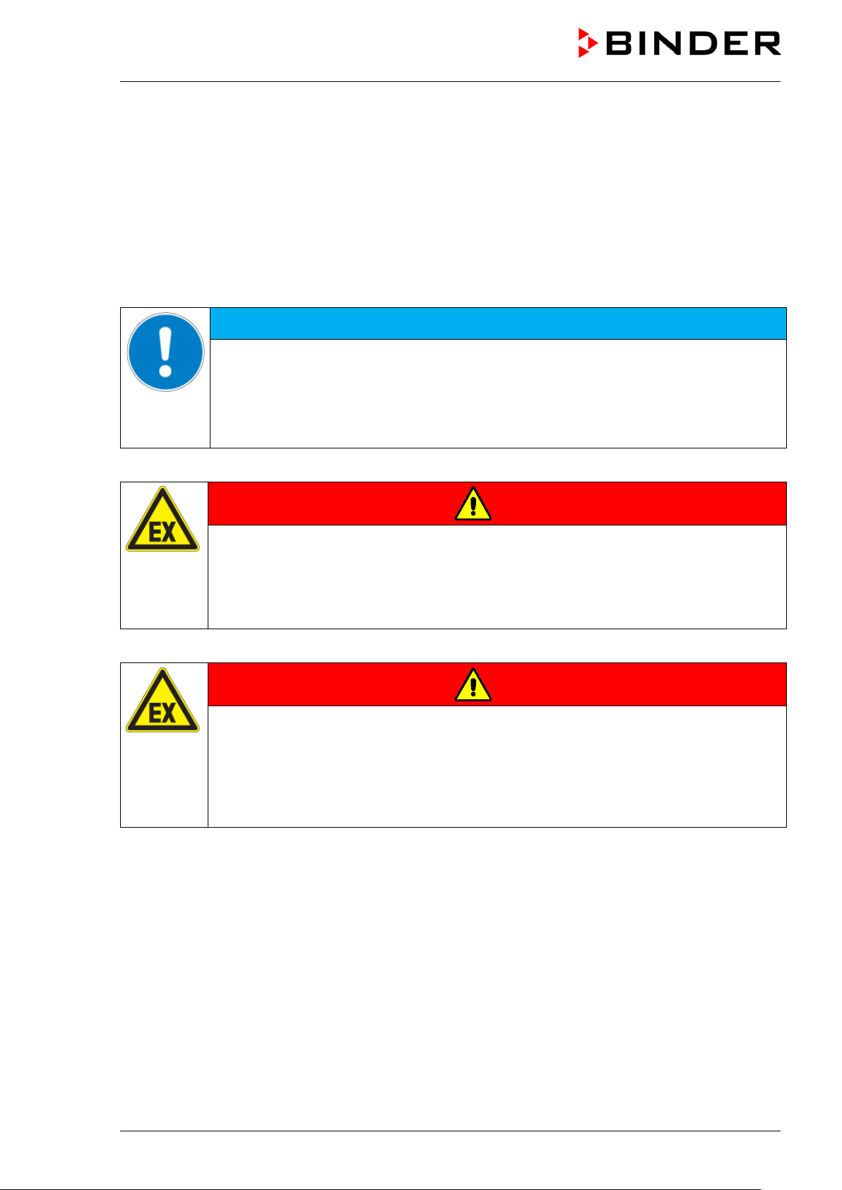
DANGER
Danger of explosion due to combustible du sts or explosive mixtures in the vicinity
of the chamber.
Serious injury or death from burns and / or explo sion pressure.
∅ Do NOT operate the chamber in potentially explosive areas.
KEEP combustible dust or air-solvent mixtures AWAY from the chamber.
The chamber does not dispose of any measures of explosion protection.
DANGER
Danger of explosion due to introduction of flammable or explosive substances in
the chamber.
Serious injury or death from burns and / or explo sion pressure.
∅ Do NOT introduce any substance into the chamber which is combustible or explosive at
working temperature.
∅ Do NOT introduce any combustible dust or air-solvent mixture in the inner chamber.
Any solvent contai ned in th e charging m aterial m ust not be explosive or inflammabl e. I.e., irres pective of
the solvent concentrati on in the steam room, NO explos ive mixture with air must f orm. The temperature
inside the cham ber m ust lie belo w the f lash point or belo w the su blim ation point of the ch arging mater ial.
Familiarize yourself with the physical and chemical properties of the charging material, as well as the
contained moisture constituent and its behavior with the addition of heat energy.
Familiarize yourself with any potential health risks caused by the charging material, the contained moisture
constituent or by reaction products which may arise during the temperature process. Take adequate
measures to exclude such risks prior to putting the chamber into operation.
KT (E6.1) 11/2020 Page 11/139
Page 12
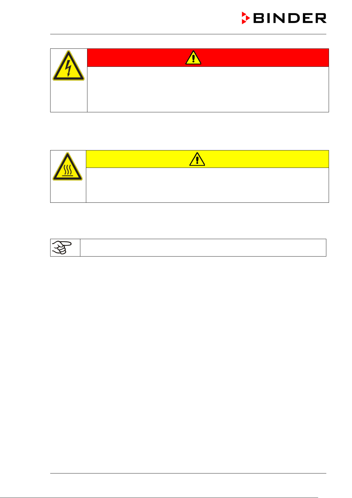
DANGER
Electrical hazard by water entering the chamber.
Deadly electric shock.
∅ The chamber must NOT become wet during operation, cleaning, or maintenance.
∅ Do NOT install the chamber in damp areas or in puddles.
Set up the chamber in a splash-proof manner.
The chambers were produced in accordance with VDE regulations and were routinely tested in accordance
to VDE 0411-1 (IEC 61010-1).
During and shortl y after operation, th e temperatur e of the inner s urfac es almos t equals the set-point. The
glass door, the glass door handles, and the inner chamber will become hot during operation.
CAUTION
Danger of burning by touching hot chamber parts during operation.
Burns.
∅ Do NOT touch the glass door, the glass door handles, the inner surfaces or the
charging material during oper atio n.
1.8 Intended use
Following the instructions in this operating manual and conducting regular maintenance work
(chap. 21.2) are part of the intended use.
Any use of the chambers that does not comply with the requirements specified in this Operating
Manual shall be considered improper use.
Other applications than those described in this chapter are not approved.
Use
Cooling incubators KT are suitab le for exac t conditioni ng of harmles s materials. Because of the ir precise
temperature accurac y these d evices ar e espec ially us eful for c ultivation of m icroorgan isms with a narro w
temperature optim um in a range of 4 °C / 39.2°F to 37 °C / 98.6°F. Main fields of app lication are t ests of
long-term stor age (e.g. at 4 °C / 39.2°F), ref rigerated incubat ion between 20 ° C / 68°F and 25 °C / 77°F
and incubation at 37 °C / 98.6°F (also with add iti on al int roduc t ion of heat) or with alter n ati ng temperatures
(e.g. 37 °C / 98.6°F and 4 °C / 39.2°F).
Requirements for the chamber load
Any solvent must not be explosive and flammable. A mixture of any component of the loading material with
air must NOT be explosive. The operating temperature must lie below the flash point or below the
sublimation point of the chargin g material. Any com ponent of the c harging m aterial must NO T be able to
release toxic gases.
The charging material shall not contain any corrosive ingredients that may damage the machine
components made of stain less steel, aluminum , and copper. Such ingr edients include in part icular acids
and halides. Any corrosive damage caused by such ingredients is excluded from liability by BINDER GmbH.
KT (E6.1) 11/2020 Page 12/139
Page 13
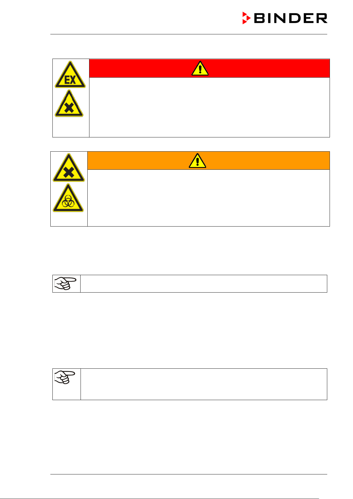
The chamber does not dispose of any measures of explosion protection.
DANGER
Explosion or implosion hazard and danger of poisoning through the introduction of
unsuitable loading material.
Poisoning. Serious injury or death from burns and / or explosion pressure.
∅ Do NOT introduce any substance combustible or explosive at working temperature into
the chamber, in particular no energy sources such as batteries or lithium-ion batteries.
∅ NO explosive dust or air-solvent mixture in the inner chamber.
∅ Do NOT introduce any substance which could lead to release of toxic gases.
Contamination of the chamber by toxic, infectious or radioactive substances must be prevented
WARNING
Danger of intoxication and infection through contamination of the chamber with
toxic, infectious or radioactive substances.
Damages to health.
Protect the interior of the chamber from contamination by toxic, infectious or radioactive
substances.
Take suitable protective measures when introducing and removing toxic, infectious or
radioactive material
In case of foreseeable use of the chamber there is no risk for the user through the integration of the chamber
into systems or by special environmental or operating conditions in the sense of EN 61010-1:2010. For this,
the intended use of the chamber and all its connections must be observed.
Medical devices
The chambers are not classified as medical devices as defined by the Medical Device Directive 93/42/EEC.
Due to the special demands of the Medical Device Directive (MDD), these chambers are not
qualified for sterilization of medical devices as defined by the directive 93/42/EWG.
Personnel Requirements
Only trained personnel with knowledge of the Operating Manual can set up and install the chamber, start it
up, operate, clean, and tak e it out of op eration. Ser vic e and repairs call for f urther techn ical req uirem ents
(e.g. electrical know-how), as well as knowledge of the service manual.
Installation site requirements
The chambers are designed for setting up inside a building (indoor use).
The requirements des cribed in the Operating Manua l for installation site and ambient conditions (Chap.
3.4) must be met.
WARNING: If customer should use a BINDER chamber running in non-supervised
continuous operation, we strongly recommend in case of inclusion of irrecoverable specimen
or samples to split such specimen or samples and store them in at least two chambers, if
this is feasible.
KT (E6.1) 11/2020 Page 13/139
Page 14

1.9 Foreseeable Misuse
Other applications than those described in chap. 1.8 are not approved.
This expressly incl udes the following misuses (the list is not exhaustive), which pos e risks despite the
inherently safe construction and existing technical safety equipment:
• Non-observance of Operating Manual
• Non-observance of information and warnings on the chamber (e.g. control unit messages, safety
identifiers, warning signals)
• Installation, startup, operation, maintenance and repair by untrained, insufficiently qualified, or
unauthorized personnel
• Missed or delayed maintenance and testing
• Non-observance of traces of wear and tear
• Insertion of materials excluded or not permitted by this Operating Manual.
• Non-compliance with the admissible parameters for processing the respective material.
• Installation, testing, service or repair in the presence of solvents
• Installation of replacement parts and use of accessories and operating reso urces not specified and
authorized by the manufacturer
• Installation, startup, operation, maintenance or repair of the chamber in absence of operating
instructions
• Bypassing or c hang in g pr ot ec tive systems, operation of the c hamber without the designated pr otec t ive
systems
• Non-observance of messages regarding cleaning and disinfection of the chamber.
• Spilling water or clean ing agent on the cham ber, water penetrating into the c hamber dur ing operat ion,
cleaning or maintenance.
• Cleaning activity while the chamber is turned on.
• Operation of the chamber with a damaged housing or damaged power cord
• Continued operation of the chamber during an obvious malfunction
• Insertion of objects, particularly metallic objects, in louvers or other openings or slots on the chamber
• Human error (e.g. insufficient experience, qualification, stress, exhaustion, laziness)
To prevent these and other risks fr om incorrect operati on, the operator s hall issue operating instruc tions.
Standard operating procedures (SOPs) are recommended.
KT (E6.1) 11/2020 Page 14/139
Page 15

1.10 Residual Risks
The unavoidable design features of a chamber, as well as its proper field of application, can also pose risks,
even during correct operation. These residual risks include hazards which, despite the inherently safe
design, existing technical protective equipment, safety precautions and supplementary protective
measures, cannot be ruled out.
Messages on the chamber and in the Operating Manual warn of residual risks. The consequences of these
residual risks and the measures required to prevent them are listed in the Operating Manual. Moreover, the
operator must take measures to minimize hazards from unavoidable residual risks. This includes, in
particular, issuing operating instructions.
The following list s ummarizes the hazar ds against which this Operating Manua l and the Service Manua l
warn, and specifies protective measures at the appropriate spots:
Unpacking, Transport, Installati on
• Sliding or tilting the chamber
• Setup of the chamber in unauthorized areas
• Installation of a damaged chamber
• Installation of a chamber with damaged power cord
• Inappropriate site of installation
• Missing protective conductor connection
Normal operation
• Assem bly errors
• Contact with hot surfaces on the housing
• Contact with hot surfaces in the interior and inside of doors
• Emission of non-ionizing radiation from electrical operating resources
• Contact with live parts in normal state
Cleaning and Decontamination
• Penetration of water into the chamber
• Inappropriate cleaning and decontamination agents
• Enclosure of persons in the interior
Malfunction and Damage
• Continued oper atio n of th e c ham ber during an ob vious m alfunc tion or out age of the he ating or cooling
system
• Contact with live parts during error status
• Operation of a unit with damaged power cord
Maintenance
• Maintenance work on live parts.
• Execution of maintenance work by untrained/insufficiently qualified personnel
• Electrical safety analysis during annual maintenance not performed
Trouble-shooting and Repairs
• Non-observance of warning messages in the Service Manual
• Trouble-shooting of live parts without specified safety measures
KT (E6.1) 11/2020 Page 15/139
Page 16
• Absence of a plausibility check to rule out erroneous inscription of electrical components
• Performance of repair work by untrained/insufficiently qualified personnel
• Inappropriate repairs which do not meet the quality standard spec if ied b y BINDER
• Use of replacement parts other than BINDER original replacement parts
• Electrical safety analysis not performed after repairs
1.11 O perating instructions
Depending on the a pplicati on and loc ation of the chamber, the operator of the chamber mus t provide th e
relevant information for safe operation of the chamber in a set of operating instructions.
Keep these operating instructions with the chamber at all times in a place where they are
clearly visible. They must be comprehensible and written in the language of the employees.
1.12 Measures to prevent accidents
The operator of the chamber must observe the following rule: “Betreiben von Arbeitsmitteln. Betreiben von
Kälteanlagen, Wärmepumpen und Kühleinrichtungen“ (Operation of work equipment. Operation of
refrigeration systems, heat pumps and refrigeration equipment) (GUV-R 500 chap. 2.35) (for Germany).
The manufacturer took the follo wing m eas ures to prevent ign iti on and ex plos io ns :
• Indications on the type plate
See operating manual chap. 1.6.
• Operating manual
An operating manual is available for each chamber.
• Overtemperature monitoring
The chamber is equipped with a temperature display, which can be read from outside.
The chamber is equipped with an addition al saf ety contr oller ( tem perature s afet y device clas s 3.1 acc .
to DIN 12880:2007). Visual and audible (buzzer) signals indicate temperature exceeding.
• Safety, measurement, and control equipment
The safety, measuring, and control equipment is easily accessible.
• Electrostatic ch arg e
The interior parts are grounded.
• Non-ionizing radiation
Non-ionizing radiation is not intentionally produced, but released only for technical reasons by electrical
equipment (e.g. elec tr ic motors, power cables, sol eno i ds) . The machine has no permanent magnets. If
persons with active im plants (e.g. pacemakers, def ibrillators) keep a safe distance (distance of field
source to implant) of 30 cm, an influence of these implants can be excluded with high probability.
• Protection against touchable surfaces
Tested according to EN ISO 13732-1:2008.
• Floors
See operating manual chap. 3.4 for correct installation
KT (E6.1) 11/2020 Page 16/139
Page 17

• Cleaning
See operating manual chap. 21.3.
• Examinations
The chamber has been inspected by the “Deutsche Gesetzliche Unfallversicherung e.V. (DGUV)
(German Social Accident Insurance (DGUV)” (German Social Accident Insurance (DGUV), Testing and
Certification Body for Food stuffs and Pack aging Indus try in DGU V Test) and bears the GS mark. (Not
valid for UL chambers)
®
UL units only: The cham ber is certified by Underwr iters Laboratories Inc.
rd
standards: UL 61010-1, 3
2012-05, Rev. 2015-07; IEC/EN 61010-1:2014, 3
Edition, 2012-05, Rev. 2015-07; C AN/CS A-C22.2 N o. 61010-1, 3rd Edition,
rd
Edition
accord-ing to the following
2. Chamber description
A high level of precision, reliability, and safety for all growth parameters ensures optimum incubation
conditions. Moreover , the KT cooling i ncubator is designed f or maximum usability – even in continuous
operation year after year. It fulfills all technical and application-specific requirements arising in
experimentation such as in the areas of biotechnology, medicine, the nutrition industry, pharmaceutical and
cosmetics industries, botany, and zoology.
Two important temperature technologies have been combined to achieve perfect temperature control. The
Peltier refrigerating system, in conjunc tion with the APT .line™ preheating chamber technology, satisf ies
the unique prerequisites for attaining highly-precise temperature control and particularly short recovery
times after opening the door.
The refrigerating s ystem is dis tingu ished b y direc t, pr ec ise, and r apid tem perature conduct ion . Due to the
Peltier cooling, s hocks are om itted which would occ ur during start and stop of c onventional refrigerat ion
systems with a compressor.
The APT.line™ preheating chamber system ensures high level of spatial and time-based temperature
precision, thanks to the direct and distributed air circulation into the interior. This is especially important for
maintaining temper atures – especially with full cham bers – and for rapid restor ation of optimum growth
conditions after ope ning the door. The inner glass door ensures that the tem perature remains constant
when observing the incubation process. The air turbine supports exact attainment and maintenance of the
desired temperature accuracy. The fan speed is digitally adjustable. The heating and refrigerating systems
are microprocess or regulated to a te nth of a degree. In addition, the chamber provides alm ost unlimited
possibilities for adaptation to individual customer requirements based upon extensive programming options
and on the week program timer and real time clock of the controller.
All chamber f unctions are easy and comf ortable to us e thanks to the ir clear arra ngement. Maj or features
are easy cleaning of all chamber parts and avoidance of undesired contamination.
The inner chamber , the pre-heating cham ber and the interior si de of the doors a re all made of stainles s
steel V2A (German material no. 1.4301, US equivalent AISI 304). The housing is RAL 7035 powder-coated.
All corners and edges are also completely coated.
The chambers come equipped with an Ethernet interfac e for computer comm unication, e.g. via the APTCOM™ 4 Multi Management Software (option, chap. 19.1). For further options, see chap. 23.5.
Temperature range with an ambient temperature of +22 °C +/- 3 °C / 71.6 °F +/- 5.4 °F:
+4 °C / 23 °F up to +100 °C / 212 °F
Fan speed range with temperature values from 4 °C up to 70 °C: 40 % up to100 %
Fan speed with temperature values above 70 °C: 100 %
KT (E6.1) 11/2020 Page 17/139
Page 18
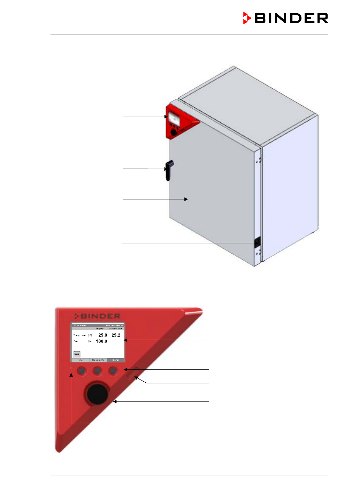
2.1 Chamber overview
Instrument panel with
microprocessor controller
T4.12 and USB interface
Door handle
Chamber door
Main power switch
2.2 Instrument panel
Figure 3: Cooling incubator KT (example: model KT 170)
5,7" controller display
Context-sensitive buttons
USB interface
Operating button
Pilot lamp: ready for operation
Figure 4: Instrument panel with microprocessor controller T4.12 and USB interface
KT (E6.1) 11/2020 Page 18/139
Page 19
(7) (8)
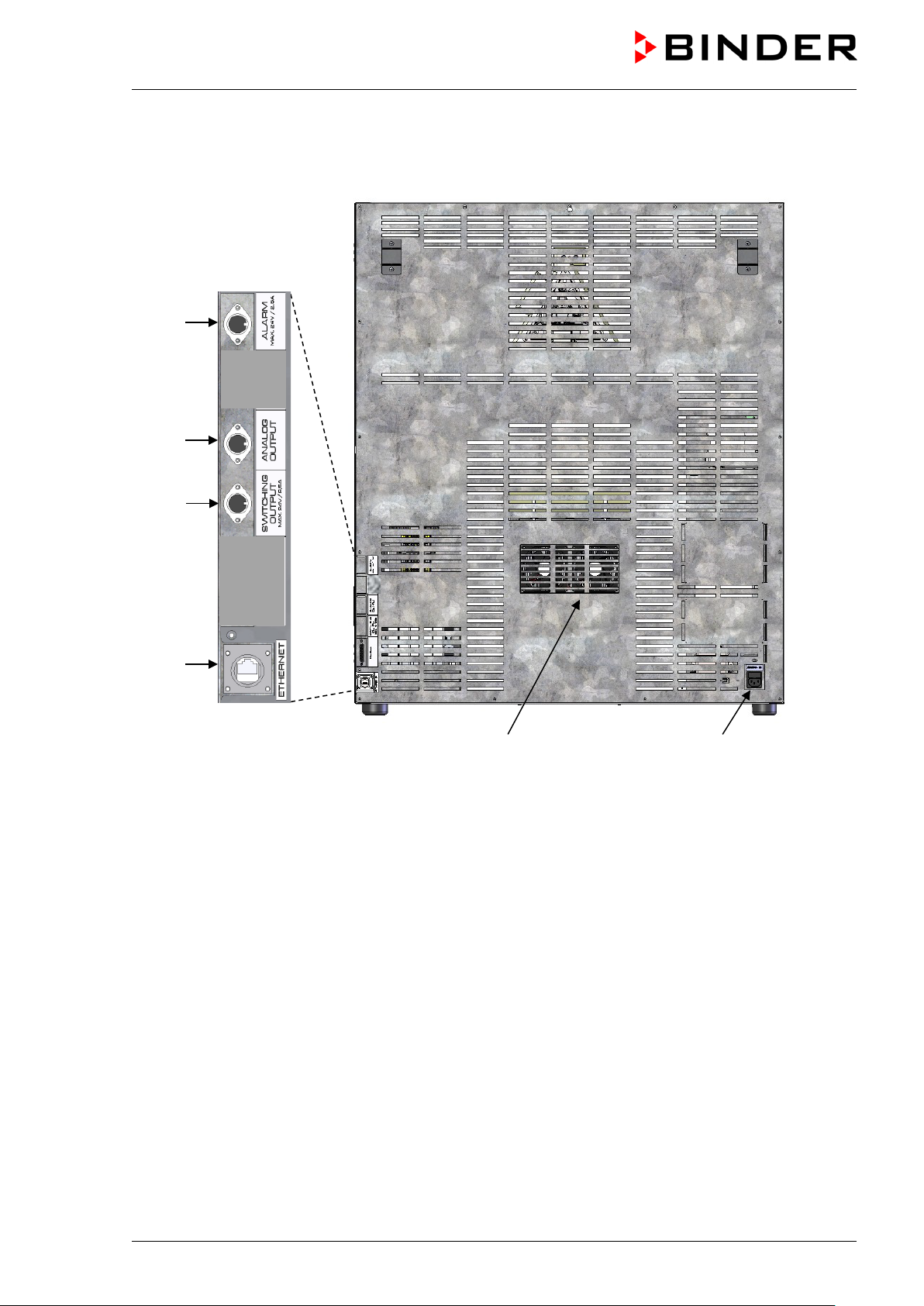
2.3 Chamber rear
(1)
(3)
(4)
(6)
Figure 5: Chamber rear with position of options (example KT 170)
(1) DIN-socket for zero-voltage relay alarm outputs (option)
(2) (not used)
(3) DIN socket for analog output 4-20 mA (option)
(4) DIN-socket for zero-voltage relay control outputs (option)
(5) (not used)
(6) Ethernet interface for computer communication
(7) Peltier fan grid
(8) Socket for IEC connector plug with power cable
KT (E6.1) 11/2020 Page 19/139
Page 20
nd 115 from the pa llet with the aid of four peopl e in the area of
3. Completeness of delivery, transportation, storage, and location of
installation
3.1 Unpacking, and checking equipment and completeness of delivery
After unpacking, p lease check the chamber and its optional acces sories, if any, based on the del ivery
receipt for completenes s and for transportation damage. Inf orm the carrier immediately if tr ansportation
damage has occurred.
The final tests of the manufacturer may have caused traces of the shelves on the inner surfaces. This has
no impact on the function and performance of the chamber.
Please remove any transportati on protection devices and adhes ives in/on the chamber and on the do ors
and remove the operating manuals and accessory equipment.
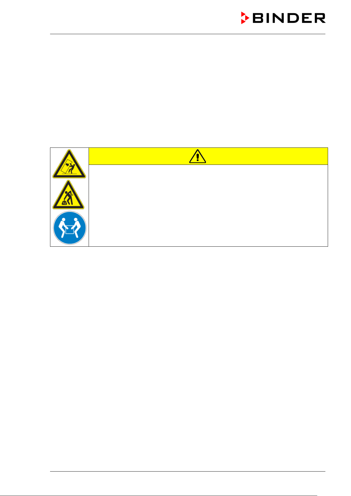
CAUTION
Risk of injury and damages by lifting heavy loads and by sliding or tilting of the
chamber due to improper lifting.
Injuries, damage to the chamber.
Do NOT lift or transport the chamber using the door or the door handle.
Lift chambers size 53 a
all 4 chamber feet.
Lift chambers size 170 from the pallet with the aid of six people in the area of all 4
chamber feet.
If you need to return the chamber, please use the original packing and observe the guidelines for safe lifting
and transportation (chap. 3.2).
For disposal of the transport packing, see chap. 22.1.
Note on second-hand chambers (Ex-Demo-Units):
Second-hand chambers are chambers that were use d for a short time for tests or exhib itions. They are
thoroughly tested before resale. BINDER ensures that the chamber is technically sound and will work
flawlessly.
Second-hand chambers are marked with a sticker on the chamber door. Please remove the sticker before
commissioning the chamber.
KT (E6.1) 11/2020 Page 20/139
Page 21
NOTICE
3.2 Guidelines for safe lifting and transportation
After operation, please observe the guidelines for temporary decommissioning (chap. 22.2).
CAUTION
Risk of injury and damages by lifting heavy loads and by sliding or tilting of the
chamber due to improper transportation.
Injuries, damage to the chamber.
Transport the chamber in its original packaging only.
For moving or shipping, secure the chamber with transport straps.
Do NOT lift or transport the chamber using the door or the door handle.
Lift the chamber size 53 and 115 at the four lower corners with the aid of 4 people and
place it on a rolling pallet.
Lift the chamber size 170 at the four lower corners with the aid of 4 people and place it
on a rolling pallet.
Permissible ambient temperature range during transport: 10 °C / 14°F to +60 °C / 140°F.
You can order transport packing for moving or shipping purposes from BINDER service.
3.3 Storage
Intermediate storage of the chamber is possible in a closed and dr y room. Observe the guidelines for
temporary decommissioning (chap. 22.2).
• Permissible ambient temperature range during storage: -10 °C / 14°F to +60 °C / 140°F.
• Permissible ambient humidity: max. 70 % r.h., non-condensing
When after storage in a cold location you transfer the chamber to its warmer installation site, condensation
may form. Befor e s tart -up, wait at le as t o ne ho ur un ti l t he c hamber has attained a mbient temperature and
is completely dry.
3.4 Location of installation and ambient conditions
Set up the chamber on a flat, even surface, free from vibration, in a well-ventilated, dry location and align it
using a spirit level. The site of installation must be capable of supporting the chamber’s weight (see
technical data, chap. 23.4). The chambers are designed for setting up inside a building (indoor use).
Danger of overheating due to lack of ventilation.
Damage to the chamber.
∅ Do NOT install the chamber in unventilated recesses.
Ensure sufficient ventilation for dispersal of the heat.
Observe the prescribed minimum distances when installing the chamber.
KT (E6.1) 11/2020 Page 21/139
Page 22
Do not install or operate the chamber in potentially explosive areas.
DANGER
Danger of explosion due to combustible du sts or explosive mixtures in the vicinity
of the chamber.
Serious injury or death from burns and / or explo sion pressure.
∅ Do NOT operate the chamber in potentially explosive areas.
KEEP explosive dust or air-solvent mixtures AWAY from the vicinity of the chamber.
Ambient conditions
• Permissible ambient temperature range during operation: +18 °C / 64.4 °F to +25 °C / 77 °F.
At elevated ambient temperature values, fluctuations in temperature can occur.
The ambient temperature should not be substantially higher than the indicated ambient
temperature of +22 °C +/- 3 °C / 71.6 °F ± 5.4 °F to which the specified technical data
relates. Deviations from the indicated data are possible for other ambient conditions.
Lower values of the temperature range indicated in the technical data are valid at an
ambient temperature of max. 25 °C / 77 °F.
With each degree of ambient temperature > +25 °C / 77°F, the refrigeration power
decreases by 1.5 K.
• Permissible ambient humidity: 70 % r.h. max., non-condensing.
When operating the chamber at temperature set-points below ambient temperature, high ambient
humidity may lead to condensation on the chamber.
• Installation height: max. 2000 m / 6.6 ft. above sea level.
Minimum distances
• When placing several chambers of the same size side by side, maintain a minimum distance of 250 mm
/ 9.84 in between each chamber.
• Wall distances (minimum distances): rear 100 mm / 3.94 in, sides 240 mm / 9.45 in.
• Spacing above the chamber of at least 100 mm / 3.94 in must also be maintained
Stacking
Two devices of the following sizes can be piled on top of each other:
• KT 53 on KT 53 or KT 115 or KT 170
• KT 115 on KT 115 or KT 170
• KT 170 on KT 170
Place rubber pads under all four feet of the upper chamber to prevent the device from slipping.
NOTICE
Danger of sliding or tilting of the upper chamber when stacking.
Damage to the chambers.
When stacking, place rubber pads under all four feet of the upper chamber.
Other requirements
To completely separat e the chamber f rom the power s upply, you m ust disconnect the power p lug. Install
the chamber in a way that the power plug is easily accessible and can be easily pulled in case of danger.
For the user there is no risk of temporary overvoltages in the sense of EN 61010-1:2010.
KT (E6.1) 11/2020 Page 22/139
Page 23
With an increased amount of dust in the ambient air, clean the Peltier fan grid (7) by suction or b lowing
several times a year.
Avoid any conductive dust in the ambiance according to the chamber layout complying with pollution degree
2 (IEC 61010-1).
4. Installation of the equipme nt
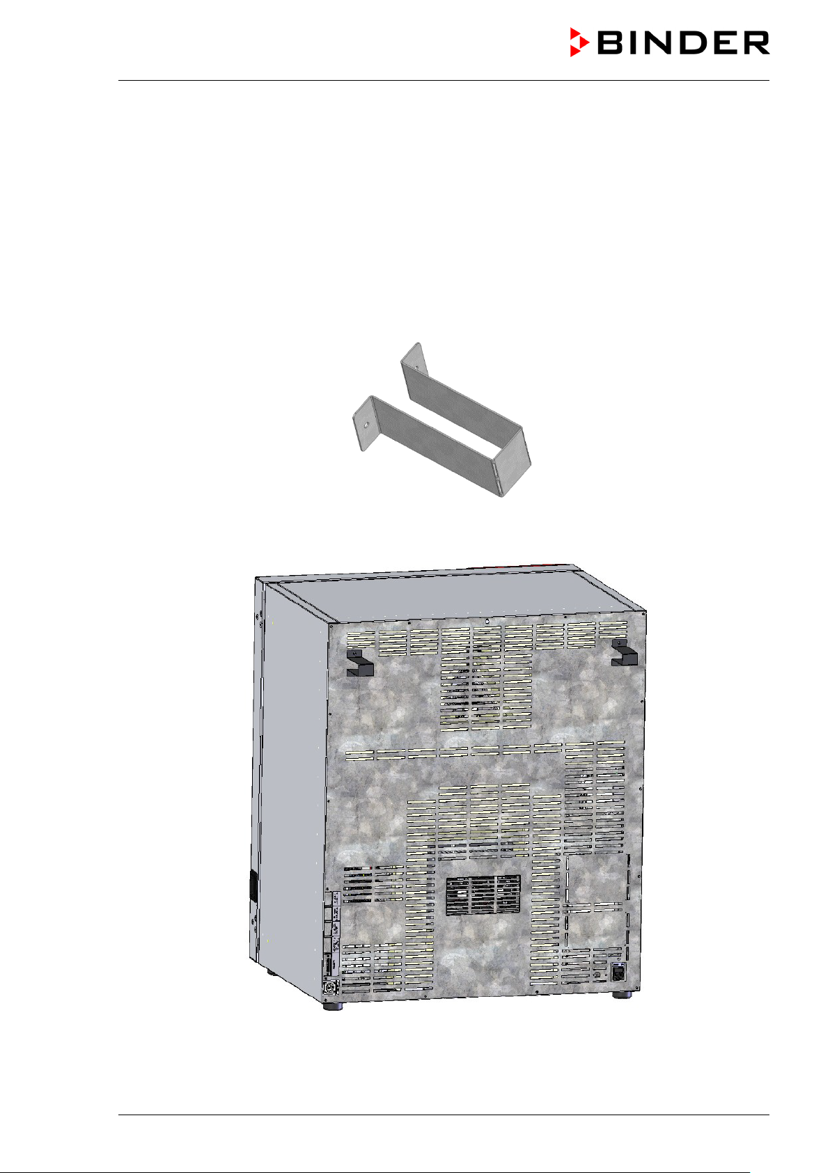
4.1 Spacer for wall distance
Please fix both spacers with the supplied screws at the chamber rear. This serves to ensure the prescribed
minimum distance to the rear wall of 100 mm / 3.94 in.
Figure 6: Spacer for wall distance
Figure 7: KT 170 rear with mounted spacers
KT (E6.1) 11/2020 Page 23/139
Page 24
KT 53
KT 170
KT 53-UL
KT 170-UL
NOTICE
4.2 Electri cal co nn ect io n
The chambers are supplied ready for connection. They come with an IEC connector plug.
Model Power plug
KT 115
KT 115-UL
• The domes tic socket must also provide a protec tive conductor. Make s ure that the connection of the
protective conductor of the domestic installations to the chamber’s protective conductor meets the latest
technology. The protective conductors of the socket and plug must be compatible!
Shock-proof plug
NEMA 5-15P
Nominal voltage ± 10% at the
indicated power frequency
200-230 V at 50 Hz
200-230 V at 60 Hz
100-120 V at 50 Hz
100-120 V at 60 Hz
Current
type
1N~ 10 A
1N~ 10 A
Chamber
fuse
DANGER
Electrical hazard due to missing protective conductor connection.
Deadly electric shock.
Make sure that the chamber’s power plug and the power socket match and
securely connect the electrical protective conductors of the chamber and the house
installation.
• Only use original connection cables from BINDER according to the above specification.
• Prior to con nection and s tar t-up, chec k the po wer su ppl y voltag e. Com pare th e v alues to t he sp ecif ied
data located on the chamber’s type plate (left chamber side, bottom right-hand, see chap. 1.6).
Danger of incorrect power supply voltage due to improper connection.
Damage to the chamber.
Check the power supply voltage before connection and start-up.
Compare the power supply voltage with the data indicated on the type plate.
• When connect ing, please o bserve the regul ations spec ified by the local e lectricity s upply com pany as
well as the local or national electrical regulations (VDE directives for Germany).
• Observe a sufficient current protection according to the number of devices that you want to operate. We
recommend the use of a residual current circuit breaker.
• Pollution degree (acc. to IEC 61010-1): 2
• Over-voltage category (acc. to IEC 61010-1): II
See also electrical data (chap. 23.4).
To completely separate the chamber from the power supply, you must disconnect the power
plug. Install the chamber in a way that the power plug is easily accessible and can be easily
pulled in case of danger.
KT (E6.1) 11/2020 Page 24/139
Page 25
5. Start up
After connecting the e lect ri c al su pply (chap. 4.2) turn on the chamber by the main power sw itch. The pilot
lamp shows the chamber is ready for operation.
Observe a delay time of about 30s between turning Off and On again. Otherwise an
initialization problem may occur.
Note that the cham ber is in stand-by mode when the main power s witch has bee n turned on and yet the
controller display is dark. Turn on the chamber by pressing any controller button.
Warming chambers may release odors in the first few days after commissioning. This is not a quality defect.
To reduce odors quick ly we recomm end heating up the chamber to its nominal tem perature for one day
and in a well-ventilated location.
WARNING: If customer should use a BINDER chamber running in non-supervised
continuous operation, we strongly recommend in case of inclusion of irrecoverable specimen
or samples to split such specimen or samples and store them in at least two chambers, if
this is feasible.
5.1 Behavior when opening the door
When you open the door, heating and fan turn off. After a delay time of von 60 seconds (KT 53), 40 seconds
(KT 115) or 20 seconds (KT 170) they turn on again.
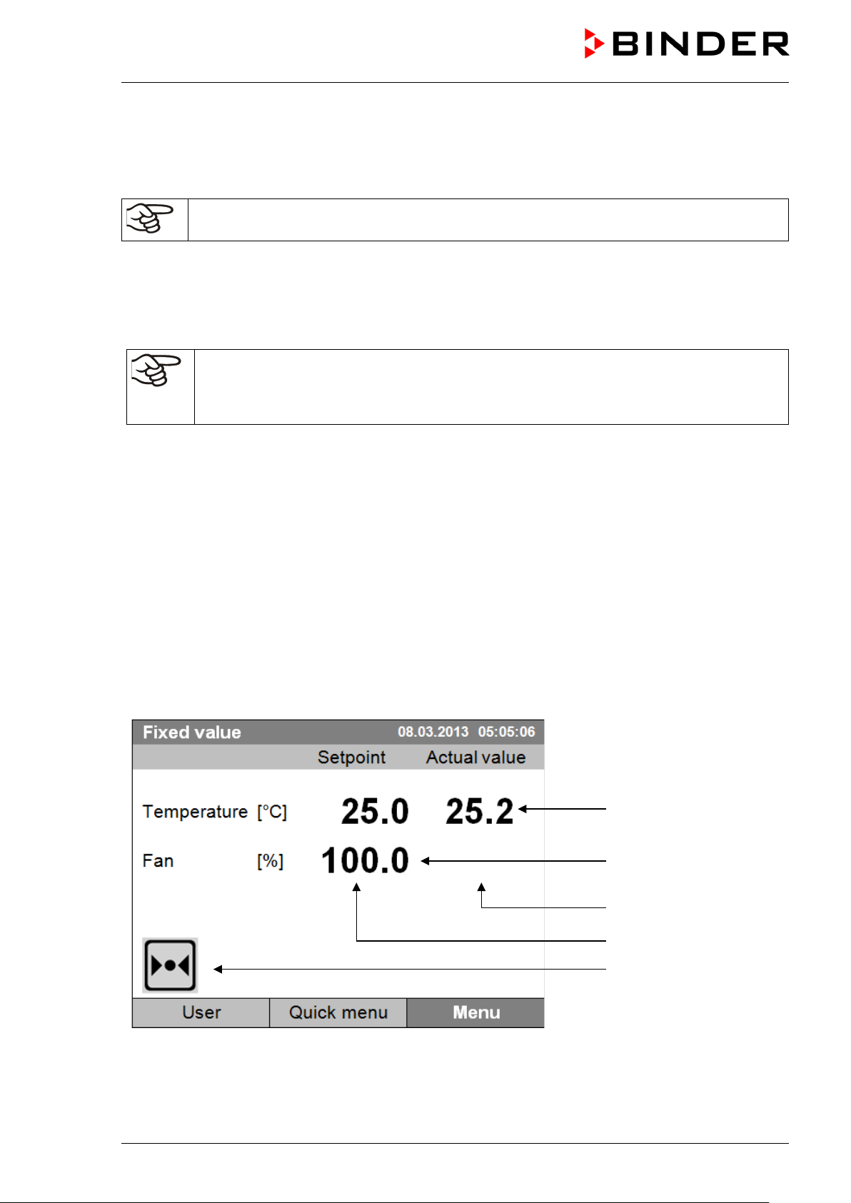
6. Functional overview of the T4.12 chamber controller
The T4.12 chamber controller controls the temperature (range: 4 °C up to 100 °C) and the fan speed (range:
40 % up to 100 %) inside the chamber. You can enter the desired set point values in fixed value operating
mode or in program mode in the display controller. The controller also offers a week program function and
various notifications and alarm messages with visual and audible indication, a trace file and remote alarms
via e-mail. You can enter values or program s directl y at the controller k eypad or using th e APT-COM™ 4
Multi Management Software (option, chap. 19.1) specially developed by BINDER.
Temperature values
Fan speed value
Actual values
Set-point values
Icons:
Controller operating in “fixed
value” operating mode
Figure 8: T4.12 microprocessor controller, initial view in “fixed value” controller mode (sample values)
KT (E6.1) 11/2020 Page 25/139
Page 26
Fixed value
Setpoint
Actual value
25.0
25.2
100.0
Fixed value
..\ Menu
Controller mode
Event list
Alarms
Setpoints
Safety controller
Programs
Import/Export
Settings
Close
Home
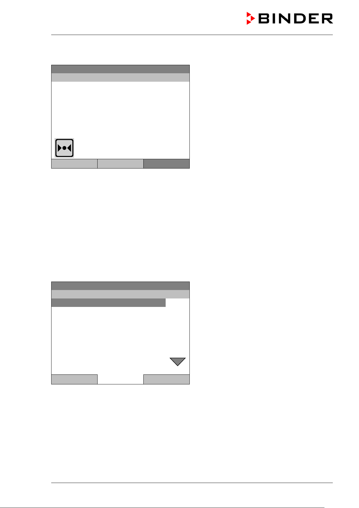
6.1 Menu structure
08.03.2015 05:05:06
Temperature [°C]
Fan [%]
User Quick menu Menu
From the Initial view you ha ve acc es s to dif f erent menus using the menu buttons “User”, “Quick menu” , or
“Menu”. From there you can access the desired control functions. To do this, select the function by turning
the operating button and press the operating button to confirm the selection.
In any menu, you can re turn to the previous disp lay pressing t he "Close" button or to th e initial vie w with
the "Home" button.
Depending on the logged-in user or administrator, the available menu functions may vary. These
instructions present the functions which are available to the logged-in administrator.
Initial view (sample values).
Press the desired menu button.
6.1.1 General menu
The general menu provides access to all setting functions of the controller, a graphical display of the
measured values, and the possibility to read and give out data via the USB interface. In addition, supporting
functions like a settings wizard or a contact page are available.
08.03.2015 05:05:06
General menu
Turn the operating butt on to see additional menu items.
KT (E6.1) 11/2020 Page 26/139
Page 27

Fixed value
..\ Menu
Measurement chart
Optional equipment
Sensor adjustment
Service contact
System information
08.03.2015 05:05:06
General menu (next page)
(“Optional equipm ent” menu item is visible onl y with
optional chamber equipment)
Close Home
Controller mode
Switching between the operating modes “control off” or “fixed value”,
chap. 6.2.1
Event list Display of status information and errors, chap. 15
Alarms Alarm settings, chap. 14.5
Setpoints Setpoint entry in “Fixed value” operating mode, chap. 8
Safety controller Setting the safety controller, chap. 17.2
Programs Time and week programs, chap. 9 and 10
Import/Export Data transfer via USB interface, chap. 13
Settings General controller settings, chap. 12
Measurement chart Graphical display of the measured values, chap. 16
Setting for optional equipment like door heating, interior socket,
Optional equipment
zero-voltage relay control outputs, alarm output, object temperature
display, chap. 7
(menu item is visible only with optional chamber equipment)
Sensor adjustment
Adjustment menu for single-point and two-point adjustments (for
Service purpose)
Service contact Service information
System information Chamber information (model, name, serial no., firmware etc.)
KT (E6.1) 11/2020 Page 27/139
Page 28
Fixed value
..\ Quick menu
Measurement chart
Active alarms
Temperature setpoint
Fan speed setpoint
Safety controller setpoint
Time program
Week program
Close
Home
Fixed value
..\ User
Key lock
Show event list
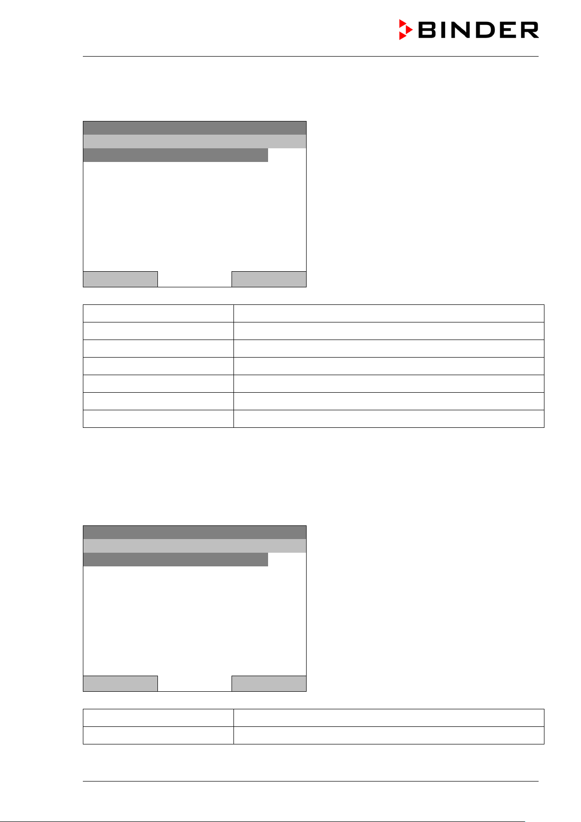
6.1.2 Quick menu
The Quick menu provides fast access to frequently used functions.
08.03.2015 05:05:06
“Quick menu”
Measurement chart
Active alarms
Temperature setpoint
Fan speed setpoint
Safety controller setpoint
Time program
Week program
Graphical display of the measured values, chap. 16
Alarm settings, chap. 14.5
Temperature setpoint entry in “Fixed value” operating mode, chap. 8
Fan speed setpoint entry in “Fixed value” operating mode, chap. 8
Setting the safety controller setpoint, chap. 17.2
Starting and cancelling a time program, chap. 9.1, 9.2
Starting and cancelling a week program, chap. 10.1, 10.2
6.1.3 “User” menu
The user menu includes the key lock function and provides quick access to the event list. The key lock
function serves to block the access to the controller. An overview of logon, logoff, and other events is
given in the event list.
08.03.2015 05:05:06
Key lock Configuring the key lock function, chap. 11
Show event list Displaying the event list, chap. 15
KT (E6.1) 11/2020 Page 28/139
“User” menu
Close Home
Page 29

Fixed value
..\ Menu
Controller mode
Event list
Alarms
Setpoints
Safety controller
Programs
Import/Export
Settings
Fixed value
..\ Controller mode
Control off
Fixed value
6.2 Operating modes
In the “control off” mode (chap. 6.2.1), the controller is non-functional and displays only the actual values.
There is no heating or ref rigeration. The tem perature approxim ates the ambient va lue, the fan turns with
40 % speed.
You can enter the d esired s et point values in “fixed v alue” mode ( chap. 8). T he controller t hen operates
as a fixed-point control, i.e., it reaches and maintains the defined temperature set-point until the next manual
change.
The T4.12 program c ontroller also perm its running a time program (chap. 9) or a week p rogram (chap.
10). You can program temperature cycles and define also the fan sp eed for each program section. The
controller offers 52 time program places with u p to 100 sections e ach. The week progr am mode offer s 8
week program places with up to 30 shift points for each week program.
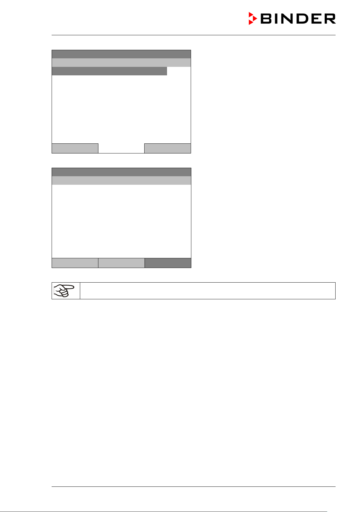
6.2.1 Activating the “control off” mode or change to “fixed value” operating mode
To select the “control off” or “fixed value” operating mode, go to Menu > Controller mode
08.03.2015 05:05:06
Close Home
Close Home
General menu.
Select “Controller Mode”
and press the operating button.
08.03.2015 05:05:06
Submenu “Controller Mode”.
Select the desired controller mode
“Control off” or “Fixed value”
and press the operating button.
KT (E6.1) 11/2020 Page 29/139
Page 30
Control off
..\ Menu
Controller mode
Event list
Alarms
Setpoints
Safety controller
Programs
Import/Export
Settings
Control off
08.03.2015 05:05:06
Actual value
25.2
40.0
Menu
08.03.2015 05:05:06
General menu with controller mode “Control off”.
The controller mode “Fixed value” or “Control off” is
indicated in the display headline.
Close Home
Go back to the initial view with “Home”.
Temperature [°C]
Fan [%]
User Quick menu
The controller is non-functional, i.e., there is no heating or refrigerating. The fan turns at 40 % speed.
In the “Control off” mode, no program can be started.
Initial view in “Control off” mode
(sample picture).
KT (E6.1) 11/2020 Page 30/139
Page 31

Fixed value
..\ System information
Chamber type: KT
Chamber name: KT_E6.1
Serial number: 00-00000
Special application number: 00-0000
Parameter version: 511B-0006-0011
Firmware version (1): 521C-0001-002A
Firmware version (2): 521B-0005-001E
Fixed value
..\ Service contact
Service hotline
International:
+49 7462 2005 555
USA Toll Free:
+ 1 866 885 9794
or
+ 1 631 224 4340
CIS:
+ 7 495 988 1516
service@binder-world.com
www.binder-world.com
6.3 Performance during and after power failure
During a power failure, all controller functions are shut down. The optional zero-voltage relay alarm output
(chap. 19.3) is switched to alarm position for the whole duration of the power failure.
After the power returns, all functions return to the same status the chamber had before power failure. . The
controller continues t o function in the or iginal op eratin g m ode it was in pr evious ly befor e the power failure
occurred.
• Performance after power failure in “fixed value” operation mode
All functions return to the same status the chamber had before power failure. The set-points are
immediately resumed.
• Performance after power failure during time program operation
The program is res umed at the point where th e int er ruptio n oc c urr ed with t he latest set-points reac h ed
during the program run.
• Performance after power failure during week program operation
The week program continues with the values corresponding to the current time.
In the “Control off” controller mode, no program can be started.
If the temperature has dropped below the alarm limit during power failure, confirm the alarm with the RESET
button as soon as the correct values are reached again (chap. 14.4).
6.4 Information
You access chamber information like the chamber type, serial no., firmware version etc. To display the
system information, go to Menu > System information
08.03.2015 05:05:06
Submenu “System information” (sample values).
Close Home
To display the BINDER Service contact data, go to Menu > Service contact
08.03.2015 05:05:06
Close Home
KT (E6.1) 11/2020 Page 31/139
Submenu “Service contact”.
Page 32

Fixed value
..\ Optional equipment
Door heating
Interior socket
Zero-voltage relay control outputs
Functional test – alarm output
Object temperature display
Fixed value
..\ Door heating On/Off
Door heating On/Off
Door heating Offset
Further information windows are accessible under Menu > Settings > Network settings > Show network
settings (chap. 12.9) and – f or service purpose – under Menu > Settings > Chamber configuration
(chap. 12.10).
7. Configuration of optional equipment
The “Optional equipment” menu item is visible only with optional chamber equipment.
To access the selection menu, go to Menu > Optional equipment
08.03.2015 05:05:06
Submenu “Optional equipment”.
Select the desired function
and press the operating button.
Close Home
7.1 Setting the optional door heating
For chambers equipped with an optional door heating, you can turn it on and off via the controller. You can
also set the door heating off s et to the temperature set-point.
To access the door heating setting menu, go to Menu > Optional equipment > Door heating
08.03.2015 05:05:06
Submenu “Door heating”.
Select the desired function
and press the operating button.
“Door heating On/Off” = Turning on or off the door
heating
“Door heating Offset” = Temperature difference to
the entered setpoint
Close Home
KT (E6.1) 11/2020 Page 32/139
Page 33

Fixed value
..\ Door heating On/Off
Door heating: Off
Fixed value
..\ Door heating \ Offset
1
[°C]
Ins Pos1 End Ok
1 2 3 4 5 6 7 8 9 ,
Fixed value
..\ Interior socket
Interior socket: Off
Turning on or off the door heating:
08.03.2015 05:05:06
Submenu “Door heating On/Off ”.
The current setting is indicated.
To change the setting,
press the operating button.
The modified setting is displayed.
“Door heating: On” = door heating turned on
“Door heating: Off” = door heating turned off
Close Home
Setting the offset value:
08.03.2015 05:05:06
Entry menu „Offset“.
Select each number with the operating button and
press the operating button to confirm.
Setting range: 0 °C up to 5 °C.
0
Press the “Ok” button to confirm.
Close Ok Home
Go back to the initial view with “Home”.
This symbol on the controller display indicates that the door heating is active.
7.2 Turning on / off the optional interior socket
For chambers equ ipped with th e water-protected interior soc k et (opt ion, ch ap. 19.7) you can turn o n and
off the voltage of the interior socket via the controller.
To access the setting menu, go to Menu > Optional equipment > Interior socket
08.03.2015 05:05:06
Submenu “Interior socket”.
The current setting is indicated.
To change the setting,
press the operating button.
The modified setting is displayed.
“Interior socket: Off” = socket voltage-free
“Interior socket: On” = socket with activated voltage
KT (E6.1) 11/2020 Page 33/139
Close Home
Page 34

Fixed value
..\ Zero-voltage relay control outputs
Control output 1: Off
Control output 2: Off
Control output 3: Off
Fixed value
..\ Functional test – alarm output
Alarm output: Inactive
Go back to the initial view with “Home”.
This symbol on the controller display indicates that the interior socket is activated.
7.3 Switching on or off the optional zero-voltage relay control outputs
For chambers equipped with zero-voltage relay outputs ( option, chap. 19.5), you can switch on or off the
output via the controller.
To access the setting menu for the operating modes “Fixed value” and “Control off”, go to
Menu > Optional equipment > Zero-voltage relay control outputs.
The setting for program operation is done through the program editor (chap. 9.3.7).
08.03.2015 05:05:06
Submenu “Zero-voltage relay control outputs”.
The current switching state of the zero-voltage relay
control outputs is indicated. To change it, select the
desired control output
and press the operating button.
The modified switching state is displayed.
“Control output: Off” = zero-voltage relay output
deactivated
“Control output: On” = zero-voltage relay output
Close Home
activated
Go back to the initial view with “Home”.
A symbol on the controller display indicates the switching state of the three zero-voltage
relay control outputs, as soon as at least one control output is activated
(example: control outputs 1 + 2 activated)
7.4 Functional test of the optional alarm output
For chambers equipped with the zero-v oltage relay alarm output (option, chap. 19.3), you can switch on
the output for test purpose via the controller and then switch it off again.
To access the setting menu, go to Menu > Optional equipment > Functional test – alarm output
08.03.2015 05:05:06
Submenu “Functional test – alarm output”.
The current switching state is indicated.
To change the switching state,
press the operating button.
The modified switching state is displayed.
“Alarm output: Inactive” = alarm output switched off
“Alarm output: Active” = alarm output switched on
(alarm state)
Close Home
Go back to the initial view with “Home”.
KT (E6.1) 11/2020 Page 34/139
Page 35

Fixed value
..\ Object temperature display
Object temperature display: Off
point remains stored an d becom es effect ive again with tem perature v alues
7.5 Switching on or off the optional object temperature display
For chambers equipped with the digital object temperature display with a flexible Pt 100 temperature sensor
(option, chap. 19.3), you can switch on or off the object temperature indica tio n via the con tr ol ler.
To access the setting menu, go to Menu > Optional equipment > Object temperature display
08.03.2015 05:05:06
Submenu “Object temperature display”.
The current setting is indicated.
To change the setting,
press the operating button.
The modified setting is displayed.
“Object temperature display: Off” = Object
temperature display deactivated
„Object temperature display: On“ = Object
temperature display activated
Close Home
Go back to the initial view with “Home”.
8. Set-point entry in “Fixed value” operating mode
8.1 Setting ranges:
Temperature 4 °C / 23 °F up to +100 °C / 212 °F
Fan speed 40 % up to 100 % (full speed) with temperature values from 4 °C up to 70 °C
With temperature values above 70 °C the effective fan speed is always 100 %. The fan
speed set< 70 °C.
Reduce the fan speed only if required, because the spatial distribution of temperature
will also be reduced.
Technical data refers to 100% fan speed.
When you changed the temperature set-point, check the setting of the overtemperature
safety controller class 3.1 (chap. 17.2) or the over-/undertemperature safety controller class
3.3 (option, chap. 17.3).
With set-point type “Limit”, adapt the safety controller always when changing the temper ature
set-point.
KT (E6.1) 11/2020 Page 35/139
Page 36

Fixed value
..\ Quick menu
Measurement chart
Active alarms
Temperature setpoint
Fan speed setpoint
Safety controller setpoint
Time program
Week program
When trying to enter a setpoint in the „Contro ller off“ operating mode, a notification window
2
[°C]
8.2 Enter ing the set-points via “quick menu”
To enter set-points via quick menu, go to Quick menu.
08.03.2015 05:05:06
“Quick menu”.
Select the desired parameter
and press the operating button.
Close Home
shows “Controller mode is OFF!”. Pr ess the o per at ing butto n to confirm with “Ok ” and c hange
the operating mode to “Fixed value” (chap.
6.2.1).
Temperature setting
To enter the temperature setpoint, go to Quick menu > Temperature setpoint
Fixed value
08.03.2015 05:05:06
..\ Temperature setpoint
Entry menu “Temperature setpoint”.
End Ok 0 1
3 4 5 6 7 8 9 . -
2
Select each number with the operating button and
press the operating button to confirm.
Setting range: 4 °C / 23 °F up to +100 °C / 212 °F
Press the “Ok” button to confirm.
Close Ok Home
When entering a value outside the setting range, the message “invalid value” appears. Press the operating
button to confirm with “Ok” and repeat the entry with a correct value.
Go back to the initial view with “Home” or enter the fan speed.
KT (E6.1) 11/2020 Page 36/139
Page 37

Fixed value
(effective with temperature values from 4 °C to 70 °C.
..\ Fan speed setpoint
1
[%]
Fixed value
..\ Setpoints
Temperature
Fan speed
Fan speed setting
To enter the fan speed setpoint, go to Quick menu > Fan speed setpoint
08.03.2015 05:05:06
Entry menu “Fan speed setpoint”.
Select each number with the operating button and
press the operating button to confirm.
Setting range: 40 % up to 100 %
Pos1 End Ok 0
2 3 4 5 6 7 8 9 , -
1
With temperature values > 70 °C always 100 %)
Press the “Ok” button to confirm.
Close Ok Home
When entering a value outside the setting range, the message “invalid value” appears. Press the operating
button to confirm with “Ok” and repeat the entry with a correct value.
Go back to the initial view with “Home”.
When operating the fan with less than 100 % speed, the temperature performance and the
spatial exactitude of the temperature may differ from the manufacturer’s specifications. Do
reduce the fan speed only if absolutely necessary due to special requirements.
8.3 Enter ing the set-points via general menu
To enter set-points via general menu, go to Menu > Setpoints
08.03.2015 05:05:06
Submenu “Setpoints”.
Select “Temperature” or “Fan speed”
and press the operating button.
Close Home
KT (E6.1) 11/2020 Page 37/139
Page 38

Fixed value
..\ Temperature setpoint
2
[°C]
Fixed value
..\ Fan speed setpoint
1
[%]
Temperature setting
To enter the temperature setpoint, go to Menu > Setpoints > Temperature
08.03.2015 05:05:06
Entry menu “Temperature setpoint”.
Pos1 End Ok 0 1
3 4 5 6 7 8 9 , -
2
Select each number with the operating button and
press the operating button to confirm.
Setting range: 4 °C / 23 °F up to +100 °C / 212 °F
Press the “Ok” button to confirm.
Close Ok Home
When entering a value outside the setting range, the message “Invalid value” a ppear s. Press the operating
button to confirm with “Ok” and repeat the entry with a correct value.
Go back to the initial view with “Home” or enter the fan speed.
Fan speed setting
To enter the fan speed setpoint, go to Menu > Setpoints > Fan speed
08.03.2015 05:05:06
Pos1 End Ok 0
2 3 4 5 6 7 8 9 . -
1
Entry menu “Fan speed setpoint”.
Select each number with the operating button and
press the operating button to confirm.
Setting range: 40 % up to 100 %
(effective with temperature values from 4 °C to
70 °C. With temperature values > 70 °C always
100 %)
Press the “Ok” button to confirm.
Close Ok Home
When entering a value outside the setting range, the message “invalid value” appears. Press the operating
button to confirm with “Ok” and repeat the entry with a correct value.
Go back to the initial view with “Home”.
KT (E6.1) 11/2020 Page 38/139
When operating the fan with less than 100 % speed, the temperature performance and the
spatial exactitude of the temperature may differ from the manufacturer’s specifications. Do
reduce the fan speed only if absolutely necessary due to special requirements.
Page 39

Fixed value
Setpoint
Actual value
25.0
25.2
100.0
Fixed value
..\ Menu
Controller mode
Event list
Alarms
Setpoints
Safety controller
Programs
Import/Export
Settings
Fixed value
..\ Programs
Time program
Week program
9. Time programs
The T4.12 program controller permits programming temperature cycles. It offers 52 program memory
positions with up to 100 program sections each.
To access the menu selection for time programs, select Menu > Programs > Time program
08.03.2015 05:05:06
Temperature [°C]
Fan [%]
User Quick menu Menu
Close Home
Initial view.
Press the “Menu” button.
08.03.2015 05:05:06
General menu.
Select “Programs”
and press the operating button
08.03.2015 05:05:06
Submenu “Programs”.
Select “Time Program”
and press the operating button
Close Home
KT (E6.1) 11/2020 Page 39/139
Page 40

Fixed value
..\ Programs\Time programs
Start
Stop
Pause
Resume
Edit
Create
Rename
Delete
Fixed value
..\ Programs\Time programs
Delete all
Fixed value
..\ Programs\Time programs
Start
Stop
Pause
Resume
Edit
Create
Rename
Delete
08.03.2015 05:05:06
Submenu “Time programs”.
Turn the operating button to see additional menu
items.
Close Home
08.03.2015 05:05:06
Submenu “Time programs” (next page)
Close Home
9.1 Star ti ng and running an existing time program
To start a time program, go to Menu > Programs > Time program > Start.
(You can also go to Quick menu > Time program > Start , see below).
Starting is also possible directly from the program editor (chap. 9.3.9).
In the “Control off” mode or during a running time or week program, no time program can be
started.
08.03.2015 05:05:06
Close Home
If no program has been c reated an d save d so f ar, the mess age “No progr ams f ound” appe ars. Pr ess the
operating button to confirm with “Ok” and enter a program with “Create”.
KT (E6.1) 11/2020 Page 40/139
Submenu “Time program”.
Select “Start” to start an existing program
and press the operating button.
Page 41

Fixed value
..\ Select program
Program0001
Program0002
Program0003
Fixed value
..\ Start date (DD.MM.YYYY)
0
8.03.2015
3 4 5 6 7 8 9
0
08.03.2015 05:05:06
Submenu “Select program” (example).
Select one of the programs
and press the operating button to run the program
Close Home
08.03.2015 05:05:06
Entry menu “Start date”.
Ins Pos1 End Ok 1 2
0
The current date is shown. For a postponed start,
enter the desired start date with the operating
button.
Press the “Ok” button to confirm.
Close Ok Home
Fixed value
08.03.2015 05:05:06
..\ Start time (HH:MM:SS)
Ins Pos1 End 1 2 3 4 5 6 7 8 9
0
Close Ok Home
Entry menu “Start time”.
The current time plus 30 seconds is shown. For a
postponed start, enter the desired start time with the
operating button.
Press the “Ok” button to confirm.
KT (E6.1) 11/2020 Page 41/139
Page 42

Time program
08.03.2015 05:05:06
Program0001
10.0
11.5
Section 20 End: 08.03.2015 08:07:44
100.0
Fixed value
..\ Quick menu
Measurement chart
Active Alarms
Temperature setpoint
Fan speed setpoint
Safety controller setpoint
Time program
Week program
Fixed value
..\ Time program
Start
Stop
Setpoint Actual value
Temperature [°C]
Initial view (example values).
Fan [%]
User Quick menu Menu
This symbol on the controller display indicates that a time program is running.
During a running time program, it is impossible to edit, rename or delete this program (when selecting such
a function, a corresponding message is displayed). The other program functions are available.
The time program is running.
During a running time program, no week program can be started.
To start a time program, you can also go to Quick menu > Time program > Start
08.03.2015 05:05:06
“Quick menu”.
Select “Time program”
and press the operating button
Close Home
08.03.2015 05:05:06
Submenu “Time program”.
Select “Start” to start an existing program
and press the operating button.
Close Home
The further procedure is equal to that described for the general menu.
KT (E6.1) 11/2020 Page 42/139
Page 43

Fixed value
..\ Select program
Program0001
Program0002
Program0003
NOTICE
08.03.2015 05:05:06
Submenu “Select program” (example).
Select one of the programs
and press the operating button to start the program
Close Home
Performance after completing the program
The controller automatically changes to the “Fixed value” operation mode.
Before starting the program , c heck the tem peratur e setpoi nt ent ered i n the “ Fixe d value” opera tion m ode.
After end of the program, the temperature will equilibrate to this value.
NOTICE
Danger of too high or too low temperature after the program ends.
Damage to the charging material.
Before starting the program, check the temperature setpoint of “Fixed value” operation
and if necessary adapt it.
9.2 Cancelling a running time program
To cancel a running time program, go to Menu > Programs > Time program > Stop.
To cancel a running time program, you can also go to Quick menu > Time program > Stop.
The controller returns to the initial view.
Performance after manual program stop
The controller automatically changes to the “Fixed value” operation mode.
Before starting a pro gram, check the tem perature setpoint entere d in the “Fixed value” operation mode.
After cancelling the program, the temperature will equilibrate to this value.
Danger of too high or too low temperature after cancelling the program.
Damage to the charging material.
Before starting the program, check the temperature setpoint of “Fixed value” operation
and if necessary adapt it.
KT (E6.1) 11/2020 Page 43/139
Page 44

Fixed value
..\ Programs\Time programs
Start
Stop
Pause
Resume
Edit
Create
Rename
Delete
Fixed value
..\ Create new program
New
Based on…
9.3 Creating a new time program
For each program section you can enter a temperature set-point, the fan speed, the section’s duration, the
type of temperature transition “R” (ramp) or “S” (step) (see chap. 9.3.6), and the tolerance range.
When changing the temperature set-point, check the setting of the safety controller (chap. 17)
if the safety controller has been set to “limit” mode.
If the fan is operated with less than 100 % speed, the temperature performance and the
spatial exactitude of the temperature can differ from the manufacturer’s specifications. The
fan speed rate should only be reduced if absolutely necessary to meet special requirements.
Programming is saved in case of a power failure or after turning off the chamber.
To enter a new time program, go to Menu > Programs > Time programs > Create
08.03.2015 05:05:06
Close Home
Creating a new program
Submenu “Time program”.
Select “Create"
and press the operating button.
08.03.2015 05:05:06
Submenu “Create new program”.
Select “New", to create an entirely new program, or
“Based on…”, to use an existing program for further
editing
and press the operating button.
Close Home
KT (E6.1) 11/2020 Page 44/139
Page 45

Fixed value
..\ Select program
Program0001
Program0002
Program0003
Enter name
Fixed value
..\ Temperature controller
No.
Value
H:M:S
Ref.
Rep.
T. min
T.max
R/S
1
25.00
00:00:15
1 0 -999.00
999.00
Ramp
If you selected “Based on”, then the program selection window appears:
08.03.2015 05:05:06
Submenu “Select program” (example).
Select the desired program
and press the operating button.
Close Home
If no program has been c reated an d save d so f ar, the message “ No program s f ound” appe ars. Pres s the
operating button to confirm with “Ok” and enter a program with “Create”.
Now you can specify the name of the new time program:
08.03.2015 05:05:06
..\ Program
T U V W X Y Z 1 2 3 4 5 6 7 8 9
0
Entry menu “Program”.
Enter the desired start time with the operating
button.
Press the “Ok” button to confirm.
Close Ok Home
The time program editor is displayed. Following the selection “Based on …”, this table for program entry
shows the values of the selected program. F ollowing the selection “New" ther e is an empty table, which
can be filled section by section with sample values. You can edit the displayed values.
Entering the program values for the first parameter (temperature)
A first program line is shown. This corresponds to a program section. You can now edit the values.
08.03.2015 05:05:06
KT (E6.1) 11/2020 Page 45/139
Time program editor
(view with optional control outputs).
To edit the values, press the operating button, select
the desired value and press the operating button
again.
Menu
Page 46

Fixed value
..\ Temperature controller
No.
Value
H:M:S
Ref.
Rep.
T. min
T.max
R/S
1
25.00
00:00:15
1 0 -999.00
999.00
Ramp
2
25.00
00:00:15
1 0 -999.00
999.00
Ramp
3
25.00
00:00:15
1 0 -999.00
999.00
Ramp
Fixed value
..\ Temperature controller
No.
Value
H:M:S
Ref.
Rep.
T. min
T.max
R/S
1
25.00
00:00:15
1 0 -999.00
999.00
Ramp
Fixed value
..\ Program sections
Insert
Copy
Paste
Delete
To create a second pro gram line (section), turn the o perating button to the right and pres s it. The next
section will be added.
08.03.2015 05:05:06
Time program editor
(view with optional control outputs).
To edit the values, press the operating button, select
the desired value and press the operating button
again.
Menu
The right column for the 3 control outputs is visible only on chambers equipped with optional control outputs.
9.3.1 Section handling
08.03.2015 05:05:06
08.03.2015 05:05:06
Close
Note: When selecting „Insert“ or “Paste”, the new program section is inserted before the current section.
Time program editor.
Select a value under “No.”
and press the operating button.
Submenu “Program sections“.
Select the desired function
and press the operating button.
KT (E6.1) 11/2020 Page 46/139
Page 47

Fixed value
..\ Temperature controller
[°C]
No.
Value
H:M:S
Ref.
Rep.
T. min
T.max
R/S
1
25.00
00:00:15
1 0 -999.00
999.00
Ramp
2
[°C]
Fixed value
..\ Temperature controller
[°C]
No.
Value
H:M:S
Ref.
Rep.
T. min
T.max
R/S
1
25.00
00:00:15
1 0 -999.00
999.00
Ramp
Fixed value
..\ Section duration
0
0:00:15
9.3.2 Temperature setpoint
08.03.2015 05:05:06
Time program editor.
Select a value under “Value”
and press the operating button.
Fixed value
08.03.2015 05:05:06
..\ Temperature setpoint
Entry menu “Temperature setpoint”.
Pos1 End Ok 0 1
3 4 5 6 7 8 9 , -
2
A temperature value is shown. Enter the desired
value with the operating button.
Setting range: 4 °C up to 100 °C.
Press the “Ok” button to confirm.
Close Ok
When entering a value outside the setting range, the message “invalid value” appears. Press the operating
button to confirm with “Ok” and repeat the entry with a correct value.
9.3.3 Section duration
08.03.2015 05:05:06
08.03.2015 05:05:06
Ins Pos1 End Ok 1 2 3 4 5 6 7 8 9
0
Close Ok
Time program editor.
Select a value under “H:M:S”
and press the operating button.
Entry menu “Section duration”.
A duration value is shown. Enter the desired val ue
with the operating button.
Press the “Ok” button to confirm.
KT (E6.1) 11/2020 Page 47/139
Page 48

Fixed value
..\ Temperature controller
[°C]
No.
Value
H:M:S
Ref.
Rep.
T. min
T.max
R/S
1
25.00
00:00:15
1 0 -999.00
999.00
Ramp
Fixed value
..\ Reference section
1
Pos1 End Ok 0
2 3 4 5 6 7 8 9 ,
Close
Ok
Fixed value
..\ Temperature controller
[°C]
No.
Value
H:M:S
Ref.
Rep.
T. min
T.max
R/S
1
25.00
00:00:15
1 0 -999.00
999.00
Ramp
0
9.3.4 Repeating one or several sections within a time program
Enter the number of the ta rget section, which shal l be the start of the repeat c ycle, under “Ref.” and the
number of repeats under “Rep.”. To have sections repeated infinitely enter the number of cycles “Rep.” as
“-1”.
08.03.2015 05:05:06
08.03.2015 05:05:06
1
Continue to enter the number of repeats:
Time program editor.
Select a value under “Ref.”
and press the operating button.
Entry menu “Reference section”.
Enter the target section number of the repeat cycle
with the operating button.
Press the “Ok” button to confirm.
Fixed value
..\ Number of repeats
Del Pos1 End Ok
1 2 3 4 5 6 7 8 9
0
Close Ok
08.03.2015 05:05:06
08.03.2015 05:05:06
Time program editor.
Select a value under “Rep.”
and press the operating button.
Entry menu “Number of repeats”.
Enter the desired number of repeats with the
operating button.
Press the “Ok” button to confirm.
KT (E6.1) 11/2020 Page 48/139
Page 49

Fixed value
..\ Temperature controller
[°C]
No.
Value
H:M:S
Ref.
Rep.
T. min
T.max
R/S
1
40.00
00:30:00
1 0 -999.00
999.00
Ramp
2
60.00
01:30:00
1 0 -999.00
999.00
Ramp
3
80.00
01:00:00
2
30
-999.00
999.00
Ramp
4
20.00
03:20:00
1 0 -999.00
999.00
Ramp
Fixed value
..\ Temperature controller
[°C]
No.
Value
H:M:S
Ref.
Rep.
T. min
T.max
R/S
1
25.00
00:00:15
1 0 -999.00
999.00
Ramp
Fixed value
..\ Tolerance range minimum temperature
-
999.00
[°C]
Close
Ok
The following example shows a time program where the sections 2 and 3 shall be repeated 30 times:
08.03.2015 05:05:06
Time program editor.
Menu
Sections 2 and 3 will be executed in total 31 times; only then will the program continue.
9.3.5 Tolerance range
You can specify a tolerance range for each program section with different values for the tolerance minimum
and maximum. When t he actual value exceeds the gi ven threshold, the program is interrupted. This is
indicated on the dis pla y, see chap. 9.4. When the actual tem peratur e is situ ated agai n within the entered
tolerance limits, the program automatically continues. Therefore, the duration of the program may be
extended due to the programming of tolerances.
Programming of tolerances may extend program duration.
An entry of “-999” for the tolerance minimum means “minus infinite” and an entry of “999” for the tolerance
maximum means “plus infinite”. Entry of these values will never lead to program interruption.
When requesting a rapid temperature transition, we recommend not programming tolerance values in order
to enable the maximum heating-up or cooling-down speed.
Start with the minimum value:
08.03.2015 05:05:06
Time program editor.
Select a value under “T. min”
and press the operating button.
08.03.2015 05:05:06
2 3 4 5 6 7 8 9 , Del Ins Pos1
-
Entry menu “Tolerance range minimum
temperature”.
Enter the desired value with the operating button.
Press the “Ok” button to confirm.
KT (E6.1) 11/2020 Page 49/139
Page 50

Fixed value
..\ Temperature controller
[°C]
No.
Value
H:M:S
Ref.
Rep.
T. min
T.max
R/S
1
25.00
00:00:15
1 0 -999.00
999.00
Ramp
9
99.00
[°C]
Continue to enter the maximum value:
08.03.2015 05:05:06
Fixed value
08.03.2015 05:05:06
..\ Tolerance range maximum temperature
0 1 2 3 4 5 6 7 8 , - Del Ins Pos1
9
Close Ok
Time program editor.
Select a value under “T. max”
and press the operating button.
Entry menu “Tolerance range maximum
temperature”.
Enter the desired value with the operating button.
Press the “Ok” button to confirm.
9.3.6 Set-point ramp and set-point step modes
“Ramp” mode
The set-point of a given program section functions as the section’s target temperature. During the section’s
duration, the tem peratur e set-point gradual ly passes from the set-point of th e previous program sec tion to
this target set-point. The actual temperature value follows the continually changing set-point.
Programming in the “ramp” mode allows various kinds of temperature transitions:
• Gradual slow temperature changes
The set-point changes its value gradual ly during the entered section duration. T he actual t em perature
value (X) follows the continually moving set-point (W) at any time.
• Constant temperature
The initial values of two subsequent program sections are identical; so the temperature remains constant
during the duration of the first program section.
• Sudden temper atur e changes
These changes occur rapidly within the minimum amount of time (minimum entry: 1 second).
“Step” mode
The set-point of a given program sec tion functions as the sec tion’s target tem perature. At the s tart of the
program section, the chamber heats up or cools down with the maximum speed to reach the entered value;
and then it holds it for the remaining section tim e. The set-point temperature r emains constant for the
section’s duration.
KT (E6.1) 11/2020 Page 50/139
Page 51

Fixed value
..\ Temperature controller
[°C]
No.
Value
H:M:S
Ref.
Rep.
T. min
T.max
R/S
1
25.00
00:00:15
1 0 -999.00
999.00
Ramp
Fixed value
..\ Ramp/step
Ramp
Step
W/°C
t/min.
01
02
03
04
0
20
40
60
80
100
30
120
180
330
05
24
0
No.
Value
H:M:S
Ref.
Rep.
T. min
T.max
R/S
01
40.0
00:30:00
1 0 -999
+999
Ramp
02
60.0
01:30:00
1 0 -5
+5
Ramp
03
60.0
01:00:00
1 0 -2
+2
Ramp
04
80.0
01:00:00
1 0 -999
+999
Ramp
05
40.0
01:30:00
1 0 -999
+999
Ramp
Selecting the setting “Ramp” or “Step”:
Close
Examples:
08.03.2015 05:05:06
08.03.2015 05:05:06
Time program editor.
Select a value under “R/S”
and press the operating button.
Submenu “Ramp/step“.
Select the desired function
and press the operating button.
“Ramp” = Setpoint ramp mode selected
“Step” = Setpoint step mode selected
“Ramp” mode
Corresponding program table:
KT (E6.1) 11/2020 Page 51/139
Page 52

W/°C
t/min.
01 02 03 04
0
20
40
60
80
100
30
120
180
380
No.
Value
H:M:S
Ref.
Rep.
T. min
T.max
R/S
01
40.0
00:30:00
1 0 -999
+999
Step
02
60.0
01:30:00
1 0 -5
+5
Step
03
80.0
01:00:00
1 0 -2
+2
Step
04
20.0
03:20:00
1 0 -999
+999
Step
Fixed value
..\ Temperature controller
[°C]
No.
Value
H:M:S
Ref.
Rep.
T. min
T.max
R/S
1
25.00
00:00:15
1 0 -999.00
999.00
Rampe
Fixed value
..\ Zero -voltage relay outputs
Outputs 1 [Off] 2[Off] 3[Off]
Outputs 1[On] 2[Off] 3[Off]
Outputs 1[Off] 2[On] 3[Off]
Outputs 1[Off] 2[Off] 3[On]
Outputs 1[On] 2[Off] 3[On]
Outputs 1[Off] 2[On] 3[On]
Outputs 1[On] 2[On] 3[On]
A symbol on the controller display indicates the switching state of the three zero-voltage
on)
“Step” mode
Corresponding program table:
9.3.7 Switching on or off the optional zero-voltage relay outputs
For chambers equipped with zero-voltage rela y outputs (option, chap. 19.5), you can switch on or off the
outputs for each program section via the program editor.
08.03.2015 05:05:06
08.03.2015 05:05:06
Time program editor (with option relay outputs)
Select a field under “ ”
and press the operating button.
Submenu “Zero -voltage relay outputs”.
The possible combination of switching states are
indicated.
Select the desired combination of switching states
and press the operating button.“
[On] = zero-voltage relay outputs turned on
[Off] = zero-voltage relay outputs turned off
Close
relay outputs as soon as at least one output is switched on (example: outputs 1 + 2 turned
KT (E6.1) 11/2020 Page 52/139
Page 53

Fixed value
..\ Temperature controller
[°C]
No.
Value
H:M:S
Ref.
Rep.
T. min
T.max
R/S
1
40.00
00:30:00
1 0 -999.00
999.00
Step
2
60.00
01:30:00
1 0 -5.00
5.00
Step
3
80.00
01:00:00
1 0 -5.00
5.00
Step
4
20.00
03:20:00
1 0 -999.00
999.00
Step
5
40.00
00:30:00
1 0 -999.00
999.00
Step
6
60.00
01:30:00
1 0 -5.00
5.00
Step
7
70.00
01:00:00
1 0 -5.00
5.00
Step
8
60.00
01:00:00
1 0 -5.00
5.00
Step
Fixed value
..\ Program menu
Select parameter
Save and exit
Save and run
Exit (without saving!)
Fixed value
..\ Program parameters
Temperature controller
Fan speed
Close
9.3.8 Calling up the next parameter
08.03.2015 05:05:06
Time program editor (example).
Press the “Menu” button.
Menu
08.03.2015 05:05:06
Close
With the “Close” button, the controller returns to the time program editor.
Submenu “Program menu”.
Select “Select parameter”
and press the operating button.
08.03.2015 05:05:06
Submenu “Program parameters”.
Select “Fan speed main controller”
and press the operating button.
KT (E6.1) 11/2020 Page 53/139
Page 54

Fixed value
..\ Fan speed
[%]
No.
Value
H:M:S
Ref.
Rep.
T. min
T.max
R/S
1
100.00
00:30:00
1 0 ***
***
Ramp
1
100.00
00:10:00
1 0 ***
***
Ramp
1
100.00
00:30:00
2 3 ***
***
Ramp
1
100.00
01:00:00
1 0 ***
***
Ramp
Fixed value
..\ Fan speed
[%]
No.
Value
H:M:S
Ref.
Rep.
T. min
T.max
R/S
1
100.00
00:00:15
1 0 ***
***
Ramp
Fixed value
..\ Fan speed setpoint
1
[%]
Entering the set-point values for another parameter (fan speed)
The number of program lines (program sections) equal to the number in the temperature program is
displayed. T he settings of section length, re peats and the selection „Ram p“ or „ Step“ are tak en over from
the temperature pro gram; they ar e no editabl e in this vi ew. The symbol “ *** ” indicates that there ar e no
tolerance value required for the fan speed. You can enter the fan speed set-points.
If you want to insert further sections or perform any other programming, first change back to
the temperature program through Menu > Select parameter > Temperature controller.
08.03.2015 05:05:06
Time program editor (example).
To edit the values, press the operating button, select
the desired value and press the operating button
again.
Menu
Entering the fan speed setpoint
Pos1 End Ok 0
2 3 4 5 6 7 8 9 ,
1
08.03.2015 05:05:06
08.03.2015 05:05:06
Time program editor.
Select a value under “Value”
and press the operating button.
Entry menu “Fan speed setpoint”.
A fan speed value is shown. Enter the desired value
with the operating button.
Setting range: 40 % up to 100 %
Press the “Ok” button to confirm.
When entering a value outside the setting range, the message “invalid value” appears. Press the operating
button to confirm with “Ok” and repeat the entry with a correct value.
KT (E6.1) 11/2020 Page 54/139
Close Ok
Page 55

Fixed value
..\ Temperature controller
[°C]
No.
Value
H:M:S
Ref.
Rep.
T. min
T.max
R/S
1
40.00
00:30:00
1 0 -999.00
999.00
Step
2
60.00
01:30:00
1 0 -5.00
5.00
Step
3
80.00
01:00:00
1 0 -5.00
5.00
Step
4
20.00
03:20:00
1 0 -999.00
999.00
Step
5
40.00
00:30:00
1 0 -999.00
999.00
Step
6
60.00
01:30:00
1 0 -5.00
5.00
Step
7
70.00
01:00:00
1 0 -5.00
5.00
Step
8
60.00
01:00:00
1 0 -5.00
5.00
Step
Fixed value
..\ Program menu
Select parameter
Save and exit
Save and run
Exit (without saving!)
9.3.9 Saving the time program and leaving the program editor
08.03.2015 05:05:06
Time program editor (example).
Press the “Menu” button.
Menu
08.03.2015 05:05:06
Submenu “Program menu”.
Select “Save and exit”
and press the operating button.
Close
With the „Close“ button, the controller returns to the time program editor.
Select parameter Changing between temperature and fan speed.
Saving the program. The controller returns to the “Time programs”
Save and exit
submenu. You can now select and start the program as described
in chap. 9.1.
Saving the program and start it. Enter the start date and time, see
Save and run
chap. 9.1. If another time or week program is running, the program
is only saved, but not st arted. A corresponding message is
displayed.
Exit (without saving!)
Attention: the pr ogram is not saved. After a security question, the
controller returns to the initial view.
Button “Close”
KT (E6.1) 11/2020 Page 55/139
The controller returns to the time program editor. You can continue
programming.
Make sure that you saved the time program before leaving the program editor.
Page 56

Fixed value
..\ Confirm operation
Do not exit
Really exit (without saving!)
Close
Time program
..\ Time program
Start
Stop
Pause
Resume
Edit
Create
Rename
Delete
Time program paused
Program0001
Setpoint
Actual value
10.0
11.5
Section 02 End: 08.03.2015 08:07:44
100.0
Menu
With “Exit (without saving!)” you ex it the program editor without saving the pr ogram. There is a s ecurity
question first:
08.03.2015 05:05:06
Submenu “Confirm operation”.
This a security question. Select the desired function
and press the operating button.
If you selected “Really exit (without saving!)”, the controller goes back to the initial view.
9.4 Progr am interruption
You can manually inter rupt a time program (pause), or this will automatically occur when exceed ing the
entered tolerance range values of the corresponding program section (see chap. 9.3.5).
Manual program interruption
To interrupt a time program, go to Menu > Programs > Time programs > Pause
08.03.2015 05:05:06
Submenu “Time program”.
Select “Pause” to interrupt the running time program
and press the operating button.
Close Home
With button “Home” the controller returns to the initial view.
08.03.2015 05:05:06
Temperature [°C]
Fan [%]
User Quick menu
KT (E6.1) 11/2020 Page 56/139
Initial view (example values).
The time program is running, but halted. The final
time (in this example: 08:07:44) is running.
Page 57

Time program paused
..\ Time program
Start
Stop
Pause
Resume
Edit
Create
Rename
Delete
Close
Home
Fixed value
..\ Programs\Time program
Start
Stop
Pause
Resume
Edit
Create
Rename
Delete
This symbol on the controller display indicates that a running time program is interrupted.
Continuing the time program after a manual interruption
08.03.2015 05:05:06
Submenu “Time program”.
Select “Resume” to continue the time program
and press the operating button.
With button “Home” the controller returns to the initial view.
9.5 Deleting a time program
To delete a time program, go to Menu > Programs > Time program > Delete or
Menu > Programs > Time program > Delete all
08.03.2015 05:05:06
Submenu “Time program”.
Select “Delete” or “Delete all” (next page)
and press the operating button
Close Home
If you selected “Delete”, select then the time program to be deleted and press the operating button.
If you selected “Delete all”, all time programs will be deleted in the controller.
KT (E6.1) 11/2020 Page 57/139
Page 58

Fixed value
..\ Confirm operation
Do not delete
Really delete
Fixed value
08.03.2015 05:05:06
Setpoint
Actual value
25.0
25.2
100.0
Menu
Fixed value
..\ Menu
Controller mode
Event list
Alarms
Setpoints
Safety controller
Programs
Import/Export
Settings
Before deleting there is a security question:
08.03.2015 05:05:06
Submenu “Confirm operation”.
This a security question. Select the desired function
and press the operating button.
Close Home
Go back to the init i al vi e w wit h “Home”.
10. Week programs
The T4.12 program controller permits programming week programs with real-time reference. It of fers 8
week program places in total with up to 30 shift points for each week program.
To access the menu selection for week programs, select Menu > Programs > Week program
Temperature [°C]
Fan [%]
User Quick menu
08.03.2015 05:05:06
Initial view.
Press the “Menu” button.
KT (E6.1) 11/2020 Page 58/139
General menu.
Select “Programs”
and press the operating button
Close Home
Page 59

Fixed value
..\ Programs
Time program
Week program
Fixed value
..\ Programs\Week program
Start
Stop
Edit
Create
Rename
Delete
Delete all
Fixed value
..\ Select program
Program0004
Program0005
Day-Night
08.03.2015 05:05:06
Submenu “Programs”.
Select “Week Program”
and press the operating button
Close Home
10.1 S tarting and running an existing week program
To start a week program, go to Menu > Programs > Week program > Start
(You can also go to Qu i ck men u > Week prog ram > Start , see below).
Starting is also possible directly from the program editor (chap. 10.3.8).
In the “Control off” mode or during a running time or week program, no week program can be
started.
08.03.2015 05:05:06
Submenu “Week program”.
Select “Start” to start an existing week program
and press the operating button
Close Home
08.03.2015 05:05:06
Close Home
KT (E6.1) 11/2020 Page 59/139
Submenu “Select program” (example).
Select one of the programs
and press the operating button to run the program
Page 60

Fixed value
..\ Start date (DD.MM.YYYY)
0
8.03.2015
0
Week program
08.03.2015 05:05:06
Program0004
Setpoint
Actual value
15.0
15.3
Section: 0002 End: Sunday 00:00:00
100.0
If no program has been c reated an d save d so f ar, the message “No program s found” a ppears . Press the
operating button to confirm with “Ok” and enter a program with “Create”.
08.03.2015 05:05:06
Entry menu “Start date”.
End Ok 0 1 2 3 5 6 7 8 9 , - Del
4
The current date is shown. For a postponed start,
enter the desired start date with the operating
button.
Press the “Ok” button to confirm.
Close Ok Home
Fixed value
08.03.2015 05:05:06
..\ Start time (HH:MM:SS)
Entry menu “Start time”.
Ins Pos1 End 1 2 3 4 5 6 7 8 9
0
The current time plus 30 seconds is shown. For a
postponed start, enter the desired start time with the
operating button.
Press the “Ok” button to confirm.
Close Ok Home
Temperature [°C]
Initial view.
Fan [%]
The week program is running.
User Quick menu Menu
This symbol on the controller display indicates that a week program is running.
During a running week program, it is impossible to e dit, rename or delete this program (when selecting
such a function, a corresponding message is displayed). The other program functions are available.
During a running week program, no time program can be started.
KT (E6.1) 11/2020 Page 60/139
Page 61

Fixed value
..\ Quick menu
Measurement chart
Active Alarms
Temperature setpoint
Fan speed setpoint
Safety controller setpoint
Time program
Week program
Fixed value
..\ Week program
Start
Stop
Fixed value
..\ Select program
Program0001
Program0002
Program0003
To start a week program, you can also go to Quick menu > Week program > Start
08.03.2015 05:05:06
“Quick menu”.
Select “Week program”
and press the operating button
Close Home
08.03.2015 05:05:06
Submenu “Week program”.
Select “Start” to start an existing program
and press the operating button.
Close Home
The further procedure is equal to that described for the general menu.
08.03.2015 05:05:06
Submenu “Select program” (example).
Select one of the programs
and press the operating button to start the program
Close Home
KT (E6.1) 11/2020 Page 61/139
Page 62

1
35.00
Monday
08:00:00
Active
Fixed value
..\ Programs\Week programs
Start
Stop
Edit
Create
Rename
Delete
Delete all
10.2 Ca ncelling a running week program
To cancel a week program, go to Menu > Programs > Week program > Stop.
To cancel a running week program, you can also go to Quick menu > Week program > Stop.
The controller returns to the initial view.
Performance after manual program stop
The controller automatically changes to the “Fixed value” operation mode.
Before starting a pro gram, check the tem perature setpoint entere d in the “Fixed value” operation mode.
After cancelling the program, the temperature will equilibrate to this value.
NOTICE
Danger of too high or too low temperature after cancelling the program.
Damage to the charging material.
Before starting a program, check the temperature setpoint of “Fixed value” operation
and if necessary adapt it.
10.3 Creating a new week program
A week program perm its defining up to 30 sections for the whole week. These sections functi on as shift
points. A shift-point is charac terized by its time, temperature value, and state (active / inac tive). With a
running week program, the temperature of the currently active shift point is maintained until the moment of
the next active shift point with its new temperature set-point.
Example:
No. Value Day H:M:S Activity
2 40.00 Monday 10:00:00 Active
3 35.00 Monday 18:00:00 Active
4 10.00 Monday 20:00:00 Active
5 35.00 Tuesday 08:00:00 Active
... ... ... ... ...
Programming is saved in case of a power failure or after turning off the chamber.
To enter a new week program, go to Menu > Programs > Week program > Create
08.03.2015 05:05:06
Close Home
KT (E6.1) 11/2020 Page 62/139
Submenu “Week program”.
Select “Create"
and press the operating button.
Page 63

Fixed value
..\ Create new program
New
Based on…
Fixed value
..\ Select program
Program0004
Program0005
Day-Night
Close
Home
Enter name
..\ Program
08.03.2015 05:05:06
Submenu “Create new program”.
Select “New", to create an entirely new program, or
“Based on”, to use an existing program for further
editing
and press the operating button.
Close Home
If you selected “Based on”, then the program selection window appears:
08.03.2015 05:05:06
Submenu “Select program” (example).
Select the desired program
and press the operating button.
If no program has been c reated an d save d so f ar, the message “ No program s f ound” appe ars. Pres s the
operating button to confirm with “Ok” and enter a program with “Create”.
Now you can specify the name of the new week program:
08.03.2015 05:05:06
T U V W X Y Z 1 2 3 4 5 6 7 8 9
0
Entry menu “Program”.
Enter the desired start time with the operating
button.
Press the “Ok” button to confirm.
Close Ok Home
The week program editor i s displa yed. Following th e selection “Based on…” , this tab le for progr am entr y
shows the values of the selected program . Following the selec tion “New" there is an empty table, which
can be filled section by section with sample values. You can then edit the displayed values.
KT (E6.1) 11/2020 Page 63/139
Page 64

Fixed value
..\ Temperature controller
[°C]
No.
Value
Day
H:M:S
Activity
1
25.00
Monday
00:00:00
Inactive
Fixed value
..\ Temperature controller
[°C]
No.
Value
Day
H:M:S
Activity
1
25.00
Monday
00:00:00
Inactive
2
25.00
Monday
00:00:00
Inactive
Entering the program values for the first parameter (temperature)
A first program line is shown. This corresponds to a program section. You can now edit the values.
08.03.2015 05:05:06
Week program editor
(view with optional control outputs)
To edit the values, select the desired value and
press the operating button.
Menu
To create a second progr am line (section), turn the oper ating button to the right and press it. The next
section will be added.
Menu
08.03.2015 05:05:06
Week program editor
(view with optional control outputs)
To edit the values, press the operating button, select
the desired value and press the operating button
again.
KT (E6.1) 11/2020 Page 64/139
Page 65

Fixed value
..\ Temperature controller
[°C]
No.
Value
Day
H:M:S
Activity
1
25.00
Monday
00:00:00
Inactive
Fixed value
..\ Program sections
Insert
Copy
Paste
Delete
Fixed value
..\ Temperature controller
[°C]
No.
Value
Day
H:M:S
Activity
1
25.00
Monday
00:00:00
Inactive
Fixed value
..\ Temperature setpoint
2
[°C]
Pos1 End Ok 0 1
3 4 5 6 7 8 9 , -
10.3.1 Section handling
08.03.2015 05:05:06
Week program editor.
Select a value under “No.”
and press the operating button.
08.03.2015 05:05:06
Submenu “Program sections“.
Select the desired function
and press the operating button.
Close
Note: When selecting „Insert“ or “Paste”, the new program section is inserted before the current section.
10.3.2 Temperature setpoint
Close Ok
2
08.03.2015 05:05:06
08.03.2015 05:05:06
Week program editor.
Select a value under “Value”
and press the operating button.
Entry menu “Temperature setpoint”.
A temperature value is shown. Enter the desired
value with the operating button.
Setting range: 4 °C up to 100 °C.
Press the “Ok” button to confirm.
When entering a value outside the setting range, the message “invalid value” appears. Press the operating
button to confirm with “Ok” and repeat the entry with a correct value.
KT (E6.1) 11/2020 Page 65/139
Page 66

Fixed value
..\ Temperature controller
[°C]
No.
Value
Day
H:M:S
Activity
1
25.00
Monday
00:00:00
Inactive
Fixed value
..\ Day of week
Monday
Tuesday
Wednesday
Thursday
Friday
Saturday
Sunday
Daily
Fixed value
..\ Day of week
Mon-Fri
Sun-Thu
Mon-Sat
Fri+Sat
Sat+Sun
10.3.3 Day of the week
Close
08.03.2015 05:05:06
Week program editor.
Select a field under “Day”
and press the operating button.
08.03.2015 05:05:06
Submenu “Day of week“.
Select the desired day or combination of days
and press the operating button.
Keep turning the operating button to access further
menu items.
08.03.2015 05:05:06
Close
Submenu “Settings” (next page).
Select the desired function
and press the operating button.
KT (E6.1) 11/2020 Page 66/139
Page 67

Fixed value
..\ Temperature controller
[°C]
No.
Value
Day
H:M:S
Activity
1
25.00
Monday
00:00:00
Inactive
Fixed value
..\ Time of day
0
Fixed value
..\ Temperature controller
[°C]
No.
Value
Day
H:M:S
Activity
1
25.00
Monday
00:00:00
Inactive
Fixed value
..\ Activity
Inactive
Active
10.3.4 Time of the day
Ins Pos1 End Ok
1 2 3 4 5 6 7 8 9
0
Close Ok
08.03.2015 05:05:06
08.03.2015 05:05:06
Week program editor.
Select a value under “H:M:S”
and press the operating button.
Entry menu “Time of day”.
Enter the desired moment of the shift-point with the
operating button.
Press the “Ok” button to confirm.
10.3.5 Activity of the shift-point
08.03.2015 05:05:06
08.03.2015 05:05:06
Close
Week program editor.
Select a field under “Activity”
and press the operating button.
Submenu “Activity“.
Select the desired function
and press the operating button.
KT (E6.1) 11/2020 Page 67/139
Page 68

Fixed value
..\ Temperature controller
[°C]
No.
Value
Day
H:M:S
Activity
1
25.00
Monday
00:00:00
Inactive
Fixed value
..\ Zero -voltage relay outputs
Outputs 1 [Off] 2[Off] 3[Off]
Outputs 1[On] 2[Off] 3[Off]
Outputs 1[Off] 2[On] 3[Off]
Outputs 1[Off] 2[Off] 3[On]
Outputs 1[On] 2[Off] 3[On]
Outputs 1[Off] 2[On] 3[On]
Outputs 1[On] 2[On] 3[On]
A symbol on the controller display indicates the switching state of the three zero-voltage
on)
Fixed value
..\ Temperature controller
No.
Value
Day
H:M:S
Activity
1
35.00
Monday
08:00:00
Active
2
40.00
Monday
10:00:00
Active
3
35.00
Monday
18:00:00
Active
4
10.00
Monday
20:00:00
Active
5
35.00
Tuesday
08:00:00
Active
6
40.00
Tuesday
10:00:00
Active
7
35.00
Tuesday
18:00:00
Active
8
10.00
Tuesday
20:00:00
Active
10.3.6 Switching on or off the optional zero-voltage relay outputs
08.03.2015 05:05:06
Close
08.03.2015 05:05:06
Week program editor
(view with optional control outputs)
Select a field under “
”
and press the operating button.
Submenu “Zero -voltage relay outputs”.
The possible combination of switching states are
indicated.
Select the desired combination of switching states
and press the operating button.“
[On] = zero-voltage relay outputs turned on
[Off] = zero-voltage relay outputs turned off
relay outputs as soon as at least one output is switched on (example: outputs 1 + 2 turned
10.3.7 Calling up the next parameter
08.03.2015 05:05:06
Menu
Week program editor (example).
Press the “Menu” button.
KT (E6.1) 11/2020 Page 68/139
Page 69

Fixed value
..\ Program menu
Select parameter
Save and exit
Save and run
Exit (without saving!)
Fixed value
..\ Program parameters
Temperature controller
Fan speed
Fixed value
..\ Fan speed
[%]
No.
Value
Day
H:M:S
Activity
1
100.00
Monday
10:00:00
Active
1
100.00
Monday
12:00:00
Active
1
100.00
Monday
00:00:00
Inactive
08.03.2015 05:05:06
Submenu “Program menu”.
Select “Select parameter”
and press the operating button.
Close
With the „Close“ button, The controller returns to the week program editor.
08.03.2015 05:05:06
Submenu “Program parameters”.
Select “Fan speed”
and press the operating button.
Close
Entering the set-point values for another parameter (fan speed)
The number of program lines (program sections) equal to the number in the temperature program is
displayed. The settings of the shift points (day, time, activity) are taken over from the temperature program;
they are no editable in this view. You can enter the fan speed set-points.
If you want to insert further sections or perform any other programming, first change back to
the temperature program through Menu > Select parameter > Temperature controller.
08.03.2015 05:05:06
KT (E6.1) 11/2020 Page 69/139
Week program editor (example).
Menu
Page 70

Fixed value
..\ Fan speed
[%]
No.
Value
Day
H:M:S
Activity
1
100.00
Monday
00:00:00
Inactive
Fixed value
..\ Fan speed setpoint
1
[%]
Close
Ok
Fixed value
..\ Temperature setpoint
[°C]
No.
Value
Day
H:M:S
Activity
1
35.00
Monday
08:00:00
Active
2
40.00
Monday
10:00:00
Active
3
35.00
Monday
18:00:00
Active
4
10.00
Monday
20:00:00
Active
5
35.00
Tuesday
08:00:00
Active
6
40.00
Tuesday
10:00:00
Active
7
35.00
Tuesday
18:00:00
Active
8
10.00
Tuesday
20:00:00
Active
Fixed value
..\ Program menu
Select parameter
Save and exit
Save and run
Exit (without saving!)
Entering the fan speed setpoint
08.03.2015 05:05:06
Week program editor.
Select a value under “Value”
and press the operating button.
08.03.2015 05:05:06
Entry menu “Fan speed setpoint”.
Pos1 End Ok 0
2 3 4 5 6 7 8 9 ,
1
A fan speed value is shown. Enter the desired value
with the operating button.
Setting range: 40 % up to 100 %
Press the “Ok” button to confirm.
When entering a value outside the setting range, the message “invalid value” appears. Press the operating
button to confirm with “Ok” and repeat the entry with a correct value.
10.3.8 Saving the week program and leaving the program editor
08.03.2015 05:05:06
Week program editor (example).
Press the “Menu” button.
Menu
08.03.2015 05:05:06
Submenu “Program menu”.
Select “Program save”
and press the operating button.
KT (E6.1) 11/2020 Page 70/139
Close
Page 71

Fixed value
..\ Confirm operation
Do not exit
Really exit (without saving!)
Fixed value
..\ Programs\Week program
Start
Stop
Edit
Create
Rename
Delete
Delete all
With the „Close“ button, The controller returns to the week program editor.
Select parameter Changing between temperature and fan speed.
Saving the program. The controller returns to the “Week programs”
Save and exit
submenu. You can now select and start the week program as
described in chap. 10.1.
Saving the program and start it. Enter the start date and time, see
Save and run
chap. 10.1. If another time or week program is running, the program is
only saved, but not started. A corresponding message is displayed.
Exit (without saving!)
Attention: the program is not saved. After a security question the
controller returns to t he ini ti al vie w.
Button “Close” The controller returns to the week program editor. You can continue
programming.
Make sure that you saved the week program before leaving the program editor.
With “Exit (without saving!)” you ex it the program editor without saving the pr ogram. There is a s ecurity
question first:
08.03.2015 05:05:06
Submenu “Confirm operation”.
This a security question. Select the desired function
and press the operating button.
Then there is an additional security quest ion . Select
the desired function and press the operating button.
Close
If you selected “Really exit (without saving!)”, the controller goes back to the initial view.
10.4 Deleting a week program
To delete a week program, go to Menu > Programs > Week program > Delete or
Menu > Programs > Week program > Delete all
08.03.2015 05:05:06
Submenu “Week program”.
Select “Delete” or “Delete all”
and press the operating button.
Close Home
KT (E6.1) 11/2020 Page 71/139
Page 72

Fixed value
..\ Confirm operation
Do not delete
Really delete
Fixed value
..\ User
Key lock
Show event list
Fixed value
..\ Key lock
Key lock O n
Automatic key lock
Password
If you selected “Delete”, select then the week program to be deleted and press the operating button.
If you selected “Delete all”, all week programs will be deleted in the controller.
Before deleting there is a security question:
08.03.2015 05:05:06
Submenu “Confirm operation”.
This a security question. Select the desired function
and press the operating button.
Close Home
Go back to the initial view with “Home”.
11. Key lock
The key lock f unction serves to block the access to the co ntroller. When the “k ey lock” is activat ed, the
controller remains in the actual view and can only be changed when entering the current password.
To configure the key lock function, go to User > Key lock
08.03.2015 05:05:06
“User” menu.
Select “Key lock”
and press the operating button.
Close Home
08.03.2015 05:05:06
KT (E6.1) 11/2020 Page 72/139
Submenu “Key lock”.
Select the desired function
and press the operating button.
Close Home
Page 73

Fixed value
..\ Key lock
Key lock On
Automatic key lock
Password
1 2 3 4 5 6 7 8 9
Key lock On The key lock is directly activated
Automatic key lock The key lock is activated automatically after a defined waiting time
Password Change password for unlocking. Factory setting: 0000
11.1 Directly activating the key lock function
To directly activate the key lock, go to User > Key lock > Key lock On
08.03.2015 05:05:06
Submenu “Key lock”.
Select “Key lock On” to activate the key lock function
immediately
and press the operating button.
Close Home
This symbol on the controller display indicates that the “key lock” function is activated.
The controller remains in the initial view and may be operated only after entering the current password.
Enter password
08.03.2015 05:05:06
..\ Key lock password
Ok: A B C D E F
0
Entry menu “Key lock password”.
Enter the desired password with the operating
button. Factory setting is 0000
Press the “Ok” button to confirm.
Close Ok Home
KT (E6.1) 11/2020 Page 73/139
Page 74

Fixed value
..\ Automatic key lock
Automatic key lock
Waiting time [min]
Enter wait time [min]
1
Fixed value
..\ Automatic key lock On/Off
Automatic key lock : On
11.2 Automatic key lock
To configure the automatic key lock, go to Us e r > K ey lock > Automatic key lock
08.03.2015 05:05:06
Submenu “Automatic Key lock”.
Select the desired function
and press the operating button.
Close Home
Under “Waiting tim e [min]” you can enter the waiting time, af ter which the ke y lock will be automatical ly
activated. This time starts running off after the last entry to the controller. To enter it, go to
User > Key lock > Automatic key lock > Waiting time [min]
08.03.2015 05:05:06
..\ User\Waiting time
Pos1 End Ok 0 2 3 4 5 6 7 8 9
1
Entry menu “Waiting time”.
Enter the desired interval with the operat in g butto n.
This interval starts running off after the last action on
the controller. If the automatic key lock function is
enabled, it will become active after this time.
Factory setting: 1 minute.
Press the “Ok” button to confirm.
Close Ok Home
To activate the automatic key lock function with the pre-configured waiting time, select
User > Key lock > Automatic key lock > Automatic key lock
08.03.2015 05:05:06
Submenu “Automatic Key lock On/Off”.
The current setting is displayed.
To change the setting, press the operating button.
„Automatic Key lock : On“ = Automatic key lock
function activated. The time set under „Waiting time”
begins running off..
„Automatic Key lock : Off“ = Automatic key lock
function deactivated
Close Home
Now the waiting time starts running off.
KT (E6.1) 11/2020 Page 74/139
Page 75

Fixed value
Setpoint
Actual value
25.0
25.2
100.0
Fixed value
..\ Key lock
Key lock On
Automatic key lock
Password
Fixed value
..\ Key lock \ Change password
Do not change
Change password
Go back to the initial view with “Home”.
08.03.2015 05:05:06
Temperature [°C]
Initial view.
Fan [%]
User Quick menu Menu
The controller remains in the initial view and may be operated only after entering the current password.
After further entries to th e control ler, t he waiti ng perio d begi ns runn ing aga in, sinc e the autom atic k eylock
function remains active until turning it off manually.
As soon as the wait ing period has expire d, the “key
lock” symbol is displayed.
This symbol on the controller display indicates that the “key lock” function is activated.
11.3 Cha nging the password for unlocking the key lock
To change the password for unlocking the key lock, go to User > Key lock > Password
08.03.2015 05:05:06
Submenu “Key lock”.
Select “Password”
and press the operating button.
Close Home
A security question is displayed:
08.03.2015 05:05:06
Close Home
KT (E6.1) 11/2020 Page 75/139
Submenu “Change password”.
To change the password,
select “Change password”
and press the operating button.
Page 76

Key lock password
..\ Current password
1 2 3 4 5 6 7 8 9
Fixed value
operating button to see additional menu
..\ Settings
Setup wizard
Date and time
Sprache, Language, Langue, Idioma, Lingua
Display brightness
Temperature unit
Recording rate
Factory reset
Network settings
Fixed value
..\ Settings
Chamber configuration
RS 422 address
08.03.2015 05:05:06
Ok: A B C D E F
0
Entry menu “Current password”.
Enter the desired password with the operating
button. Factory setting is 0000
Press the “Ok” button to confirm.
Close Ok Home
Keep well in mind any password modification. Without the correct password, unlocking the
key lock is impossible.
12. General controller set ti ngs
In the "Settings" submenu, you can enter the date and time, select the language for the menus and the
desired temperature unit, perform the configuration for the controller’s communication functions, and reset
the controller to factory settings.
To access the "Settings" submenu, go to Menu > Settings
08.03.2015 05:05:06
Submenu “Settings”.
Turn the
items.
Close Home
08.03.2015 05:05:06
Close Home
KT (E6.1) 11/2020 Page 76/139
Submenu “Settings” (next page)
(The “RS 422 address” menu item is visible only with
optional chamber equipment)
Page 77

Setup wizard Chap. 12.1
Date and time Setting date and time, chap. 12.2
Sprache, Language, Langue,
Idioma, Lingua
Display brightness Adjusting display brightness by turning the operating button, chap. 12.4
Temperature unit Selecting the temperature unit, chap. 12.5
Recording rate Defining the recording rate for data storage, chap. 12.6
Factory reset Factory reset, chap. 12.7
Network settings Network configuration, chap. 12.8
Chamber configuration
RS 422 address (no function)
Selecting the controller’s menu language, chap. 12.3
Menu for service purpose – Display and entry of chamber data (serial
no., special application no., settings of the door heating and the door
temperature offset, option object temperature), chap. 12.10
12.1 Setup wizard
The setup wizard will guide you sequentially through the important menus to configure your chamber
• Menu language
• Chamber name
• Date and time
• IP address
• Subnet mask
• Network name
• Gateway
• DNS 1
• DNS 2
Then the controller returns to the initial view.
Use the setup wizard only if you want to enter all the requested information, as no item can
be skipped.
You can configure the network settings (IP address, and the following) only if the DHCP
status is Off, otherwise the DHCP server would assign the network configuration.
If you try configuring any network settings while DHCP is enabled, (i.e. settings from menu item “IP Address”
on in the setup wizard), the message "DHCP enabled!” is shown. After confirming with Ok the Setup wizard
is cancelled and the controller returns to the initial display. The settings made up to then remain effective.
KT (E6.1) 11/2020 Page 77/139
Page 78

Fixed value
..\ Date and time
Set date
Set time
Fixed value
0
8.03.2015
1 2 3 4 5 6 7 8 9
Fixed value
0
12.2 Date and time settings
To access the date and time settings, go to Menu > Settings > Date and time
08.03.2015 05:05:06
Submenu “Date and time”.
Select the desired function
and press the operating button.
Close Home
Function “Set date”
08.03.2015 05:05:06
..\ Select date (DD.MM.YYYY)
Ins Pos1 End Ok
0
Close Ok Home
Function “Set time”
08.03.2015 05:05:06
..\ Set time (HH:MM:SS)
Entry menu “Select date”.
The current date is shown. If it is incorrect, enter the
correct date with the operating button.
Press the “Ok” button to confirm.
Ins Pos1 End Ok 1 2 3 4 5 6 7 8 9
0
Entry menu “Set time”.
The current time is shown. If it is incorrect, enter the
correct time with the operating button.
Press the “Ok” button to confirm.
Close Ok Home
There is no autom atic switch to local light-saving tim es because this could lead to prob lems with data
seeming to be missing or being overwritten in the data base.
Go back to the “Settings” menu with “Close” or to the initial view with “Home”.
KT (E6.1) 11/2020 Page 78/139
Page 79

Fixed value
..\ Sprache, Language, Langue, Idioma, Lingua
Deutsch
English
Français
Español
Italiano
Fixed value
..\ Display brightness
12.3 S electing the menu language of the T4.12 controller
The T4.12 chamber controller communicates via a comprehensible menu navigation in plain text in a
selectable language.
To select the desired menu language, go to
Menu > Settings > Sprache, Language, Langue, Idioma, Lingua
08.03.2015 05:05:06
Submenu “Language”.
Select the desired language
and press the operating button.
Close Home
If you selected the menu language, the controller returns to the „Settings“ menu..
Otherwise, go back to the “Settings” menu with “Close” or to the initial view with “Home”.
12.4 S etting display brightness
To select the display brightness, go to Menu > Settings > Display brightness
08.03.2015 05:05:06
Submenu “Display brightness”.
Select the desired setting by turning the
operating button.
Confirm by selecting “Save”.
Close Save Home
Go back to the “Settings” menu with “Close” or c onfirm the chang e with “Save”: T he controller returns to
the initial vie w.
KT (E6.1) 11/2020 Page 79/139
Page 80

Fixed value
..\ Temperature unit
Celsius [°C]
Fahrenheit [°F]
Kelvin [K]
Fixed value
..\ Recording rate (seconds)
6
0
12.5 Cha nging the temperature unit
To select the temperature unit, go to Menu > Settings > Temperature unit
08.03.2015 05:05:06
Submenu “Temperature unit”.
Select the desired temperature unit”
and press the operating button.
Close Home
If you selected the temperature unit, the controller returns to the „Settings“ menu..
Otherwise, go back to the “Settings” menu with “Close” or to the initial view with “Home”.
12.6 De fi ni ng the data recording rate
To define the recording rate for data storage on the SD card, go to Menu > Settings > Recording rate
08.03.2015 05:05:06
Ok 0 1 2 3 4 5 7 8 9 . – Del Ins
0
Close Ok Home
When entering a value smaller than 60 seconds, the message “invalid value” appears. Press the operating
button to confirm with “Ok” and repeat the entry with a correct value.
Go back to the “Settings” menu with “Close” or to the initial view with “Home”.
Entry menu “Recording rate”.
The current recording rate is shown. Enter the
desired value with the operating butto n.
Shortest possible value: 60 seconds.
Press the “Ok” button to confirm.
Note:
After a period of 9 years, t h e c ontr o ller star ts o ver wr iti n g the ol des t val ues on the storage medium. T his is
independent of the selected storage interval and the actual operating time of the chamber. In any case, the
data can be read out at any time using the function “Export to USB drive” (chap. 13.1) and stored externally.
KT (E6.1) 11/2020 Page 80/139
Page 81

Fixed value
..\ Factory reset
Do not reset
Really reset
Fixed value
..\ Network settings
Show network settings
DHCP On/Off
MAC address
IP address
Subnet mask
Chamber name
Network name
Gateway
12.7 Factory reset
The “factory reset” function allows resetting the controller configuration to the factory settings.
Risk of data loss! When resetting to factory settings, all controller settings, user data and
passwords, will be deleted. Any entered programs, the event list and stored measuring data
are NOT affected.
To access the “Factory reset” function, go to Menu > Settings > Factory reset
08.03.2015 05:05:06
Submenu “Factory reset”.
This a security question. Select the desired function
and press the operating button.
Close Home
If you selected “R eally reset” a mes sage asking to re start the cham ber appears. Conf irm with “O K”. The
controller returns to the initial view.
Otherwise, go back to the “ Settings” menu with “Close” or to th e initial view choosing “D o not reset” or
“Home”.
12.8 Ne twork configuration
The settings of this subm enu are required for networking chambers with an Ethernet interface, e.g. to
connect them with BINDER’s APT-COM™ 4 Multi Management Software.
You can display the chamber‘s IP address that has been assigned by your DHCP server or manually assign
the IP address. All necessary configurations for networking the chamber are available in this menu.
To view and configure the net work settings, go to Menu > Settings > Network settings
To configure the network settings, the DHCP state must be set to off. Otherwise, the DHCPserver would assign the network configuration.
If you try to configure the net work settings with enabled DHCP state , the message “DHCP enabled! ” is
shown. Confirm with „Ok“ to return to the “Network settings” menu.
08.03.2015 05:05:06
KT (E6.1) 11/2020 Page 81/139
Submenu “Network settings”.
Turn the operating button to see additional menu
items.
Close Home
Page 82

Fixed value
..\ Network settings
DNS 1
DNS 2
Fixed value
..\ DHCP On/Off
DHCP : On
08.03.2015 05:05:06
Submenu “Network settings” (next page).
Close Home
Show network settings Overview of the entire network configuration
DHCP on/off Switching on and off the DHCP state
MAC address Display of the chamber’s MAC address
IP address Entering the desired IP address
Subnet mask Entering the subnet mask number
Chamber name Entering the name of the cooling incubator
Network name Entering the network name
Gateway Entering the gateway number
DNS 1 Entering the DNS 1 number
DNS 2 Entering the DNS 2 number
Set the DHCP State on/off:
22.08.2012 05:05:06
Submenu “DHCP On/Off”.
The current DHCP state is displayed. Press the
operating button to change it.
Then the new DHCP state is displayed
“DHCP : On” = DHCP state activated
“DHCP : Off” = DHCP state deactivated
Go back to the “Network settings” menu with “Close” or to the initial view with “Home”.
KT (E6.1) 11/2020 Page 82/139
Close Home
You can only configure the following network settings if the DHCP state is set to “Off”.
Page 83

Fixed value
..\ MAC address
00-04-A3-55-C6-8D
1
92.168.0.100
2
55.255.255.0
0 1
Display the MAC address:
To identify the chamber in the Ethernet network you can display the chamber’s MAC address.
08.03.2015 05:05:06
Submenu “MAC address”
(example value)
The MAC address is displayed.
Close Home
Go back to the “Network settings” menu with “Close” or to the initial view with “Home”.
Enter the IP address:
Fixed value
22.08.2012 05:05:06
..\ IP address (n.n.n.n.)
Entry menu “IP address”
Ins Pos1 End Ok 0 2 3 4 5 6 7 8 9 .
1
(example value)
Enter the desired IP address with the operating
button.
Press the “Ok” button to confirm.
Close Ok Home
Go back to the “Network settings” menu with “Close” or to the initial view with “Home”.
Enter the subnet mask:
Fixed value
22.08.2012 05:05:06
..\ Subnet mask (n.n.n.n.)
Entry menu “Subnet mask”
Ins Pos1 End Ok
3 4 5 6 7 8 9 , -
2
(example value)
Enter the desired net mask with the operating
button.
Press the “Ok” button to confirm.
Close Ok Home
Go back to the “Network settings” menu with “Close” or to the initial view with “Home”.
KT (E6.1) 11/2020 Page 83/139
Page 84

Fixed value
..\ Chamber name
K
T_E6.1
Fixed value
..\ Network name
K
T_E6.1
Fixed value
..\ Gateway (n.n.n.n.)
1
92.168.0.1
Enter the chamber name:
22.08.2012 05:05:06
Entry menu “Chamber name”
C D E F G H I J L M N O P Q R
K
(example)
Enter the desired chamber name with the operating
button.
Press the “Ok” button to confirm.
Close Ok Home
Go back to the “Network settings” menu with “Close” or to the initial view with “Home”.
Enter the network name:
22.08.2012 05:05:06
Entry menu “Network name”
(example)
Enter the desired network name with the operating
button.
C D E F G H I J L M N O P Q R
K
Press the “Ok” button to confirm.
Close Ok Home
Go back to the “Network settings” menu with “Close” or to the initial view with “Home”.
Enter the default gateway:
22.08.2012 05:05:06
Pos1 End Ok 0 2 3 4 5 6 7 8 9 ,
1
Entry menu “Gateway”
(example value)
Enter the desired gateway with the operati ng butto n.
Press the “Ok” button to confirm.
Go back to the “Network settings” menu with “Close” or to the initial view with “Home”.
KT (E6.1) 11/2020 Page 84/139
Close Ok Home
Page 85

Fixed value
..\ DNS 1 (n.n.n.n.)
1
92.168.0.1
Fixed value
..\ Show network settings
DHCP
Off
MAC address
00-04-A3-55-C6-8D
IP address
192.168.0.100
Net mask
255.255.255.0
Gateway
192.168.0.1
DNS1
192.168.0.1
DNS2
0.0.0.0
Chamber name
KT_E6.1
BIOS name
KT_E6.1
Close
Enter the DNS 1 or DNS 2:
22.08.2012 05:05:06
Ins Pos1 End Ok 0
2 3 4 5 6 7 8 9 ,
1
Entry menu “DNS 1” or “DNS 2”
(example value)
Enter the desired number with the oper ati ng butto n.
Press the “Ok” button to confirm.
Close Ok Home
Go back to the “Network settings” menu with “Close” or to the initial view with “Home”.
12.9 Display of the entire network configuration
To access the overview of the complete network configuration, go to
Menu > Settings > Network settings > Show network settings
08.03.2015 05:05:06
Overview of the network configuration
(sample values)
Home
Go back to the “Network settings” menu with “Close” or to the initial view with “Home”.
12.10 Display and entry of the chamber configuration – for service purpose
Information about the chamber, such as chamber type, name, serial number, firmware version, etc. can be
viewed under Menu > System information (chap. 6.4).
To access the device configuration menu, go to Menu > Settings > Chamber configuration
This menu is password protected and only intended for service purposes.
KT (E6.1) 11/2020 Page 85/139
Page 86

Fixed value
..\ Import/Export to USB drive
Export to USB drive
Import from USB drive
Fixed value
..\ Export to USB drive
Chamber status
Measurement values
Event list
Time programs
Week programs
Configuration
Adjustment
Program parameters
Fixed value
..\ Export to USB drive
System information
All
13. Data transfer via USB interface
The USB port is located in the instrument box.
To access the submenus for data transfer, go to Menu > Import/Export
08.03.2015 05:05:06
Submenu “Import/Export to USB drive”.
Select the desired type of communication via USB
port (data export or import) and press the operating
button.
Close Home
It is possible that some USB devices are not recognized due to compatibility issues. In this
case, please use a USB storage device from a different manufacturer.
13.1 Exporting data to USB drive
Insert the USB stick or the plug of your USB drive into the USB port in the instrument box.
To configure data export to USB media, go to Menu > Import/Export > Export to USB drive
08.03.2015 05:05:06
Submenu “Export to USB drive”.
Turn the operating button to see additional menu
items.
Close Home
08.03.2015 05:05:06
Close Home
KT (E6.1) 11/2020 Page 86/139
Submenu “Export to USB drive” (next page)
Page 87

Fixed value
..\ Import from USB drive
All time programs
All week programs
Configuration
Firmware
Select the desired data type and press the operating button. Data will be written to the connected media.
Chamber status Actual chamber status, including operating mode, set-points etc.
Measurement values Measured data
Event list List of status information and errors (see chap. 15)
Time programs All stored time programs
Week programs All stored week programs
Configuration (Service only)
Adjustment Adjustment data
Program parameters (Service only)
System information (Service only)
All All data
If no USB device has been connected, the message “No USB device found” is displayed. It
disappears after inserting the USB stick or the plug of your USB drive into the USB port in the
instrument box.
This symbol on the controller display indicates that data are being transmitted via the USB
port.
13.2 Importing data from USB drive
Insert the USB stick or the plug of your USB drive into the USB port in the instrument box.
To configure data import from USB media, go to Menu > Import/Export > Import from USB drive
08.03.2015 05:05:06
Submenu “Import from USB drive”.
Select the desired data
and press the operating button.
Data is read from the connected media.
Close Home
All time programs All stored time programs
All week programs All stored week programs
Configuration
Firmware
Select the desired data type and press the operating button. Data will be imported from the c onnected
media.
KT (E6.1) 11/2020 Page 87/139
(Service only)
(Service only)
Page 88

Operating modes
Icon
Alarm message
Signification
If no USB device has been connected, the message “No USB device found” is displayed. It
disappears after inserting the USB stick or the plug of your USB drive into the USB port in the
instrument box.
This symbol on the controller display indicates that data are being transmitted via the USB
port.
14. Notifications and Alarms
14.1 Notifications overview
Icon Signification Icon Signification
Fixed value operation
Time program operation
Time program interrupted
Week program operation
Interior socket (option) turned on
14.2 Alarms overview
Safety controller
overtemperature
Heating active
Door heating active
Refrigeration active
Key lock activated
Copying data via USB
Switching state of the optional zerovoltage relay control outputs (example:
control outputs 1 + 2 switched on)
Overtemperature safety controller alarm (class 3.1): selected value of the
safety controller exceeded
Safety controller
overtemperature
Safety controller
undertemperature
Temp. range
Door open
KT (E6.1) 11/2020 Page 88/139
Overtemperature safety controller alarm with option class 3.3: selected
value of the safety controller exceeded
Undertemperature safety controller alarm with option class 3.3: fallen
below selected value of the safety controller
Tolerance range alarm: Having reached the set-point, the temperature
deviates by more than +/- 2 °C from the set-point for more than 10
minutes, or the temperature doesn’t reach the tolerance range within 3
hours from turning on the chamber or closing the door
Door open alarm with optional door contact switch: Outer door is open for
more than the set alarm delay time (chap. 14.5.5, factory setting: 1
minute).
Page 89

You can activate / deactivate the buzzer in the “Alarms” submenu (chap. 14.5.3).
With an activated buzzer there is an audible alert with an alarm. You can reset it in the “Alarms” submenu
for alarm acknowledgement pressing the “Reset” button (chap. 14.4). The alarm symbol will only disappear
when the cause of the alarm has been remedied.
An optional zero-voltage rela y al arm co nt act for temperature (chap. 19.3) is available. It is activated in
case of the alarm messages “door open” and temperature deviations) as well as in case of a power failure
and when turning off the main power switch.
For appropriate actions in the event of an alarm, please refer to chap. 21.3 “Troubleshooting”.
14.3 Alarm status
An alarm message can appear in 3 different states:
Status “set”
• Active alarm.
• The corresponding alarm icon is displayed in the initial view The buzzer sounds (if activated).
• The “Info” button in the initial view leads to the “Alarms” submenu for alarm acknowledgement.
• Press the “Reset” button in the “Alarms” submenu for alarm acknowledgem ent t o m ute the buzzer and
confirm the alarm.
Status “acknowledged”
• Active alarm.
• The alarm was acknowledged.. The buzzer is off.
• The alarm cause is still valid. Therefore, the alarm icon remains displayed in the initial view.
• The alarm message figures in the list of active alarms.
Status “cleared”
• The alarm cause has disappeared.
• The alarm icon is not displayed any longer
• The alarm message has disappeared from the list of active alarms.
• The alarm message remains in the Event list for information.
KT (E6.1) 11/2020 Page 89/139
Page 90

Fixed value
Setpoint
Actual value
25.0
29.8
100.0
Alarm acknowledgement
..\ Home/Alarms
Safety controller overtemperature
Fixed value
..\ Alarm
Active alarms
History
Buzzer test
Buzzer On/Off
Alarms On/Off
Door alarm delay
14.4 Confirming a “set” alarm
08.03.2015 15:05:02
Temperature [°C]
Initial view with overtemperature safety controller
Fan [%]
User Info Menu
08.03.2015 05:05:06
alarm.
The buzzer sounds (if not deactivated previously).
Press the “Info” button.
Submenu “Alarms” for alarm acknowledgement.
Close Reset
The initial v iew is d isplayed. The alarm is still active, theref ore the alarm icon conti nues to be sh own. The
buzzer is off.
If there is another act ive al arm, you can press th e “Info” button again and also c onfirm the alarm with the
“Reset” button.
The following alarm messages may appear in the “Alarm list”:
Home
14.5 Alarm configuration and overview
To access the alarm lists and configuration menu, go to Menu > Alarms
08.03.2015 05:05:06
Submenu “Alarm”.
Select the desired function
and press the operating button.
Close Home
KT (E6.1) 11/2020 Page 90/139
Page 91

Fixed value
..\ Active alarms
Safety controller overtemperature
Fixed value
..\ History
08.03.2015 : Messages of indicated day
14:39:48
Alarm set Safety controller overtemperature
15:03:22
Alarm cleared Safety controller overtemperature
Active Alarms List of the active alarms (status “set” or “acknowledged”).
History List of all alarms (status “set” or “acknowledged” or “cleared”).
Buzzer test Testing the alarm buzzer, chap. 14.5.3
Buzzer On/Off Activating / deactivating the alarm buzzer, chap. 14.5.3
Alarms On/Off
Activating / deactivating the alarm functions. Off: Alarm buzzer off, no alarm
icons displayed. No alarm messages will be displayed.
Door alarm delay Entering the delay time of the door alarm
14.5.1 List of active alarms
To access the overview list of active alarms, go to Menu > Alarms > Active alarms
08.03.2015 05:05:06
Submenu “Active alarms“.
All active alarms with status “set”
are listed.
Close Home
or “acknowledged”,
If no alarm is active (“set” or “acknowledged”), no message will be displayed in this window.
14.5.2 History – list of all alarms
To access the overview list of all alarms, go to Menu > Alarms > History
This list indicates the moment when an alarm was set and when cleared.
08.03.2015 15:05:06
Submenu “History” (example).
Close Home
When there is m ore i nf orm atio n t han o ne page, you can scrol l t he l is t in bot h dire c tions with t he operating
button.
To select a different date, select “Messages of indicated day” and press the operating button. You can enter
the desired date through an entry menu.
The list shows when the alarms of the current day
were triggered and when cleared. The most recent
message appears at the end of the list.
The information that an alarm has been
acknowledged is shown in the event list.
KT (E6.1) 11/2020 Page 91/139
Page 92

Fixed value
..\ Select date (DD.MM.YYYY)
0
8.03.2015
1 2 3 4 5 6 7 8 9
Fixed value
..\ Event list
08.03.2015 : Messages of indicated day
14:17:20
Fan setpoint 50.00
14:35:12
Fan setpoint 100.00
14:39:48
Alarm set Safety controller overtemperature
14:40:19
Alarm acknowledged Safety controller
overtemperature
15:03:22
Alarm cleared Safety controller overtemperature
Fixed value
..\ Buzzer test
Buzzer test: Off
08.03.2015 05:05:06
Ins Pos1 End Ok
0
Entry menu “Select date”.
The current date is shown. Enter the desired date
with the operating button.
Press the “Ok” button to confirm.
Close Ok Home
The alarm list of the selected date is displayed.
The entire sequenc e of the alarm events (s et – acknowledged – cleared) is s ho wn in the event list (chap.
15).
To access the event list, go to Menu > Event list or User > View event list
08.03.2015 15:05:06
Submenu “Event list” (example).
The events and alarm messages of the current day
are displayed. The most recent message appears at
the end of the list.
Close Home
14.5.3 Activating, deactivating, and testing the alarm buzzer
Alarm buzzer test
To access the functional test of the alarm buzzer, go to Menu > Alarms > Buzzer test
08.03.2015 05:05:06
Submenu “Buzzer test”.
The current setting is displayed.
Press the operating button to turn on or off the
buzzer for test purpose.
The modified setting is displayed
“Buzzer test: On” = Buzzer turns on
“Buzzer test: Off” = Buzzer turns off
Close Home
When turned on, th e a larm buzzer emits an inter mittent signal. To turn t his off, change the test func t ion to
“Buzzer test: Off”.
KT (E6.1) 11/2020 Page 92/139
Page 93

Fixed value
..\ Buzzer On/Off
Buzzer activation: On
Fixed value
..\ Alarm functions On/Off
Alarm functions: On
..\ Door alarm delay
1
Activating / deactivating the alarm buzzer
To activate or deactivate the alarm buzzer, go to Menu > Alarms > Buzzer On/Off
08.03.2015 05:05:06
Submenu “Buzzer On/Off”.
The current setting is displayed.
To change the setting, press the operating button.
The modified setting is displayed
“Buzzer activation: On” = Buzzer will turn on in the
event of an alarm
“Buzzer activation: Off” = Buzzer is deactivated
Close Home
14.5.4 Activating / deactivating all alarm functions
To access the alarm settings, go to Menu > Alarms > Alarms On/Off
08.03.2015 05:05:06
Submenu “Alarm functions On/Off”.
The current setting is displayed.
To change the setting, press the operating button.
The modified setting is displayed
“Alarm functions: On” = The alarm functions of the
controller are active
“Alarm functions: Off” = All alarm functions are
deactivated
Close Home
Go back to the initial view with “Home”.
14.5.5 Setting the delay time after opening the door
To enter the delay time for the door open alarm, go to Menu > Alarms > Door alarm delay
Enter door alarm delay [min]
Pos1 End Ok 0 2 3 4 5 6 7 8 9
1
Close Ok Home
08.03.2013 05:05:06
Entry menu “Door alarm delay”
Enter the desired delay time in minutes with the
operating button.
Setting range: 1 up to 999
Press the “Ok” button to confirm.
When entering a value outside the setting range, the message “invalid value” appears. Press the operating
button to confirm with “Ok” and repeat the entry with a correct value.
KT (E6.1) 11/2020 Page 93/139
Page 94

Fixed value
..\ Event list
10:11:49
Time program stopped
10:11:59
Door heating changed OFF
10:12:05
Door heating changed ON
10:17:20
Common controller mode OFF
10:35:12
Common controller mode ON
11:04:12
Fan setpoint 80.00
11:23:46
Fan setpoint 100.00
Fixed value
..\ Event list
08.03.2015
Messages of indicated day
09:01:59
User management disabled
09:12:05
Language loaded
09:17:20
Fan setpoint 80.00
09:35:12
Fan setpoint 100.00
10:04:12
New section time program
10:06:46
Time program started
Fixed value
..\ Select date (DD.MM.YYYY)
0
8.03.2015
Ins Pos1 End Ok
1 2 3 4 5 6 7 8 9
Close
Ok
Home
15. Event list
The “Event list” dis pla ys st atus inf orm ation an d er rors of the curr ent da y. You can a lso acc ess t he events
of past days.
To access the event list, go to Menu > Event list or User > Show event list
08.03.2015 15:05:06
Close Reset Home
Turn the operating button to see additional data.
08.03.2015 15:05:06
Submenu “Event list” (example).
The events of the current day are displayed. The
most recent message appears at the end of the list.
To acknowledge a “set” alarm, proceed as described
in chap. 14.4.
Submenu “Event list” (example).
The events of the current day are displayed.
Close Reset Home
When there is m ore information than one pa ge, you can scroll the event list in both directions with the
operating button.
To select a different date, select “Messages of indicated day” and press the operating button. You can enter
the desired date through an entry menu.
08.03.2015 05:05:06
0
Entry menu “Select date”.
The current date is shown. Enter the desired date
with the operating button.
Press the “Ok” button to confirm.
The event list of the selected date is displayed.
KT (E6.1) 11/2020 Page 94/139
Page 95

Fixed value
0:0 0:5 0:11 0:16 0:22
Temperature
Objecttemperature
Ou. 1
---------------------------------------------------------------------
Ou. 2
---------------------------------------------------------------------
Ou. 3
---------------------------------------------------------------------
Fixed value
Settings
Sampling rate
Display range
Parameters
Fixed value
Sampling rate
Five seconds
Ten seconds
One minute
Five minutes
Ten minutes
16. Graphical display of the measured values
To access the graphical display, go to Menu > Measurement chart
08.03.2015 05:05:06
Measurement chart view.
(sample view with optional chamber equipment)
Press the “Settings” button.
Close
Settings
Home
08.03.2015 05:05:06
Submenu “Settings”.
Select the desired function
and press the operating button.
Close Home
16.1 Setting the sampling rate
To define the sampling rate, go to Menu > Measurement chart > Settings > Sampling rate
08.03.2015 05:05:06
Submenu “Sampling rate”.
Select the desired interval
and press the operating button.
Close Home
KT (E6.1) 11/2020 Page 95/139
Page 96

Fixed value
Display range
Temperature
Object temperature
2
0.00
[°C]
Fixed value
4
5.00
[°C]
16.2 Defining the display range
To define the sampling rate, go to Menu > Measurement chart > Settings > Display range
08.03.2015 05:05:06
Submenu “Display range”
(The “Object temperature” menu item is visible only
with optional chamber equipment)
Select the desired parameter
and press the operating button.
Close Home
Fixed value
..\ Enter minimum value
08.03.2015 05:05:06
Pos1 End Ok 0 1
3 4 5 6 7 8 9 . -
2
Close Ok Home
08.03.2015 05:05:06
..\ Enter maximum value
End Ok 0 1 2 3
5 6 7 8 9 . - Del
4
Close Ok Home
Entry menu “Enter minimum value”.
Enter the desired value for tem peratur e with the
operating button and press the operating button to
confirm.
Entry menu “Enter maximum value”.
Enter the desired value for tem peratur e with the
operating button and press the operating button to
confirm.
You can now define the view range of other parameters or press the “Close” button twice to go back to the
graphic display.
KT (E6.1) 11/2020 Page 96/139
Page 97

Fixed value
Parameters
Temperature On
Object temperature On
Control outputs On
16.3 Selecting the parameters
Here you can select the parameters, which shall be d isplayed graphically. To select the parameters, go to
Menu > Measurement chart > Settings > Parameters
08.03.2015 05:05:06
Submenu “Parameters”
(The menu items “Object temperature” and “Control
outputs” are visible only with optional chamber
equipment)
The current setting for each parameter is displayed.
Select the desired parameter
and press the operating button to change its status
On/Off.
The modified setting is displayed.
Close Home
Press the button “Close” twice to go back to the graphic display. If any parameter was set to “Off”, it will not
be included in the graphical display.
17. Temperature safety devices
17.1 Overtemperature protective device (class 1)
The chamber is equipped with an internal temperature s afety device, class 1 acc. to DIN 12880:2007. It
serves to protect the chamber and prevents dangerous conditions caused by major defects.
If a temperature of approx. 110 °C / 230 °F is reached, the over temperature protective device permanently
turns off the chamber. The user canno t restart the de vice again. The prot ective cut-of f device is located
internally. Only a service specialist can replace it. Therefore, please contact an authorized service provider
or BINDER Service.
17.2 Overtemperature safety controller (temperature safety device class 3.1)
The chamber is regularly equipped with an electronic overtemperature safety controller (temperature safety
device class 3.1 according to DIN 12880:2007).
The overtemperature safety controller serves to protect the chamber, its environment and the contents from
exceeding the max imum perm issible temperatur e. In the case of an er ror, it lim its the tem perature inside
the chamber to the entered safety controller set-point.
Please observe the DGUV guidelines 213-850 on safe working in laboratories (for Germany).
Set the safety contro ller set point by approx. 2 °C up to 5 °C above the desired tem perature set point.
Recommended setting: Set-point type “Offset” with safety controller set-point 2 °C (factory setting).
The safety control ler is functionall y and electricall y independent of the temperature c ontrol system. If an
error occurs, it performs a regulatory function.
KT (E6.1) 11/2020 Page 97/139
Check the setting regularly and adjust it following changes of the set-point or charge.
Page 98

Limit (absolute)
Offset (relative)
Fixed value
..\ Safety controller
Mode
Setpoint
Show settings
17.2.1 Safety controller modes
You can select between “Limit (absolute)” and “Offset (relative)” safety controller mode
• Limit: Absolute maximum permitted temperature value
This setting offers high safety as a defined temperature limit will not be exceeded. It is important to adapt
the safety controller set -point after each m odification of the temperature set -point. Otherwis e, the limit
could be too high to ensur e eff icient protect ion, or, in t he opposi te case, it c ould preve nt the con troller
from reaching an entered set-point outside the limit range.
• Offset: Maximum overtemperature above any active temperature set point. The maximum temperature
changes internally and automatically with every set-point change.
This setting is rec ommended for pr ogram operation. It is important to check the safety controller se tpoint and safety contro ller mode oc casionall y, as it does not offer a fix, independent lim it temperature
value, which would never be exceeded.
Example: Desired temperature value: 40 °C, desired safety controller value: 45 °C.
Possible settings:
Temperature set point Safety controller mode Safety controller set-point
40 °C
45 °C
5 °C
17.2.2 Setting the safety controller
To display and to change the current safety controller settings in the “safety controller” submenu, go to
Menu > Safety controller
Safety controller mode: selecti on between Limit (absolute) and Offset (relative)
08.03.2015 05:05:06
Submenu “Safety controller”
(view with standard chamber equipment)
Select “Mode”
and press the operating button.
Or
KT (E6.1) 11/2020 Page 98/139
Close Home
Page 99

Fixed value
..\ Safety controller
Mode
Overtemperature
Undertemperature
Show settings
Fixed value
..\ Safety controller mode
Limit (absolute)
Fixed value
..\ Safety controller
Mode
Setpoint
Show settings
08.03.2015 05:05:06
Submenu “Safety controller”
(view with optional chamber equipment)
Select “Mode”
and press the operating button.
Close Home
08.03.2015 05:05:06
Close Home
When changing the safety controller mode, the safety controller setpoint which had been
active before in this mode becomes active again.
Entering the safety contro ller set point
08.03.2015 05:05:06
Submenu “Safety controller mode”.
The current safety controller mode is displayed:
“Limit (absolute)” or “Offset (relative)”
To change the mode, press the operating button.
The modified safety controller mode is displayed.
Submenu “Safety controller”
(view with standard chamber equipment)
Select “Setpoint”
and press the operating button.
Close Home
Or
KT (E6.1) 11/2020 Page 99/139
Page 100

Fixed value
..\ Safety controller
Mode
Overtemperature
Undertemperature
Show settings
Fixed value
..\ Safety controller setpoint
4
5.0
[°C]
Fixed value
..\ Safety controller
Mode
Setpoints
Show settings
08.03.2015 05:05:06
Submenu “Safety controller”
(view with optional chamber equipment)
Select “Overtemperature“
and press the operating button.
Close Home
In case of a temperature safety device class 3.1 combined with optional chamber equipment,
the safety controller setpoint is indicated as “Overtemperature”. In this case an additional
parameter “Undertemperature” is shown. This latter has no function; if you select it, the
message “Setpoints not available” appears.
You can also access this submenu to directly enter the safety controller setpoint via
Quick menu > safety controller setpoint
08.03.2015 05:05:06
End Ok 0 1 2 3 5 6 7 8 9 Del Ins
4
Entry menu “Safety controller setpoint”.
Enter the desired value with the operating button
and press the operating button to confirm.
Press the “Ok” button to confirm.
Close Ok Home
Go one level back with the “Close” button or back to the initial view with “Home”.
Overview of the current settings
You can check the current settings of the safety controller:
08.03.2015 05:05:06
Close Home
KT (E6.1) 11/2020 Page 100/139
Submenu “Safety controller”
(view with standard chamber equipment)
Select “Show settings”
and press the operating button.
 Loading...