

Page 1

Operating Manual
Translation of the original operating manual
KBF-S / KBF-S-UL (E6)
Constant climate chambers with RD4 controller
Model Model version Art. No.
KBF-S 240 KBFS240-230V 9020-0366, 9120-0366
KBF-S 240-UL KBFS240UL-240V 9020-0367, 9120-0367
KBF-S 720 KBFS720-230V 9020-0368, 9120-0368
KBF-S 720-UL KBFS720UL-240V 9020-0369, 9120-0369
BINDER GmbH
Address: Post office box 102, 78502 Tuttlingen, Germany Phone: +49 7462 2005 0
Fax: +49 7462 2005 100 Internet: http://www.binder-world.com
E-mail: info@binder-world.com Service Hotline: +49 7462 2005 555
Service Fax: +49 7462 2005 93 555 Service E-Mail: service@binder-world.com
Service Hotline USA: +1 866 885 9794 or +1 631 224 4340 x3
Service Hotline Asia Pacific: +852 390 705 04 or +852 390 705 03
Service Hotline Russia and CIS: +7 495 988 15 16
Issue 08/2018 Art. No. 7001-0357
Page 2

Content
1. SAFETY .................................................................................................................. 5
1.1 Legal considerations ........................................................................................................................... 5
1.2 Structure of the safety instructions ...................................................................................................... 5
1.2.1 Signal word panel ...................................................................................................................... 5
1.2.2 Safety alert symbol .................................................................................................................... 6
1.2.3 Pictograms ................................................................................................................................. 6
1.2.4 Word message panel structure ................................................................................................. 7
1.3 Localization / position of safety labels on the chamber ...................................................................... 7
1.4 Type plate ........................................................................................................................................... 8
1.5 General safety instructions on installing and operating the chambers ............................................. 10
1.6 Intended use ..................................................................................................................................... 11
1.7 Operating instructions ....................................................................................................................... 12
1.8 Measures to prevent accidents ......................................................................................................... 12
1.9 Resistance of the humidity sensor against harmful substances ....................................................... 13
2. CHAMBER DESCRIPTION .................................................................................. 14
2.1 Chamber overview ............................................................................................................................ 15
2.2 Rear chamber view ........................................................................................................................... 16
3. COMPLETENESS OF DELIVERY, TRANSPORTATION, STORAGE, AND
INSTALLATION .................................................................................................... 17
3.1 Unpacking, and checking equipment and completeness of delivery ................................................ 17
3.2 Guidelines for safe lifting and transportation .................................................................................... 18
3.3 Storage .............................................................................................................................................. 18
3.4 Location of installation and ambient conditions ................................................................................ 19
4. INSTALLATION AND CONNECTIONS................................................................ 21
4.1 Water supply ..................................................................................................................................... 21
4.1.1 Types of suitable water quality ................................................................................................ 21
4.1.2 BINDER Pure Aqua Service (option) ...................................................................................... 21
4.1.3 Installation of freshwater supply .............................................................................................. 22
4.2 Condensate collection pan ................................................................................................................ 25
4.2.1 KBF-S 115: Installation of the condensate collection pan ....................................................... 25
4.2.2 KBF-S 240, 720, 1020: Installation of the condensate collection pan .................................... 26
4.3 Electrical connection ......................................................................................................................... 27
5. FUNCTIONAL OVERVIEW OF THE RD4 CHAMBER CONTROLLER ............... 28
5.1 Menu structure of the controller and access levels .......................................................................... 29
5.2 Performance during and after power failures .................................................................................... 30
6. START UP ............................................................................................................ 30
7. TEMPERATURE AND HUMIDITY SET-POINT ENTRY ....................................... 31
7.1 Temperature set-point entry .............................................................................................................. 31
7.2 Humidity set-point entry .................................................................................................................... 31
8. SPECIAL CONTROLLER FUNCTIONS – TURNING OFF THE HUMIDITY
SYSTEM ............................................................................................................... 32
9. PASSWORD ......................................................................................................... 33
9.1 Password request ............................................................................................................................. 33
9.2 Assign and modify a password ......................................................................................................... 34
9.2.1 Assign and modify the User password .................................................................................... 34
9.2.2 Assign and modify the Admin password ................................................................................. 34
KBF-S (E6) 08/2018 page 2/88
Page 3

10. TEMPERATURE SAFETY DEVICES ................................................................... 35
10.1 Over temperature protective device (class 1) ................................................................................... 35
10.2 Overtemperature safety controller class 3.1 ..................................................................................... 35
10.2.1 Setting the safety controller mode ........................................................................................... 36
10.2.2 Setting the safety controller value ........................................................................................... 36
10.2.3 Message and measures in the state of alarm ......................................................................... 37
10.2.4 Function check ........................................................................................................................ 37
11. GENERAL CONTROLLER SETTINGS ................................................................ 38
11.1 Selecting the controller’s menu language ......................................................................................... 38
11.2 Selecting the temperature unit .......................................................................................................... 38
11.3 Setting the current date ..................................................................................................................... 39
11.4 Setting the current time ..................................................................................................................... 40
11.5 Function “Language selection at restart” .......................................................................................... 40
11.6 Setting the chamber address ............................................................................................................ 41
11.7 Display brightness ............................................................................................................................. 41
12. TOLERANCE RANGE SETTINGS ....................................................................... 42
12.1 Setting the delay time for tolerance range alarm .............................................................................. 42
12.2 Setting the temperature tolerance range .......................................................................................... 42
12.3 Setting the humidity tolerance range ................................................................................................ 43
13. ALARM FUNCTIONS ........................................................................................... 44
13.1 Alarm messages ............................................................................................................................... 44
13.2 Activating / deactivating the audible alarm (alarm buzzer) ............................................................... 45
14. ETHERNET NETWORK SETTINGS .................................................................... 45
14.1 Showing the network settings ........................................................................................................... 45
14.1.1 Showing the chamber‘s MAC address .................................................................................... 45
14.1.2 Showing the IP address .......................................................................................................... 46
14.1.3 Showing the subnet mask ....................................................................................................... 46
14.1.4 Showing the standard gateway ............................................................................................... 46
14.1.5 Showing the DNS server address ........................................................................................... 47
14.1.6 Showing the DNS chamber name ........................................................................................... 47
14.2 Changing the configuration of the network settings .......................................................................... 47
14.2.1 Selecting the type of IP address assignment (automatic / manual) ........................................ 48
14.2.2 Selecting the type of assignment of the DNS server address (automatic / manual) .............. 48
14.2.3 Assigning the IP address ......................................................................................................... 48
14.2.4 Setting the subnet mask .......................................................................................................... 49
14.2.5 Setting the standard gateway .................................................................................................. 50
14.2.6 Assigning the DNS server address ......................................................................................... 50
15. DATA RECORDER .............................................................................................. 51
15.1 Recorded data ................................................................................................................................... 51
15.2 Storage capacity ............................................................................................................................... 51
15.3 Setting the storage rate for the “DL1” recorder data ......................................................................... 52
15.4 Deleting the data recorder ................................................................................................................ 52
16. USB MENU: DATA TRANSFER VIA USB INTERFACE ..................................... 53
16.1 Connecting the USB stick ................................................................................................................. 53
16.2 Import function .................................................................................................................................. 53
16.3 Export functions ................................................................................................................................ 54
16.4 Ongoing data transfer ....................................................................................................................... 54
16.5 Error during data transmission .......................................................................................................... 55
16.6 Removing the USB stick ................................................................................................................... 55
17. SELF-TEST FUNCTION ....................................................................................... 55
17.1 Activating the self-test function ......................................................................................................... 55
KBF-S (E6) 08/2018 page 3/88
Page 4

17.2
Deactivating the self-test mode ......................................................................................................... 56
18. HUMIDIFICATION / DEHUMIDIFICATIO N SYSTEM ........................................... 57
18.1 Function of the humidifying and dehumidifying system .................................................................... 58
19. DEFROSTING AT REFRIGERATING OPERATION ............................................ 59
20. OPTIONS .............................................................................................................. 60
20.1 Communication software APT-COM™ 3 DataControlSystem (option) ............................................ 60
20.2 Data logger kits (option) .................................................................................................................... 60
20.3 Water protected internal socket (option) ........................................................................................... 60
21. MAINTENANCE, CLEANING, AND SERVICE .................................................... 61
21.1 Maintenance intervals, service .......................................................................................................... 61
21.2 Service Reminder .............................................................................................................................. 62
21.3 Cleaning and decontamination ......................................................................................................... 62
21.3.1 Cleaning .................................................................................................................................. 62
21.3.2 Decontamination ..................................................................................................................... 64
21.4 Sending the chamber back to BINDER GmbH ................................................................................. 65
22. DISPOSAL............................................................................................................ 65
22.1 Disposal of the transport packing ..................................................................................................... 65
22.2 Decommissioning .............................................................................................................................. 66
22.3 Disposal of the chamber in the Federal Republic of Germany ......................................................... 66
22.4 Disposal of the chamber in the member states of the EU except for the Federal Republic of
Germany ........................................................................................................................................... 67
22.5 Disposal of the chamber in non-member states of the EU ............................................................... 68
23. TROUBLESHOOTING ......................................................................................... 69
24. TECHNICAL DESCRIPTION ................................................................................ 70
24.1 Factory calibration and adjustment ................................................................................................... 70
24.2 Over current protection ..................................................................................................................... 70
24.3 Definition of usable volume ............................................................................................................... 71
24.4 KBF-S technical data ........................................................................................................................ 71
24.5 Equipment and options (extract) ....................................................................................................... 73
24.6 Accessories and spare parts (extract) .............................................................................................. 74
24.7 Dimensions ....................................................................................................................................... 75
25. CERTIFICATES AND DECLARATIONS OF CONFORMITY ............................... 77
25.1 EU Declaration of Conformity ........................................................................................................... 77
25.2 Certificate for the GS mark of conformity of the “Deutsche Gesetzliche Unfallversicherung e.V.“
(German Social Accident Insurance) DGUV ..................................................................................... 80
26. PRODUCT REGISTRATION ................................................................................ 82
27. CONTAMINATION CLEARANCE CERTIFICATE ............................................... 83
27.1 For chambers located outside USA and Canada ............................................................................. 83
27.2 For chambers located in USA and Canada ...................................................................................... 86
KBF-S (E6) 08/2018 page 4/88
Page 5
Dear customer,
For the correct operation of the chambers, it is important that you read this operating manual completely
and carefully and observe all instructions as indicated. Failure to read, understand and follow the instructions may result in personal injury. It can also lead to damage to the chamber and/or poor equipment
performance.
1. Safety
This operating manual is part of the components of delivery. Always keep it handy for reference. The
device should only be operated by laboratory personnel especially trained for this purpose and familiar
with all precautionary measures required for working in a laboratory. Observe the national regulations on
minimum age of laboratory personnel. To avoid injuries and damage observe the safety instructions of
the operating manual.
WARNING
Failure to observe the safety instructions.
Serious injuries and chamber damage.
Observe the safety instructions in this operating manual.
Carefully read the complete operating instructions of the chambers.
1.1 Legal considerations
This operating manual is for informational purposes only. It contains information for installing, start-up,
operation and maintenance of the product. Note: the contents and the product described are subject to
change without notice.
Understanding and observing the instructions in this operating manual are prerequisites for hazard-free
use and safety during operation and maintenance. In no event shall BINDER be held liable for any damages, direct or incidental arising out of or related to the use of this manual.
This operating manual cannot cover all conceivable applications. If you would like additional information,
or if special problems arise that are not sufficiently addressed in this manual, please ask your dealer or
contact us directly by phone at the number located on page one of this manual
Furthermore, we emphasize that the contents of this operating manual are not part of an earlier or existing agreement, description, or legal relationship, nor do they modify such a relationship. All obligations on
the part of BINDER derive from the respective purchase contract, which also contains the entire and exclusively valid statement of warranty administration. The statements in this manual neither augment nor
restrict the contractual warranty provisions.
1.2 Structure of the safety instructions
In this operating manual, the following safety definitions and symbols indicate dangerous situations following the harmonization of ISO 3864-2 and ANSI Z535.6.
1.2.1 Signal word panel
Depending on the probability of serious consequences, potential dangers are identified with a signal
word, the corresponding safety color, and if appropriate, the safety alert symbol.
DANGER
Indicates an imminently hazardous situation that, if not avoided, will result i n death or serious (irreversible) injury.
KBF-S (E6) 08/2018 page 5/88
Page 6

Warning signs
Electrical hazard
Hot surface
Scalding hazard
Danger of frost
or chemical burns
Mandatory action signs
instructions
plug
assistance
WARNING
Indicates a potentially hazardous situation which, if not avoided, could result in death or serious (irreversible) injury.
CAUTION
Indicates a potentially hazardous situation which, if not avoided, may result in m oderat e or m inor (reversible) injury.
CAUTION
Indicates a potentially hazardous situation which, if not avoided, may result in dam age to the product
and/or its functions or of a property in its proximity.
1.2.2 Safety alert symbol
Use of the safety alert symbol indicates a risk of injury.
Observe all measures that are marked with the safety alert symbol in order to avoid death or
injury.
1.2.3 Pictograms
Lifting hazard
Risk of corrosion and /
Harmful substances
Explosive atmosphere
High humidity
Biohazard
Stability hazard
Pollution Hazard
Mandatory regulation
Lift with mechanical
KBF-S (E6) 08/2018 page 6/88
Read operating
Environment protection
Disconnect the power
Wear protective gloves
Lift with several persons
Wear safety goggles
Page 7
Prohibition signs
water
Pictograms (warning signs)
Service label
Do NOT touch
Do NOT spray with
Information to be observed in order to ensure optimum function of the product.
Do NOT climb
1.2.4 Word message panel structure
Type / cause of hazard.
Possible consequences.
∅ Instruction how to avoid the hazard: prohibition
Instruction how to avoid the hazard: mandatory action.
Observe all other notes and information not necessarily emphasized in the same way, in order to avoid
disruptions that could result in direct or indirect injury or property damage.
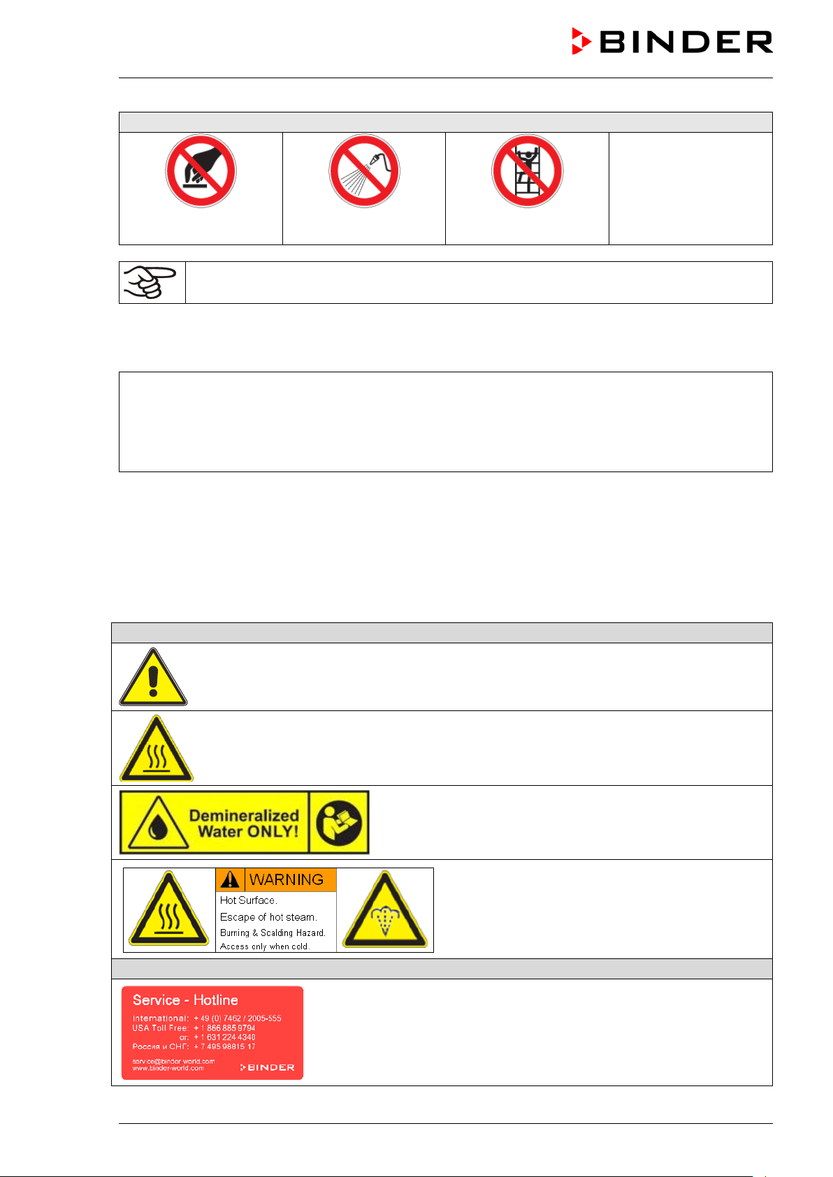
1.3 Localization / position of safety labels on the chamber
The following labels are located on the chamber:
Risk of injury (on outer door, only KBF-S-UL).
Observe the safety instructions in the operating manual.
Hot surface (on chamber door)
Observe the prescribed freshwater quality
(on the freshwater can)
Burning and scalding hazard (chamber rear)
KBF-S (E6) 08/2018 page 7/88
Page 8
Built
70 °C
158 °F
20
DIN 12880
3.1
9
2018
1
200
20
1 N ~
CONSTANT
KBF-S
E6
Serial No. 00000000000000
Made in Germany
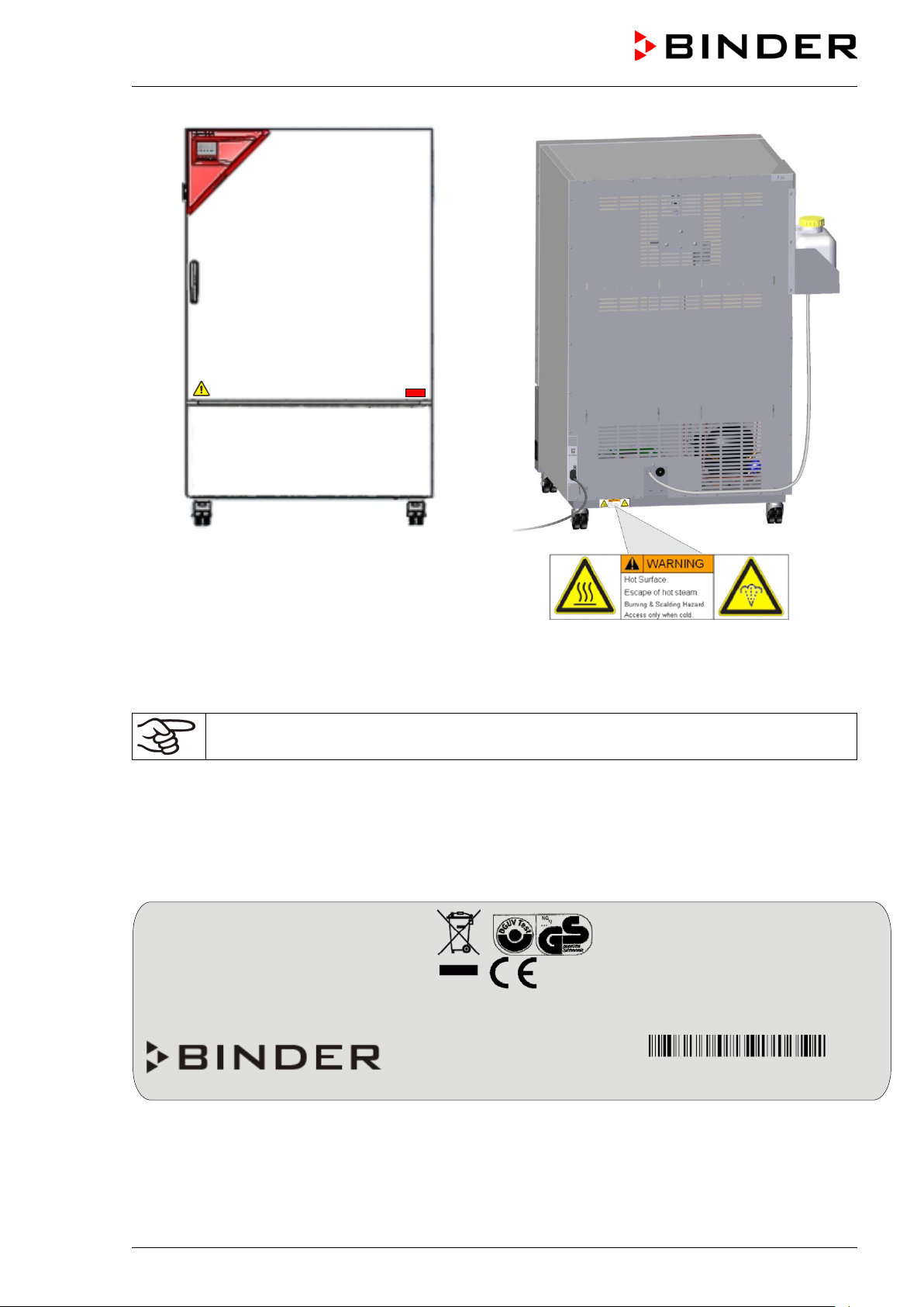
Figure 1: Position of labels on the chamber front
Figure 2: Position of label on the chamber rear
(KBF-S-UL)
Keep safety labels complete and legible.
Replace safety labels that are no longer legible. Contact BINDER Service for these replacements.
1.4 Type plate
The type plate sticks to the left side of the chamber, bottom right-hand.
Nominal temp.
IP protection
Safety device
Class
Art. No.
Project No.
020-0366
,40 kW / 8,5 A
-230 V / 50 Hz
0-230 V / 60 Hz
CLIMATE CHAMBER
BINDER GmbH
Im Mittleren Ösch 5
78532 Tuttlingen / Germany
www.binder-world.com
Max. operating pressure 15 bar
R 134A – 0,27 kg
Contains fluorinated
greenhouse gases covered
by the Kyoto Protocol
240
Figure 3: Type plate (example KBF-S 240 regular chamber 9020-0366)
KBF-S (E6) 08/2018 page 8/88
Page 9

Indications of the type plate (example)
Information
BINDER
Manufacturer: BINDER GmbH
KBF-S 240
Model designation
Constant climate chamber
Device name
Serial No.
00000000000000
Serial no. of the chamber
Built
2018
Year of construction
Nominal temperature
70 °C / 158 °F
Nominal temperature
IP protection
20
IP type of protection acc. to standard EN 60529
Temperature safety device acc. to standard DIN
12880:2007
Class
3.1
Class of temperature safety device
Art. No.
9020-0366
Art. no. of the chamber
Project No.
---
Optional: Special application acc. to project no.
1,40 kW
Nominal power
8,5 A
Nominal current
200-230 V / 50 Hz
200-230 V / 60 Hz
1 N ~
Current type
Max operating pressure in the refrigerating system
(15 bar / 218 PSI)
R 134A - 0,27 kg
Refrigerant type and filling weight
With option internal socket:
Nominal power: 0,90 kW
With option internal socket: increased total nominal
power
Contains fluorinated greenhouse gases covered by the Kyoto Protocol
Symbol on the type plate
Information
Nominal temp.
Built
70 °C
158 °F
20
DIN 12880
3.1
9
2018
1
200
20
1 N ~
CONSTANT CLIMATE CHAMBER
KBF-S
E6
Serial No. 00000000000000
Made in Germany
IP protection
Safety device
Class
Art. No.
Project No.
120-0366
,40 kW / 8,5 A
-230 V / 50 Hz
0-230 V / 60 Hz
Figure 4: Type plate (example KBF-S 240 optional chamber 9120-0366)
Temp. safety device DIN 12880
BINDER GmbH
Im Mittleren Ösch 5
78532 Tuttlingen / Germany
www.binder-world.com
Max. operating pressure 15 bar
R 134A – 0,27 kg
Contains fluorinated
greenhouse gases covered
by the Kyoto Protocol
With option internal socket:
240
Nominal power: 1,90 kW
Max. operating pressure 15 bar
Nominal voltage range +/-10%
at the indicated power frequency
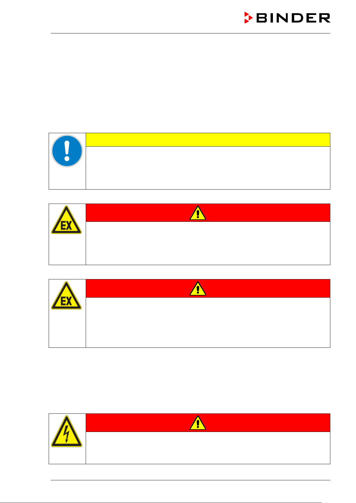
CE conformity marking
Electrical and electronic equipment manufactured / placed on the market
in the EU after 13 August 2005 and be disposed of in separate collection
according to Directive 2012/19/EU on waste electrical and electronic
equipment (WEEE).
GS mark of conformity of the “Deutsche Gesetzliche Unfallversicherung
e.V. (DGUV), Prüf- und Zertifizierungsstelle Nahrungsmittel und
Verpackung im DGUV Test“ (German Social Accident Insurance
(DGUV), Testing and Certification Body for Foodstuffs and Packaging
Industry in DGUV Test).
KBF-S (E6) 08/2018 page 9/88
Not valid for UL chambers.
Page 10
explosive at
1.5 General safety instructions on installing and operating the chambers
With regard to operating the chambers and to the installation location, please observe the DGUV guidelines 213-850 on safe working in laboratories (formerly BGI/GUV-I 850-0, BGR/GUV-R 120 or ZH 1/119,
issued by the employers’ liability insurance association) (for Germany.
BINDER GmbH is only responsible for the safety features of the chamber provided skilled electricians or
qualified personnel authorized by BINDER perform all maintenance and repair, and if components relating to chamber safety are replaced in the event of failure with original spare parts.
To operate the chamber, use only original BINDER accessories or accessories from third-party suppliers
authorized by BINDER. The user is responsible for any risk caused by using unauthorized accessories.
CAUTION
Danger of overheating.
Damage to the chamber.
∅ Do NOT install the chamber in unventilated recesses.
Ensure sufficient ventilation for dispersal of the heat.
Do not operate the chambers in hazardous locations.
DANGER
Explosion hazard.
Danger of death.
∅ Do NOT operate the chamber in potentially explosiv e areas.
∅ KEEP explosive dust or air-solvent mixtures AWAY from the chamber.
The chambers do not dispose of any measures of explosion protection.
DANGER
Explosion hazard.
Danger of death.
∅ Do NOT introduce any substance into the chamber which is combustible or
working temperature.
∅ NO explosive dust or air-solvent mixture in the i nner chamber.
Any solvent contained in the charging material must not be explosive or inflammable. I.e., irrespective of
the solvent concentration in the steam room, NO explosive mixture with air must form. The temperature
inside the chamber must lie below the flash point or below the sublimation point of the charging material.
Familiarize yourself with the physical and chemical properties of the charging material, as well as the
contained moisture constituent and its behavior with the addition of heat energy and hum i dity.
Familiarize yourself with any potential health risks caused by the charging material, the contained moisture constituent or by reaction products that may arise during the temperature process. Take adequate
measures to exclude such risks prior to putting the chamber into operation.
DANGER
Electrical hazard.
Danger of death.
∅ The chamber must NOT become wet during operation or maintenance.
KBF-S (E6) 08/2018 page 10/88
Page 11
The chambers were produced in accordance with VDE regulations and were routinely tested in accordance to VDE 0411-1 (IEC 61010-1).
During and shortly after operation, the temperature of the inner surfaces almost equals the set-point.
CAUTION
The inner chamber will become hot during operation.
Danger of burning.
∅ Do NOT touch the inner surfaces or the charging material during operation.
WARNING
Stability hazard.
Danger of injury.
Damage to the chamber and the charging material.
Housing cover breakaway.
∅ Do NOT climb on the lower housing cover.
∅ Do NOT load the lower housing cover and the door with heavy objects while the cham-
ber door is open.
1.6 Intended use
Constant climate chambers series KBF-S are suitable for exact conditioning of harmless materials. A
mixture of any component of the charging material with air must NOT be explosive. The operating temperature must lie below the flash point or below the sublimation point of the charging material. Any component of the charging material must NOT be able to release toxic gases.
Other applications are not approved.
The chambers are not classified as medical devices as defined by the Medical Device Directive
93/42/EEC.
Following the instructions in this operating manual and conducting regular maintenance work
(chap. 21) are part of the intended use.
DANGER
Explosion or implosion hazard.
Danger of poisoning.
Danger of death.
∅ Do NOT introduce any substance combustible or explosive at working temperature into
the chamber, in particular no energy sources such as batteries or lithium-ion batteries.
∅ NO explosive dust or air-solvent mixture in the inner chamber.
∅ Do NOT introduce any substance which could lead to release of toxic gases.
The charging material shall not contain any corrosive ingredients that may damage the machine components made of stainless steel, aluminum, and copper. Such ingredients include in
particular acids and halides. Any corrosive damage caused by such ingredients is excluded
from liability by BINDER GmbH.
KBF-S (E6) 08/2018 page 11/88
Page 12

WARNING: If customer should use a BINDER chamber running in non-supervised continuous operation, we strongly recommend in case of inclusion of irrecoverable specimen or
samples to split such specimen or samples and store them in at least two chambers, if this is
feasible.
In case of foreseeable use of the chamber there is no risk for the user through the integration of the
chamber into systems or by special environmental or operating conditions in the sense of EN 610101:2010. For this, the intended use of the chamber and all its connections must be observed.
1.7 Operating instructions
Depending on the application and location of the chamber, the operator of the chamber must provide the
relevant information for safe operation of the chamber in a set of operating instructions.
Keep these operating instructions with the chamber at all times in a place where they are
clearly visible. They must be comprehensible and written in the language of the employees.
1.8 Measures to prevent accidents
The operator of the chamber must observe the following rule: “Betreiben von Arbeitsmitteln. Betreiben
von Kälteanlagen, Wärmepumpen und Kühleinrichtungen“ (Operation of work equipment. Operation of
refrigeration systems, heat pumps and refrigeration equipment) (GUV-R 500 chap. 2.35) (for Germany).
The manufacturer took the following measures to prevent ignition and explosions:
• Indications on the type plate
See operating manual chap. 1.4.
• Operating manual
An operating manual is available for each chamber.
• Overtemperature monitoring
The chamber is equipped with a temperature display, which can be read from outside.
The chamber is equipped with an additional safety controller (temperature safety device class 3.1 acc.
to DIN 12880:2007). Visual and audible (buzzer) signals indicate temperature exceeding.
• Safety, measurement, and control equipment
The safety, measuring, and control equipment is easily accessible.
• Electrostatic charge
The interior parts are grounded.
• Non-ionizing radiation
Non-ionizing radiation is not intentionally produced, but released only for technical reasons by electrical equipment (e.g. electric motors, power cables, solenoids). The machine has no permanent magnets. If persons with active implants (e.g. pacemakers, defibrillators) keep a safe distance (distance of
field source to implant) of 30 cm, an influence of these implants can be excluded with high probabil i ty.
• Protection against touchable surfaces
Tested according to EN ISO 13732-1:2008.
• Floors
See operating manual chap. 3.4 for correct installation
• Cleaning
See operating manual chap. 21.3.
KBF-S (E6) 08/2018 page 12/88
Page 13
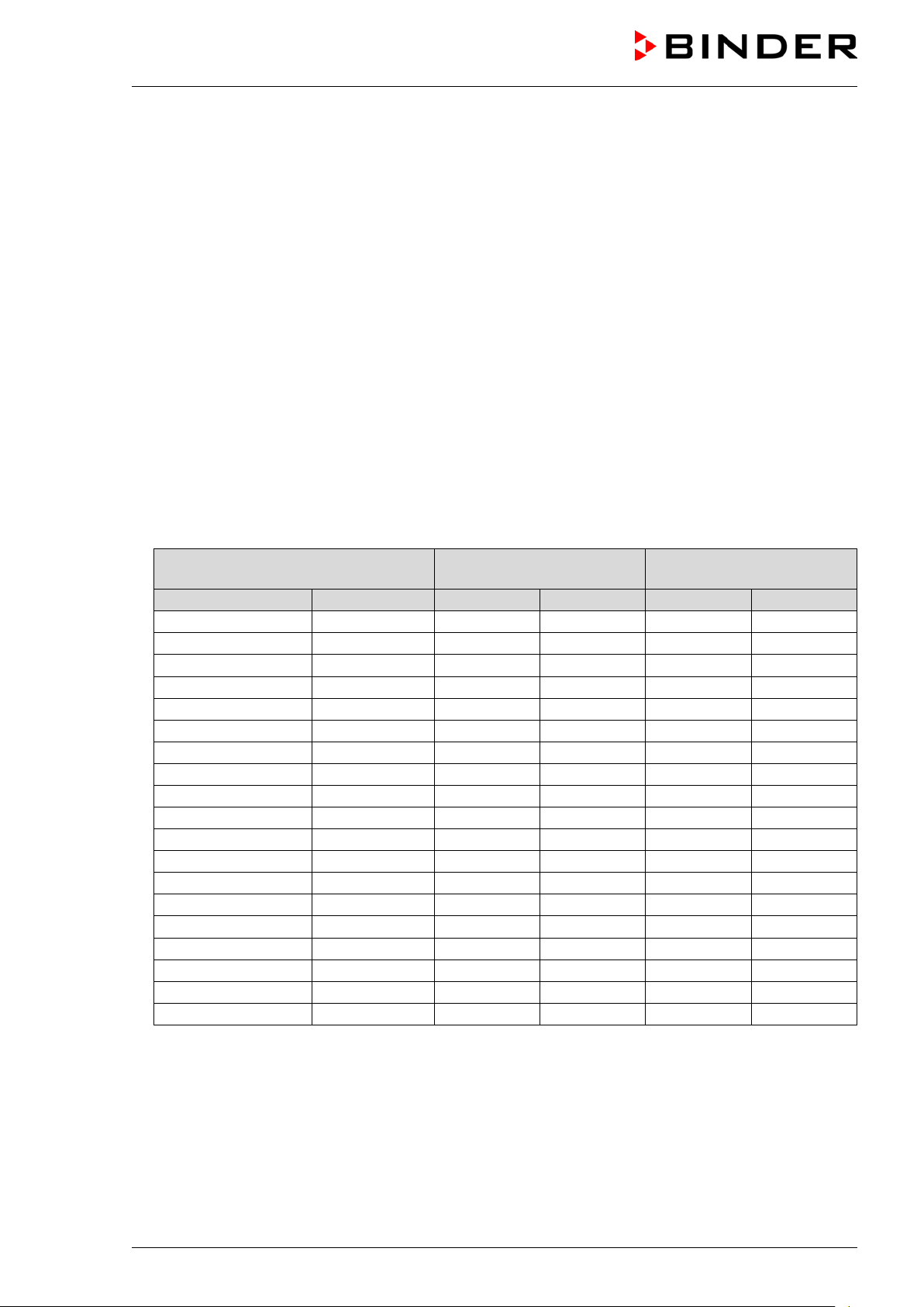
Maximum work place
threshold limit value
Tolerated concentration
with permanent load
Substance
Formula
ppm
mg/m3
ppm
mg/m3
Ammonia
NH3
20
14
5500
4000
Acetone
CH3COCH3
500
1200
3300
8000
Benzene
300
1200
150000
Chlorine
Cl2
0.5
1.5
0.7 2 Acetic acid
CH3COOH
10
25
800
2000
Ethyl acetate
CH3COOC2H5
400
1400
4000
15000
Ethanol
C2H5OH
500
960
3500
6000
Ethylene glycol
HOCH2CH2OH
10
26
1200
3000
Formaldehyde
HCHO
0.3
0.37
2400
3000
Isopropanol
(CH3)2CHOH
200
500
4800
12000
Methanol
CH3OH
200
260
3500
6000
Methyl ethyl ketone
C2H5COCH3
200
590
3300
8000
Ozone
O3
0.1
0.2
0.5 1 Hydrochloric acid
HCl 2 3
300
500
Hydrogen sulphide
H2S
10
15
350
500
Nitrogen oxides
NOx
5 9 5 9 Sulphur dioxide
SO2
5
13 5 13
Toluol
C6H5CH3
100
380
1300
5000
Xylene
C6H4(CH3)2
100
440
1300
5000
• Examinations
The chamber has been inspected by the “Deutsche Gesetzliche Unfallversicherung e.V. (DGUV)
(German Social Accident Insurance (DGUV)” (German Social Accident Insurance (DGUV), Testing
and Certification Body for Foodstuffs and Packaging Industry in DGUV Test) and bears the GS mark.
Not valid for UL chambers.
1.9 Resistance of the humidity sensor against harmful substances
The following list of harmful substances refers only to the humidity sensor and does not include any other
materials incorporated in the chamber or prohibited substances in relation to explosion protection.
Some gases - especially clean gases - do not have any influence on the humidity sensor. Others do have
a very small influence, whereas others may influence the sensor to a larger extent.
• The following gases do not influence the sensor and the humidity measurement: Argon (Ar), carbon
dioxide (CO
• The following gases do not or to a minor extent influence the sensor and the humidity measurement:
Butane (C
• The following gases do not, or to a minor extent influence the sensor and the humidity measurement,
provided that the indicated loads are not exceeded:
),helium (He), hydrogen (H2), neon (Ne), nitrogen (N2), nitrous oxide (N2O), oxygen (O2)
2
), ethane (C2H6), methane (CH4), natural gas propane (C3H8)
4H10
These values are to be considered as approximate values. The sensor resistance largely depends on
the temperature and humidity conditions during the time of exposure to harmful substances. Avoid
simultaneous condensation. Tolerated error of measurement: ± 2 %r.H. The maximum work place
threshold limit value is one that can be regarded as harmless for humans.
• Vapors of oil and fat are dangerous for the sensor because they may condensate at the sensor and
thus prevent its function (insulating layer). For similar reasons it is not possible to measure smoke
gases.
KBF-S (E6) 08/2018 page 13/88
Page 14

2. Chamber description
The constant climate chambers KBF-S ar e equipped with a multifunctional microprocessor display controller with 2-channel technology for temperature and humidity plus a digital display accurate to one-tenth
of a degree resp. 0.1% r.h.
With its microprocessor controlled humidifying and dehumidifying system the KBF-S is a high-precision
constant climate chamber.
The KBF-S meets the “Long term testing” and “Accelerated testing” requirements for climatic chambers
acc. to ICH guideline CPMP/ICH/2736/99 (Q1A).
Furthermore, it permits simulating exactly and over long periods constant conditions for other applications
such as sample conditioning for material testing of paper, textiles, plastics, building material s, etc.
Freshwater is supplied by manually filling a freshwater can which shall be placed inside the supplied
standard water can support. In addition a magnetic support adjustable in height is optionally availabl e.
The APT.line™ preheating chamber system guarantees high level of spatial and time-based temperature
precision, thanks to the direct and distributed air circulation into the interior. The fan supports exact attainment and maintenance of the desired temperature accuracy.
A resistance humidifying system humidifies the air. For this purpose, use deionized (demineralized) water. The option BINDER Pure Aqua Service allows using the chamber with any degree of water hardness.
The inner chamber, the pre-heating chamber and the interior side of the doors are all made of stainless
steel V2A (German material no. 1.4301, US equivalent AISI 304). The housing is RAL 7035 powdercoated. All corners and edges are also completely coated.
All chamber functions are easy and comfortable to use thanks to their clear arrangement. Major features
are easy cleaning of all chamber parts and avoidance of undesired contamination.
The efficient RD4 chamber controller is equipped with a multitude of operating functions, in addition to
recorder and alarm functions. Set-point entry is easily accomplished directly via the chamber controller
and is also possible directly with a computer via Intranet in connection with the communication software
APT-COM™ 3 DataControlSystem (option, chap. 20.1). The constant climate chamber comes equipped
with an Ethernet serial interface for computer communication and with a USB interface. In addition, the
BINDER communication software APT-COM™ 3 permits networking up to 40 chambers and connecting
them to a PC for controlling and programming, as well as recording and representing temperature and
humidity data. For further options, see chap.24.5.
The chambers size 240 and 720 are equipped with four castors. Both front castors can be easily locked
via the attached brakes.
Temperature range: 0 °C / 32 °F up to 70 °C / 158 °F, humidity range: 10% r.h. to 80% r.h.
For the control ranges of temperature and humidity, see climatic diagrams (chap. 18).
KBF-S (E6) 08/2018 page 14/88
Page 15
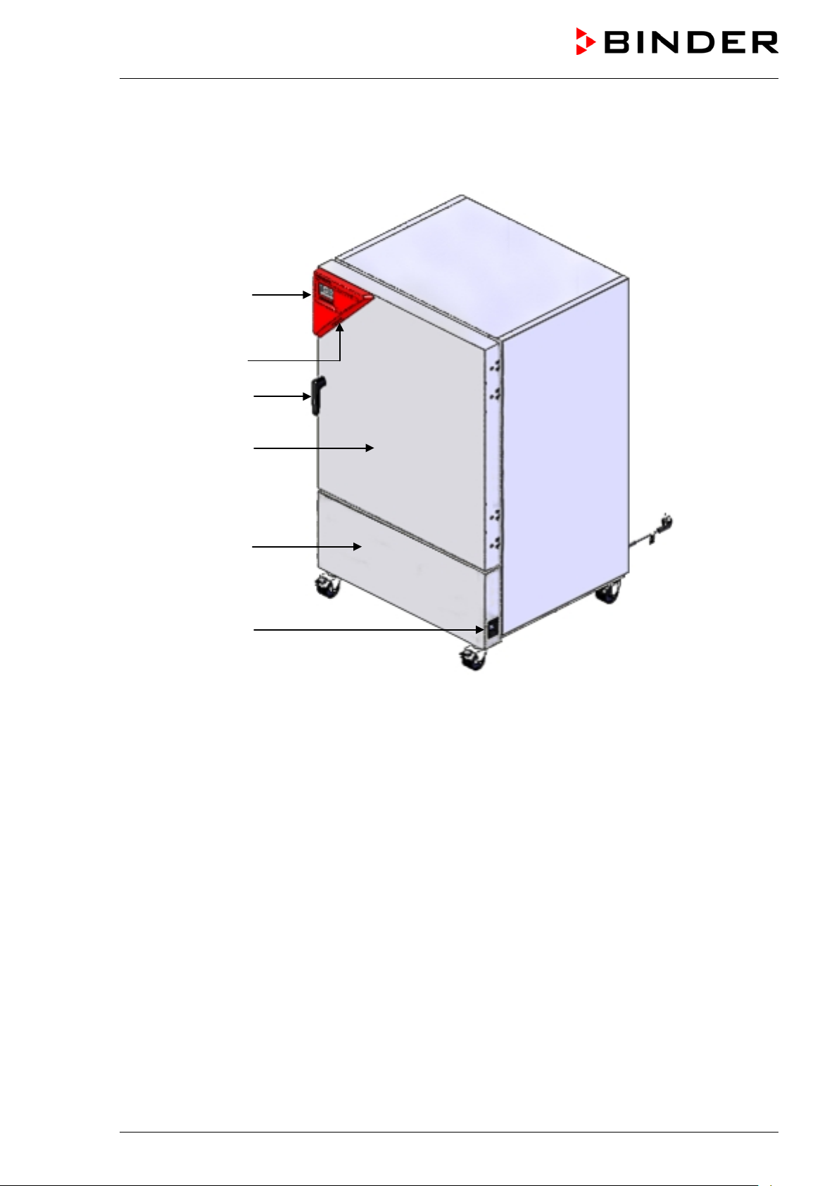
(2)
2.1 Chamber overview
(3)
(4)
(5)
(6)
(1)
Figure 5: Constant climate chamber KBF-S size 240
(1) Main power switch
(2) Instrument panel with RD4 chamber controller and USB interface
(3) USB interfaces
(4) Door handle
(5) Chamber door
(6) Refrigerating machine and humidity generation module
KBF-S (E6) 08/2018 page 15/88
Page 16

2.2 Rear chamber view
(10)
(7)
(8)
(11)
(12) (9)
Figure 6: Rear view of the chamber (example: KBF-S 240)
(7) Freshwater can with can support
(8) Hose leading to the freshwater can
(9) Hose fixing devices
(10) Ethernet interface
(11) Power cable
(12) Condensate collection pan
(9)
KBF-S (E6) 08/2018 page 16/88
Page 17

3. Completeness of delivery, transportation, storage, and installa-
tion
3.1 Unpacking, and checking equipment and completeness of delivery
After unpacking, please check the chamber and its optional accessories, if any, based on the delivery
receipt for completeness and for transportation damage. Inform the carrier immediately if transportation
damage has occurred.
The final tests of the manufacturer may have caused traces of the shelves on the inner surfaces. This
has no impact on the function and performance of the chamber.
Please remove any transportation protection devices and adhesives in/on the chamber and on the doors
and remove the operating manuals and accessory equipment.
CAUTION
Sliding or tilting of the chamber.
Damage to the chamber.
Risk of injury by lifting heavy loads.
∅ Do NOT lift or transport the chamber using the door, the handl e, or the lower housing.
Lift chambers size 240 from the pallet at the four lower corners with the aid of six peo-
ple or with a fork lifter. Set the fork lifter only from t he front or rear in the middle of the
chamber.
Lift the chambers size 720 from the pallet using technical devices (fork lifter). Set the
fork lifter only from the front or rear in the middle of the chamber.
∅ Do NOT set the fork lifter from the chamber side.
If you need to return the chamber, please use the original packing and observe the guidelines for safe
lifting and transportation (chap. 3.2).
For disposal of the transport packing, see chap. 22.1.
Note on second-hand chambers (Ex-Demo-Units):
Second-hand chambers are chambers that were used for a short time for tests or exhibitions. They are
thoroughly tested before resale. BINDER ensures that the chamber is technically sound and will work
flawlessly.
Second-hand chambers are marked with a sticker on the chamber door. Please remove the sticker before commissioning the chamber.
KBF-S (E6) 08/2018 page 17/88
Page 18
3.2 Guidelines for safe lifting and transportation
The front castors of the chambers size 240 and 720 can be blocked by brakes. After operation, please
observe the guidelines for temporarily decommissioning the chamber (chap. 22.2). Please move the
chambers with castors only when empty and on an even surface, otherwise the castors may be damaged.
CAUTION
Sliding or tilting of the chamber.
Damage to the chamber.
Risk of injury by lifting heavy loads.
Transport the chamber in its original packaging only.
For moving or shipping, secure the constant climate chamber with transport straps.
∅ Do NOT lift or transport the chamber using the door, the handle, or the lower housing.
Lift chambers size 240 at the four lower corners with the aid of 6 people or with a fork
lifter. Set the fork lifter only from the front or rear in the middle of the chamber.
Lift the chambers size 720 using technical devices (fork lifter). Set the fork lifter only
from the front or rear in the middle of the chamber.
∅ Do NOT set the fork lifter from the chamber side.
You can order transport packing for moving or shipping purposes from BINDER service.
Permissible ambient temperature range during transport:
• If the steam humidifying system has NOT been emptied: +3 °C / 37.4 °F to +60 °C / 140 °F.
• After BINDER Service has emptied the steam humidifying system: -10 °C / 14 °F to +60 °C / 140 °F.
With temperatures below +3 °C / 37.4 °F, water must be completely removed from the humidifying system.
CAUTION
Transport below +3 °C / 37.4 °F with filled steam humidifying system.
Freezing in the steam generator.
Damage to the chamber.
Contact BINDER Service before any transportation below +3 °C / 37.4 °F.
3.3 Storage
Intermediate storage of the chamber is possible in a c losed and dry room. Observe the guidelines for
temporary decommissioning (chap. 22.2).
Permissible ambient temperature range during storage:
• If the steam humidifying system has NOT been emptied: +3 °C / 37.4 °F to +60 °C / 140 °F.
• After BINDER Service has emptied the steam humidifying system: -10 °C / 14 °F to +60 °C / 140 °F
KBF-S (E6) 08/2018 page 18/88
Page 19

empty the
With temperatures below +3 °C / 37.4 °F, water must be completely removed from the humidifying system.
CAUTION
Storage below +3 °C / 37.4 °F with filled steam humidifying system.
Freezing in the steam generator.
Damage to the chamber.
Contact BINDER Service before any transportation below +3 °C / 37.4 °F.
Permissible ambient humidity: max. 70 % r.H., non-condensing
CAUTION
Condensation by excess humidity.
Danger of corrosion on the housing after operating at humidity values > 70 % r.H.
for a long period.
Dry the chamber completely before shut-down:
• Set the humidity to 0 % r.H. To enable dehumidification, the humidifying and dehumidifying system must be activated (deactivated function “Humidity off”, chap. 8).
• Set the temperature set point to 60 °C / 140 °F for approx. 2 hours.
• Only then, shut down the chamber at the main power switch (1) and
freshwater can.
When after storage in a cold location you transfer the chamber to its warmer installation site, condensation may form. Before start-up, wait at least one hour until the chamber has attained ambient temperature
and is completely dry.
In case of a prolonged temporal decommissioning: Leave the chamber door open or remove the access
port plugs.
3.4 Location of installation and ambient conditions
Set up the constant climate chamber on a flat, even surface, and in a well-ventilated, dry location and
align it using a spirit level. The site of installation must be capable of supporting the chamber’s weight
(see technical data, chap.24.4). The chambers are designed for setting up inside a building (indoor use).
CAUTION
Danger of overheating.
Damage to the chamber.
∅ Do NOT set up chamber in non-ventilated recesses.
Ensure sufficient ventilation for dispersal of the heat.
• Permissible ambient temperature range during operation: +18 °C / 64.4 °F to +32 °C / 89.6 °F. At
elevated ambient temperature values, fluctuations in temperature can occur.
The ambient temperature should not be substantially higher than the indicated ambient temperature of +22 °C +/- 3 °C / 71.6 °F +/- 5.4 °F to which the specified technical data relat e.
Deviations from the indicated data are possible for other ambient conditions.
With each degree of ambient temperature >25 °C / 77 °F, the refrigeration power decreases
by 1.5 K.
KBF-S (E6) 08/2018 page 19/88
Page 20

CAUTION
• Permissible ambient humidity: 70 % r.H. max., non-condensing
When operating the chamber at temperature set-points below ambient temperature, high ambient humidity may lead to condensation on the chamber.
• Installation height: max. 2000 m / 6562 ft. above sea level.
Water supply is provided by manually filling the freshwater can (chap. 4.1).
To avoid any possible water damage, provide a floor drain at the location of the devi ce. S el ect
a suitable installation site to avoid any consequential damage by splashing water.
When placing several chambers of the same size side by side, maintain a minimum distance of 250 mm /
9.84 in between each chamber. Wall distances: rear 100 mm / 3.9 in, sides 160 mm / 6.29 in. Spacing
above the chamber of at least 100 mm / 3.9 in must also be accounted for.
Maximum load of the top of the housing: 15 kg / 33 lb.
Danger by stacking.
Damage to the chambers.
∅ Do NOT place the chambers on top of each other.
To completely separate the chamber from the power supply, you must disconnect the power plug. Install
the chamber in a way that the power plug is easily accessible and can be easily pulled in case of danger.
For the user there is no risk of temporary overvoltages in the sense of EN 61010-1:2010.
With an increased amount of dust in the ambient air, clean the condenser fan (by suction or blowing)
several times a year.
Avoid any conductive dust in the ambiance according to the chamber layout complying with pollution de-
gree 2 (IEC 61010-1).
Do not install or operate the chamber in potentially explosive areas.
DANGER
Explosion hazard.
Danger of death.
∅ Do NOT operate the chamber in potentially explosive areas.
KEEP explosive dust or air-solvent mixtures AWAY from the v i cinity of the chamber.
DANGER
Electrical hazard.
Danger of death.
∅ Do NOT install any electrical wiring or components under the unit.
Install the chamber in a way that freshwater can is easily accessible for filling.
KBF-S (E6) 08/2018 page 20/88
Page 21

Bringing a source of humidity
4. Installation and connections
4.1 Water supply
Freshwater is supplied by manually filling a freshwater can. It is not possible to connect the chamber
directly to a water pipe.
The freshwater can has a volume of 10 liters / 0.36 cu.ft. and will be placed inside a water can support.
To guarantee humidification during 24 hours even at high humidity set-points, we recommend
filling the freshwater can daily at the end of the day.
When the freshwater can is empty, the message “Freshwater supply” will be displayed on the controller
(chap. 13.1), the buzzer sounds, and the humidification module turns off. After acknowledging the alarm,
the humidification module tries to fill up and start operating.
Emerging condensation water is collected in a collection pan below the chamber.
Regularly check the filling level of the condensate collection pan.
into the inner chamber may increase wastewater production.
Water consumption: The maximum is 1 liter per day. At 40 °C and 75 % r.h. without door opening: approx. 100 ml per day.
4.1.1 Types of suitable water quality
• Deionized water from a water treatment installation already existing at the customer's site. Conductivity from 1 µS /cm up to a maximum of 20 µS/cm. (Water, which is in equilibrium with the CO
and has a conductivity below 1 µS/cm (ultrapure water), may cause acid corrosion due to its low pH).
• Tap water that has been treated by the optional water treatment system BINDER Pure Aqua Service
(disposable system). A reusable measuring equipment to assess the water quality is included (chap.
0).
BINDER GmbH is NOT responsible for the water quality at the user’s site.
Any problems and malfunctions that might arise following use of water of deviati ng qual i ty is
excluded from liability by BINDER GmbH.
The warranty becomes void in the event of use of water of deviating quality .
in the air,
2
CAUTION
Calcification of the humidifying system.
Damage to the chamber.
Operate the chamber with deionized (demineralized) water only.
Water intake temperature NOT below +5 °C / 41 °F and not exceeding 40 °C / 104 °F.
4.1.2 BINDER Pure Aqua Service (option)
The optional BINDER water treatment system (disposable system) is available to treat tap water. The
lifetime depends on water quality and the amount of treated water used. The measuring equipment to
assess the water quality is reusable.
KBF-S (E6) 08/2018 page 21/88
Page 22

As long as no hose is connected to the tap of the freshwater can, the tap must
or fill it
on site with a suitable aid (water hose, watering can). When filling on site, the
: Freshwater can with closed tap
Loosen 4 screws on the
chamber’s rear panel,
attach the can support
mounting plate and tighten
ng the
mounting
Insert the four hooks of the can support into
can
For detailed information on operating the water treatment system BINDER Pure Aqua Service and its function, please refer to the operating manual supplied with BINDER Pure Aqua Service.
4.1.3 Installation of freshwater supply
To install the freshwater can proceed in the following order:
1. Fill the freshwater can.
be closed
Observe water quality and temperature (chap. 4.1.1).
For refilling later, you can remove the freshwater can from the support
existing hose connection can remain on the freshwater can.
Figure 7
2. Establish the hose connection to the freshwater can
The freshwater hose (2 mm wall thickness) is firmly connected to the chamber. Attach the free
hose end to the connection of the freshwater can and secure it at the top and bottom with the 2
supplied hose clamps.
3. Attach the can support mounting plate at the left side of the climatic chamber
the screws again.
Screws
Figure 8: Attachi
can support
plate
4. Attach the can support to the can support mounting plate
the provided eyelets of the can support holder
Figure 9: Attaching the can support to the
support mounting plate
KBF-S (E6) 08/2018 page 22/88
Page 23

Figure 10: Can support mounting plate and can support, mounted
Can support mounting plate
Can support
5. Insert the freshwater can from above into the can support.
6. Mount the hose holders and fix the hose
Fix the hose to the hose holders on the chamber rear in a way that it cannot bend.
(7a) Can support mounting plate
(7b) Freshwater can
(7c) Can support
(8)
(9)
Figure 11: Rear chamber view (detail) with installed water supply
(7) Freshwater can (7b) inside the can support (7c) with mounted can support mounting plate
(8) Hose leading to the freshwater can
(9) Hose fixing devices
KBF-S (E6) 08/2018 page 23/88
Page 24

To operate the chamber with humidity, the freshwater can tap must be open
freshwater
. As a result, obstruction of the water supply due to negative pressure inside the
The freshwater can outlet must NOT be placed on or above the rear panel of the chamber.
DANGER
Entry of water via the rear panel into the chamber
Electrical hazard.
Danger of death.
Damage to the chamber.
The regular support may only be attached on the left side of the chamber.
The magnetic support adjustable in height (option) may only be attached on the front or
on the left side of the chamber.
∅ Do NOT place the freshwater can tap on or above the rear panel of the chamber
(chap. 6).
Do not firmly close the lid of the freshwater can to allow air to enter the
can
can is avoided.
Figure 12: Freshwater can with open tap
KBF-S (E6) 08/2018 page 24/88
Page 25

4.2 Condensate collection pan
The emerging condensate is collected in a condensate collection pan which is mounted under the chamber. If necessary, the pan can be removed and emptied at any time..
KBF-S 115 KBF-S 240, 720, 1020
Figure 13: Condensate collection pan
4.2.1 KBF-S 115: Installation of the condensate collection pan
Hang the condensate collection pan on the chamber rear and guide the hose through the latch of the
holder.
Figure 14: KBF-S 115 with mounted condensate collection pan
KBF-S (E6) 08/2018 page 25/88
Page 26
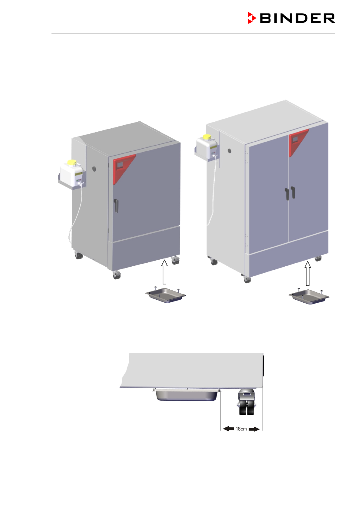
4.2.2 KBF-S 240, 720, 1020: Installation of the condensate collection pan
Place the condensate collection pan with the magnetic holders on the bottom of the chamber.
Insert the pan in a way that it is flush with the front edge of the chamber and the distance to the right
edge of the device is 18 +/- 2 cm.
KBF-S 240 KBF-S 720
Figure 15: Mounting the condensate collection pan to the chamber
Figure 16: Positioning the condensate collection pan (front view)
KBF-S (E6) 08/2018 page 26/88
Page 27
4.3 Electrical connection
The chambers are supplied ready for connection. They come with a fixed power connection cable of at
least 1800 mm / 70.87 in in length.
Model version
KBFS240-230V
KBFS720-230V
KBFS240UL-240V
KBFS720UL-240V
• The domestic socket must also provide a protective conductor. Make sure that the connection of the
protective conductor of the domestic installations to the chamber’s protective conductor meets the latest technology. The protective conductors of the socket and plug must be compatible!
• Prior to connection and start-up, check the power supply voltage. Compare the values to the specified
data located on the chamber’s type plate (left chamber side, bottom right-hand, see chap. 1.4).
• When connecting, please observe the regulations specified by the local electricity supply company
and as well as the VDE directives (for Germany). We recommend the use of a residual current circuit
breaker.
• Pollution degree (acc. to IEC 61010-1): 2
• Installation category (acc. to IEC 61010-1): II
Art. No.
(x = 0 or 1)
9x20-0366
9x20-0368
9x20-0367
9x20-0369
Power plug
Grounded
plug
NEMA 6-20P
Voltage +/-10% at the
indicated power fre-
quency
200-230 V at 50 Hz
200-230 V at 60 Hz
200-240 V at 50Hz
200-240 V at 60Hz
Current
type
1N~ 16 Amp
2~ 16 Amp
Chamber
fuse
CAUTION
Danger of incorrect power supply voltage.
Damage to the equipment.
Check the power supply voltage before connection and start-up.
Compare the power supply voltage with the data indicated on the type plate.
See also electrical data (chap. 24.4).
To completely separate the chamber from the power supply, you must disconnect the power
plug. Install the chamber in a way that the power plug is easily accessible and can be easily
pulled in case of danger.
Remark when operating the chamber with a power frequency of 60 Hz:
WARNING
High leakage current.
Electrical hazard.
Earth connection is essential before connecting supply. Check socket before inserting
plug.
When connected to a power supply 1N~ with a frequency of 60 Hz, a leakage current of more than 3.5
mAmp is possible. If grounding through the power cable is insufficient or missing, the leakage current
may flow through the user’s body. Correct installation of the professional grade power socket provided by
the user safely avoids this. Before connecting the chamber to the socket, please check its grounding
contact type plug for appropriate construction and if it is undamaged.
KBF-S (E6) 08/2018 page 27/88
Page 28

Status icons
Temp. / Humidity
Icon
Signification
Icon
Signification
Icon
Signification
Function
5. Functional overview of the RD4 chamber controller
The RD4 chamber controller controls following parameters inside the chamber:
• Temperature in °C
• Relative humidity in % r.h.
For the control ranges of temperature and humidity, see climatic diagrams (chap. 18).
You can enter the desired set point values in the “Set points” menu directly at the controller or use the
APT-COM™ 3 DataControlSystem software (option) specially developed by BINDER.
The controller offers various notifications and alarm messages with visual and audible indication. All con-
troller setting remain valid until the next manual change. They are stored also after turning off the chamber.
Temperature values
Humidity values
Text information
Figure 17: Normal display of the RD4 controller (sample values)
Status icons in the controller display
Heating active
Refrigeration active
Display of activated special controller functions.
1 = Humidity off
Collective alarm
Information
Functional controller keys
Arrow-up button
Arrow-down button
OK button
Back button
Standby button
KBF-S (E6) 08/2018 page 28/88
• Navigate between menus, submenus, other functions
• In the setting menu: change setting, decrease value
• Navigate between menus, submenus, other functions
• In the setting menu: change setting, increase value
• Select menu, submenu, function
• In the setting menu: Confirm entry
Back to previous menu level
no function
Page 29

ce ranger limits and delay time for
5.1 Menu structure of the controller and access levels
Starting from Normal display, navigate between the menus with the arrow buttons.
With the OK button you enter the setting of further subordinate menu functions.
With the Back button you go back to the previous function and finally back to Normal display.
The available functions depend on the current dependent on the current authorization “User”, “Admin” or
“Service”, for which the entry of a password may be required, depending on the setting.
You can set passwords for different access levels:
• User: The password enables access to the standard operating functions. Factory setting is 00 00 (no
password assigned).
• Admin: The password enables access to advanced controller functions and settings. Factory setting
is 00 01.
• Service: The password enables access to all controller functions (for BINDER Service only).
As soon as a password has been assigned, access to the respective functions is blocked and only available after entering the correct password.
Menu Required access level Functions
Setpoints
Chamber info
Settings
Service
“User”
Any user
“Admin”
“Service”
• Temperature and humidity set-point setting
• Setting the safety controller
• Turning on / off humidity control
• Configuration display (setup information, controller
hardware and software, analog inputs)
• Display of interface configuration (e.g. MAC address,
IP address)
• General controller settings (date, time, menu language,
temperature unit, display brightness…)
• Network settings
• Setting the data logger storage interval
• Setting the toleran
tolerance range alarm
• Self-test function
• Password changing for User and Admin
• Configuration settings (only for BINDER Service)
• Password changing for User and Admin
USB
Unless noted otherwise, the figure in this manual show the functional range, which is available for the
user with “Admin” authorization level
Note: When specifying the path to the respective function, the possibly required entry of a password is
not listed
KBF-S (E6) 08/2018 page 29/88
Export: Any user
Import: “Admin”
• Export of configuration, logger, and service data
• Import of configuration data
Page 30

5.2 Performance during and after power failures
During a power failure, all controller functions are shut down.
After the power returns, all functions return to the same status the chamber had before power failure. The
set-points are immediately resumed.
If during power failure an alarm has occurred (tolerance range, safety controller etc.), confirm the alarm.
See chap. 13.
6. Start up
After connecting the power supply and filling the freshwater can, turn on the chamber by its main power
switch (1). The lit pilot lamp shows the chamber is ready for operation.
The controller shows normal display and controls temperature and humidity to the last entered values.
For operation with humidity, the humidifying and dehumidifying system m ust be act ivated (chap. 8).
For operation with humidity:
• Activate the humidifying and dehumidifying system (chap. 8).
• Open the freshwater can tap (chap. 4.1.3)
• Do not firmly close the lid of the freshwater can to allow air to enter the freshwater can. As a result,
obstruction of the water supply due to negative pressure inside the can is avoided.
After the first turning on of the chamber or after an interruption of the power supply the relative humidity
will increase after a delay of about 20 minutes. During this period, the relative humidity can drop considerably.
Warming chambers may release odors in the first few days after commissioning. This is not a quality
defect. To reduce odors quickly we recommend heating up the chamber to its nominal temperature for
one day and in a well-ventilated location.
WARNING: If customer should use a BINDER chamber running in non-supervised continuous operation, we strongly recommend in case of inclusion of irrecoverable specimen or
samples to split such specimen or samples and store them in at least two chambers, if this is
feasible.
If the function “Language selection at restart” has been activated (chap. 11.5, factory setting ON), the
following settings are checked upon start up:
• Menu language (chap. 11.1):
Use the arrow buttons to select the desired language, confirm with the OK button
• Temperature unit (chap. 11.2):
Use the arrow buttons to select the desired temperature unit, confirm with the OK button.
• Current date (chap. 11.3), format DD MM YYYY:
Use the arrow buttons to set the day, continue with the OK button.
Use the arrow buttons to set the month, continue with the OK button.
Use the arrow buttons to set the year, confirm with the OK button
• Current time (chap. 11.4), format HH:MM:
Use the arrow buttons to set the hours, continue with the OK button.
Use the arrow buttons to set the minutes, confirm with the OK button
KBF-S (E6) 08/2018 page 30/88
Page 31

Temperature
Humidity
7. Temperature and humidity set-point entry
Required access level: “User”.
Setting ranges Control ranges
Temperature
-5 °C / 23 °F up to 70 °C /
158 °F.
0 ºC / 32 °F up to 70 °C / 158 °F without humidity
10 °C / 50 °F up to 70 °C / 158 °F with humidity
10 % r.h. to 80 % r.h.
Humidity
10 % r.h. up to 80 % r.h.
See climatic diagram, chap. 18.
For the control range of temperature and relative humidity, see the temperature / humidity diagram chap.
18).
With safety controller mode “Limit”, adapt the safety controller always when you changed the
temperature set-point. Set the safety controller value by approx. 2 °C to 5 °C abov e the temperature set-point (chap. 10.2).
Recommended setting: safety controller mode “Offset” with safety controller value 2 °C.
When operating without humidity by activated function “Humidity of f” (chap. 8), set the humidity tolerance range to “0” in order to avoid tolerance range alarms (chap. 12).
7.1 Temperature set-point entry
Path: Normal display Setpoints Temperature
Press the OK button to enable the setting.
Temperature setting.
The current setting flashes. Enter the desired set-point with the arrow
buttons.
Confirm the entry with the OK button.
With the arrow-down button you can continue with the humidity set-point entry (chap. 7.2).
With the Back button you can go back to the “Setpoints” submenu and, repeatedly pressing it, to Nor-
mal display.
7.2 Humidity set-point entry
Path: Normal display Setpoints Humidity
Press the OK button to enable the setting.
Humidity setting
The current setting flashes. Enter the desired set-point with the arrow
buttons.
Confirm the entry with the OK button.
KBF-S (E6) 08/2018 page 31/88
Page 32

Functions on/off
Humidity off
Humidity off
With the arrow-up button you can go back to the temperature set-point entry (chap. 7.1)
With the arrow-down button you can now change to the special controller functions setting (chap. 8)
With the Back button you can go back to the “Setpoints” submenu and, repeatedly pressing it, to Nor-
mal display.
8. Special controller functions – Turning off the humidity system
Required access level: “User”.
Turning off humidity control in this menu is required when operating the chamber without water
connection in order to avoid humidity alarms. For further information see chap. 18.
Path: Normal display
Setpoints Functions on/off
You can define the switching state of up to 4 controller functions.
Function 1 “Humidity off” serves to turn off the humidification and dehumi di fication system
With this chamber type the other controller functions are without function .
The functions are displayed from left to right.
Example: Function 1 “Humidity off” activated = 1000. Function 1 “Humidity off” deactivated = 0000.
Submenu “Functions on/off”.
This view shows the switching states of the four available functions.
“1” = Function activated
“0” = Function deactivated
Press the OK button to access the first individual function. This is the only accessible function with this
chamber type.
Function 1 “Humidity off”.
The current switching state is shown (example).
Press the OK button to enable the setting.
With the Back button you can go back to the “Functions on/off” submenu and, repeatedly pressing it, to
Normal display.
KBF-S (E6) 08/2018 page 32/88
Setting function 1 “Humidity off”.
The current setting flashes. Use the arrow buttons to select between
0 (deactivated function) and 1 (activated function).
Confirm the setting with the OK button.
Page 33

Temp. / Humidity
Humidity off
Password
Password
Wrong password
In Normal display the activated functions are shown. The „Info“ icon flashes slowly. W hile it is lit, the lower text informs about the activated functions.
9. Password
9.1 Password request
To access menus for which access is restricted, you must enter the corresponding password.
After calling the appropriate menu function with the OK button the password request appears.
Password request.
The left two digits are flashing. Enter the desired numbers with the
arrow buttons.
Confirm the setting with the OK button.
Password request.
The right two digits are flashing. Enter the desired numbers with the
arrow buttons.
Confirm the setting with the OK button.
Upon entering an incorrect password, the message “Wrong password” is displayed.
Display “Wrong password”.
After 3 seconds the controller changes again to the password entry.
Enter the correct password.
Following correct password entry you can access the desired menu function.
KBF-S (E6) 08/2018 page 33/88
Page 34

Password User
Password User
Password Admin
Password Admin
9.2 Assign and modify a password
In this menu you can assign and modify the passwords of the “User” and “Admin” access levels.
Required access level: “Admin”.
9.2.1 Assign and modify the User password
Path: Normal display Settings Chamber Password User
Press the OK button to enable the setting.
Setting the User password.
The left two digits are flashing. Enter the desired numbers with the
arrow buttons.
Confirm the setting with the OK button.
Setting the User password.
The right two digits are flashing. Enter the desired numbers with the
arrow buttons.
Confirm the setting with the OK button.
With the arrow-down button you can now proceed to enter the Admin password.
With the Back button you can go back to the “Chamber” submenu and, repeatedly pressing it, to Nor-
mal display.
Keep the password well in mind. There is no access to the corresponding menu functions
without the correct password.
9.2.2 Assign and modify the Admin password
Path: Normal display Settings Chamber Password Admin
Press the OK button to enable the setting.
Setting the Admin password.
The left two digits are flashing. Enter the desired numbers with the
arrow buttons.
Confirm the setting with the OK button.
Setting the Admin password.
The right two digits are flashing. Enter the desired numbers with the
arrow buttons.
Confirm the setting with the OK button.
KBF-S (E6) 08/2018 page 34/88
Page 35

With the Back button you can go back to the “Chamber” submenu and, repeatedly pressing it, to Nor-
mal display.
Keep the password well in mind. There is no access to the corresponding menu functions
without the correct password.
10. Temperature safety devices
10.1 Over temperature protective device (class 1)
The chamber is equipped with an internal temperature safety device, class 1 acc. to DIN 12880:2007. It
serves to protect the chamber and prevents dangerous conditions caused by major defects.
If a temperature of approx. 110 °C / 230 °F is reached, the over temperature protective device permanently turns off the chamber. The user cannot restart the device again. The protective cut-off device is
located internally. Only a service specialist can replace it. Therefore, please contact an authorized service provider or BINDER Service.
10.2 Overtemperature safety controller class 3.1
The chambers are regularly equipped with an electronic overtemperature safety controller (temperature
safety device class 3.1 according to DIN 12880:2007). The safety controller is independent of the temperature control system. If an error occurs, it performs a regulatory function.
Please observe the DGUV guidelines 213-850 on safe working in laboratories (formerly BGI/GUV-I 8500, BGR/GUV-R 120 or ZH 1/119, issued by the employers’ liability insurance association) (for Germany).
The overtemperature safety controller serves to protect the chamber, its environment and the contents
from exceeding the maximum permissible temperature. In the case of an error, it limits the temperature
inside the chamber to the entered safety controller value. This condition (state of alarm) is indicated visually and additionally with an audible alert if the buzzer is enabled (chap. 13.2). The alarm persists until the
chamber cools down below the configured safety controller value and the alarm is reset on the controller.
Check the setting regularly and adjust it following changes of the temperature set-point or
charge.
The safety controller only activates after the set-point has been reached once.
You can set the safety controller mode to “Limit” or “Offset”.
• Limit: Limit value, absolute maximum permitted temperature value
This setting offers high safety as a defined temperature limit will not be exceeded. It is important to
adapt the safety controller value after each modification of the temperature set-point. Otherwise, the
limit could be too high to ensure efficient protection, or, in the opposite case, it could prevent the controller from reaching an entered set-point outside the limit range.
• Offset: Offset value, maximum overtemperature above any active temperature set point. The resulting
maximum temperature changes internally and automatically with every temperature set-point change.
KBF-S (E6) 08/2018 page 35/88
Page 36

Mode
Limit
Offset
Example:
Desired temperature value: 40 °C, desired safety controller value: 45 °C.
Possible settings for this example:
Temperature set point Safety controller mode Safety controller value
40 °C
Limit Limit value 45 °C
Offset Offset value 5 °C
10.2.1 Setting the safety controller mode
Required access level: “User”.
Path: Normal display
Press the OK button to enable the setting.
With the arrow-down button you proceed to setting the safety controller value (chap. 10.2.2)
With the Back button you can go back to the “Safety controller” submenu and, repeatedly pressing it, to
Normal display.
Setpoints Safety controller Mode
Setting the safety controller mode
The current setting flashes. Use the arrow buttons to select between
LIMI (Limit) and OFFS (Offset).
Confirm the setting with the OK button.
10.2.2 Setting the safety controller value
Required access level: “User”.
The desired safety controller mode must be selected first (chap. 10.2.1). Depending on the mode setting,
one of the following setting menus will appear.
Path: Normal display
Press the OK button to enable the setting.
or
Setpoints Safety controller Limit or Offset
Setting the safety controller value with “Limit” safety controller mode.
The current value flashes. Enter the desired limit value with the arrow
buttons.
Confirm the entry with the OK button.
Setting the safety controller value with “Offset” safety control l er m ode.
The current value flashes. Enter the desired offset value with the ar-
row buttons.
Confirm the entry with the OK button.
KBF-S (E6) 08/2018 page 36/88
Page 37

Safety controller
With the Back button you can go back to the “Safety controller” submenu and, repeatedly pressing it, to
Normal display.
Regularly check the settings of the safety controller mode and value.
Set the safety controller value by approx. 2 °C to 5 °C above the desired tem perature set-
point.
10.2.3 Message and measures in the state of alarm
The state of alarm is indicated visually in Normal display. If the buzzer is enabled (chap. 13.2) there is an
additional audible alert. The heating turns off. As soon as the inner chamber temperature has cooled
down below the safety controller value, the heating is released and temperature control continues.
In Normal display a text message indicates the alarm cause. The “collective alarm” icon is lit. If the audible arm is activated, the buzzer sounds. Press the OK button to mute the buzzer.
The alarm message “Safety controller” and the “Collective alarm” icon are displayed on the controller until
you press the OK button on the controller and the inner chamber temperature has cooled down below
the safety controller value.
• If the inner chamber temperature has already cooled down below the safety controller value when
pressing the OK button, the alarm message “Safety controller” and the “Collective alarm” icon are reset together with the buzzer.
• If the state of alarm is still active when pressing the OK button, i.e. the inner chamber temperature is
still above the safety controller value, first only the buzzer is reset. The alarm message “Safety controller” and the “Collective alarm” icon will disappear as soon as the inner chamber temperature falls below the safety controller value.
The alarm remains active until it is acknowledged on the controller and the inner temperature falls below
the entered safety controller setpoint. Then the heating is released again.
Normal display showing safety controller alarm (sample values)
Note:
When the safety controller class 3.1 had been activated you should disconnect the chamber from the
power supply and have an expert examine and rectify the cause of the fault.
10.2.4 Function check
Check the safety controller at appropriate intervals for its functionality. It is recommended that the authorized operating personnel should perform such a check, e.g., before starting a longer work procedure.
KBF-S (E6) 08/2018 page 37/88
Page 38

Language
Temperature unit
11. General controller settings
The general settings can be accessed in the “Settings” submenu, which is available for users with “Service” or “Admin” authorization level. It serves to enter date and time, select the language for the controller
menus and the desired temperature unit and to configure the controller’s communication functions.
The display of some network settings is available for all users in the “Chamber info” menu.
11.1 Selecting the controller’s menu language
The RD4 controller communicates by a menu guide using real words in German, English, French, Spanish, and Italian languages.
Required access level: “Admin”. Following start-up of the chamber (chap. 6), it is “User”.
Path: Normal display
Settings Chamber Language*
* Following start-up of the chamber: Sprache / Language / Langue, depending on the language selected
before turning off the chamber
Press the OK button to enable the setting.
Setting the menu language (example: English).
The current setting flashes. Use the arrow buttons to select the de-
sired language.
Confirm the entry with the OK button.
With the arrow-down button (twice) you can now change to the temperature unit setting.
With the Back button you can go back to the “Chamber” submenu and, repeatedly pressing it, to Nor-
mal display.
11.2 Selecting the temperature unit
Required access level: “Admin”. Following start-up of the chamber (chap. 6), it is “User”.
Path: Normal display
Settings Chamber Temperature unit
Press the OK button to enable the setting.
You can change the temperature unit between °C and °F.
If the unit is changed, all values are converted accordingly
With the Back button you can go back to the “Chamber” submenu and, repeatedly pressing it, to Nor-
mal display.
KBF-S (E6) 08/2018 page 38/88
C = degree Celsius
F= degree Fahrenheit
Setting the temperature unit
The current setting flashes. Use the arrow buttons to select between
°C (degrees Celsius) and °F (degrees Fahrenheit).
Confirm the entry with the OK button.
0 °C = 31°F
100 °C = 212°F
Conversion:
[value in °F] = [value in °C] ∗ 1,8 + 32
Page 39

Date
Date
Date
Date
11.3 Setting the current date
Required access level: “Admin”. Following start-up of the chamber (chap. 6), it is “User”.
Path: Normal display
Settings Chamber Date
Press the OK button to enable the setting.
Setting the date: day
The current setting flashes. Enter the current day with the arrow but-
tons.
Confirm the entry with the OK button.
Setting the date: month
The current setting flashes. Enter the current month with the arrow
buttons.
Confirm the entry with the OK button.
Setting the date: year
The left two digits are flashing. Enter the first two digits of thecurrent
year with the arrow buttons.
Confirm the entry with the OK button.
Setting the date: year
The right two digits are flashing. Enter the last two digits of thecurrent
year with the arrow buttons.
Confirm the entry with the OK button.
With the arrow-down button you can now change to setting the current time.
With the Back button you can go back to the “Chamber” submenu and, repeatedly pressing it, to Nor-
mal display.
KBF-S (E6) 08/2018 page 39/88
Page 40

Time
Time
Language sel. at restar
11.4 Setting the current time
Required access level: “Admin”. Following start-up of the chamber (chap. 6), it is “User”.
Path: Normal display
Settings Chamber Time
Press the OK button to enable the setting.
Setting the time: hours
The current setting flashes. Enter the current hour with the arrow but-
tons.
Confirm the entry with the OK button.
Setting the time: minutes
The current setting flashes. Enter the current minutes with the arrow
buttons.
Confirm the entry with the OK button.
With the Back button you can go back to the “Chamber” submenu and, repeatedly pressing it, to Nor-
mal display.
11.5 Function “Language selection at restart”
If the function “Language selection at restart” is activated, menu language, date, time, and temperature
unit are checked with every startup of the chamber. At this occasion it is also possible to modify them wit h
“User” access level.
Required access level: “Admin”.
Path: Normal display
Settings Chamber Language selection at
restart
Press the OK button to enable the setting.
Function “Language selection at restart”
The current setting flashes. Use the arrow buttons to select between
ON and OFF.
Confirm the setting with the OK button.
With the arrow-down button you can now change to the next parameter (chamber address).
With the Back button you can go back to the “Chamber” submenu and, repeatedly pressing it, to Nor-
mal display.
KBF-S (E6) 08/2018 page 40/88
Page 41

Chamber address
Brightness
11.6 Setting the chamber address
This setting is required for the communication with the BINDER communication software APT-COM 3
DataControlSystem. The chamber address settings in the chamber controller and in the software must be
identical.
Required access level: “Admin”.
Path: Normal display
Settings Chamber Chamber
address
Press the OK button to enable the setting.
Setting the chamber address
The current setting flashes. Enter the desired address with the arrow
buttons. Setting range: 1 up to 254
Confirm the entry with the OK button.
With the arrow-down button you can now change to the next parameter (display brightness).
With the Back button you can go back to the “Chamber” submenu and, repeatedly pressing it, to Nor-
mal display.
11.7 Display brightness
Required access level: “Admin”.
Path: Normal display
Brightness
Press the OK button to enable the setting.
Settings Chamber
Setting the display brightness
The current setting flashes. Enter the desired value with the arrow
buttons. Setting range: 10% up to 100%
Confirm the entry with the OK button.
With the arrow-down button you can now change to the next parameter (audible alarm, chap. 13.2).
With the Back button you can go back to the “Chamber” submenu and, repeatedly pressing it, to Nor-
mal display.
KBF-S (E6) 08/2018 page 41/88
Page 42

Range alarm delay (mi
Temperature range
12. Tolerance range settings
In this menu you can define for temperature and humidity the deviation between the actual value and
setpoint of, which that shall cause a tolerance range alarm. The entered value defines the limit of permitted deviations from the set-point (Exceeding and falling below). Reaching this limit triggers tolerance
alarm.
In addition you can specify a delay time for this alarm.
If there are any actual values outside the tolerance range, after the configured alarm delay time the alarm
message “Temperature range” and / or “Humidity range” is displayed in Normal display (chap. 13.1). If
the alarm buzzer is activated (chap. 13.2) there is an audible alert.
This function only activates after the set-point has been reached once.
Required access level: “Admin”.
12.1 Setting the delay time for tolerance range alarm
Path: Normal display Settings Various Range alarm delay
(min)
Press the OK button to enable the setting.
Setting the tolerance range alarm delay.
The current setting flashes Use the arrow buttons to enter the desired
time after which the range alarm shall be triggered. Entry range: 1 up
to 300 minutes.
Confirm the entry with the OK button.
With the arrow-down button you can now change to the temperature tolerance range setting.
With the Back button you can go back to the “Various” submenu and, repeatedly pressing it, to Normal
display.
12.2 Setting the temperature tolerance range
Path: Normal display Settings Various Temperature range
Press the OK button to enable the setting.
Setting the temperature tolerance range
The current setting flashes. Enter the desired temperature range with
the arrow buttons. Entry range: 1,0 °C up to 10,0 °C
Confirm the entry with the OK button.
With the arrow-up button you can go back to the tolerance range alarm delay setting.
With the arrow-down button you can now change to the humidity tolerance range setting.
With the Back button you can go back to the “Various” submenu and, repeatedly pressing it, to Normal
display.
KBF-S (E6) 08/2018 page 42/88
Page 43

Humidity range
12.3 Setting the humidity tolerance range
Path: Normal display Settings Various Humidity range
Press the OK button to enable the setting.
Setting the humidity tolerance range
The current setting flashes. Enter the desired humidity range with the
arrow buttons. Entry range: 2.0 % r.h. up to 20,0 % r.h.
Confirm the entry with the OK button.
With the arrow-up button you can go back to the temperature range setting
With the Back button you can go back to the “Various” submenu and, repeatedly pressing it, to Normal
display.
KBF-S (E6) 08/2018 page 43/88
Page 44

In Normal display a text message indicates the alarm cause. The “collective alarm” icon flashes. If
the audible arm is activated, the buzzer sounds.
Safety controller
Start after
condition occurred
13. Alarm functions
13.1 Alarm messages
In the event of equipment failures, when the temperature and / or humidity deviate from the set tolerance
range limits, and with activated self-test function, optical and possibly acoustic alarm messages are given
out via the controller.
Press the OK button to confirm the alarm and mute the buzzer. If the alarm cause is still valid, the “collective alarm” icon is lit.
Alarm indication (example: safety controller alarm)
Condition Alarm message
The current actual temperature value is outside the
tolerance range (chap. 12)
The current actual humidity value is outside the tolerance range (chap. 12)
“Temperature range” after configurable time
“Humidity range after configurable time
Exceeded setpoint of the safety controller class 3.1 “Safety controller immediately
e.g. “- - - - “ or
Temperature sensor defective
immediately
“<-<-< “ or “>->->”
Safety controller temperature sensor defective
The humidity module is defective. Contact BINDER
service
Safety controller sen-
sor
immediately
“Humidity system” immediately
The humidity module cannot fill up.
Water can is empty or the tap is closed. Humidification turns off. In case of refrigerating operation, the
“Freshwater supply” immediately
interior is strongly dehumidified. When the water
supply is functional again, the humidity system restarts, or the chamber is defective.
Alarm messages are displayed in the list of active alarms until acknowledging them. They are also shown
in the event list.
When operating the chamber without water connection, turn off humidity control in the “setpoints” menu (chap. 8) in order to avoid humidity alarms.
Press the OK button to confirm the alarm.
• Confirmation while the state of alarm persists: Only the buzzer is muted. The visual alarm message
continues to be displayed until the alarm condition is removed. Then it i s reset automatically.
• Confirmation after the alarm has ended: The buzzer and the visual alarm message are rest together.
KBF-S (E6) 08/2018 page 44/88
Page 45

Audible alarm
MAC address
00:00:00:00:00:00
13.2 Activating / deactivating the audible alarm (alarm buzzer)
Path: Normal display Settings Chamber
Audible alarm
Press the OK button to enable the setting.
Setting the audible alarm.
The current setting flashes. Use the arrow buttons to select between
ON and OFF.
Confirm the setting with the OK button.
With the Back button you can go back to the “Chamber” submenu and, repeatedly pressing it, to Nor-
mal display.
14. Ethernet network settings
The settings of this submenu are used for networking chambers with an Ethernet interface, e.g. to connect them with BINDER’s communication software APT-COM™ 3 DataControlSystem (option, chap.
20.1).
14.1 Showing the network settings
Required access level: “User”.
The “Ethernet” submenu offers to subsequently or individually access the following information:
• MAC address
• IP address
• Subnet mask
• Standard gateway
• DNS server address
• DNS chamber name
14.1.1 Showing the chamber‘s MAC address
Path: Normal display Chamber info Ethernet MAC address
With the arrow-down button you can now change to the next parameter (IP address).
Display of the MAC address (example)
Toggle forth and back with the Back
button and the OK button.
With the Back button you can go back to the “Ethernet” submenu and, repeatedly pressing it, to Normal
display.
KBF-S (E6) 08/2018 page 45/88
Page 46

IP address
0.0.0.0
Subnet mask
0.0.0.0
Standard gateway
0.0.0.0
14.1.2 Showing the IP address
Path: Normal display Chamber info Ethernet IP address
Display of the IP address (example)
Toggle forth and back with the Back
button and the OK button.
With the arrow-down button you can now change to the next parameter (subnet mask).
With the Back button you can go back to the “Ethernet” submenu and, repeatedly pressing it, to Normal
display.
14.1.3 Showing the subnet mask
Path: Normal display Chamber info Ethernet Subnet
mask
Display of the subnet mask (example)
Toggle forth and back with the Back
button and the OK button.
With the arrow-down button you can now change to the next parameter (standard gateway).
With the Back button you can go back to the “Ethernet” submenu and, repeatedly pressing it, to Normal
display.
14.1.4 Showing the standard gateway
Path: Normal display Chamber info Ethernet
Standard gateway
With the arrow-down button you can now change to the next parameter (DNS server address).
With the Back button you can go back to the “Ethernet” submenu and, repeatedly pressing it, to Normal
display.
Display of the standard gateway
(example)
Toggle forth and back with the Back
button and the OK button.
KBF-S (E6) 08/2018 page 46/88
Page 47

DNS server address
0.0.0.0
DNS chamber name
BinderRD4-000cd80a281
14.1.5 Showing the DNS server address
Path: Normal display Chamber info Ethernet
DNS server address
Display of the DNS server address
(example)
Toggle forth and back with the Back
button and the OK button.
With the arrow-down button you can now change to the next parameter (DNS chamber name).
With the Back button you can go back to the “Ethernet” submenu and, repeatedly pressing it, to Normal
display.
14.1.6 Showing the DNS chamber name
Path: Normal display Chamber info Ethernet
DNS chamber name
Display of the DNS chamber name
(example)
Toggle forth and back with the Back
button and the OK button.
With the Back button you can go back to the “Ethernet” submenu and, repeatedly pressing it, to Normal
display.
14.2 Changing the configuration of the network settings
Required access level: “Admin”.
The “Ethernet” submenu offers to subsequently or individually access the following settings:
• Selecting the type of assignment (automatic or manual) of the IP address, chap. 14.2.1
If automatic IP address assignment has been selected:
• Selecting the type of assignment (automatic or manual) of the DNS server address, chap. 14.2.2
If manual IP address assignment has been selected:
• Assigning the IP address, chap. 14.2.3
• Assigning the subnet mask, chap. 14.2.4
• Assigning the standard gateway, chap. 14.2.5
If manual IP address assignment or manual DNS server address assignment has been selected:
• Assigning the DNS server address, chap. 14.2.6
KBF-S (E6) 08/2018 page 47/88
Page 48

IP address assignment
DNS server
14.2.1 Selecting the type of IP address assignment (automatic / manual)
Path: Normal display Settings Ethernet IP address assignment
Press the OK button to enable the setting
Selection of the type of assignment of the IP address.
The current setting flashes. Use the arrow buttons to select between
AUTO (automatic) and MANU (manual).
Confirm the setting with the OK button.
With the arrow-down button you can now change to the next parameter.
• If manual IP address assignment has been selected: assign the IP address (chap. 14.2.3)
• If automatic IP address assignment has been selected: select the type of assignment of the DNS
server address (chap. 14.2.2).
With the Back button you can go back to the “Ethernet” submenu and, repeatedly pressing it, to Normal
display.
14.2.2 Selecting the type of assignment of the DNS server address (automatic / manual)
Access to this function is possible only if automatic IP address assignment has been selected (chap.
14.2.1).
Path: Normal display
Press the OK button to enable the setting.
Settings Ethernet DNS server
Selection of the type of assignment of the DNS server address.
The current setting flashes. Use the arrow buttons to select between
AUTO (automatic) and MANU (manual).
Confirm the setting with the OK button.
If manual assignment of the DNS server address has been selected, you can now change with the ar-
row-down button to assign the DNS server address (chap. 14.2.6).
With the Back button you can go back to the “Ethernet” submenu and, repeatedly pressing it, to Normal
display.
14.2.3 Assigning the IP address
Access to this function is possible only if manual IP address assignment has been selected (chap. 14.2.1)
Path: Normal display
Press the OK button to enable the setting.
The IP address entry is done in four steps, corresponding to the number sections: (1).(2).(3).(4)
Principle of entry:
• Use the OK button to select the desired section of the IP address 1/4, 2/4, 3/4, 4/4 in the upper dis-
play line
Settings Ethernet IP address
• Use the Arrow buttons to enter the value for the selected section of the IP address
KBF-S (E6) 08/2018 page 48/88
Page 49

IP address
IP address
IP address
IP address
IP address assignment (sample values).
The first section of the IP address is shown. Enter the desired value
with the arrow buttons.
Use the OK button to confirm the entry and proceed to the second
section of the IP address.
IP address assignment (sample values).
The second section of the IP address is shown. Enter the desired val-
ue with the arrow buttons.
Use the OK button to confirm the entry and proceed to the third sec-
tion of the IP address.
IP address assignment (sample values).
The third section of the IP address is shown. Enter the desired value
with the arrow buttons.
Use the OK button to confirm the entry and proceed to the last section
of the IP address.
IP address assignment (sample values).
The forth section of the IP address is shown. Enter the desired value
with the arrow buttons.
Confirm the setting with the OK button.
With the arrow-down button you can now change to the enter the subnet mask.
With the Back button you can go back to the “Ethernet” submenu and, repeatedly pressing it, to Normal
display.
14.2.4 Setting the subnet mask
Access to this function is possible only if manual IP address assignment has been selected (chap. 14.2.1)
Path: Normal display
Press the OK button to enable the setting.
The subnet mask entry is done in four steps, corresponding to the number sections: (1).(2).(3).(4)
Principle of entry:
Settings Ethernet Subnet mask
• Use the OK button to select the desired section of the subnet mask 1/4, 2/4, 3/4, 4/4 in the upper
display line
• Use the Arrow buttons to enter the value for the selected section of the subnet mask
For details please refer to the description of the similar procedure in chap. 14.2.3 “Assigning the IP ad-
dress”.
With the arrow-down button you can now change to the enter the standard gateway.
With the Back button you can go back to the “Ethernet” submenu and, repeatedly pressing it, to Normal
display.
KBF-S (E6) 08/2018 page 49/88
Page 50

14.2.5 Setting the standard gateway
Access to this function is possible only if manual IP address assignment has been selected (chap. 14.2.1)
Path: Normal display
gateway
Press the OK button to enable the setting.
The standard gateway entry is done in four steps, corresponding to the number sections: (1).(2).(3).(4)
Principle of entry:
• Use the OK button to select the desired section of the standard gateway 1/4, 2/4, 3/4, 4/4 in the up-
per display line
• Use the Arrow buttons to enter the value for the selected section of the standard gateway
• For details please refer to the description of the similar procedure in chap. 14.2.3 “Assigning the IP
address”.
With the arrow-down button you can now change to the assign the DNS server address.
With the Back button you can go back to the “Ethernet” submenu and, repeatedly pressing it, to Normal
display.
Settings Ethernet Standard
14.2.6 Assigning the DNS server address
Access to this function is possible if manual IP address assignment (chap. 14.2.1) or manual DNS server
address assignment (chap. 14.2.2) has been selected.
With manual IP address assignment:
Path: Normal display
address
With manual DNS server address assignment:
Path: Normal display
address
Press the OK button to enable the setting.
The DNS server address entry is done in four steps, corresponding to the number sections: (1).(2).(3).(4)
Principle of entry:
• Use the OK button to select the desired section of the DNS server address 1/4, 2/4, 3/4, 4/4 in the
upper display line
• Use the Arrow buttons to enter the value for the selected section of the DNS server address
• For details please refer to the description of the similar procedure in chap. 14.2.3 “Assigning the IP
address”.
With the Back button you can go back to the “Ethernet” submenu and, repeatedly pressing it, to Normal
display.
Settings Ethernet DNS server
Settings Ethernet DNS server
KBF-S (E6) 08/2018 page 50/88
Page 51

15. Data recorder
An internal data recorder saves chamber data and events in three data sets.
With the export function “Export recorder data” (chap. 16.3) you can save the three data sets via the USB
interface to USB stick. They are issued in the selected language as a spreadsheet with the file extension
“.csv” and can be further processed in the desired program. The data is unencrypted. Always the entire
data memory is read out.
15.1 Recorded data
All data is given out in tabular form. The headlines of the values “number”, “date”, and “time” are given
out in the selected language, all other information in English.
• Chamber data for the user “DL1”
Tabular representation of the actual temperature and humidity values together with the date and time,
according to the set storage rate (chap. 15.3). Temperature values are always given out in °C.
• Chamber data for BINDER Service “DL2”
This data is intended for use by BINDER Service. It also contains information from the self-test func-
tion. The storage rate is fix (1 minute). Temperature values are always given out in °C.
• Event list
Messages regarding the controller and data memory as well as the alarm messages together with the
date and time:
• Firmware update done
• “New config (USB)”: New configuration uploaded via USB
• “Data recorder cleared “ Data recorder and event list deleted via setup program
• Other event messages according to existing alarms
• The moment of switching the alarm state on and off is indicated under “On/Off”.
15.2 Storage capacity
The storage capacity of the data recorder depends on the number of entries.
• DL1 = 110.000 entries (equaling 76 days with a storage rate of 1 minute, setting see chap. 15.3)
• DL2 = 27.000 entries (equaling 18 days with a fix storage rate of 1 minute)
• Event list: 200 events
The shorter the set storage rate, the closer are the stored measuring points, the more precise, but also
shorter is the documented period.
Once the storage capacity of the data recorder is reached, overwriting of the oldest values begins
KBF-S (E6) 08/2018 page 51/88
Page 52

to enter the desired
Storage interval
15.3 Setting the storage rate for the “DL1” recorder data
Required access level: “Admin”.
Path: Normal display
Settings Data recorder Storage interval
Press the OK button to enable the setting.
Function “Storage interval”.
The current setting flashes. Use the arrow buttons
storage interval. Setting range: 1 minute to 60 minutes.
Press the OK button to confirm the setting.
With the Back button you can go back to the “Data recorder” submenu and, repeatedly pressing it, to
Normal display.
15.4 Deleting the data recorder
When importing a configuration via USB stick and when loading a new firmware version by BINDER service, the entire data memory is deleted.
BINDER service can also install the configuration by means of a setup program without deleting the data.
Regardless of this, BINDER Service can delete the data via a setup program
CAUTION
Loading a new configuration via USB-Stick leads to deleting the data recorder.
Danger of information loss.
Backup data previously!
KBF-S (E6) 08/2018 page 52/88
Page 53

Import configuration
16. USB menu: Data transfer via USB interface
A USB interface for data transfer via USB stick is located in the instrument box (the second micro USB
interface is only used by the manufacturer).
The controller offers an import function and three export functions through the USB interface:
Import function (chap. 16.2):
• Configuration data in file “KONF380.set”
Export functions (chap. 16.3):
• Configuration data in file “KONF380.set”
• Recorder data
- DL1 (chamber data for the user): “DL1_[MAC address of the chamber].csv”
- DL2 (chamber data for BINDER Service): “DL2_[ MAC address of the chamber].csv”
- Event list: “EvList_[MAC address of the chamber].csv”
For detailed information on the file content see chap. 15.1.
• Service data
The "Service" folder is created on the USB stick and can be sent to BINDER Service. In addition to the
configuration and recorder data, it contains further service-relevant information.
16.1 Connecting the USB stick
Connect the USB stick to the interface located in the triangular instrument panel.
Connect only USB sticks to the USB interface.
After inserting the USB stick, the initial function “Import conf i guration” is displayed.
As long as the USB stick is connected, only the functions for data transfer are available. Other controller
functions are only available after removing the USB stick.
16.2 Import function
Required access level: “Admin”.
Function “Import configuration”.
To import configuration data from the USB stick, press the OK button.
With the arrow-down button you can now change to the setting of the “Export configuration” function.
KBF-S (E6) 08/2018 page 53/88
Page 54

Export configuration
press the
Export recorder data
Export service data
Export service data
16.3 Export functions
Required access level: any user
With the arrow-down button you can now change to the next function.
Function “Export configuration”.
To write the configuration data from the controller to the USB stick,
press the OK button.
Function “Export recorder data”.
To write the recorder data from the controller to the USB stick,
OK button.
With the arrow-down button you can now change to the next function.
Function “Export service data”.
To write the chamber data from the controller to the USB stick, press
the OK button.
16.4 Ongoing data transfer
A moving arrow symbol indicates the progress of the data transfer.
Example:
Data recording is running.
Attention! Danger of data loss! Do not disconnect the USB stick from the device during ongoing data
transfer!
After successful transfer, the controller shows again the initial function “Import configuration”.
KBF-S (E6) 08/2018 page 54/88
Page 55

Import configuration.
16.5 Error during data transmission
In the event of an error, the message ERR (error) is displayed.
Read error (ex am pl e).
16.6 Removing the USB stick
Logging off the USB stick is not possible / required.
Be sure that no data recording is running (chap. 16.4).
After removing the USB stick, the controller is back in the same menu as before when connecting the
USB stick.
17. Self-test function
The self-test function enables an automated check of the proper chamber functioning as well as a targeted and reliable fault analysis. In this case, the chamber successively undergoes various defined operating states, which serves to determine reproducible characteristic values. These characteristic values provide information on the performance and precision of the individual functional systems of the chamber
(e.g., heating, refrigeration, humidification) of the chamber.
The results of the self-test are stored in the service recorder of the controller. You can export them using
the controller’s USB interface and send them to BINDER Service (use function “Export recorder” to USB
stick, chap. 16). BINDER Service will evaluate the data using an analyzing tool.
In order to allow an optimum comparison of the determined characteristic values with the
reference characteristic values, the ambient temperature should be in the range of +22 °C +/ 3 °C / 71.6 °F +/- 5.4 °F.
The chamber shall be unloaded (empty with standard equipment).
17.1 Activating the self-test function
Required access level: „Admin“.
Path: Normal display
Press the OK button to enable the settings.
Following, you can choose between the following settings:
• “0” (function off)
• “1” (reduced duration: 12-18 hours)
• “2” (full duration: 24-36 hours)
KBF-S (E6) 08/2018 page 55/88
Settings Various
Self-test
Page 56

Self-test
Self-test active
Self-test completed
Setting the self-test function
The current setting flashes. Use the arrow buttons to select the de-
sired setting “1” or “2” to activate the self-test function.
Confirm the setting with the OK button.
Press the Back button several times to go back to Normal display.
In Normal display the activated Self-test function is shown. The “Collective alarm” icon is li t. The entered
setpoint values are inactive, the stored test program is running . With activated audible signal: The buzzer
sounds. Press the OK button to mute the buzzer.
Display showing the running self-test in Normal display
(example values)
Do not open and do not turn off the chamber while self-test is running.
After an interruption of the voltage supply, the self-test restarts.
If desired, you can cancel an ongoing self-test by deactivating the self-test function in the controller menu
(chap. 17.2).
When the complete self-test has finished, the message “Self-test completed” appears. The setpoint values become active again
Display showing the completed self-test in Normal display
(example values)
To delete the alarm message then deactivate the self-test function (chap. 17.2).
17.2 Deactivating the self-test mode
You can deactivate the self-test mode via the controller menu:
• cancel the running self-test prematurely
• to delete the alarm message after completing the entire self-test
The procedure is similar to activating the self-test function.
Required access level: „Admin“.
Path: Normal display
KBF-S (E6) 08/2018 page 56/88
Settings Various
Self-test
Page 57

Self-test
0
10
20
30
40
50
60
70
80
90
100
10
20
30
40
50
60
70
80
90
100
°C
A
B
Press the OK button to enable the settings.
Configuring the self-test function
The current setting flashes. To deactivate the self-test function, select
the setting “0” with the Arrow buttons.
Confirm the setting with the OK button.
Press the Back button several times to go back to Normal display.
18. Humidification / dehumidification system
The chamber is equipped with a capacitive humidity sensor. This results in a control accuracy of up to +/3 % r.h. of the set point. The temperature-humidity diagrams (Figure 18) show the possible working ranges for humidity.
You can turn humidity control (humidification and dehumidification) on or off with the function “Humidity
off” (chap. 8).
With humidity control turned off, the humidification module cools down. After activation it will take up to 10
minutes until the humidification function is fully available again. This setting is required when operating
the chamber without a water connection in order to avoid humidity alarms.
The preset temperature and humidity values should be situated within the optimum range
(hatched range in Figure 18).Only within this area will the chamber not be exposed to excessive moisture due to condensation.
In the short-term set points outside the optimum range can also be targeted. The control accuracies of +/- 3 % r.h., however, cannot be guaranteed in this case.
Figure 18: Temperature-humidity diagram
Range A: Control range of temperature and relative humidity, condensation free range
Range B: Discontinuous range (no continuous operation, up to 24 h)
KBF-S (E6) 08/2018 page 57/88
Page 58

devices connected inside the chamber may modify the temperature
and empty the
end
Heat emission of electrical
and humidity range.
If the set points for temperature or humidity are outside the optimum range, condensation can arise in the
door area.
CAUTION
Condensation by excess humidity.
Danger of corrosion on the housing after operating at humidity values > 70 % r.H.
for a long period.
Dry the appliance completely before shut-down:
• Set the humidity to 0 % r.h. The humidity system must be activated.
• Set the temperature set point to 60 °C / 140 °F for approx. 2 hours.
• Only then, shut down the chamber at the main power switch (1)
freshwater can.
Having turned off the chamber by the main power switch (1), empty the freshwater can.
If you operate the chamber at high humidity and then immediately turn off the chamber, the condensate
collection pan may overflow due to the condensate. This may lead to the emergence of water at the
chamber.
Regularly check the filling level of the condensate collection pan.
18.1 Function of the humidifying and dehumidifying system
Humidifying system
The humidifying and dehumidifying system is located in the humidity generation module. In a cylindrical
container with a volume of approx. 0,07 liters an electrical resistance heating evaporates water. The water content is kept close to the boiling point, and thus steam can be immediately generated in sufficient
quantity for rapid humidity increases or for compensation of humidity losses, e.g. by door openings. Condensation forming on the outer walls of the useable volume is led through a water drain in the outer
chamber to the wastewater pipe.
Freshwater
Freshwater is supplied by manually filling a freshwater can. The freshwater can be placed on top of the
chamber or in an optionally available magnetic support.
In order to ensure accurate humidifying, observe the following points with regard to the
freshwater supply:
• Water type: deionized (demineralized) water
• To ensure humidification during 24 hours even at high humidity set-points, we recomm
filling the freshwater can at the end of each day.
• Water intake temperature NOT below +5 °C / 41 °F and not exceeding 40 °C / 104 °F.
BINDER GmbH is NOT responsible for the water quality provided by the customer.
Any problems and malfunctions that might arise following use of water of deviati ng qual i ty is
excluded from liability by BINDER GmbH.
KBF-S (E6) 08/2018 page 58/88
Page 59

The humidity system is functional only if the water can is sufficiently filled. Check the filling level daily.
The water reserve in the can is sufficient for a period, which may last between one and several days,
depending on the humidity demand (entered humidity set-point and number of door openings).
Wastewater / condensate
The condensation water from the interior is led into the condensate collection pan. For its installation see
chap. 4.2.1.
Dehumidifying system
When the humidity system is activated, the chamber dehumidifies as needed in order to reach the entered humidity set-point inside the control range of temperature and relative humidit y (Figure 18).
Dehumidification occurs in case of need by means of defined dew point undershoot by the evaporator of
the refrigeration system. The condensate which forms is carried away as wastewater.
If the humidity system is turned off while there are descending temperature curves, then operation of the
refrigeration system may cause dehumidification of the charging material.
For error indications concerning water supply and humidity system, see chap. 13.1 and 23.
19. Defrosting at refrigerating operation
BINDER constant climate chambers are very diffusion-proof. To ensure high temperature precision there
is no automatic cyclic defrosting device. The DCT™ refrigerating system largely avoids icing of the evaporation plates. However, at very low temperatures the moisture in the air can condense on the evaporator
plates leading to icing.
Always close the door properly.
Operation with temperature set-points above +5 °C / 41 °F at an ambient temperature of 25 °C /
77 °F:
The air defrosts the ice cover automatically. Defrosting is continually performed.
Operation with temperature set-points below +5 °C / 41 °F:
Icing on the evaporator is possible. Defrost the chamber manually.
With temperature set-points below +5 °C / 41 °F, regularly defrost the chamber manually:
• Set the humidity to 0 % r.h. The humidity system must be activated.
• Set the temperature to 40 °C / 104 °F.
• Let the chamber operate for about 30 minutes with the door closed.
Too much ice on the evaporator is noticeable by reduced refrigerating performance.
KBF-S (E6) 08/2018 page 59/88
Page 60

CAUTION
20. Options
20.1 Communication software APT-COM™ 3 DataControlSystem (option)
The chamber is regularly equipped with an Ethernet interface (6) that can connect the BINDER communication software APT-COM™ 3 DataControlSystem. The actual temperature and humidity values are
given at adjustable intervals. Programming can be performed graphically via PC. Up to 30 chambers can
be cross-linked. The MAC Address is indicated in the “Ethernet” controller menu (chap. 14.1.1). For further information on networking please refer to the operating manual of the BINDER communication software APT-COM™ 3.
20.2 Data logger kits (option)
BINDER Data Logger Kits offer an independent long-term measuring system for temperature and humidity, available for different temperature ranges. According to the selected kit, the Data Logger can measure
and record also the ambient temperature and humidity values via a second multi-function sensor.
BINDER Data Loggers are equipped with a keyboard and a large LCD display, alarm functions and a
real-time function. Measurement data are recorded in the Data Logger and can be read out after the
measurement via the RS232 interface of the Data Logger. It offers a programmable measuring interval
and permits storing up to 64000 measuring values. Reading out is done with the Data Logger evaluation
software. You can give out a combined alarm and status protocol directly to a serial printer.
Data Logger Kit TH 70: Multi-function sensor for chamber temperature and humidity: Temperature range
-40 °C / -40 °F up to 70 °C / 158 °F, humidity range 0% r.h. up to 100% r.h.
Data Logger Kit TH 70/70: Multi-function sensor for chamber temperature and humidity: Temperature
range -40 °C / -40 °F up to 70 °C / 158 °F, humidity range 0% r.h. up to 100% r.h. Multi-function sensor
for ambient temperature and humidity: Temperature range -40 °C / -40 °F up to 70 °C / 158 °F, humidity
range 0% r.h. up to 100% r.h.
For detailed information on installation and operation of the BINDER Data Logger, pl ease
refer to the mounting instructions Art. No. 7001-0204 and to the original user manual of
the manufacturer, supplied with the data logger.
20.3 Water protected internal socket (option)
The internal socket is splash proof.
IP system of protection 67 230 V 1N ~ 50-60 Hz
Charge max. 500 W
Heat emission of electrical devices connected inside the chamber may modify the temperature
and humidity range.
Risk of short circuit.
Damage to the chamber.
Use the supplied plug only (IP protection type 67). Plug it in and tighten it by screwing
to secure contact.
If the socket is not used, close the screw lid and turn it to secure.
KBF-S (E6) 08/2018 page 60/88
Page 61

21. Maintenance, cleaning, and service
21.1 Maintenance intervals, service
DANGER
Electrical hazard.
Danger of death.
∅ The chamber must NOT become wet during operation or maintenance works.
∅ Do NOT remove the rear panel of the chamber.
Disconnect the chamber before conducting maintenance work. Turn off the main pow-
er switch and pull the power plug.
General maintenance work must be conducted by licensed electricians or experts
authorized by BINDER.
Maintenance work at the refrigeration system must only be conducted by qualified
personnel who underwent training in accordance with EN 13313:2010 (e.g. a refrigeration technician with certified expert knowledge acc. to Regulation (EC) nº 303/2008).
Follow the national statutory regulations.
Ensure regular maintenance work is performed at least once a year and that the legal requirements are
met regarding the qualifications of service personnel, scope of testing and documentation. All work on the
refrigeration system (repairs, inspections) must be documented.
The warranty becomes void if maintenance work is conducted by non-authorized personnel.
Have conducted regular maintenance work on the steam humidifier at least once a year. The operating
behavior and the maintenance intervals of the humidifier essentially depend on the available water quality
and the amount of steam produced in the meantime.
We recommend cleaning the condensers at least twice a year. A qualified technician must
perform cleaning.
Replace the door gasket only when cold. Otherwise, the door gasket may become damaged.
With an increased amount of dust in the ambient air, clean the condenser fan (by suction or blowing)
several times a year.
We recommend taking out a maintenance agreement. Please consult BINDER Service:
BINDER telephone hotline: +49 (0) 7462 2005 555
BINDER fax hotline: +49 (0) 7462 2005 93555
BINDER e-mail hotline: service@binder-world.com
BINDER service hotline USA: +1 866 885 9794 or +1 631 224 4340 x3 (toll-free in the USA)
BINDER service hotline Asia Pacific: +852 390 705 04 or +852 390 705 03
BINDER service hotline Russia and CIS +7 495 988 15 16
BINDER Internet website http://www.binder-world.com
BINDER address BINDER GmbH, post office box 102,
78502 Tuttlingen, Germany
International customers, please contact your local BINDER distributor.
KBF-S (E6) 08/2018 page 61/88
Page 62

Maintenance due!
Counter has been res
21.2 Service Reminder
After the recommended maintenance interval, a message appears on the controller.
After one year of operation, the message “Maintenance due” appears
in the text field of the controller display.
Press the OK button, to confirm the message. After one week of operation, the message reappears.
If you press down the OK button for 10 seconds, the message is
reset for one year.
The display shows the message “Counter has been reset”.
21.3 Cleaning and decontamination
Clean the chamber after each use to avoid potential corrosion damage by ingredients of the test mat eri al.
DANGER
Electrical hazard.
Danger of death.
∅ Do NOT spill water or cleaning agents over the inner and outer surfaces.
Before cleaning, turn off the chamber at the main power switch and dis-
connect the power plug.
Completely dry the chamber before turning it on again.
21.3.1 Cleaning
Disconnect the chamber from the power supply before cleaning. Pull the power plug.
The interior of the chamber must be kept clean. Thoroughly remove any residues of test mate-
rial.
Wipe the surfaces with a moistened towel. In addition, you can use the following cleaning agent s:
Exterior surfaces
inner chamber
racks
door gaskets
Instrument panel Standard commercial cleaning detergents free from acid or halides.
Standard commercial cleaning detergents free from acid or halides.
Alcohol-based solutions.
We recommend using the neutral cleaning agent Art. No. 1002-0016.
Zinc coated hinge
parts
rear chamber wall
KBF-S (E6) 08/2018 page 62/88
We recommend using the neutral cleaning agent Art. No. 1002-0016.
Standard commercial cleaning detergents free from acid or halides.
Do NOT use a neutral cleaning agent on zinc coated surfaces.
Page 63

Do NOT use a neutral cleaning agent on other kind of surfaces e.g., the zinc coated
Do not use cleaning agents that may cause a hazard due to reaction with components of the device or
the charging material. If there is doubt regarding the suitability of cleaning products, please contact
BINDER service.
We recommend using the neutral cleaning agent Art. No. 1002-0016 for a thorough cleaning.
Any corrosive damage that may arise following use of other cleaning agents is excluded from
liability by BINDER GmbH.
Any corrosive damage caused by a lack of cleaning, is excluded from liability by BINDER
GmbH.
CAUTION
Danger of corrosion.
Damage to the chamber.
∅ Do NOT use acidic or chlorine cleaning detergents.
∅
hinge parts or the rear chamber wall.
For surface protection, perform cleaning as quickly as possible.
After cleaning completely remove cleaning agents from the surfaces with a moistened towel.
Let the chamber dry.
Soapsuds may contain chlorides and must therefore NOT be used for cleaning.
With every cleaning method, always use adequate personal safety controls.
Following cleaning, leave the chamber door open or remove the access port plugs.
The neutral cleaning agent may cause health problems in contact with skin and if ingested. Follow the operating instructions and safety hints labeled on the bottle of the neutral
cleaning agent.
Recommended precautions: To protect the eyes use sealed protective goggles. Suitable protective
gloves with full contact: butyl or nitrile rubber, penetration tim e >480 minutes.
CAUTION
Contact with skin, ingestion.
Skin and eye damage due to chemical burns.
∅ Do not ingest. Keep away from food and beverages.
∅ Do NOT empty into drains.
Wear protective gloves and goggles.
Avoid skin contact.
KBF-S (E6) 08/2018 page 63/88
Page 64

21.3.2 Decontamination
The operator must ensure that proper decontamination is performed in case a contamination of the
chamber by hazardous substances has occurred.
Disconnect the chamber from the power supply prior to chemical decontamination. Pull the power plug.
Do not use decontamination agents that may cause a hazard due to reaction with components of the
device or the charging material. If there is doubt regarding the suitability of cleaning products, please
contact BINDER service.
You can use the following disinfectants:
Inner chamber Standard commercial surface disinfectants free from acid or halides.
Alcohol-based solutions.
We recommend using the disinfectant spray Art. No. 1002-0022.
For chemical disinfection, we recommend using the disinfectant spray Art. No. 1002-0022.
Any corrosive damage that may arise following use of other disinfectants is excluded from
liability by BINDER GmbH.
With every decontamination method, always use adequate personal safety controls.
In case of contamination of the interior by biologically or chemically hazardous material, there are two
possible procedures depending on the type of contamination and charging material:
1. Spray the inner chamber with an appropriate disinfectant.
Before start-up, the chamber must be absolutely dry and ventilated, as explosive gases may form during the decontamination process.
2. If necessary, have strongly contaminated inner chamber parts removed by an engineer for cleaning,
or have them exchanged. Sterilize the inner chamber parts in a sterilizer or autoclave.
In case of eye contact, the disinfectant spray may cause eye damage due to chemical
burns. Follow the operating instructions and safety hints labeled on the bottle of the disinfectant spray.
Recommended precautions: To protect the eyes use sealed protective goggles.
CAUTION
Eye contact.
Eye damage due to chemical burns.
∅ Do NOT empty into drains.
Wear protective goggles.
After using the disinfectant spray, allow the chamber to dry thoroughly, and aerate it sufficient-
ly.
KBF-S (E6) 08/2018 page 64/88
Page 65

Return address:
BINDER GmbH
Abteilung Service
Gänsäcker 16
78502 Tuttlingen, Germany
Packing element
Material
Disposal
Straps to fix packing on pallet
Plastic
Plastic recycling
Non-wood (compressed matchwood, IPPC standard)
Metal
Metal recycling
Solid wood (IPPC standard)
Wood recycling
PE foam
Plastic recycling
Cardboard
Paper recycling
Metal
Metal recycling
Top cover
Cardboard
Paper recycling
Edge protection
Styropor® or PE foam
Plastic recycling
Protection of doors and racks
PE foam
Plastic recycling
Bag for operating manual
PE foil
Plastic recycling
of optional accessories)
21.4 Sending the chamber back to BINDER GmbH
If you return a BINDER product to us for repair or any other reason, we will only accept the product upon
presentation of an authorization number (RMA number) that has previously been issued to you. An
authorization number will be issued after receiving your complaint either in writing or by telephone prior
to your sending the BINDER product back to us. The authorization number will be issued following receipt
of the information below:
• BINDER product type and serial number
• Date of purchase
• Name and address of the dealer from which you bought the BINDER product
• Exact description of the defect or fault
• Complete address, contact person and availability of that person
• Exact location of the BINDER product in your facility
• A contamination clearance certificate (chap. 27) must be faxed in advance
The authorization number must be applied to the packaging in such a way that it can be easily recognized or be recorded clearly in the delivery documents.
For security reasons we cannot accept a chamber delivery if it does not carry an authorization
number.
22. Disposal
22.1 Disposal of the transport packing
Wooden transport box (option)
with metal screws
Pallet
with foamed plastic stuffing
Transport box
with metal clamps
Wood recycling
Insulating air cushion foil (packing
If recycling is not possible, all packing parts can also be disposed of with normal waste.
KBF-S (E6) 08/2018 page 65/88
PE foil Plastic recycling
Page 66

The chambers bear the symbol for the marking of electrical and electronic equipment man-
equipment (WEEE) and German national law for electrical and electronic equipment
infection. Be aware that sources
22.2 Decommissioning
• Turn off the chamber at the main power switch (1) and disconnect it from the power supply (pull the
power plug).
• Empty the freshwater can.
• Temporal decommissioning: See indications for appropriate storage, chap. 3.3.
• Final decommissioning: Dispose of the chamber as described in chap. 22.3 to 22.5.
22.3 Disposal of the chamber in the Federal Republic of Germany
According to Annex I of Directive 2012/19/EU of the European Parliament and of the Council on waste
electrical and electronic equipment (WEEE), BINDER devices are classified as “monitoring and control
instruments” (category 9) only intended for professional use“. They must not be disposed of at public
collecting points.
ufactured / placed on the market in the EU after 13 August 2005 and be disposed of in
separate collection according to Directive 2012/19/EU on waste electrical and electronic
(Elektro- und Elektronikgerätegesetz, ElektroG). WEEE marking: crossed-out wheeled bin
with solid bar under. A significant part of the materials must be recycled in order to protect
the environment.
At the end of the device’s service life, have the chamber disposed of according to the German national
law for electrical and electronic equipment (Elektro- und Elektronikgerätegesetz, ElektroG from 20 October 2015, BGBl. I p. 1739) or contact BINDER service who will organize taking back and disposal of the
chamber according to the German national law for electrical and electronic equipment (Elektro- und Elektronikgerätegesetz, ElektroG from 20 October 2015, BGBl. I p. 1739).
CAUTION
Violation against existing law.
∅ Do NOT dispose of BINDER devices at public collecting points.
Have the device disposed of professionally at a recycling company which is certified
according to the German national law for electrical and electronic equipment (Elektround Elektronikgerätegesetz, ElektroG from 20 October 2015, BGBl. I p. 1739).
or
Instruct BINDER Service to dispose of the device. The general terms of payment and
delivery of BINDER GmbH apply, which were valid at the time of purchasing t he chamber.
Certified companies disassemble waste (used) BINDER equipment in primary substances for recycling
according to Directive 2012/19/EU. The devices must be free from toxic, infectious or radioactive substances in order to eliminate any health hazards to the employees of the recycling companies.
Prior to handing the chamber over to a recycling company, it is the user’s responsibility that i t
is free from toxic, infectious or radioactive substances.
• Prior to disposal, clean all introduced or residual toxic substances from the chamber.
• Prior to disposal, disinfect the chamber from all sources of
of infection may also be located outside the inner chamber.
• If you cannot safely remove all toxic substances and sources of infection from the chamber, dispose of it as special waste according to national law.
KBF-S (E6) 08/2018 page 66/88
• Fill out the contamination clearance certificate (chap. 27) and enclose it with the chamber.
Page 67

The chambers bear the symbol for the marking of electrical and electronic equipment
WARNING
Contamination of the device with toxic, infectious or radioactive substances.
Danger of intoxication.
Danger of infection.
∅ NEVER take a chamber contaminated with toxic substances or sources of infection for
recycling according to Directive 2012/19/EU.
Prior to disposal, remove all toxic substances and sources of infection from the cham-
ber.
A chamber from which all toxic substances or sources of infection cannot be safely
removed must be considered as “special” waste according to national law. Dispose of it
accordingly.
The refrigerant used R 134A (1,1,1,2-tetrafluorethane) is not inflammable at ambient pressure. It must not
escape into the environment. In Europe, recovery of the refrigerant R 134A (1300) is mandatory according to regulation No. 842/2006/EC. Ensure the compliance with the applicable legal requirements regarding qualification of staff, disposal, and documentation.
22.4 Disposal of the chamber in the member states of the EU except for the Federal Republic of Germany
According to Annex I of Directive 2012/19/EU of the European Parliament and of the Council on waste
electrical and electronic equipment (WEEE), BINDER devices are classified as “monitoring and control
instruments” (category 9) only intended for professional use“. They must not be disposed of at public
collecting points.
manufactured / placed on the market in the EU after 13 August 2005 and be disposed of in
separate collection according to the Directive 2012/19/EU on waste electrical and electronic equipment (WEEE). WEEE marking: crossed-out wheeled bin with solid bar under.
At the end of the device’s service life, notify the distributor who sold you the device, who
will take back and dispose of the chamber according to the Directive 2012/19/EU on waste
electrical and electronic equipment (WEEE).
CAUTION
Violation against existing law.
∅ Do NOT dispose of BINDER devices at public collecting points.
Have the device disposed of professionally at a recycling company that is certified ac-
cording to conversion of the Directive 2012/19/EU into national law.
or
Instruct the distributor who sold you the device to dispose of it. The agreements apply
that were agreed with the distributor when purchasing the chamber (e.g. his general
terms of payment and delivery).
If your distributor is not able to take back and dispose of the chamber, please contact
BINDER service.
Certified companies disassemble waste (used) BINDER equipment in primary substances for recycling
according to Directive 2012/19/EU. The devices must be free from toxic, infectious or radioactive substances in order to eliminate any health hazards to the employees of the recycling companies.
KBF-S (E6) 08/2018 page 67/88
Page 68

from all sources of infection. Be aware that sources
Prior to handing the chamber over to a recycling company, it is the user’s responsibility that it
is free from toxic, infectious or radioactive substances.
• Prior to disposal, clean all introduced or residual toxic substances from the chamber.
• Prior to disposal, disinfect the chamber
of infection may also be located outside the inner chamber.
• If you cannot safely remove all sources of infection and toxic substances from the chamber, dispose of it as special waste according to national law.
• Fill out the contamination clearance certificate (chap. 27) and enclose it with the chamber.
WARNING
Contamination of the device with toxic, infectious or radioactive substances.
Danger of intoxication.
Danger of infection.
∅ NEVER take a chamber contaminated with toxic substances or sources of infection for
recycling according to Directive 2012/19/EU.
Prior to disposal, remove all toxic substances and sources of infection from the cham-
ber.
A chamber from which all toxic substances or sources of infection cannot be safely
removed must be considered as “special” waste according to national law. Dispose of it
accordingly.
The refrigerant used R 134A (1,1,1,2-tetrafluorethane) is not inflammable at ambient pressure. It must not
escape into the environment. In Europe, recovery of the refrigerant R 134A (1300) is mandatory according to regulation No. 842/2006/EC. Ensure the compliance with the applicable legal requirements regarding qualification of staff, disposal, and documentation.
22.5 Disposal of the chamber in non-member states of the EU
CAUTION
Alteration of the environment.
For final decommissioning and disposal of the chamber, please contact BINDER ser-
vice.
Follow the statutory regulations for appropriate, environmentally friendly disposal.
The refrigerant used R 134A (1,1,1,2-tetrafluorethane) is not inflammable at ambient pressure. It must not
escape into the environment. In Europe, recovery of the refrigerant R 134A (1300) is mandatory according to regulation No. 842/2006/EC. Ensure the compliance with the applicable legal requirements regarding qualification of staff, disposal, and documentation.
KBF-S (E6) 08/2018 page 68/88
Page 69

Fault description
Possible cause
Required measures
General
Check connection to power supply.
voltage (chap. 4.3).
Check chamber fuse and replace
again, contact BINDER service.
Controller defective.
Nominal temperature exceeded
vice (class 1) responds.
Heating
Controller defective.
Semiconductor relay defective.
Controller not well adjusted, or
adjustment interval exceeded.
Pt 100 sensor defective.
Heating element defective.
Semiconductor relay defective
Acknowledge the alarm on the
value (chap. 10.2).
Safety controller (chap. 10.2)
defective.
Refrigerating performance
Ambient temperature above
25 °C / 77 °F (chap.3.4).
Combination of tempera-
humidity diagram, Figure 18).
Compressor not turned on.
Electro-valves defective.
No or not enough refrigerant.
Too much external heat load.
Reduce heat load.
Humidity
Humidity fluctuation:
not reached.
Door gasket defective.
Replace door gasket.
Humidity fluctuation, together
above ambient temperature.
Capillary tube blocked
Not enough refrigerant.
Turn on humidity control (chap.
8).
23. Troubleshooting
No power supply.
Chamber without function.
Chamber heating permanently,
set-point not maintained.
Chamber doesn’t heat up.
Chamber doesn’t heat up when
turned on.
Safety controller responds.
Wrong voltage.
Chamber fuse has responded.
by 10°C due to chamber failure.
Over temperature protective de-
Inner chamber temperature has
reached the safety controller
value. Safety controller set too
low.
Check power supply for correct
it if appropriate. If it responds
Contact BINDER service.
Contact BINDER service.
Calibrate and adjust controller.
Contact BINDER service.
controller. Check temperature
setpoint setting. If appropriate,
select suitable safety controller
Low or no refrigerating performance.
Control accuracy of +/- 3 % r.h. is
with temperature fluctuation > 1
°C with a set-point approx. 3 °C
No or low dehumidification.
KBF-S (E6) 08/2018 page 69/88
Contact BINDER service.
Select cooler place of installation.
ture/humidity values not in the
optimum range (see temperature
Door opened very frequently. Open doors less frequently.
Place of installation too hot.
Humidity control turned off.
Select combination of temperature/humidity values in the optimum range (chap. 18).
Contact BINDER service.
Select cooler place of installation
or contact BINDER service.
Contact BINDER service.
Page 70

Fault description
Possible cause
Required measures
Humidity (continued)
Set-point was too long below
ambient temperature.
Combination of tempera-
humidity diagram, chap. 18)
Set-point was too long below
preheating chamber.
Controller
Display mode “Standby” active.
Press on touchscreen.
Main power switch turned off.
Turn on the main power switch.
Menu functions not available with
current authorization level.
Log in with the required higher
authorization.
No access to controller
Password incorrect.
Contact BINDER service.
Controller does not equilibrate to
entered setpoints
Turn on humidity control (chap.
8).
Humidity alarm when operating
without water supply.
Turn off humidity control (chap.
8).
Remove cause of alarm. If the
BINDER service.
Sensor rupture between sensor
defective.
Short-circuit.
Icing at the evaporator plates.
Condensation at the walls of the
inner chamber.
No chamber function
(dark display).
Menu functions not available.
Acknowledging the alarm does
not cancel the alarm state.
Alarm message:
- - - - or <-<-< or >->->
ture/humidity values not in the
optimum range (see temperature
ambient temperature, icing in the
Humidity control turned off.
Humidity control turned on.
Cause of alarm persists.
and controller or Pt 100 sensor
Defrost the chamber (chap. 19).
Select combination of temperature/humidity values in the optimum range (chap. 18).
Defrost the chamber (chap. 19)
alarm state continues, contact
Contact BINDER service.
Only qualified service personnel authorized by BINDER must perform repair.
Repaired chambers must comply with the BINDER quality standards.
24. Technical description
24.1 Factory calibration and adjustment
The chambers were calibrated and adjusted in the factory. Calibration and adjustment were performed
using standardized test instructions, according to the QM DIN EN ISO 9001 system applied by BINDER
(certified since December 1996 by TÜV CERT). All test equipment used is subject to the administration of
measurement and test equipment that is also a constituent part of the BINDER QM DIN EN ISO 9001
systems. They are controlled and calibrated to a DKD-Standard at regular intervals.
Repeated calibrations are recommended in periods of 12 months.
24.2 Over current protection
The chambers are equipped with an internal fuse not accessible from outside. If this fuse is blown, please
contact an electronic engineer or BINDER service.
KBF-S (E6) 08/2018 page 70/88
Page 71

c
c
b
a
C
B
A
b
a
A, B, C = internal dimensions (W, H, D)
Chamber size
240
720
Exterior dimensions
Width, net
mm / inch
925 / 36.42
1250 / 49.21
Height, gross (incl. feet/castors)
mm / inch
1460 / 57.48
1925 / 75.79
Depth, net
mm / inch
800 / 31.50
890 / 35.04
cable)
Wall clearance rear (minimum)
(spacer)
Wall clearance side (minimum)
mm / inch
160 / 6.29
160 / 6.29
Doors
Quantity of doors
1
2
Interior dimensions
Width
mm / inch
650 / 25.60
973 / 38.31
Height
mm / inch
785 / 30.91
1250 / 49.21
Depth
mm / inch
485 / 19.09
576 / 22.68
Interior volume
l / cu.ft.
247 / 8.7
700/ 24.7
Steam space volume
l / cu.ft.
348 / 12.3
918 / 32.4
24.3 Definition of usable volume
The usable volume illustrated below is calculated as follows:
a, b, c = distance to wall
a = 0.1*A
b = 0.1*B
c = 0.1*C
V
= (A - 2 * a) * (B - 2 * b) * (C - 2 * c)
USE
Figure 19: Determination of the useable volume
The technical data refers to the defined usable volume.
Do NOT place samples outside this usable volume.
Do NOT load this volume by more than half to enable sufficient airflow inside the chamber.
Do NOT divide the usable volume into separate parts with large area samples.
Do NOT place samples too close to each other in order to permit circulation between them
and thus obtain a homogenous distribution of temperature and humidity.
24.4 KBF-S technical data
Depth, gross (including door handle, Itriangle, connection and 30 mm for
mm / inch 880 / 34.65 970 / 38.19
mm / inch 100 / 3.94 100 / 3.94
KBF-S (E6) 08/2018 page 71/88
Page 72

Chamber size
240
720
Racks
Quantity of racks (regular)
2
2
Quantity of racks (max.)
9
15
Maximum load per rack
kg / lbs.
30 / 66
45 / 99
Maximum permitted total load
kg / lbs.
100 / 220
150 / 331
Weight
Weight (empty)
kg / lbs.
161 / 355
284 / 626
Temperature data (without humidity)
Temperature range
°C / °F
0 to +70 / 32 to 158
0 to +70 / 32 to 158
Temperature fluctuation
± K
0.1
0.1
at 25 °C / 77 °F
± K
0.3
0.3
at 40 °C / 104 °F
± K
0.3
0.3
Max. heat compensation at 40 °C / 104 °F
W
300
550
Climatic data (with humidity)
Temperature range
°C / °F
+10 to +70 / 50 to 158
+10 to +70 / 50 to 158
at 25 °C / 77 °F / 60% r.h.
± K
0.1
0.1
at 40 °C / 104 °F / 75% r.h.
± K
0.1
0.1
Temperature
(variation)
Humidity range
% r.h.
10 to 80
10 to 80
at 25 °C / 77 °F / 60% r.h.
± % r.h.
1.5
1.5
at 40 °C / 104 °F / 75% r.h.
± % r.h.
1.5
1.5
Recovery
open for 30 s
Electrical data (model versions KBFS240-230V, KBFS720-230V)
System of protection acc. to EN 60529
IP
20
20
at 50 Hz power frequency
V
200-230
200-230
at 60 Hz power frequency
V
200-230
200-230
Current type 1N~
1N~
Power plug
grounded plug
Nominal power
kW
1.4
2.0
Nominal power with optional interior socket
Installation category acc. to IEC 61010-1
II
II
Pollution degree acc. to IEC 61010-1
2
2
Over-current release category B, 2 poles
Amp
16
16
Different electrical data for KBF-S-UL (model versions KBFS240UL-240V, KBFS720UL-240V)
at 50 Hz power frequency
V
200-240
200-240
at 60 Hz power frequency
V
200-240
200-240
Current type 2~
2~
Power plug
NEMA
6-20P
6-20P
Environment-specific data
Noise level (mean value)
dB (A)
52
53
Energy consumption at 40 °C / 104 °F
and 75 % r.h.
Filling weight of refrigerant R 134A (GWP
1300)
Temperature
uniformity (variation)
Temperature
fluctuation
uniformity
Humidity
fluctuation
time after
doors were
Nominal voltage (+/-10%)
at 25 °C / 77 °F / 60% r.h. ± K 0.3 0.3
at 40 °C / 104 °F / 75% r.h. ± K 0.3 0.3
at 25 °C / 77 °F / 60% r.h. minutes 5 16
at 40 °C / 104 °F / 75% r.h. minutes 11 17
kW 1.9 2.5
Nominal voltage (+/-10%)
Wh/h 400 500
kg 0,270 0,380
KBF-S (E6) 08/2018 page 72/88
Page 73

Regular equipment
RD4 microprocessor controller for temperature and humidity
Ethernet interface for computer communication
USB interface
Safety controller (temperature safety device class 3.1 acc. to DIN 12880:2007)
DCT™ refrigerating system with refrigerant R134a
Microprocessor controlled humidifying and dehumidifying system (see diagram for humidity range)
Sizes 240, 720: Four castors (2 lockable)
2 racks, stainless steel
External freshwater can (10 liters / 0.36 cu.ft.) with holder and can support
Access port 30 mm with silicone plug
Options / accessories
Additional rack, stainless steel
Perforated shelf ,stainless steel
Reinforced rack with rack lockings
Securing elements for additional fastening of racks (4 pieces)
Lockable door
Access ports 30 mm or 50 mm or 100 mm top and/or right with silicone plug
Analog outputs 4-20 mA for temperature and humidity with 6 pole DIN socket, DIN plug included
Flexible Pt 100 temperature sensor, output to DIN socket (BINDER INDIVIDUAL customized solutions)
Object temperature display with flexible Pt 100 temperature sensor
Communication interface RS485
BINDER Data Logger kit for temperature / humidity: TH 70 (chamber values) or TH 70/70 (chamber and
ambient values)
BINDER Pure Aqua Service
Exchange cartridge for BINDER Pure Aqua Service
Water protected internal socket 230 V AC
Calibration of temperature and humidity including certificate
Spatial temperature and humidity measurement including certificate
Spatial temperature and humidity measurement acc. to DIN 12880:2007 including certifi cat e
Qualification folder
All technical data is specified for unloaded chambers with standard equipment at an ambient temperature
of +22 °C +/- 3°C / 71.6 °F +/- 5.4 °F and a power supply voltage fluctuation of +/-10%. Technical data is
determined in accordance to BINDER Factory Standard Part 2:2015 and DIN 12880:2007.
All indications are average values, typical for chambers produced in series. We reserve the right
to change technical specifications at any time.
If the chamber is fully loaded, the specified heating up and cooling down times may vary according to the load.
Bringing a source of humidity into the inner chamber will affect the minimum humi di ty specification and may affect the humidity accuracy.
24.5 Equipment and options (extract)
To operate the chamber, use only original BINDER accessories or accessories / components
from third-party suppliers authorized by BINDER. The user is responsible for any risk arising
from using unauthorized accessories.
KBF-S (E6) 08/2018 page 73/88
Page 74

BINDER GmbH is responsible for the safety features of the chamber only, provided skilled
ries/components.
Chamber size
240
720
Description
Art. no.
Rack, stainless steel
6004-0101
6004-0106
Perforated rack, stainless steel
6004-0040
8009-0486
Reinforced rack with rack lockings
8012-0638
8012-0674
Rack lockings (4 pieces)
8012-0620
8012-0620
Door gasket, silicone (kettle)
6005-0147
6005-0196
Door gasket, silicone (outer door)
6005-0161
6005-0197
Intermediate door gasket, silicone
---
6005-0192
Condensate collection pan
8021-0016
8021-0016
Description
Art. no.
Plug for silicon access port d30
6016-0035
External freshwater can (10 liters / 0.36 cu.ft., of which 7 liters / 0.25 cu.ft.
can be used)
Standard holder for can support freshwater can
4022-0379
Standard can support for freshwater can
4021-0746
BINDER Pure Aqua Service
8012-0759
Exchange cartridge for BINDER Pure Aqua Service
6011-0165
Data Logger Kit TH 70
8012-0716
Data Logger Kit TH 70/70
8012-0717
Data Logger Software
8012-0821
Neutral cleaning agent, 1 kg
1002-0016
Validation service
Art. no.
Qualification folder IQ-OQ
8012-0867
Qualification folder IQ-OQ-PQ
8012-0955
Execution of IQ-OQ
DL420300
Execution of IQ-OQ-PQ
DL440500
Calibration service
Art. no.
Calibration of temperature and humidity including certificate
(1 measuring point)
Spatial temperature and humidity measurement including certificate
(9 measuring points temperature, 1 measuring point humidity)
Spatial temperature and humidity measurement including certificate
(18 measuring points temperature, 1 measuring point humidity)
Spatial temperature and humidity measurement including certificate
(27 measuring points temperature, 1 measuring point humidity)
24.6 Accessories and spare parts (extract)
electricians or qualified personnel authorized by BINDER perform all maintenance and repair,
and if components relating to chamber safety are replaced in the event of failure with origi nal
spare parts. The user is responsible for any risks arising from using unauthorized accesso-
For information on components not listed here, please contact BINDER Service.
6011-0192
KBF-S (E6) 08/2018 page 74/88
DL300301
DL300309
DL300318
DL300327
Page 75

24.7 Dimensions
Dimensions size 240:
KBF-S (E6) 08/2018 page 75/88
Page 76

Dimensions size 720:
KBF-S (E6) 08/2018 page 76/88
Page 77

25. Certificates and declarations of conformity
25.1 EU Declaration of Conformity
KBF-S (E6) 08/2018 page 77/88
Page 78

KBF-S (E6) 08/2018 page 78/88
Page 79

KBF-S (E6) 08/2018 page 79/88
Page 80

25.2 Certificate for the GS mark of conformity of the “Deutsche Gesetzliche Unfallversicherung e.V.“ (German Social Accident Insurance) DGUV
KBF-S (E6) 08/2018 page 80/88
Page 81

KBF-S (E6) 08/2018 page 81/88
Page 82

26. Product registration
KBF-S (E6) 08/2018 page 82/88
Page 83

2. Serial No. /
3. Details about utilized substances / biological substances /
3.1 Designations
27. Contamination clearance certificate
27.1 For chambers located outside USA and Canada
Declaration regarding safety and health
Erklärung zur Sicherheit und gesundheitlichen Unbedenklichkeit
The German Ordinance on Hazardous Substances (GefStofV), and the regulations regarding safety at
the workplace, require that this form be filled out for all products that are returned to us, so that the safety
and the health of our employees can be guaranteed
Die Sicherheit und Gesundheit unserer Mitarbeiter, die Gefahrstoffverordnung GefStofV und die Vorschriften zur
Sicherheit am Arbeitsplatz machen es erforderlich, dass dieses Formblatt für alle Produkte, die an uns zurückgeschickt werden, ausgefüllt wird.
Note: A repair is not possible without a completely filled out form.
Ohne Vorliegen des vollständig ausgefüllten Formblattes ist eine Reparatur nicht möglich.
• A completely filled out form must be transmitted via Fax (+49 (0) 7462 2005 93555) or by letter in
advance, so that this information is available before the equipment/component part arrives. A second
copy of this form must accompany the equipment/component part. In addition, the carrier should be
notified.
Eine vollständig ausgefüllte Kopie dieses Formblattes soll per Fax unter Nr. +49 (0) 7462 2005 93555 oder Brief
vorab an uns gesandt werden, so dass die Information vorliegt, bevor das Ger ät/Bauteil eintrifft . Eine weitere Kopie soll dem Gerät/Bauteil beigefügt sein. Ggf. is t die Spedition zu informieren.
• Incomplete information or non-conformity with this procedure will inevitably lead to substantial delays
in processing. Please understand the reason for this measure, which lies outside our area of influence, and will help us to speed up this procedure.
Unvollständige Angaben oder Nichteinhalten dieses Ablaufs führen zwangsläufig zu beträchtlichen Verzögerungen in der Abwicklung. Bitte haben Sie Verständnis für Maßnahmen, die außerhalb unser er Einflussm öglichkeiten
liegen und helfen Sie mit, den Ablauf zu beschleunigen.
• Please print and fill out this form completely
Bitte unbedingt vollständig ausfüllen!
1. Unit/ component part / type / Gerät / Bauteil / Typ:
Serien-Nr.:
Einzelheiten über die eingesetzten
Substanzen/biologische Materialien:
/ Bezeichnungen:
a) ____________________________________________________________________________
b) ____________________________________________________________________________
c) ____________________________________________________________________________
3.2 Safety measures required for handling these substances / Vorsichtsmaßnahmen beim Umgang
mit diesen Stoffen:
a) ____________________________________________________________________________
b) ____________________________________________________________________________
c) ____________________________________________________________________________
KBF-S (E6) 08/2018 page 83/88
Page 84

3.4 Other important information that must be taken into account /
4. Declaration on the risk of these substances (please checkmark the applicable items) /
Erklärung zur Gefährlichkeit der Stoffe (bitte Zutreffendes ankreuz en) :
4.1 For non toxic, non radioactive, biologically harmless materials /
entfernt wurden.
4.2 For toxic, radioactive, biologically harmful or hazardous substances, or any other hazard
Radioakt ivität in Berührung kam
5. Kind of transport / transporter /
3.3 Measures to be taken in case of skin contact or release into the atmosphere /
bei Personenkontakt oder Freisetzung:
Maßnahmen
a) ____________________________________________________________________________
b) ____________________________________________________________________________
c) ____________________________________________________________________________
d) ____________________________________________________________________________
Weitere zu beachtende und
wichtige Informationen:
a) ____________________________________________________________________________
b) ____________________________________________________________________________
c) ____________________________________________________________________________
ve, biologisch ungefährliche Stoffe:
We hereby guarantee that the above-mentioned unit / component part… /
Gerät/Bauteil...
Has not been exposed to or contains any toxic or otherwise hazardous substances /
noch sonstige gefährliche Stoffe enthält oder s ol c he anhaften.
That eventually generated reaction products are non-toxic and also do not represent a hazard /
evtl. entstandene Reaktionsprodukte weder giftig sind noch sonst eine Gefährdung darstellen.
Eventual residues of hazardous substances have been removed /
für nicht giftige, nicht radioakti-
Wir versichern, dass o.g.
weder giftige
auch
evtl. Rückstände von Gefahrstoffen
ous materials / für giftige, radioaktive, biologisch bedenkliche bzw. gefährliche Stoffe oder anderweitig
gefährliche Stoffe.
We hereby guarantee that … /
Wir versichern, dass …
The hazardous substances, which have come into contact with the above-mentioned equipment /
component part, have been completely listed under item 3.1 and that all i nformation in this regard is
complete /
alle Angaben vollständig sind.
That the unit /component part has not been in contact with radioactivity /
die gefährlichen Stoffe, die mit dem o.g. Gerät/Bauteil in Kontakt kamen, in 3.1 aufgelistet sind und
das Gerät/Bauteil nicht mit
Transportweg/Spediteur:
Transport by (means and name of transport company, etc.)
Versendung durch (Name Spediteur o.ä.)
___________________________________________________________________________________
Date of dispatch to BINDER GmbH /
Tag der Absendung an BINDER GmbH:
___________________________________________________________________________________
KBF-S (E6) 08/2018 page 84/88
Page 85

We hereby declare that the following measures have been taken /
erklären, dass folgende
, so that no hazard
das Gerät wurde sicher verpackt und vollständig
We hereby commit ourselves and guarantee that we will indemnify BINDER GmbH for all damages that
are a consequence of incomplete or incorrect information provided by us, and that we will exempt
Wir versichern, dass wir gegenüber BINDER
We are aware that, in accordance with Article 823 of the German Civil Code (BGB), we are directly liable
nstance especially the employees of BINDER GmbH, who have been
Mitarbeiter der Firma BINDER
air must be accompanied by a completely filled
Wir
Maßnahmen getroffen wurden:
Hazardous substances were removed from the unit including component parts
exists for any person in the handling or repair of these items / das Gerät/Bauteil wurde von Gefahrstoffen
befreit, so dass bei Handhabung/Reparaturen für die betreffenden Person keinerlei Gefährdung besteht
The unit was securely packaged and properly identified /
gekennzeichnet.
Information about the hazardousness of the shipment (if required) has been provided to the transpor-
der Spediteur wurde (falls vorgeschrieben) über die Gefährlichkeit der Sendung informiert.
ter /
BINDER GmbH from eventual damage claims by third parties./
für jeden Schaden, der durch unvollständige und unrichtige Angaben entsteht , haften und BINDER gegen eventuell
entstehende Schadenansprüche Dritter freistellen.
with regard to third parties, in this i
entrusted with the handling / repair of the unit / component. / Es ist uns bekannt, dass wir gegenüber Dritten –
hier insbesondere With the Handhabung/Reparatur des Geräts/des Bauteils betraute
- gemäß §823 BGB direkt haften
Name: _______________________________________________________________________
Position/ Title: _______________________________________________________________________
Datum: _______________________________________________________________________
Date /
Signature /
Unterschrift: _______________________________________________________________
Company stamp /
Firmenstempel:
Equipment that is returned to the factory for rep
out contamination clearance certificate. For service and maintenance on site, such a contamination clearance certificate must be submitted to the service technician before the start of any
work. No repair or maintenance of the equipment is possible, without a properly filled out contamination clearance certificate.
KBF-S (E6) 08/2018 page 85/88
Page 86

27.2 For chambers located in USA and Canada
Product Return Authorization Request
Please complete this form and the Customer Decontamination Declaration (next 2 pages) and attach the
required pictures. E-mail to: IDL_SalesOrderProcessing_USA@binder-world.com
After we have received and reviewed the complete information we will decide on the issue of a RMA
number. Please be aware that size specifications, voltage specifications as well as performance specifications are available on the internet at www.binder-world.us at any time.
Take notice of shipping laws and regulations.
Please fill:
Reason for return request Duplicate order
Duplicate shipment
Demo Page one completed by sales
Power Plug / Voltage 115V / 230 V / 208 V / 240V
Size does not fit space
Transport Damage Shock watch tripped? (pictures)
Other (specify below)
_____________________
Is there a replacement PO? Yes No
If yes -> PO #
If yes -> Date PO placed
Purchase order number
BINDER model number
BINDER serial number
Date unit was received
Was the unit unboxed? Yes No
Was the unit plugged in? Yes No
Was the unit in operation? Yes No
Pictures of unit attached?
Yes No
Pictures have to be attached!
Pictures of Packaging attached?
Customer Contact Information Distributor Contact Information
Name
Company
Address
Phone
E-mail
KBF-S (E6) 08/2018 page 86/88
Yes No
Page 87

1. Unit/ component part / type:
2. Serial No.
3. List any exposure to hazardous liquids, gasses or substances and radioactive material
3.2 Safety measures required for handling the list under 3.1
3.4 Other important information that must be considered
Customer (End User) Decontamination Declaration
Health and Hazard Safety declaration
To protect the health of our employees and the safety at the workplace, we require that this form is completed by the user for all products and parts that are returned to us. (Distributors or Service Organizations
cannot sign this form)
NO RMA number will be issued without a completed form. Products or parts returned to our
NY warehouse without a RMA number will be refused at the dock.
A second copy of the completed form must be attached to the outside of the shipping box.
3.1 List with MSDS sheets attached where available or needed
(if there is not enough space available below, please attach a page):
a) ____________________________________________________________________________
b) ____________________________________________________________________________
c) ____________________________________________________________________________
a) ____________________________________________________________________________
b) ____________________________________________________________________________
c) ____________________________________________________________________________
3.3 Measures to be taken in case of skin contact or release into the atmosphere:
a) ____________________________________________________________________________
b) ____________________________________________________________________________
c) ____________________________________________________________________________
d) ____________________________________________________________________________
:
a) ____________________________________________________________________________
b) ____________________________________________________________________________
c) ____________________________________________________________________________
KBF-S (E6) 08/2018 page 87/88
Page 88

4. Declaration of Decontamination
For toxic, radioactive, biologically and chemically harmful or hazardous substances, or any other
d exists
The unit was securely packaged in the original undamaged packaging and properly identified on
mber and a copy of this
I hereby commit and guarantee that we will indemnify BINDER Inc. for all damages that are a
consequence of incomplete or incorrect information provided by us, and that we will indemnify
hazardous materials.
We hereby guarantee that
4.1 Any hazardous substances, which have come into cont act with the above-mentioned equipment /
component part, have been completely listed under item 3.1 and that all information in this regard is
complete
.
4.2 That the unit /component part has not been in contact with radioactivity
4.3 Any Hazardous substances were removed from the unit / component part, so that no hazar
for a persons in the shipping, handling or repair of these returned unit
4.4
the outside of the packaging material with the unit designation, the RMA nu
declaration.
4.5 Shipping laws and regulations have not been violated.
and hold harmless BINDER Inc. from eventual damage claims by third parties.
Name: _______________________________________________________________________
Position: _______________________________________________________________________
Company: _______________________________________________________________________
Address: _______________________________________________________________________
Phone #: _______________________________________________________________________
Email: _______________________________________________________________________
Date: _______________________________________________________________________
Equipment returned to the NY warehouse for repair must be accompanied by a completed
Signature: _______________________________________________________________________
customer decontamination declaration. For service and maintenance works on site, such a
customer decontamination declaration must be submitted to the service technician before the
start of work. No repair or maintenance of the equipment is possible without a completed form.
KBF-S (E6) 08/2018 page 88/88
Page 89

 Loading...