

Page 1
BD/ED/FD (E2) Service Manual
State: 01/2002 Created: 06/2002 / Jochen Tussinger
BD/ED/FD (E2)
Service Manual
Version of chamber described in this service manual:
Standard equipped BD, ED, FD
with
R3 Controller
Page 2

BD/ED/FD (E2) Service Manual
State: 01/2002 Created: 06/2002 / Jochen Tussinger
Contents
1 Chamber Description ..............................................................................................................3
1.1 BD (E2) ..................................................................................................................................3
1.2 ED (E2) ..................................................................................................................................3
1.3 FD (E2)..................................................................................................................................3
1.4 Description of the Chamber BD, ED and FD.............................................................................3
2 Function....................................................................................................................................4
2.1 BD (E2) ..................................................................................................................................4
2.2 Flow Chart of the Heating System of a BD (E2) (Standard BD 115 (E2)).....................................4
2.3 ED (E2) ..................................................................................................................................5
2.4 Flow Chart of the Heating System of a ED (E2) (Standard ED 115 (E2)).....................................5
2.5 FD (E2)..................................................................................................................................6
2.6 Flow Chart of the Heating System of a FD (E2) (Standard FD 115 (E2)).....................................6
2.7 PT100 Temperature Probe Resistance/Temperature Table .......................................................7
2.8 Description of the R3 controller Inputs and Outputs...................................................................7
3 Trouble Shooting.....................................................................................................................8
3.1 BD Chamber ..........................................................................................................................8
3.2 ED Chamber ..........................................................................................................................8
3.3 FD Chamber...........................................................................................................................9
3.4 APT-COM at BD, ED and FD...................................................................................................9
4 Most common service works...............................................................................................10
4.1 Changing of the controller R3 ................................................................................................10
4.2 Changing of the fan at FD (E2) chamber ................................................................................ 11
4.3 Calibration Procedure “One Point Calibration”......................................................................... 13
4.4 Change Display from °C (Celsius) to °F (Fahrenheit)............................................................... 15
4.5 Activation or deactivation of 0.1 steps at the temperature display. ............................................16
5 BD, ED and FD connected to APT-COM..........................................................................18
5.1 Communication Software APT-COM......................................................................................18
5.2 Settings at the controller R3..................................................................................................18
5.3 Connection of one chamber BD, ED or FD ............................................................................. 19
2
Page 3
BD/ED/FD (E2) Service Manual
State: 01/2002 Created: 06/2002 / Jochen Tussinger
1 Chamber Description
1.1 BD (E2)
The BD (E2) chamber was developed for microbiology. The chamber is equipped with a R3 controller and
as an Option available with a RS422 Interface. The highest achievable temperature is 100°C.
The BD (E2) Chamber is available in the sizes 53, 115, 240, 400 and 720.
1.2 ED (E2)
The ED (E2) chamber was developed for drying and hot air sterilizing with natural convection. The
chamber is equipped with a R3 controller and as an Option available with RS422 Interface. The highest
achievable temperature is 300°C.
The ED (E2) Chamber is available in the sizes 53, 115, 240, 400 and 720.
1.3 FD (E2)
The FD (E2) chambers was developed for drying and hot air sterilizing with forced convection. The
chamber is equipped with a R3 controller and as an Option available with RS422 Interface. The highest
achievable temperature is 300°C.
The FD (E2) Chamber is available in the sizes 53, 115, 240, 400 and 720.
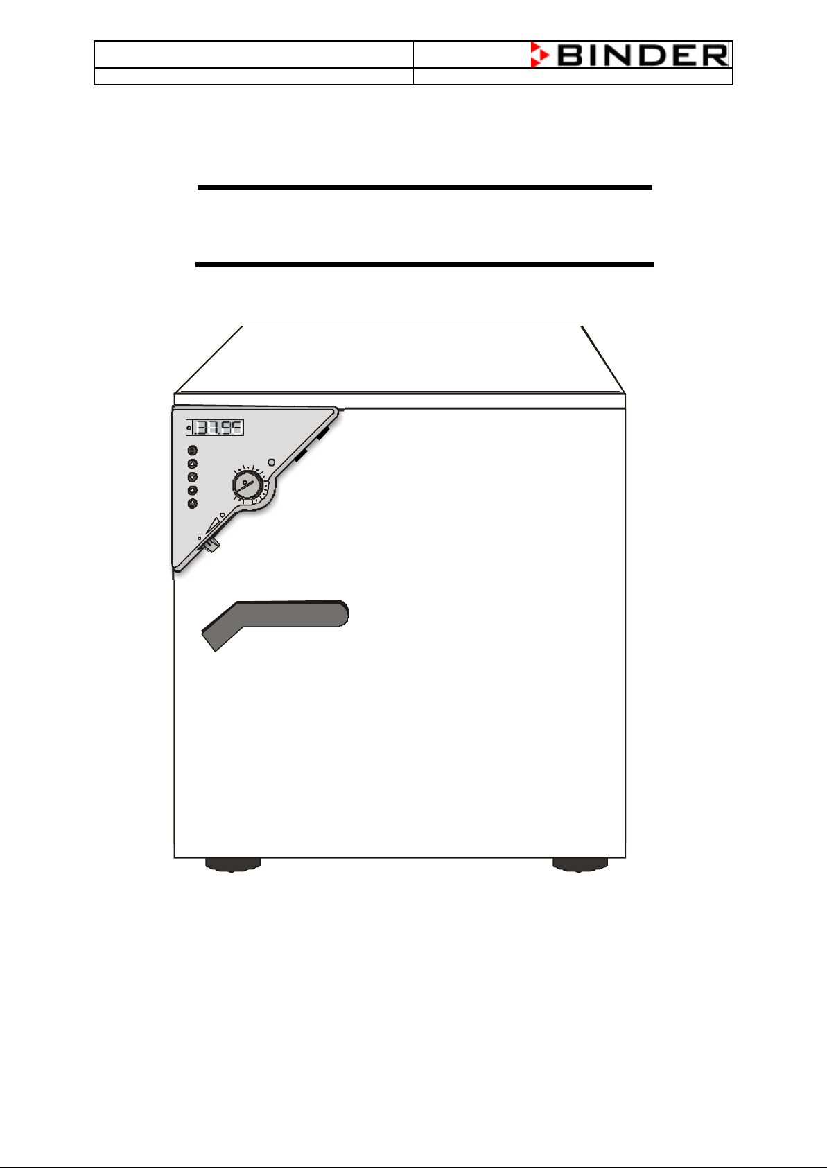
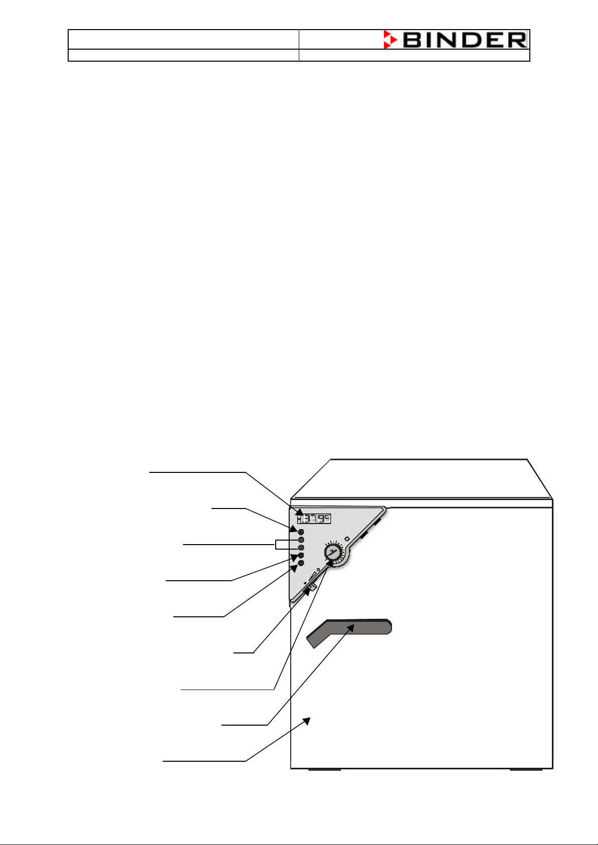
1.4 Description of the Chamber BD, ED and FD
1. Display
2. Required value key
3. Selector keys
4. Timer key
5. Main switch
6. Lever for ventilationslide
7. Safety device
8. Lever door open/close
9. Unit door
Picture 1: Heating Oven with R3-Controller
3
Page 4
BD/ED/FD (E2) Service Manual
Ω
State: 01/2002 Created: 06/2002 / Jochen Tussinger
2 Function
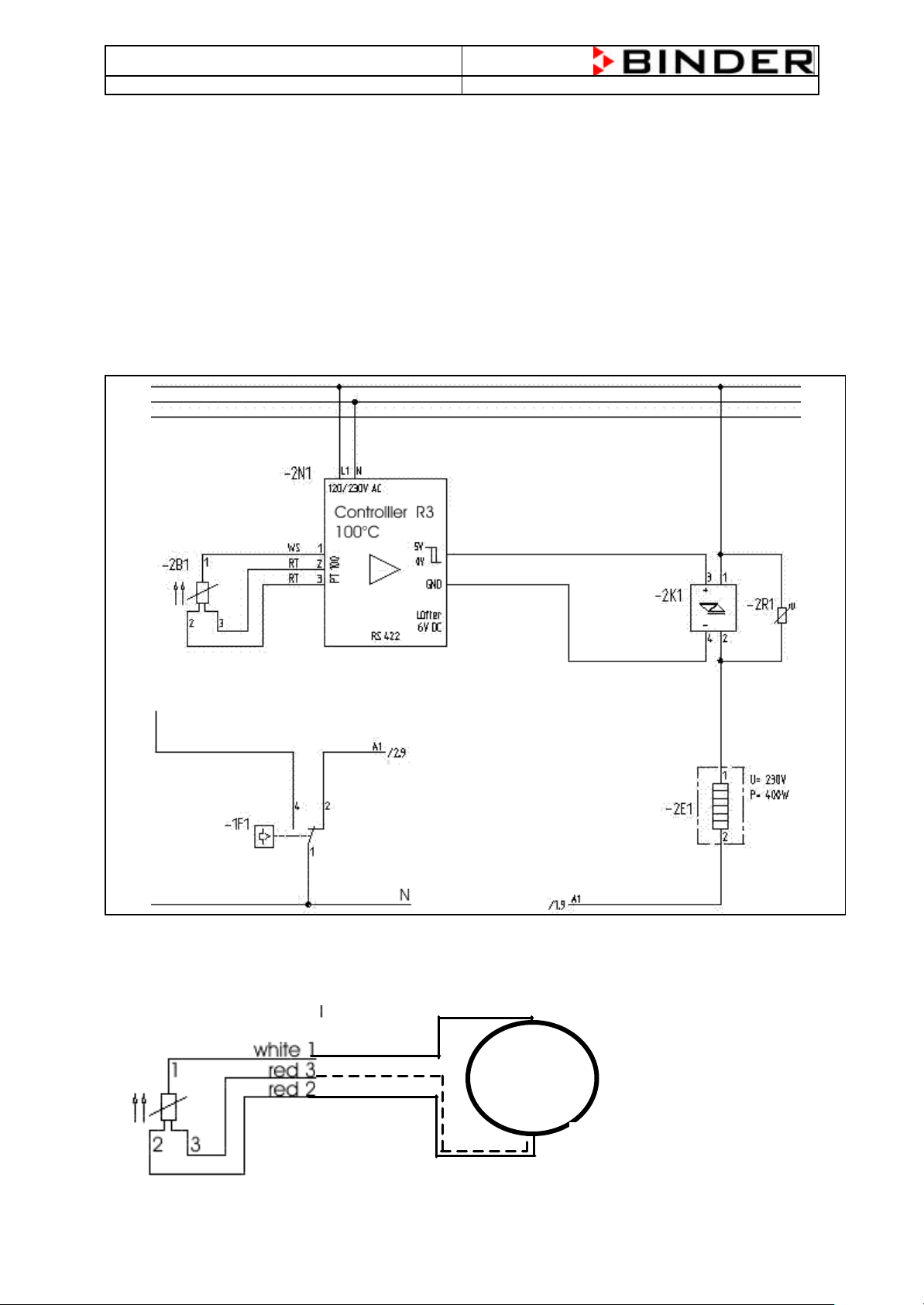
2.1 BD (E2)
The BD (E2) chamber gives the possibility to heat up the chamber to a maximum temperature of 100°C.
The measuring of the temperature will be realized by a PT100 temperature probe which is placed directly
in the inner of the chamber .
The controller R3 measures the resistance of the PT100 temperature probe and compares the incoming
signal with the actual engaged value and decides to give a Signal to activate the heating elements or not.
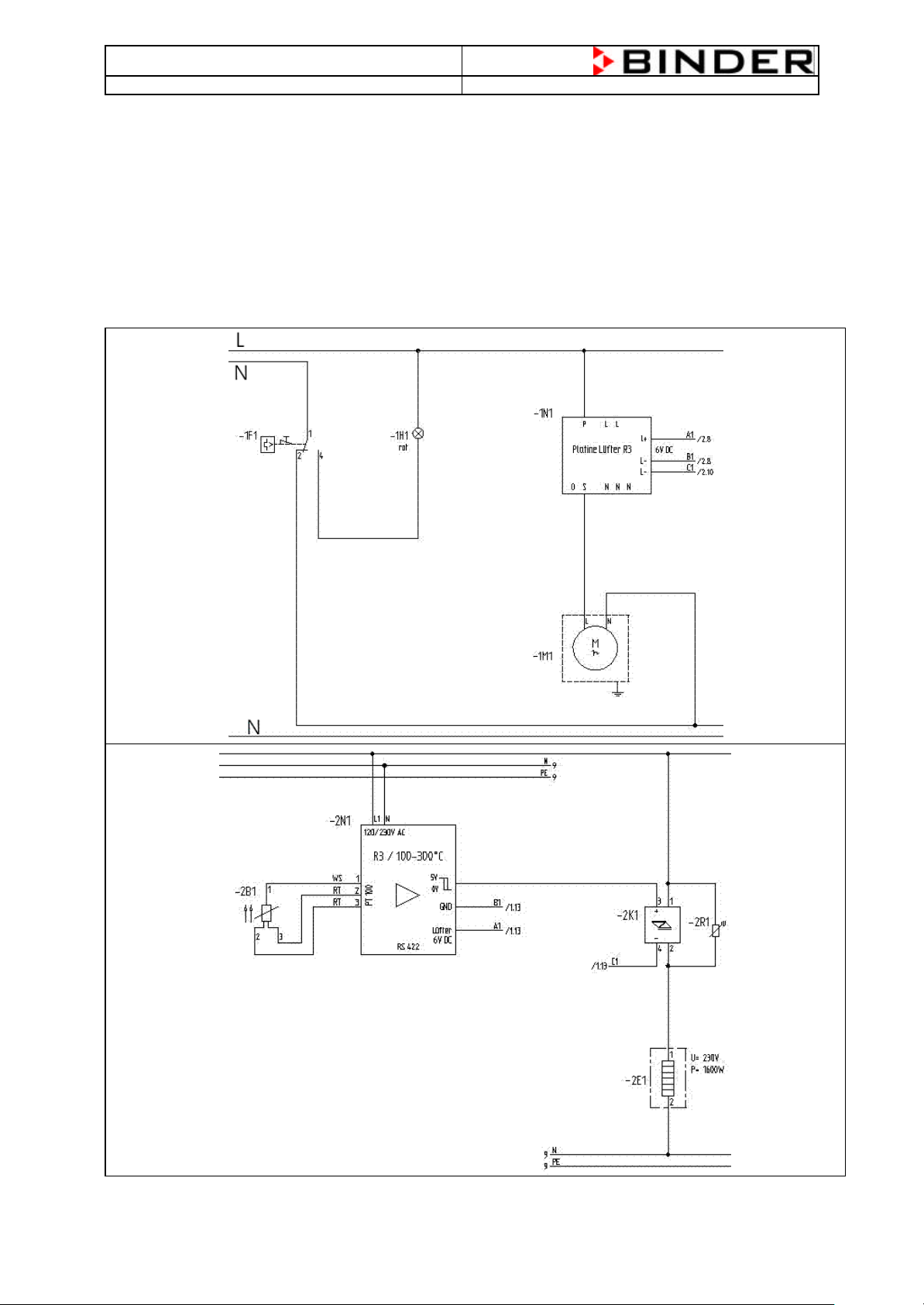
2.2 Flow Chart of the Heating System of a BD (E2) (Standard BD 115 (E2))
PT100 –> Controller R3 à Solid State Relay à Heating Element
The PT100 temperature probe is a resistance-measurement system. This means that the PT100 changes
his resistance at different temperatures. For example: at 37°C, the resistance of the PT100 have to be
114,380 Ω. To measure the resistance, disconnect all three cables from the controller and measure
between the white cable and one of the red cables, don’t measure between both red cables.
Measuring of the PT100 resistance
between the white cable 1 and one of the
two red cables 2 or 3
4
Page 5
BD/ED/FD (E2) Service Manual
Ω
Measuring of the PT100 resistance
State: 01/2002 Created: 06/2002 / Jochen Tussinger
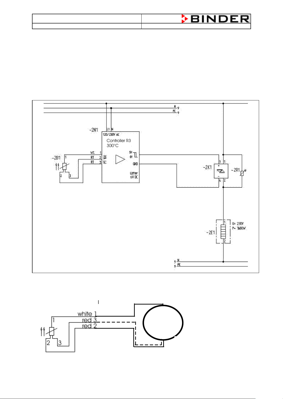
2.3 ED (E2)
The ED (E2) chamber gives the possibility to heat up the chamber to a maximum temperature of 300°C.
The measuring of the temperature will be realized by a PT100 temperature probe which is placed directly
in the inner of the chamber .
The controller R3 measures the resistance of the PT100 temperature probe and compares the incoming
signal with the actual engaged value and decides to give a Signal to activate the heating elements or not.
2.4 Flow Chart of the Heating System of a ED (E2) (Standard ED 115 (E2))
PT100 –> Controller R3 à Solid State Relay à Heating Element
The PT100 temperature probe is a resistance-measurement system. This means that the PT100 changes
his resistance at different temperatures. For example: at 37°C, the resistance of the PT100 have to be
114,380 Ω. To measure the resistance, disconnect all three cables from the controller and measure
between the white cable and one of the red cables, don’t measure between both red cables.
between the white cable 1 and one of the
two red cables 2 or 3
5
Page 6
BD/ED/FD (E2) Service Manual
State: 01/2002 Created: 06/2002 / Jochen Tussinger
2.5 FD (E2)
The FD (E2) chamber gives the possibility to heat up the chamber to a maximum temperature of 300°C.
The measuring of the temperature will be realized by a PT100 temperature probe which is placed directly
in the inner of the chamber .
The controller R3 measures the resistance of the PT100 temperature probe and compares the incoming
signal with the actual engaged value and decides to give a Signal to activate the heating elements or not.
2.6 Flow Chart of the Heating System of a FD (E2) (Standard FD 115 (E2))
PT100 –> Controller R3 à Solid State Relay à Heating Element
6
Page 7
BD/ED/FD (E2) Service Manual
96,086
96,478
96,870
97,262
97,653
98,045
98,436
98,827
99,218
99,609
100,000
100,000
100,391
100,781
101,172
101,562
101,953
102,343
102,733
103,123
103,513
103,902
103,902
104,292
104,681
105,071
105,460
105,849
106,238
106,627
107,016
107,404
107,793
107,793
108,181
108,570
108,958
109,346
109,734
110,122
110,509
110,897
111,284
111,672
111,672
112,059
112,446
112,833
113,220
113,607
113,994
114,380
114,767
115,153
115,539
115,539
115,925
116,311
116,697
117,083
117,469
117,854
118,240
118,625
119,010
119,395
119,395
119,780
120,165
120,550
120,934
121,319
121,703
122,087
122,471
122,855
123,239
123,239
123,623
124,007
124,390
124,774
125,157
125,540
125,923
126,306
126,689
127,072
127,072
127,454
127,837
128,219
128,602
128,984
129,366
129,748
130,130
130,511
130,893
130,893
131,274
131,656
132,037
132,418
132,799
133,180
133,561
133,941
134,322
134,702
134,702
135,083
135,463
135,843
136,223
136,603
136,982
137,362
137,741
138,121
138,500
138,500
138,879
139,258
139,637
140,016
140,395
140,773
141,152
141,530
141,908
142,286
State: 01/2002 Created: 06/2002 / Jochen Tussinger
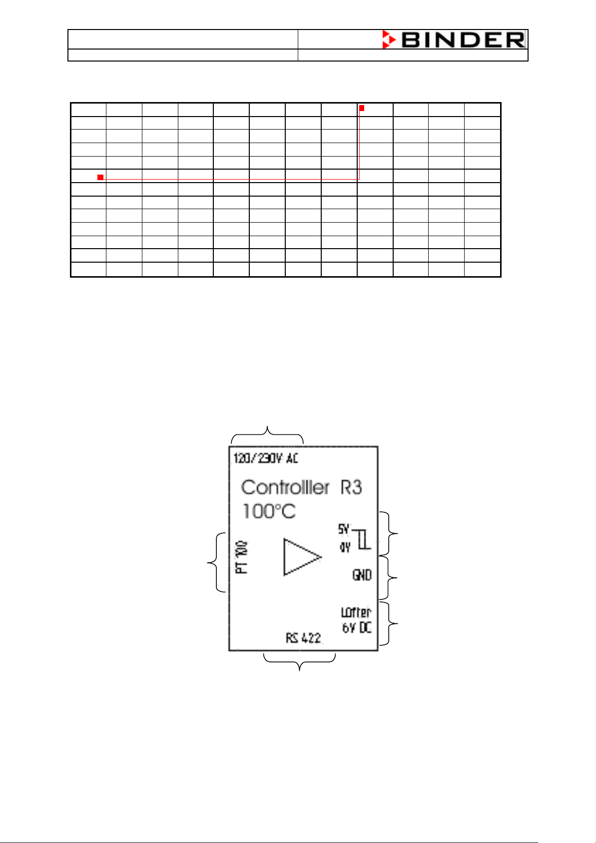
2.7 PT100 Temperature Probe Resistance/Temperature Table
T (°C) 0 1 2 3 4 5 6 7 8 9 10
-10
0
10
20
30
40
50
60
70
80
90
100
For Example: Your resistance measurement system shows you 114,380 Ω this corresponds to 37°C.
2.8 Description of the R3 controller Inputs and Outputs
Power Supply Input
PT100 input
Output Solid State Relay
Ground
Output for fan (only FD)
At BD and ED not in use
RS422 Interface
7
Page 8
BD/ED/FD (E2) Service Manual
State: 01/2002 Created: 06/2002 / Jochen Tussinger
3 Trouble Shooting
3.1 BD Chamber
Fault Description Fault Cause
Not possible to reach the
temperature within the specification
time
The chamber heats over the
temperature setting
The chamber doesn’t heat any time,
the indicator light doesn’t lights up
The chamber doesn’t heat any time,
the indicator light lights up
The glass door of the chamber
doesn’t close.
The chamber doesn’t do anything
The chamber doesn’t do anything,
only the green LED lights
No data transfer to and from the
APT-Com possible. The installation is
correctly. (At BD with Interface)
• The door doesn’t close completely.
• The door sealing is broken or damaged
• The controller need a calibration
• The solid state relay could be defect
• The controller could be defect
• The PT100 could be defect
• The controller need a calibration
• The safety device has switched off the chamber
• Timer off
• The controller is defect
• The solid state relay is defect
• The Heating element(s) is/are defect
• The plastic catcher is defect
• Check if the power supply cable is connected to the mains
• Check if the mains has 115V or 230V voltage
• The chamber is in Stand-by mode
• Wrong chamber address is set at the controller
3.2 ED Chamber
Fault Description Fault Cause
Not possible to reach the
temperature within the specification
time
The chamber heats over the
temperature setting
The chamber doesn’t heat any time,
the indicator light doesn’t lights up
The chamber doesn’t heat any time,
the indicator light lights up
The glass door of the chamber
doesn’t close.
The chamber doesn’t do anything
The chamber doesn’t do anything,
only the green LED lights
No data transfer to and from the
APT-Com possible. The installation is
correctly. (At ED with Interface)
• The door doesn’t close completely.
• The door sealing is broken or damaged
• The controller need a calibration
• The solid state relay could be defect
• The controller could be defect
• The PT100 could be defect
• The controller need a calibration
• The safety device has switched off the chamber
• Timer off
• The controller is defect
• The solid state relay is defect
• The Heating element(s) is/are defect
• The plastic catcher is defect
• Check if the power supply cable is connected to the mains
• Check if the mains has 115V or 230V voltage
• The chamber is in Stand-by mode
• Wrong chamber address is set at the controller
8
Page 9
BD/ED/FD (E2) Service Manual
State: 01/2002 Created: 06/2002 / Jochen Tussinger
3.3 FD Chamber
Fault Description Fault Cause
Not possible to reach the
temperature within the specification
time
The chamber heats over the
temperature setting
The chamber doesn’t heat any time,
the indicator light doesn’t lights up
The chamber doesn’t heat any time,
the indicator light lights up
The glass door of the chamber
doesn’t close.
The chamber doesn’t do anything • Check if the power supply cable is connected to the mains
The chamber doesn’t do anything,
only the green LED lights
No data transfer to and from the
APT-Com possible. The installation is
correctly. (At FD with Interface)
• The door doesn’t close completely.
• The fan doesn’t work
• The door sealing is broken or damaged
• The controller need a calibration
• The solid state relay could be defect
• The controller could be defect
• The PT100 could be defect
• The controller need a calibration
• The safety device has switched off the chamber
• Timer off
• The controller is defect
• The solid state relay is defect
• The Heating element(s) is/are defect
• The plastic catcher is defect
• Check if the mains has 115V or 230V voltage
• The chamber is in Stand-by mode
• Wrong chamber address is set at the controller
3.4 APT-COM at BD, ED and FD
Fault Description Fault Cause
No Function
No data transfer to and from the
APT-Com possible. The installation is
correctly.
• Connection is wrong, check the connection like described in
• Address in the controller is wrong
• Controller is in Stand-By mode
• Wrong chamber address is set at the controller
• The connection cable is broken/defect
• The Switch at the converter is set to DCE (correct = DTE)
• The converter doesn’t get the needed current
Chapter 5 APT-COM Connection
9
Page 10
BD/ED/FD (E2) Service Manual
State: 01/2002 Created: 06/2002 / Jochen Tussinger
4 Most common service works
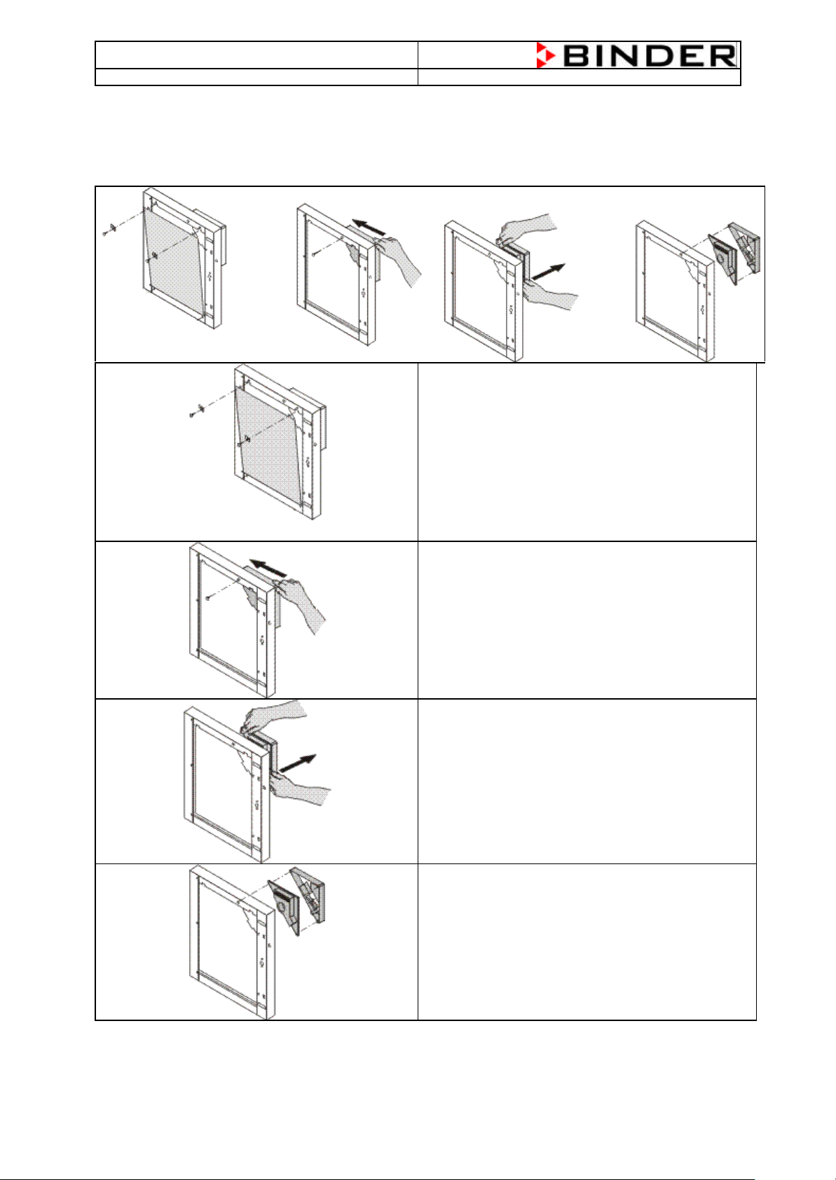
4.1 Changing of the controller R3
You have to open the two screws at the top of the
inner door. After that you can lift out the inner door,
but be careful the temperature safety device is
inside the door.
Now open the screw behind the white plastic cover.
The plastic cover could be broken after that.
Now you have to press like shown picture at the
perpendiculars side to bring out the controller
housing. Please press only in arrow direction.
Now you can take off the complete housing, be
careful, the temperature safety device is connected.
At the rear side of the housing you’ll find two screws,
you have to open them to work on the controller.
To bring back the controller in starting situation,
please fit it together in opposite direction.
10
Page 11
BD/ED/FD (E2) Service Manual
State: 01/2002 Created: 06/2002 / Jochen Tussinger
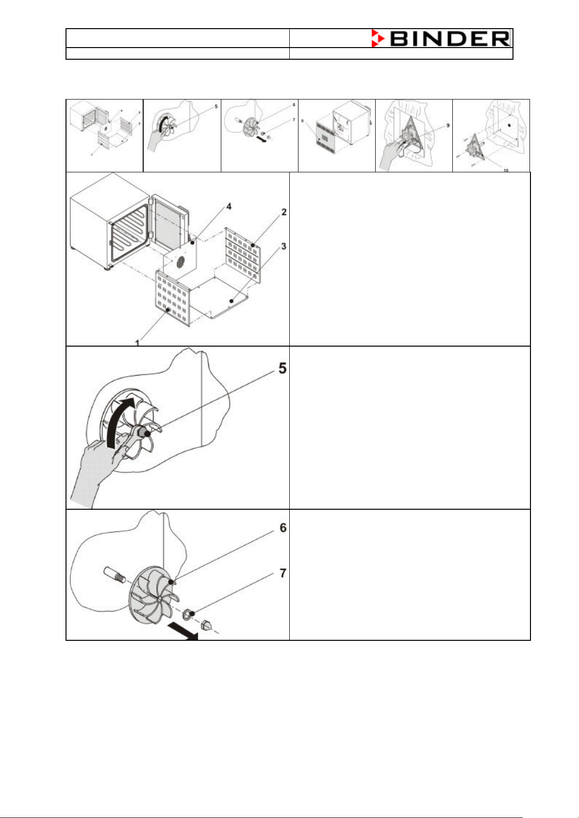
4.2 Changing of the fan at FD (E2) chamber
You have to unscrew the two side-walls (1 + 2), the
bottom (3) and the rear-wall (4) to reach the fanwheel.
The side-walls are screwed at the topside.
Before you could bring out the rear-wall, you have to
remove the PT-100 holder.
After this you can see the heating elements and also
the fan-wheel
Now you have to open the nut at the front of the fanwheel.
Notice: It is a left-thread.
Tool: box wrench size 13
Now it is possible to remove the washer and also the
fan-wheel.
11
Page 12
BD/ED/FD (E2) Service Manual
State: 01/2002 Created: 06/2002 / Jochen Tussinger
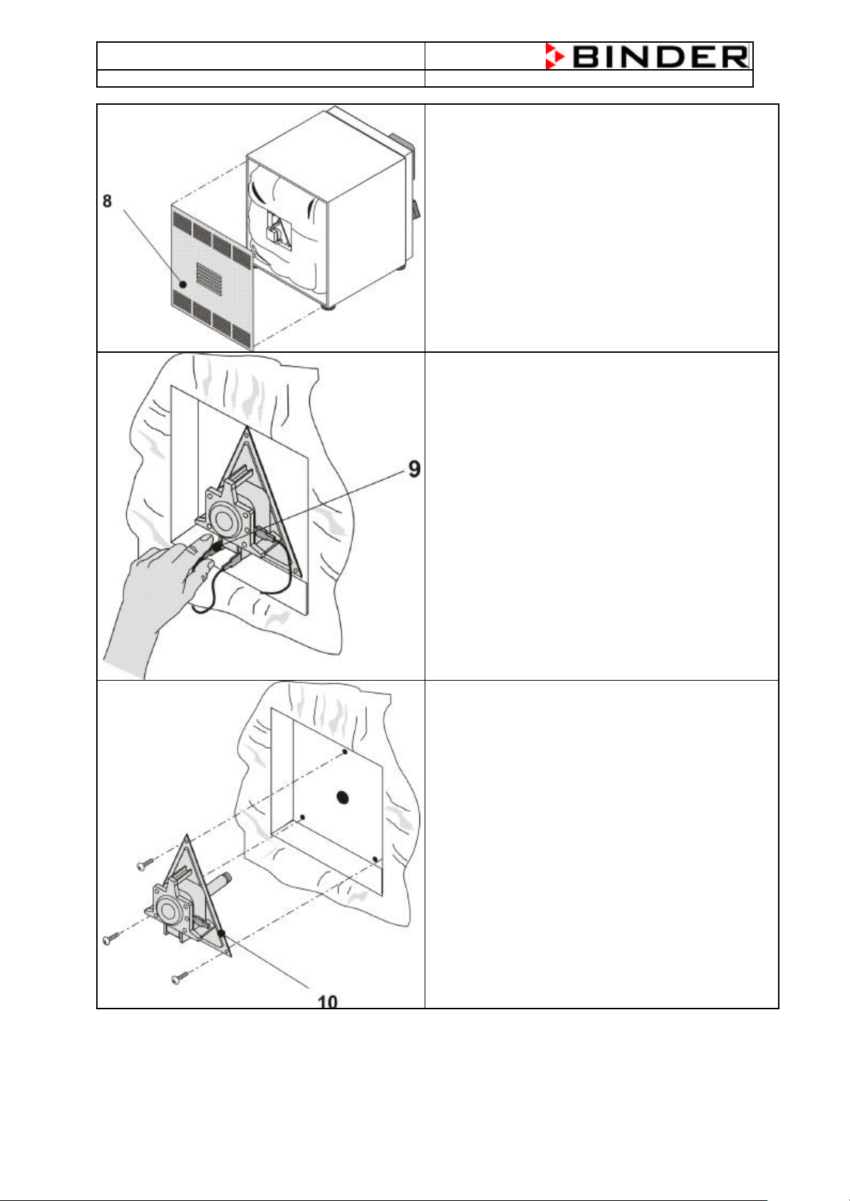
To take out the fan-motor with axis, you have to
remove the rear-wall of the chamber.
Tool: Screwdriver (Phillips-Screw)
Now disconnect the connection-wires at the fan,
if possible mark them for right connection when you
put in the new fan.
To take out the fan-motor with axis, you have to
remove the three Phillips-screw at the triangle.
Now it is possible to take out the complete part.
12
Page 13

BD/ED/FD (E2) Service Manual
State: 01/2002 Created: 06/2002 / Jochen Tussinger
4.3 Calibration Procedure “One Point Calibration”
Press the Buttons and for 5 sec.
simultaneously.
After the 5 sec. you’ll see C211 in the display.
Don’t use this configuration for the One Point
Calibration. You have to use the configuration
C212.
Press the Button to go to configuration C212.
Set the measured value with the Buttons and
like displayed on your reference measurement
system.
13
Page 14

BD/ED/FD (E2) Service Manual
normal
display
X/W
C211
State: 01/2002 Created: 06/2002 / Jochen Tussinger
If you’ve done your settings press the Button to
come back to the Standard Display with the actual
Temperature.
A electronic measuring- and display device for temperature which is traceable to a acknowledged
standards/calibration institution (DKD , PTB for Germany) with valid calibration certificate is
recommended.
Measuring range for incubators at least 20°C to 100°C
Measuring range for warming and drying chambers at least 20°C to 300°C
The sensor probe of the reference instrument placed in the centre of the usable chamber volume should
be connected to the device via a thin cable suitable to be laid over the door sealing without causing any
leakages.
Entering of the higher calibration point:
(One-Point-Calibration))
press and together for 5s
C212 ↔ prevailing entry of the higher calibration point
enter with and the reference value
return with button X/W to normal display
Normally a “One-Point-Calibration” is enough to get a exact regulation of the chamber. If the customer
works at two temperatures which are with a difference of more than 5°C you could do a “Two-PointCalibration” to get a exact regulation.
14
Page 15

BD/ED/FD (E2) Service Manual
State: 01/2002 Created: 06/2002 / Jochen Tussinger
4.4 Change Display from °C (Celsius) to °F (Fahrenheit)
Press the Button for at least 5 seconds
The Display shows „unit“.
Change the setting “C” with the Button into “F”
Attention: The controller changes the value
automatically into °F.
Confirm your new setting by pressing the Button
Press the Button 4 times to go back to the
normal display
Remember:
If you set the chamber to °F, the highest Temperature is 300°F. This corresponds to approx. 148,62°C.
Correlation:
0°C = 31°F
100°C = 212°F
[Value in °F] = 1,81 x [Value in °C] + 31
15
Page 16

BD/ED/FD (E2) Service Manual
State: 01/2002 Created: 06/2002 / Jochen Tussinger
4.5 Activation or deactivation of 0.1 steps at the temperature display.
At the controller R3 it is possible to activate or deactivate the 0.1 step at the display.
At BD chambers which could heat up to 100°C the function is activated.
At ED and FD chambers the function is deactivated. Please note that the 0.1 steps is only displayed up to
99.9 °C, at 100°C the 0.1 step is deactivated automatically.
Step 1 – Deactivation of the Level-Protection
To access the parameter level you have to unlock
the Level-Protection.
You have to press the Button and for
at least 10 seconds simultaneously
Now you’ve reached the menu “Code”
Press the Button to set the value “001” to
“000”
To confirm your setting press the Button
to go back to the normal display
16
Page 17

BD/ED/FD (E2) Service Manual
State: 01/2002 Created: 06/2002 / Jochen Tussinger
Step 2 – Changing of the parameter for the 0.1 degree display
Press the Button for at least 5 seconds
so that “unit” will be displayed
Press the Button for at least 5 seconds again
so that “C111” will be displayed
Press the Button for 1 time to set the “0” to “1”
Confirm your setting by pressing the Button
Press the Button 18 times to go back to
normal display.
The displayed value now is with 0.1 step
Please restore the Level-Protection. If not it is
possible that the parameters could changed. The
chamber doesn’t work correctly.
17
Page 18

BD/ED/FD (E2) Service Manual
State: 01/2002 Created: 06/2002 / Jochen Tussinger
5 BD, ED and FD connected to APT-COM
5.1 Communication Software APT-COM
The units of size 400 and 720 are equipped as standard with an RS422 serial interface (option with size
53, 115 and 240), to which Binder’s
5.2 Settings at the controller R3
The factory setting of the controller is 1. You need this address, that the PC knows with which controller
he has to exchange the data. The function is like a e-Mail System, every one needs a own address to get
the correct data. If you connect more then one chamber, every one needs a own address (1.......30 max).
Following described settings have to be done.
The chamber is switched on and shows the actual
Temperature
Press the Button for 5 seconds at least
Till the display shows “unit”
Press the Button 2 times till the display
shows “Adr” for 1 second
The Display changes now automatically between
„Adr“ and the entered Address.
Now choose the Address with the
Buttons and .
Confirm your setting with the Button till you’re
Back at the Temperature-Display
18
Page 19

BD/ED/FD (E2) Service Manual
State: 01/2002 Created: 06/2002 / Jochen Tussinger
5.3 Connection of one chamber BD, ED or FD
230V
Chamber RS422 Connection Cable Converter with Adapter Cable PC with RS232
If you’ll connect more then one chambers, you need a plug-distributor between the chambers and the
computer.
19
Page 20

Page 21

Page 22

Page 23

Page 24

Page 25

Page 26

Page 27

Page 28

Page 29

Page 30

Page 31

Page 32

Page 33

Page 34

Page 35

Page 36

Page 37

Page 38

Page 39

 Loading...