

Doc. No. 0905BE20500
Rev. B

D:\Binder_E\Manuals_en\COMBIMASS_compact\Titelseite_en.cdr
D:\Binder_E\Manuals_en\Komponenten_alle_Combimass_compact_en.cdr
D:\Binder_E\Montage\Begriffsbestimmung_compact_en.cdr
D:\Binder_E\Montage\B_Maß_nurMuffe_2_en.cdr
D:\Binder_E\Montage\B_Maß_Kugelhahn_1_2_en.cdr
D:\Binder_E\Montage\B_Maß_Kugelhahn_2_2_en.cdr
D:\Binder_E\Montage\Inst_Sensor_compact_en.cdr
D:\Binder_E\Elektronik\Verdrahtung compact Feldgeraet IP und EEx ed_en.cdr
D:\Binder_E\Elektronik\Verdrahtung_Feldgehaeuse_compact_IP_en.cdr
D:\Binder_E\Uebersichtsplaene\Tabelle_Wiring_Combimass_compact_IP_en.cdr
D:\Binder_E\Schaltschrank\Combimass_compact_EEx ia Rittal 400x400_en.cdr
D:\Binder_E\Datenblaetter\fertige Datenblaetter\Seite1_Verdrahtung Compact EEx ia Vers 1 v3_en.cdr
D:\Binder_E\Datenblaetter\fertige Datenblaetter\Seite2_Tabellen Compact EEx ia modular_en.cdr
D:\Binder_E\Error\Fehleranzeige Master_Speisetrenner Combimass CIII_en.cdr
D:\Binder_E\Datenblaetter\Combimass_compact_en.cdr
D:\Binder_E\Montage\Ein_Auslaufstrecke_2004-02-24_combimass_en.cdr

Copyright © BINDER GmbH - Ulm 2005
All rights reserved.
This Assembly and Operating Manual is protected by copyright. No part of this publication may be copied, photocopied, reproduced or translated in any form or processed,
duplicated or distributed electronically without the prior express permission in writing of
BINDER GmbH.
Printed by BINDER GmbH

4
COMBIMASS® compact
IMPRESSUM
____________________________________________
BINDER GmbH
Buchbrunnenweg 18
89081 Ulm, Germany
Tel. +49 731 18998-0
Fax +49 731 18998-88
info@binder-flow.com
www.binder-flow.com
Assembly and Operating Manual
COMBIMASS
®
compact

COMBIMASS® compact
5
Contents
Doc. No.: 0905XE20500
Chapter 1 Safety, General Information 7
SYMBOLS . . . . . . . . . . . . . . . . . . . . . . . . . . . . . . . . . . . . . . . . . . . . . . . . . . . . . . . . . . . . . . . . . . . . . . . . . . . . . 7
SAFETY PRECAUTIONS . . . . . . . . . . . . . . . . . . . . . . . . . . . . . . . . . . . . . . . . . . . . . . . . . . . . . . . . . . . . . . . . . . . 7
Components of the COMBIMASS® compact unit. . . . . . . . . . . . . . . . . . . . . . . . . . . . . . . . . . . . . . . . . . . . . . . 8
GENERAL INFORMATION . . . . . . . . . . . . . . . . . . . . . . . . . . . . . . . . . . . . . . . . . . . . . . . . . . . . . . . . . . . . . . . . . 9
Functional Description . . . . . . . . . . . . . . . . . . . . . . . . . . . . . . . . . . . . . . . . . . . . . . . . . . . . . . . . . . . . . . . . 9
Important Points . . . . . . . . . . . . . . . . . . . . . . . . . . . . . . . . . . . . . . . . . . . . . . . . . . . . . . . . . . . . . . . . . . . . . 9
Chapter 2 Installation 11
Preparation for installation . . . . . . . . . . . . . . . . . . . . . . . . . . . . . . . . . . . . . . . . . . . . . . . . . . . . . . . . . . . . . . . 11
Receipt of goods: . . . . . . . . . . . . . . . . . . . . . . . . . . . . . . . . . . . . . . . . . . . . . . . . . . . . . . . . . . . . . . . 11
Complaints . . . . . . . . . . . . . . . . . . . . . . . . . . . . . . . . . . . . . . . . . . . . . . . . . . . . . . . . . . . . . . . . . . . . 11
Calibration note . . . . . . . . . . . . . . . . . . . . . . . . . . . . . . . . . . . . . . . . . . . . . . . . . . . . . . . . . . . . . . . . 11
ESD (damage caused by electrostatic discharges) . . . . . . . . . . . . . . . . . . . . . . . . . . . . . . . . . . . . . . . . 11
Installation of the sensor . . . . . . . . . . . . . . . . . . . . . . . . . . . . . . . . . . . . . . . . . . . . . . . . . . . . . . . . . . . . . . . . . 12
Definition . . . . . . . . . . . . . . . . . . . . . . . . . . . . . . . . . . . . . . . . . . . . . . . . . . . . . . . . . . . . . . . . . . . . . . . . . 12
Positioning the sensor rod, determining dimension B . . . . . . . . . . . . . . . . . . . . . . . . . . . . . . . . . . . . . . . . . . . 13
Determining dimension B (without a feed unit) . . . . . . . . . . . . . . . . . . . . . . . . . . . . . . . . . . . . . . . . . 13
Determining the B dimension (feed unit, welded sleeve with external thread) . . . . . . . . . . . . . . . . . . 14
Determining the B dimension (feed unit, welded sleeve with internal thread) . . . . . . . . . . . . . . . . . . . 15
Positioning the sensor rod . . . . . . . . . . . . . . . . . . . . . . . . . . . . . . . . . . . . . . . . . . . . . . . . . . . . . . . . . . . . . . . . 16
(When sensor rod is longer than the internal diameter of the pipe) . . . . . . . . . . . . . . . . . . . . . . . . . . 16
(When sensor rod is shorter than the internal diameter of the pipe) . . . . . . . . . . . . . . . . . . . . . . . . . . 16
Diagram: Positioning the sensor rod . . . . . . . . . . . . . . . . . . . . . . . . . . . . . . . . . . . . . . . . . . . . . . . . . . . . . 17
Wiring of the sensor electronic for field unit . . . . . . . . . . . . . . . . . . . . . . . . . . . . . . . . . . . . . . . . . . . . . . . . . . 18
Protection class: IP65und EEx [ed]
Diagram: Wiring of the sensor for field unit . . . . . . . . . . . . . . . . . . . . . . . . . . . . . . . . . . . . . . . . . . . . . . . 18
Wiring of the sensor electronic with field housing (optional) . . . . . . . . . . . . . . . . . . . . . . . . . . . . . . . . . . . . . . 19
Protection class: Sensor IP and EEx [ed], field housing IP65
Diagram: Wiring of the sensor electronic with field housing . . . . . . . . . . . . . . . . . . . . . . . . . . . . . . . . . . . 19
Table: Wiring of the sensor electronic with field housing . . . . . . . . . . . . . . . . . . . . . . . . . . . . . . . . . . . . . . 20
Wiring of the sensor electronic with supply isolator and field housing (optional) . . . . . . . . . . . . . . . . . . . . . . . 21
Protection class: Sensor EEx [ia], field housing IP55
Diagram: Wiring of the sensor electronic with supply isolator and field housing . . . . . . . . . . . . . . . . . . . . 21
Table: Wiring of the sensor electronic with supply isolator and field housing . . . . . . . . . . . . . . . . . . . . . . 22
Wiring of the sensor electronic with supply isolator in modular form (optional) . . . . . . . . . . . . . . . . . . . . . . . . 23
Protection class: Sensor EEx [ia]
Table: Wiring of the sensor electronic with supply isolator in modular form . . . . . . . . . . . . . . . . . . . . . . . . 24
Error detection: Wiring error in the sensor electronic with supply isolator . . . . . . . . . . . . . . . . . . . . . . . . . . . . 25
25
Chapter 3 Appendix 27
Appendix: Specification electronic . . . . . . . . . . . . . . . . . . . . . . . . . . . . . . . . . . . . . . . . . . . . . . . . . . . . . . . . . . 27
Appendix: Specification sensor . . . . . . . . . . . . . . . . . . . . . . . . . . . . . . . . . . . . . . . . . . . . . . . . . . . . . . . . . . . . 28
Appendix: Specification Massflow Meter . . . . . . . . . . . . . . . . . . . . . . . . . . . . . . . . . . . . . . . . . . . . . . . . . . . . . 29
Appendix: Dimensional drawing of COMBIMASS® compact components . . . . . . . . . . . . . . . . . . . . . . . . . . . . 30
Appendix: Inlet and outlet straight pipe runs . . . . . . . . . . . . . . . . . . . . . . . . . . . . . . . . . . . . . . . . . . . . . . . . . . 31
Option: Operating the Graphic-Display Combimass CIII . . . . . . . . . . . . . . . . . . . . . . . . . . . . . . . . . . . . . . . . . . 33
In general: . . . . . . . . . . . . . . . . . . . . . . . . . . . . . . . . . . . . . . . . . . . . . . . . . . . . . . . . . . . . . . . . . . . . . . . . 33
Entering the menu: . . . . . . . . . . . . . . . . . . . . . . . . . . . . . . . . . . . . . . . . . . . . . . . . . . . . . . . . . . . . . . . . . . 34
Setting the inner diameter of the pipe: . . . . . . . . . . . . . . . . . . . . . . . . . . . . . . . . . . . . . . . . . . . . . . . . . . . 35
The summation: . . . . . . . . . . . . . . . . . . . . . . . . . . . . . . . . . . . . . . . . . . . . . . . . . . . . . . . . . . . . . . . . . . . . 37
The pulse: . . . . . . . . . . . . . . . . . . . . . . . . . . . . . . . . . . . . . . . . . . . . . . . . . . . . . . . . . . . . . . . . . . . . . . . . . 39
Analog-Output: . . . . . . . . . . . . . . . . . . . . . . . . . . . . . . . . . . . . . . . . . . . . . . . . . . . . . . . . . . . . . . . . . . . . 40
The correction menu: . . . . . . . . . . . . . . . . . . . . . . . . . . . . . . . . . . . . . . . . . . . . . . . . . . . . . . . . . . . . . . . . 41
The info menu: . . . . . . . . . . . . . . . . . . . . . . . . . . . . . . . . . . . . . . . . . . . . . . . . . . . . . . . . . . . . . . . . . . . . . 42
Structure of the menu: . . . . . . . . . . . . . . . . . . . . . . . . . . . . . . . . . . . . . . . . . . . . . . . . . . . . . . . . . . . . . . . 43

6
COMBIMASS® compact
Contents
Doc. No.: 0905XE20500
Option: Operating Internal Display Combimass CIII . . . . . . . . . . . . . . . . . . . . . . . . . . . . . . . . . . . . . . . . . . . . . 44
Operating with a magnet in general: . . . . . . . . . . . . . . . . . . . . . . . . . . . . . . . . . . . . . . . . . . . . . . . . . . . . 44
Entering the menu: . . . . . . . . . . . . . . . . . . . . . . . . . . . . . . . . . . . . . . . . . . . . . . . . . . . . . . . . . . . . . . . . . . 44
Exiting a menu: . . . . . . . . . . . . . . . . . . . . . . . . . . . . . . . . . . . . . . . . . . . . . . . . . . . . . . . . . . . . . . . . . . . . . 45
Changing a value: . . . . . . . . . . . . . . . . . . . . . . . . . . . . . . . . . . . . . . . . . . . . . . . . . . . . . . . . . . . . . . . . . . . 45
Changing the diameter: . . . . . . . . . . . . . . . . . . . . . . . . . . . . . . . . . . . . . . . . . . . . . . . . . . . . . . . . . . . . . . 46
The summation: . . . . . . . . . . . . . . . . . . . . . . . . . . . . . . . . . . . . . . . . . . . . . . . . . . . . . . . . . . . . . . . . . . . . 46
The pulse: . . . . . . . . . . . . . . . . . . . . . . . . . . . . . . . . . . . . . . . . . . . . . . . . . . . . . . . . . . . . . . . . . . . . . . . . . 48
The analog output: . . . . . . . . . . . . . . . . . . . . . . . . . . . . . . . . . . . . . . . . . . . . . . . . . . . . . . . . . . . . . . . . . . 49
The correction menu: . . . . . . . . . . . . . . . . . . . . . . . . . . . . . . . . . . . . . . . . . . . . . . . . . . . . . . . . . . . . . . . . 49
Structure of the menu: . . . . . . . . . . . . . . . . . . . . . . . . . . . . . . . . . . . . . . . . . . . . . . . . . . . . . . . . . . . . . . . 50
Appendix: Declaration on the Contamination . . . . . . . . . . . . . . . . . . . . . . . . . . . . . . . . . . . . . . . . . . . . . . . . . 51
Chapter 4 Index 53
COMBIMASS® compact
Doc. No.: 0905EE20500
7
Chapter 1 Safety, General Information
Chapter 1 Safety, General Information
SYMBOLS
This Assembly and Operating Manual highlights safety information as follows:
The danger information directs the attention of the operator towards a special procedure or practice which
can cause serious injury to persons if carried out incorrectly.
The information warning the user against certain procedures indicates that failure to observe this information can cause serious damage to the equipment.
The notes highlight important information in the text.
SAFETY PRECAUTIONS
This document describes general safety precautions for handling units of the COMBIMASS® series with
regard to installation, operation and maintenance.
This document is intended as additional information and not as a substitute for the specific safety regulations of the country of destination. Compliance with the safety regulations is the responsibility of the customer, the user and/or the expert personnel involved.
Before using COMBIMASS
®
products, please observe the relevant documentation. Please also note the
safety information given in this chapter and in the operating manuals.
Before using the unit, the user should read this operating manual carefully. BINDER GmbH will accept no
responsibility for complete or partial failure to comply with the information included in the manual, incorrect use by untrained personnel, unauthorized manipulation and any use which does not comply with the
national regulations. During installation, setup and maintenance work, all instructions included in this operating manual must be complied with.
The measuring system with a stainless steel sensor tube and a stainless steel sensor (standard version) is
suitable for the mass flow measurement of gases.
It is not suitable for measuring flowing liquids.
Please note: The maintenance measures described in this manual must be carried out by experpert
personnel only.
DANGER
ATT EN TI ON !
NOTE
DANGER
COMBIMASS® compact
Doc. No.: 0905EE20500 8
Chapter 1 Safety, General Information
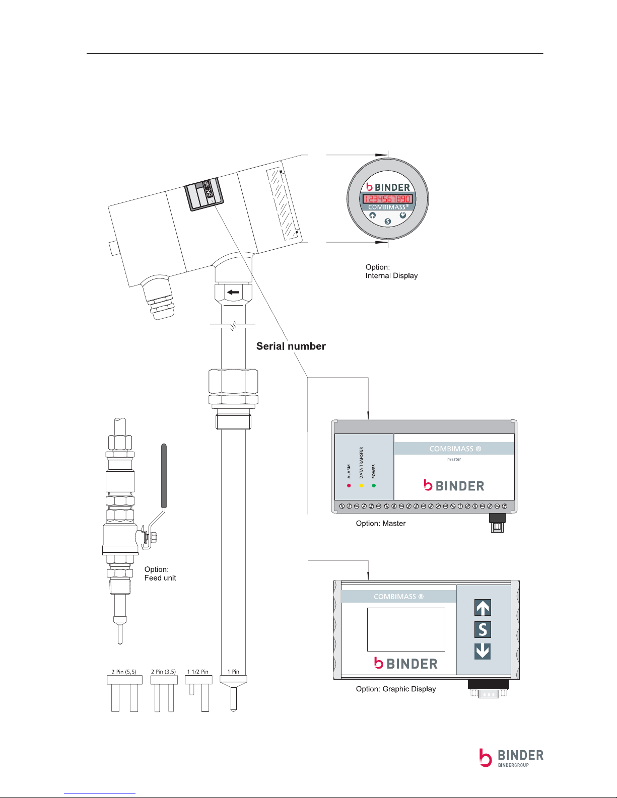
Components of the COMBIMASS® compact unit.
The COMBIMASS® compact system consists of the following components:

COMBIMASS® compact
Doc. No.: 0905EE20500
9
Chapter 1 Safety, General Information
GENERAL INFORMATION
The following description in the operating manual provides information on installation, initial operation,
control of the electronics, and the gas flow measuring system.
Only careful observance of the operating manual can ensure perfect functioning of the system and prevent
exposing the expert personnel to unnecessary danger. For the specifications of your measuring system,
please see the calibration specifications enclosed in duplicate.
Functional Description
The COMBIMASS® compact series of gas mass flow meters are field transmitters for flow rate measurement
■ The flow meters are especially designed for high temperature and high operating pressure process
applications of up to 1100°C and 100 bars.
■ Optionally, the units are available in explosion-proof versions for Zone 1 or Zone 0.
■ The flow transmitters apply thermal dispersion technology in order to measure directly the normal vo-
lumetric or gas mass flow, regardless of the operating pressure and temperature of the medium.
■ For the purposes of practical operation the transmitter electronics features temperature compensation
and the possibility to select different measuring modes (choice of constant current or constant temperature principle).
■ For transmission of the flow signal an isolated 4-20 mA analog output as well as a field selectable pulse
output is available.
■ For intrinsically safe operation a dedicated process interface module has been developed for the power
supply of the flow transmitter. The signal output is taken off via an I/O module that is installed after
the process interface module.
■ Both the circuit boards of the process interface module and the I/O module are mounted in top hat rail
housing for easy assembly in the field cabinet.
■ Also an optionally available graphic display may be installed.
■ The flow transmitter can be combined with a wide range of different sensors of the COMBIMASS@
family and assembled individually according to the specific application.
■ Each flow meter will be tested prior to shipment and calibrated at our CAMASS@ calibration centre
under actual operating conditions.
Technical specification see page 27
Important Points
1. The electronic enclosure and the electronics (master or slave) must both have the same serial number
as each measurement system is calibrated individually depending on the measurement point used (for
the serial number please see page 8).
2. The actual internal diameter of the piping should be measured in order to ensure that it corresponds
with the diameter given in the calibration specification.
3. For flow rate measurement of wet process gases with condensation of water (eg. digester gas), the
sensors have to be installed from the side. It is recommended to clean the sensor every 3-6 month, in
particular if no filter is installed upstream of the sensor.
4. If the sensor tube is twisted with regard to the connecting head during assembly, it must be newly
sealed in.
5. Always transport or dispatch the sensor in the protective tube.
NOTE
ATT EN TI ON !

COMBIMASS® compact
Doc. No.: 0905EE20500 10
Chapter 1 Safety, General Information

COMBIMASS® compact
Doc. No.: 0905ME20500
11
Chapter 2 Installation
Chapter 2 Installation
Preparation for installation
Receipt of goods:
■ Carefully unpack the measuring system.
■ Check that all items were correctly and completely delivered in accordance with the delivery note.
■ Check the measuring system for damage before you install it.
If you have observed all the points, then continue with the installation of the sensor.
■ If there are any reasons for complaint, please contact customer service.
Complaints
Please contact first the responsible service technician. If you don’t know the telephone number of your
service technician please contact our headquarter in
Ulm/Germany. We will be pleased to help you.
Please return a damaged or incorrectly supplied system to the following address:
BINDER GmbH
Buchbrunnenweg 18
D-89091 Ulm
Tel. : +49 (0)731 189 98-0
Fax : +49 (0)731 189 98-88
■ Please include a note on the covering letter such as, e.g. "System defective, device has not been used"
or "Incorrect supply, device has not been used". In these cases, no clearance certificate is required
(see page 51).
Calibration note
The mass flow measuring system is calibrated to suit your application. All relevant information regarding
the calibration of your system can be obtained from the calibration data sheet.
No further settings or adjustments are required. The system is ready for operation.
ESD (damage caused by electrostatic discharges)
The electronics can be damaged by electrostatic discharge (ESD). Carry out repairs, modifications and tests
at an ESD workplace.
If such a workplace is not available, wear an antistatic wrist strap or touch a suitably conductive, earthed
body.
Damage which arises as a result of incorrect handling cannot be accepted under the terms of the guarantee.
NOTE
ATT EN TI ON !
COMBIMASS® compact
Doc. No.: 0905ME20500 12
Chapter 2 Installation
Installation of the sensor
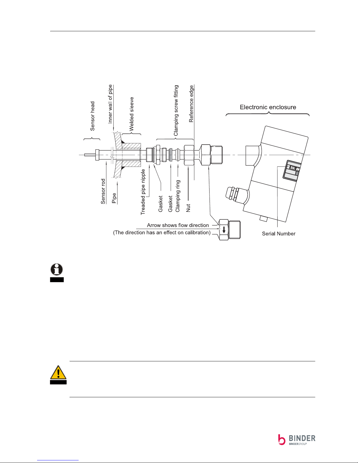
Definition
The following points must be observed for optimum operation in service:
■ The ideal conditions are an inflow length of 20 x pipe diameter and an outflow length of 10 x pipe
diameter.
■ In cases where the installation situation deviates from this, an adaptation must be made.
■ The sensor must be installed so that the installation position corresponds to the calibration position,
see data sheet (vertical/horizontal pipe etc.).
■ The angle of incidence to the sensor must be 90°.
■ The sensor is provided with flats situated between the process connection and the connecting
head for the purpose of alignment.
■ Align these flats parallel to the pipe axis (+/- 3°).
■ The flow direction is marked on the flats in the form of an arrow.
■ The actual internal diameter should be measured and should correspond to the diameter specified on
the calibration data sheet.
■ The sensor head must be located in the centre of the pipe. To position the sensor head, proceed by
following one of the two methods given in the instructions below.
The clamping ring connection is to be inserted into the process connection using the prescribed sealing
material.
Otherwise, aggressive gases could escape. The consequences would be injuries to the skin or respiratory
tracts and corrosion of the surrounding materials.
In the case of combustible gases, a leak will give rise to a fire or explosion hazard.
NOTE
DANGER
COMBIMASS® compact
Doc. No.: 0905ME20500
13
Chapter 2 Installation
Positioning the sensor rod, determining dimension B
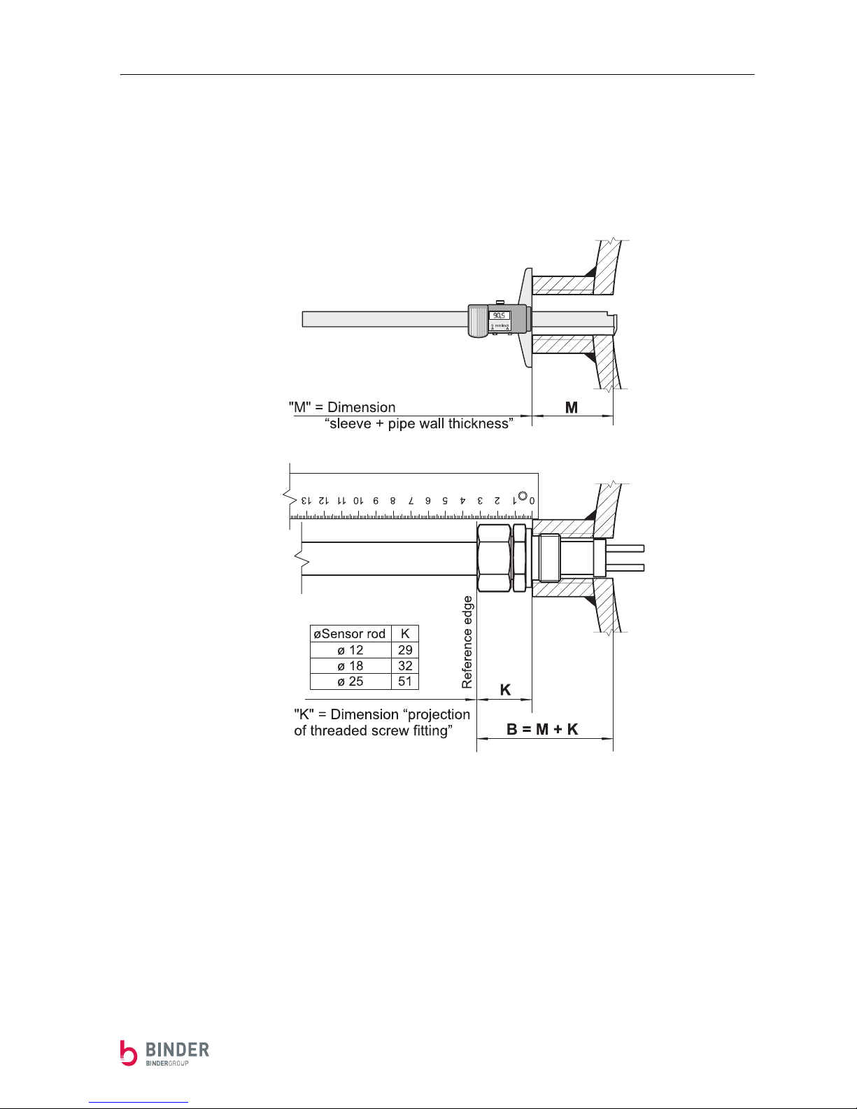
Determining dimension B (without a feed unit)
Before installing the sensor, you should measure the length of the welded sleeve up to the inner wall of
the pipe (dimension "M" as on the left of the following diagram) in order to determine dimension "B".
Screw the threaded pipe nipple into the welded sleeve. Please use sealing material according to the specifications.
Screw the nut with the pressing ring and the cutting ring onto the threaded pipe nipple in such a way that
the sensor rod can still move.
Measure dimension "K" = reference edge up to sleeve (see on the left of above diagram).
Add dimensions "K" and "M" to obtain dimension "B".
COMBIMASS® compact
Doc. No.: 0905ME20500 14
Chapter 2 Installation
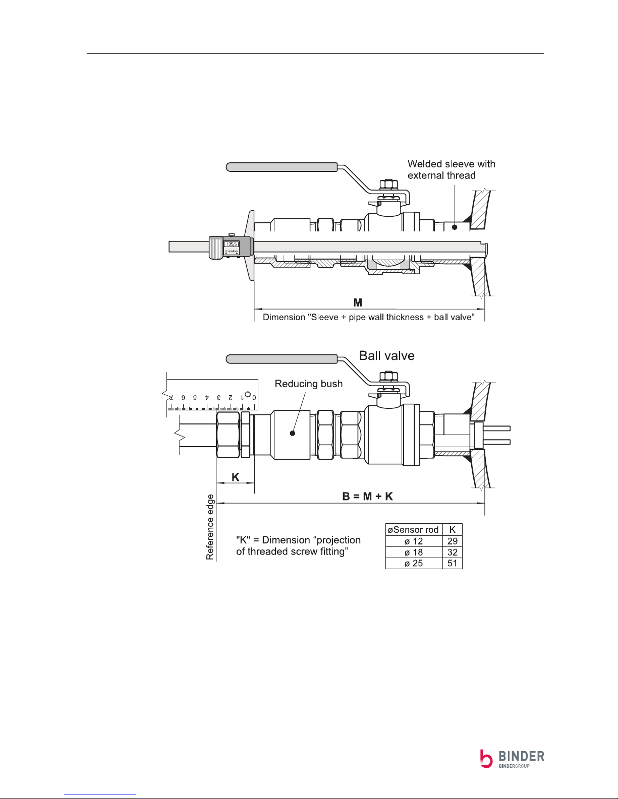
Determining the B dimension (feed unit, welded sleeve with external
thread)
First, with the feed unit installed, measure the whole length from the inner wall of the pipe to the end of
the reducing bush (dimension "M" as on the left of the following diagram) in order to determine dimension "B".
Screw the threaded pipe nipple of the clamping screw fitting into the reducing bush. Please use sealing
material according to the specifications.
Screw the nut with the pressing ring and the cutting ring onto the threaded pipe nipple in such a way that
the sensor rod can still move.
Measure dimension "K" = reference edge up to reducing bush (see on the left of above diagram).
Add dimensions "K" and "M" to obtain dimension "B".
COMBIMASS® compact
Doc. No.: 0905ME20500
15
Chapter 2 Installation
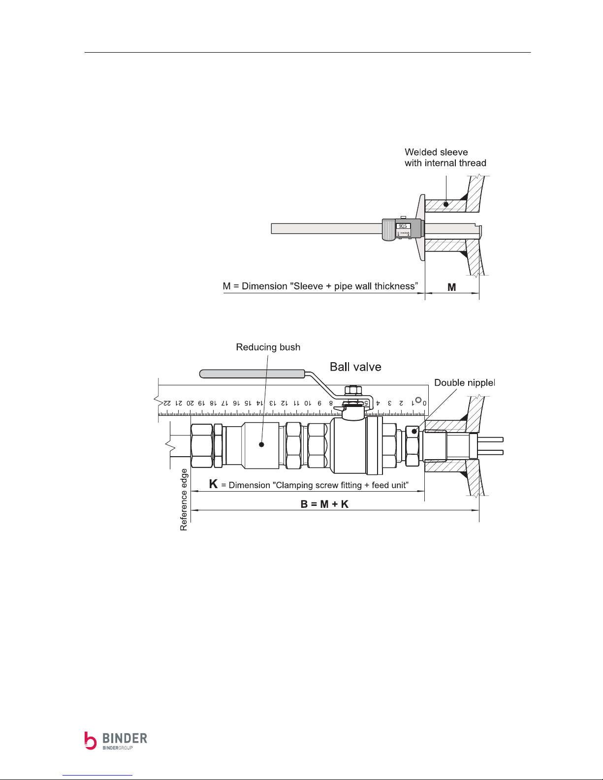
Determining the B dimension (feed unit, welded sleeve with internal
thread)
Before installing the feed unit, you should measure the length of the welded sleeve up to the inner wall
of the pipe (dimension "M" as on the left of the following diagram) in order to determine dimension "B".
Install the feed unit. Please use sealing material according to the specifications. Screw the threaded pipe
nipple of the clamping screw fitting into the reducing bush. Screw the nut with the pressing ring and the
cutting ring onto the threaded pipe nipple in such a way that the sensor rod can still move.
Measure dimension "K" = reference edge up to the welded sleeve (see on left of above diagram).
Add dimensions "K" and "M" to obtain dimension "B".

COMBIMASS® compact
Doc. No.: 0905ME20500 16
Chapter 2 Installation
Positioning the sensor rod
(When sensor rod is longer than the internal diameter of the pipe)
The sensor head must be located in the centre of the pipe (see Fig. B of the following diagram)
The simplest way to guarantee this is to assemble the 3/4" thread or the flange, and then push the sensor
into the pipe up to the stop. Then, pull the sensor back by exactly one half of the nominal diameter of the
pipe (minus 6mm) and now fix it in position by means of the cutting ring connection (max. 1¼ turns).
Where a stainless steel cutting ring is used, the sensor can be positioned only once!
The sensor rod must be fixed securely. Where the pipe is subjected to high pressure, there is a risk of the
sensor being ejected as far as the clamping ring in the manner of a projectile and thereby endangering
personnel.
(When sensor rod is shorter than the internal diameter of the pipe)
In the case of larger pipe diameters, proceed as shown in Fig. A of the following diagram.
The sensor is pulled back to the reducing pipe nipple. Mark the sensor rod at a distance of
"DI/2 + B - N"
DI/2 = half internal diameter of pipe
B = Inner wall of pipe up to reference edge
Look up dimension “B“ corresponding to the variant of mounting in the instructions on
page 13, page 14, or page 15.
N = KL + S - 6 mm KL = Screw fitting, S = Sensor head
Please choose dimension “N“ from the table on page 17.
Push the sensor into the clamped connection up to this mark (see Fig. B of the following diagram) and fix
it in position by means of the cutting ring connection.
Where a stainless steel cutting ring is used, the sensor can be positioned only once!
The sensor rod must be fixed securely. Where the pipe is subjected to high pressure, there is a risk of the
sensor being ejected as far as the clamping ring in the manner of a projectile and thereby endangering
personnel.
DANGER
DANGER
 Loading...