

Page 1

BiPAC 7404V(G)OX/V(G)PX
3G/VoIP/(802.11g)
ADSL2+ (VPN) Firewall Router
User Manual
Version release: 1.10(5.53.s6.b1.dg8)
Last Revised Date: 03-08-2010
Page 2

Table of Contents
Chapter 1: Introduction ............................................................................................ 1
Chapter 2: Installing the Router ............................................................................... 5
Package Contents .............................................................................................. 5
The Front LEDs............................................................................................. 6
The Rear Ports.............................................................................................. 7
Cabling ............................................................................................................... 8
Chapter 3: Basic Installation .................................................................................... 9
Connecting Your Router
Network Configuration.......................................................................................11
Configuring PC in windows 7 .......................................................................11
Configuring PC in Windows Vista
Configuring PC in Windows XP
Configuring PC in Windows 2000
Configuring PC in Windows 95/98/Me
Configuring PC in Windows NT4.0
Factory Default Settings ................................................................................... 19
Information from your ISP................................................................................. 20
Configuring with your Web Browser ................................................................. 21
Chapter 4: Configuration........................................................................................ 22
Status ............................................................................................................... 23
ADSL Status................................................................................................ 23
3G Status .................................................................................................... 23
EWAN Status .............................................................................................. 24
iBurst Status................................................................................................ 25
ARP Table ................................................................................................... 25
DHCP Table ................................................................................................ 26
Routing Table
NAT Sessions.............................................................................................. 29
UPnP Portmap ............................................................................................ 29
PPTP Status................................................................................................ 30
IPSec Status ............................................................................................... 31
L2TP Status ................................................................................................ 31
VoIP Status.................................................................................................. 32
VoIP Call Log............................................................................................... 32
Event Log.................................................................................................... 33
Error Log ..................................................................................................... 34
Diagnostic ................................................................................................... 34
Quick Start
Configuration .................................................................................................... 40
LAN - Local Area Network........................................................................... 41
........................................................................................................
Bridge Interface ..................................................................................... 41
Ethernet ................................................................................................. 42
IP Alias................................................................................................... 42
Ethernet Client Filter .............................................................................. 43
..............................................................................................
...................................................................................
...............................................................
...................................................................
...............................................................
........................................................
..............................................................
10
13
15
16
17
18
28
35
Page 3

Wireless................................................................................................. 45
Wireless Security................................................................................... 47
Wireless Client / MAC Address Filter..................................................... 50
WPS ...................................................................................................... 51
Port Setting............................................................................................ 60
DHCP Server ......................................................................................... 61
WAN - Wide Area Network .......................................................................... 62
WAN Interface........................................................................................ 62
WAN Profile ........................................................................................... 65
ADSL Mode ........................................................................................... 81
System ........................................................................................................ 82
Time Zone.............................................................................................. 82
Remote Access...................................................................................... 83
Firmware Upgrade................................................................................. 83
Backup / Restore ................................................................................... 84
Restart Router ....................................................................................... 85
User Management ................................................................................. 86
Mail Alert................................................................................................ 88
Firewall and Access Control........................................................................ 90
General Settings.................................................................................... 91
Packet Filter........................................................................................... 92
Intrusion Detection................................................................................. 99
URL Filter............................................................................................. 102
IM / P2P Blocking ................................................................................ 105
Firewall Log ......................................................................................... 106
VPN - Virtual Private Networks ................................................................. 107
PPTP (Point-to-Point Tunneling Protocol)............................................ 107
IPSec (IP Security Protocol) .................................................................116
L2TP (Layer Two Tunneling Protocol).................................................. 125
VoIP - Voice over Internet Protocol............................................................ 137
SIP Device Parameters ....................................................................... 138
SIP Accounts ....................................................................................... 141
Phone Port........................................................................................... 142
PSTN Dial Plan (Router with LINE port only) ...................................... 144
VoIP Dial Plan ...................................................................................... 150
Call Feature ......................................................................................... 153
Speed Dial ........................................................................................... 153
Ring & Tone ......................................................................................... 154
QoS - Quality of Service............................................................................ 156
Prioritization......................................................................................... 156
Outbound IP Throttling (LAN to WAN) ................................................. 157
Inbound IP Throttling (WAN to LAN) .................................................... 159
Virtual Server (known as Port Forwarding) ............................................... 165
Porting Forwarding .............................................................................. 166
Edit DMZ Host ..................................................................................... 168
Edit One-to-One NAT (Network Address Translation).......................... 169
Wake on LAN............................................................................................ 172
Page 4

Time Schedule .......................................................................................... 173
Advanced .................................................................................................. 176
Static Route ......................................................................................... 176
Static ARP ........................................................................................... 177
Dynamic DNS ...................................................................................... 178
Device Management............................................................................ 179
IGMP ................................................................................................... 183
VLAN Bridge........................................................................................ 183
Logout ............................................................................................................ 184
Chapter 5: Troubleshooting.................................................................................. 185
Appendix: Product Support & Contact ................................................................. 187
Page 5

Chapter 1: Introduction
Introduction to your Router
Welcome to the 3G/VoIP/ (802.11g) ADSL2+(VPN) Firewall Router. The router is an “all-in-one”
ADSL router, combining an ADSL modem, ADSL router and Ethernet network switch functionalities,
providing everything you need to get the machines on your network connected to the Internet over
your ADSL broadband connection. With features such as an ADSL Quick-Start wizard and DHCP
Server, you can be online in no time at all and with a minimum of fuss and configuration, catering for
first-time users to the guru requiring advanced features and control over their Internet connection
and network.
Features
Express Internet Access
The router complies with ADSL worldwide standards. It supports downstream rate up to 12/24
Mbps with ADSL2/2+, 8Mbps with ADSL. Users enjoy not only high-speed ADSL services but also
broadband multimedia applications such as interactive gaming, video streaming and real-time
audio much easier and faster than ever. It is compliant with Multi-Mode standard (ANSI T1.413,
Issue 2; G.dmt (ITU G.992.1); G.lite (ITU G.992.2); G.hs (ITU G994.1); G.dmt.bis (ITU G.992.3);
G.dmt.bis.plus (ITU G.992.5)).
3G
3G-based Internet connection (requires an additional 3G USB modem), with automatic fail-over to
ensure an always-on Internet connection in the event that one of your Internet services fails.
Secure WLAN setup is simplified by the web browser-based configuration for easy access to the
Internet wherever a 3G connection is available - whether you're seated at your desk or taking a
cross-country train trip.
EWAN
Besides using 3G/ADSL to get connected to the Internet, the router offers its Ethernet port 1 as a
WAN port to be used to connect to Cable Modems and fiber optic lines. This alternative, yet faster
method to connect to the internet will provide users more flexibility to get online.
Dual WAN
Dual WAN is a new way of getting connected to the internet which is to use each two of the
3G/ADSL/EWAN to deal with the unexpected case and balance traffic load. That is a way of
improving greatly the robustness.
802.11g Wireless AP with WPA Support (Wireless Router only)
With integrated 802.11g Wireless Access Point in the router, the device offers a quick and easy
access among wired network, wireless network and broadband connection (ADSL) with single
device simplicity, and as a result, mobility to the users. In addition to 54 Mbps 802.11g data rate, it
also interoperates backward with existing 802.11b equipment. The Wi-Fi Protected Access
1
Page 6

(WPA-PSK and WPA2-PSK) and Wired Equivalent Privacy (WEP) supported features enhance the
security level of data protection and access control via Wireless LAN.
Fast Ethernet Switch
A 4-port 10/100Mbps fast Ethernet switch is built in with automatic switching between MDI and
MDI-X for 10Base-T and 100Base-TX ports. An Ethernet straight or crossover cable can be used
directly for auto detection.
Multi-Protocol to Establish a Connection
It supports PPPoA (RFC 2364 - PPP over ATM Adaptation Layer 5), RFC 1483 encapsulation
overATM (bridged or routed), PPP over Ethernet (RFC 2516), and IPoA (RFC1577) to establish a
connection with the ISP. The product also supports VC-based and LLC-based multiplexing.
Quick Installation Wizard
It supports a WEB GUI page to install this device quickly. With this wizard, end users can enter the
information easily which they get from their ISP, then surf the Internet immediately.
Universal Plug and Play (UPnP) and UPnP NAT Traversal
This protocol is used to enable simple and robust connectivity among stand-alone devices and
PCs from many different vendors. It makes network simple and affordable for users. UPnP
architecture leverages TCP/IP and the Web to enable seamless proximity networking in addition to
control and data transfer among networked devices. With this feature enabled, users can now
connect to Net meeting or MSN Messenger seamlessly.
Network Address Translation (NAT)
Allows multi-users to access outside resources such as the Internet simultaneously with one IP
address/one Internet access account. Many application layer gateway (ALG) are supported such
as web browser, ICQ, FTP, Telnet, E-mail, News, Net2phone, Ping, NetMeeting, IP phone and
others.
SOHO Firewall Security with DoS and SPI
Along with the built-in NAT natural firewall feature, the router also provides advanced hacker
pattern-filtering protection. It can automatically detect and block Denial of Service (DoS) attacks.
The router is built with Stateful Packet Inspection (SPI) to determine if a data packet is allowed
through the firewall to the private LAN.
Domain Name System (DNS) Relay
It provides an easy way to map the domain name (a friendly name for users such as www.yahoo.
com) and IP address. When a local machine sets its DNS server with this router’s IP address,
every DNS conversion request packet from the PC to this router will be forwarded to the real DNS
in the outside network.
2
Page 7

Dynamic Domain Name System (DDNS)
The Dynamic DNS service allows you to alias a dynamic IP address to a static hostname. This
dynamic IP address is the WAN IP address. For example, to use the service, you must first apply
for an account from a DDNS service like http://www.dyndns.org/. More than 5 DDNS servers are
supported
Quality of Service (QoS)
QoS gives you full control over which types of outgoing data traffic should be given priority by the
router, ensuring important data like gaming packets, customer information, or management
information move through the router ay lightning speed, even under heavy load. The QoS features
are configurable by source IP address, destination IP address, protocol, and port. You can throttle
the speed at which different types of outgoing data pass through the router, to ensure P2P users
don’t saturate upload bandwidth, or office browsing doesn’t bring client web serving to a halt. In
addition, or alternatively, you can simply change the priority of different types of upload data and
let the router sort out the actual speeds.
Virtual Server (“port forwarding”)
Users can specify some services to be visible from outside users. The router can detect incoming
service requests and forward either a single port or a range of ports to the specific local computer
to handle it. For example, a user can assign a PC in the LAN acting as a WEB server inside and
expose it to the outside network. Outside users can browse inside web servers directly while it is
protected by NAT. A DMZ host setting is also provided to a local computer exposed to the outside
network, Internet.
Rich Packet Filtering
Not only filters the packet based on IP address, but also based on Port numbers. It will filter
packets from and to the Internet, and also provides a higher level of security control.
Dynamic Host Configuration Protocol (DHCP) Client and Server
In the WAN site, the DHCP client can get an IP address from the Internet Service Provider (ISP)
automatically. In the LAN site, the DHCP server can allocate a range of client IP addresses and
distribute them including IP address, subnet mask as well as DNS IP address to local computers. It
provides an easy way to manage the local IP network.
Static and RIP1/2 Routing
It has routing capability and supports easy static routing table or RIP1/2 routing protocol.
Simple Network Management Protocol (SNMP)
It is an easy way to remotely manage the router via SNMP.
Web based GUI
It supports web based GUI for configuration and management. It is user-friendly and comes with
on-line help. It also supports remote management capability for remote users to configure and
manage this product.
3
Page 8

Firmware Upgradeable
Device can be upgraded to the latest firmware through the WEB based GUI.
Rich Management Interfaces
It supports flexible management interfaces with local console port, LAN port, and WAN port. Users
can use terminal applications through the console port to configure and manage the device, or
Telnet, WEB GUI, and SNMP through LAN or WAN ports to configure and manage the device.
Virtual Private Network (VPN) (BiPAC 7404V(G)OX only)
It allows user to make a tunnel with a remote site directly to secure the data transmission among
the connection. User can use embedded PPTP and L2TP client/server, IKE and IPSec which are
supported by this router to make a VPN connection or users can run the PPTP client in PC and the
router already provides IPSec and PPTP pass through function to establish a VPN connection if
the user likes to run the PPTP client in his local computer.
4
Page 9
Chapter 2: Installing the Router
Important note for using this router
Package Contents
3G/VoIP/(802.11g) ADSL2+ (VPN) Firewall Router
CD-ROM containing the online manual
RJ-11 ADSL/telephone Cable
Ethernet (CAT-5) Cable
Console kit
Power adapter
A detachable antenna
Quick Start Guide
5
Page 10

The Front LEDs.
1 Power
Ethernet Port
2
1X - 4X
(RJ-45 connector)
3 USB
4
Wireless
Phone 1x-2x
5
(RJ-11 connector)
Line
6
(Router with LINE
port only)
VoIP 1x-2x
7
(RJ-11 connector)
8 DSL
9 Internet
LED
Meaning
Lit when power is ON. Lit red means system failure. Restart the device
or contact Billion for support.
Lit when one of LAN ports is connected to an Ethernet device.
Lit green when the speed of transmission hits 100Mbps; Lit orange
when the speed of transmission hits 10Mbps.
Blink when data is being Transmitted / Received.
Lit when the router is connected to a USB device.
Flash when data is received / transmitted.
Lit green when a wireless connection is established.
Flash when the device is sending/receiving data.
Flash once per second while Wi-Fi protected setup is in progress.
Lit green when phone is off hook.
Lit when the inbound and outbound calls are transmitted through
PSTN.
After SIP registration is OK, the LED will lit green whenever phone 1
is off hook but will lit orange for phone 2.
Note: Orange light also means when both Phone 1 and 2 are
registered OK at the same time.
Lit Green when the device is successfully connected to an ADSL
DSLAM. (“line sync”).
Lit red when WAN port fails to get IP address.
Lit green when WAN port gets IP address successfully.
6
Page 11
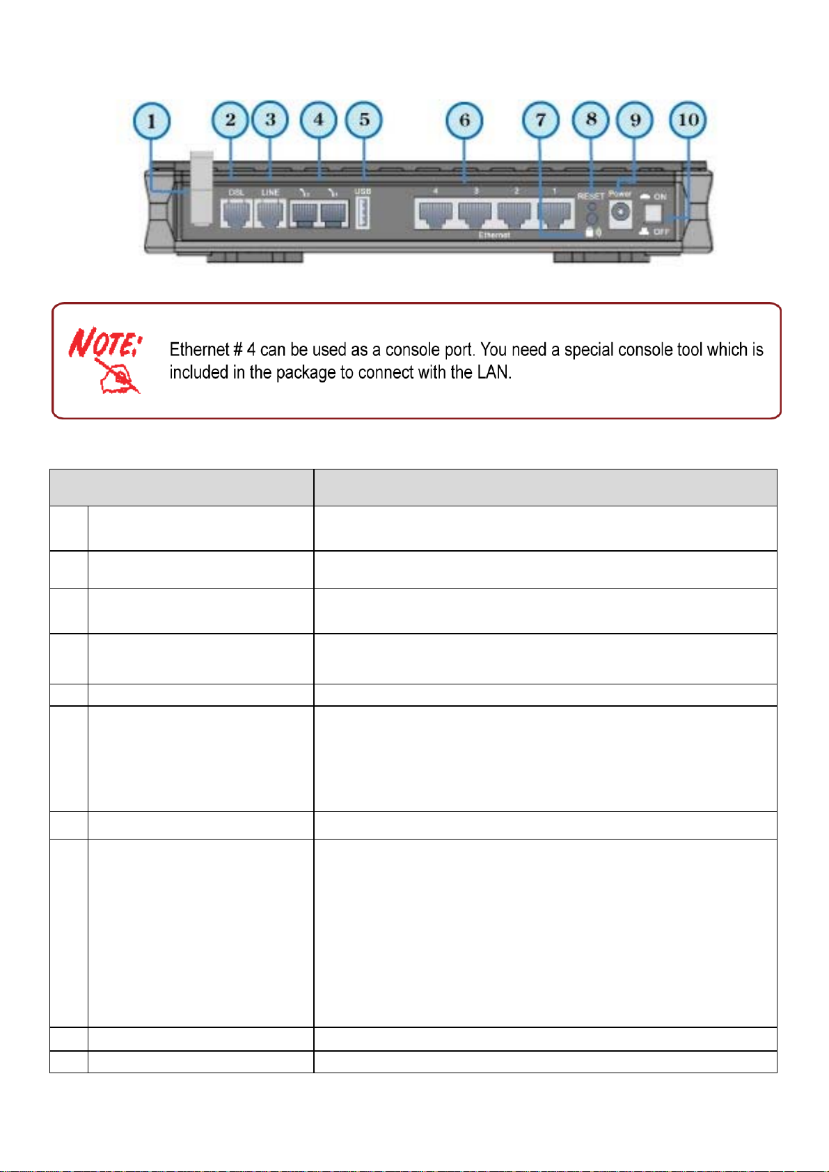
The Rear Ports
1
2 DSL
3
4
5 USB
6
Port
Antenna
(Wireless Router only)
Line
(Router with LINE port only)
Phone
1X-2X (RJ-11 connector)
Ethernet
1X - 4X
(RJ-45 connector)
Meaning
Connect the detachable antenna to this port.
Connect this port to the ADSL/telephone network with the RJ-
11 cable (telephone) provided.
Connect this port to the telephone jack on the wall with RJ-11
cable.
Connect this port to an analog phone set with RJ-11 cable.
Connect the USB cable to this port.
Connect a UTP Ethernet cable (Cat-5 or Cat-5e) to one of
the LAN ports when connecting to a PC or an office/home
network of 10Mbps or 100Mbps.
Caution: Port 4 can be either a LAN or Console port at a
time but not both.
7 WPS
8
RESET
9 Power
10 Power Switch
Push WPS button to trigger Wi-Fi Protected Setup function.
To be sure the device is being turned on press RESET button
for:
1-3 seconds: quick reset the device.
6 seconds and above, power off, power on the device: restore
to factory default settings. (Cannot login to the router or forgot
your Username/Password. Press the button for more than 6
seconds).
Caution: After pressing the RESET button for more than
6 seconds, to be sure you power cycle the device again.
Connect it with the supplied power adapter.
Power ON/OFF switch
7
Page 12

Cabling
One of the most common causes of problem is bad cabling or ADSL line(s). Make sure that all
connected devices are turned on. On the front panel of your router is a bank of LEDs. Verify that the
LAN Link and ADSL line LEDs are lit. If they are not, verify if you are using the proper cables.
Make sure that all devices (e.g. telephones, fax machines, analogue modems) connected to the same
telephone line as your router have a line filter connected between them and the wall outlet (unless
you are using a Central Splitter or Central Filter installed by a qualified and licensed electrician),
and that all line filters are correctly installed in a right way. If line filter is not installed and connected
properly, it may cause problem to your ADSL connection or may result in frequent disconnections.
8
Page 13

Chapter 3: Basic Installation
The router can be configured through your web browser. A web browser is included as a standard
application in the following operating systems: Linux, Mac OS, Windows 98/NT/2000/XP/Me/Vista,
etc. The product provides an easy and user-friendly interface for configuration.
Please check your PC network components. The TCP/IP protocol stack and Ethernet network
adapter must be installed. If not, please refer to your Windows-related or other operating system
manuals.
There are ways to connect the router, either through an external repeater hub or connect directly
to your PCs. However, make sure that your PCs have an Ethernet interface installed properly prior
to connecting the router device. You ought to configure your PCs to obtain an IP address through
a DHCP server or a fixed IP address that must be in the same subnet as the router. The default IP
address of the router is 192.168.1.254 and the subnet mask is 255.255.255.0 (i.e. any attached PC
must be in the same subnet, and have an IP address in the range of 192.168.1.1 to 192.168.1.253).
The best and easiest way is to configure the PC to get an IP address automatically from the router
using DHCP. If you encounter any problem accessing the router web interface it is advisable to
uninstall your firewall program on your PCs, as they can cause problems accessing the IP address
of the router. Users should make their own decisions on what is best to protect their network.
Please follow the following steps to configure your PC network environment.
9
Page 14
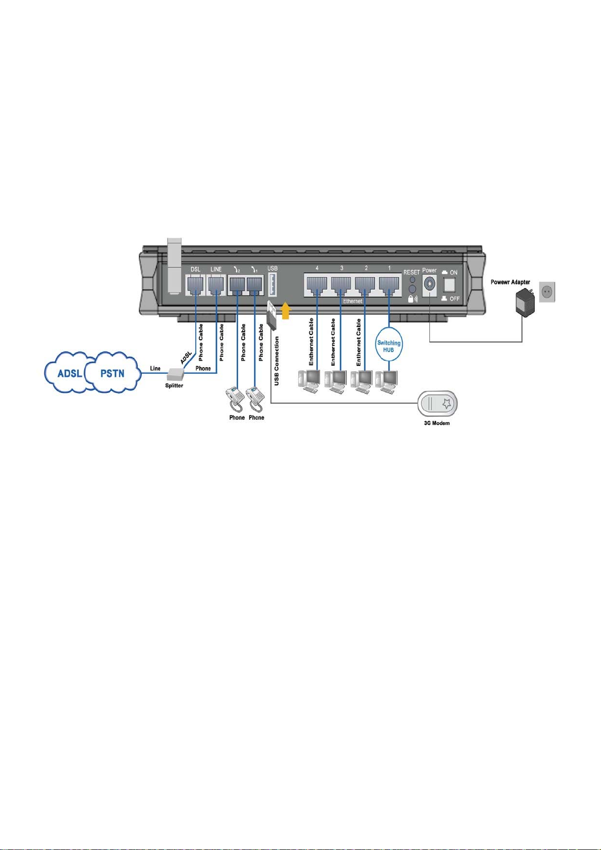
Connecting Your Router
1. Connect this router to a LAN (Local Area Network) and the ADSL/telephone (ADSL)
network.
2. Power on the device.
3. Make sure the Power LED lit steadily and that the LAN LED is lit.
4. Connect your router to the telephone jack on the wall with RJ-11 cable.
5. Connect the USB 2.0 cable.
10
Page 15
Network Configuration
Configuring PC in windows 7
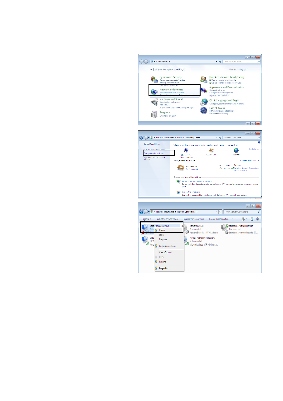
1. Go to Start. Click on Control Panel.
Then click on Network and Internet.
2. When the Network and Sharing Center
window pops up, select and click on
Change adapter settings on the left
window panel.
3. Select the Local Area Connection,
and right click the icon to select Properties.
11
Page 16
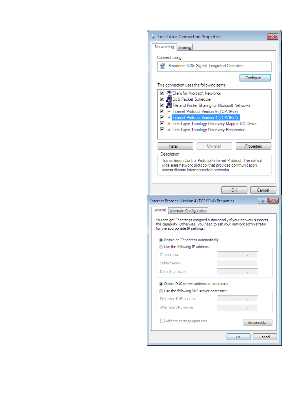
4. Select Internet Protocol Version 4
(TCP/IPv4) then click Properties.
5. In the TCP/IPv4 properties window,
select the Obtain an IP address automatically
and Obtain DNS Server address automatically
radio buttons. Then click OK to exit the setting.
6. Click OK again in the Local Area Connection
Properties window to apply the new configuration.
12
Page 17
Configuring PC in Windows Vista
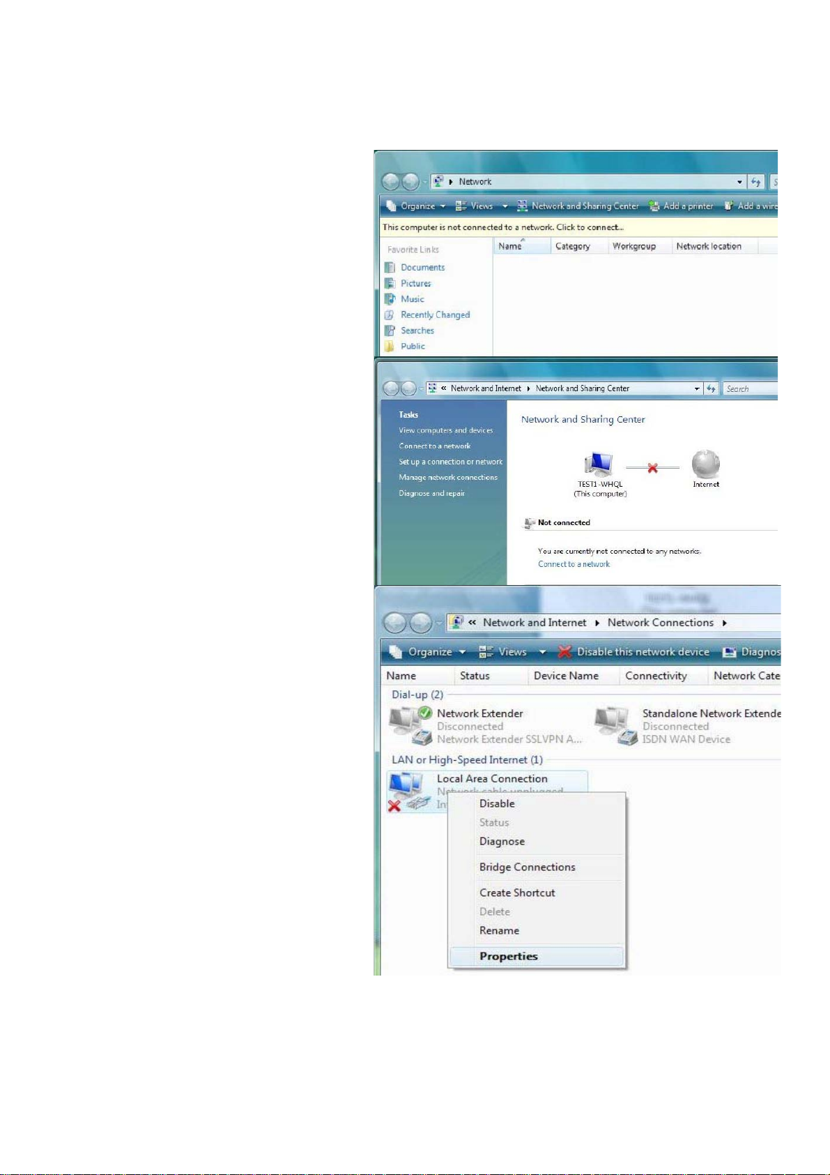
1. Go to Start. Click on Network.
2. Then click on Network and Sharing
Center at the top bar.
3. When the Network and Sharing
Center window pops up, select and
click on Manage network
connections on the left window
column.
4. Select the Local Area Connection,
and right click the icon to select
Properties.
13
Page 18
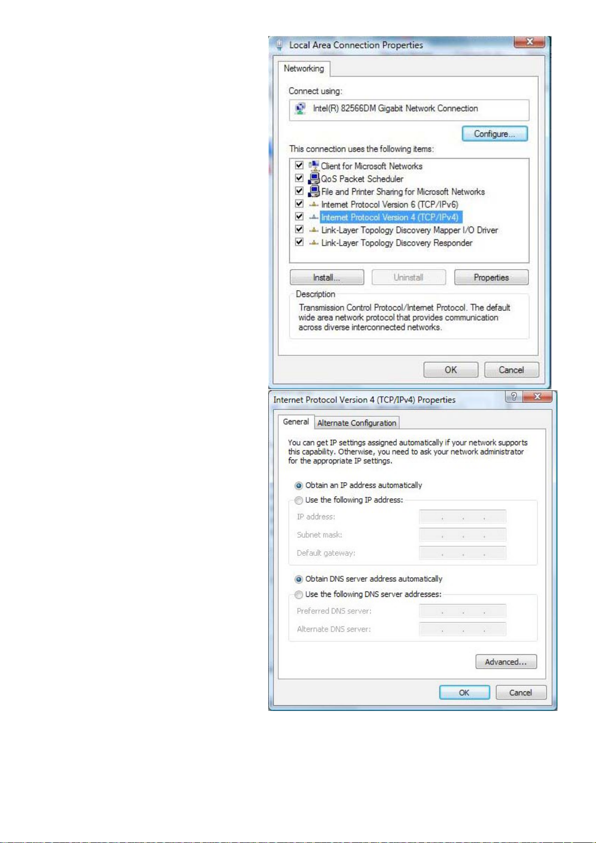
5. Select Internet Protocol Version 4
(TCP/IPv4) then click Properties.
6. In the TCP/IPv4 properties window,
select the Obtain an IP address
automatically and Obtain DNS
Server address automatically radio
buttons. Then click OK to exit the
setting.
7. Click OK again in the Local Area
Connection Properties window to
apply the new configuration.
14
Page 19
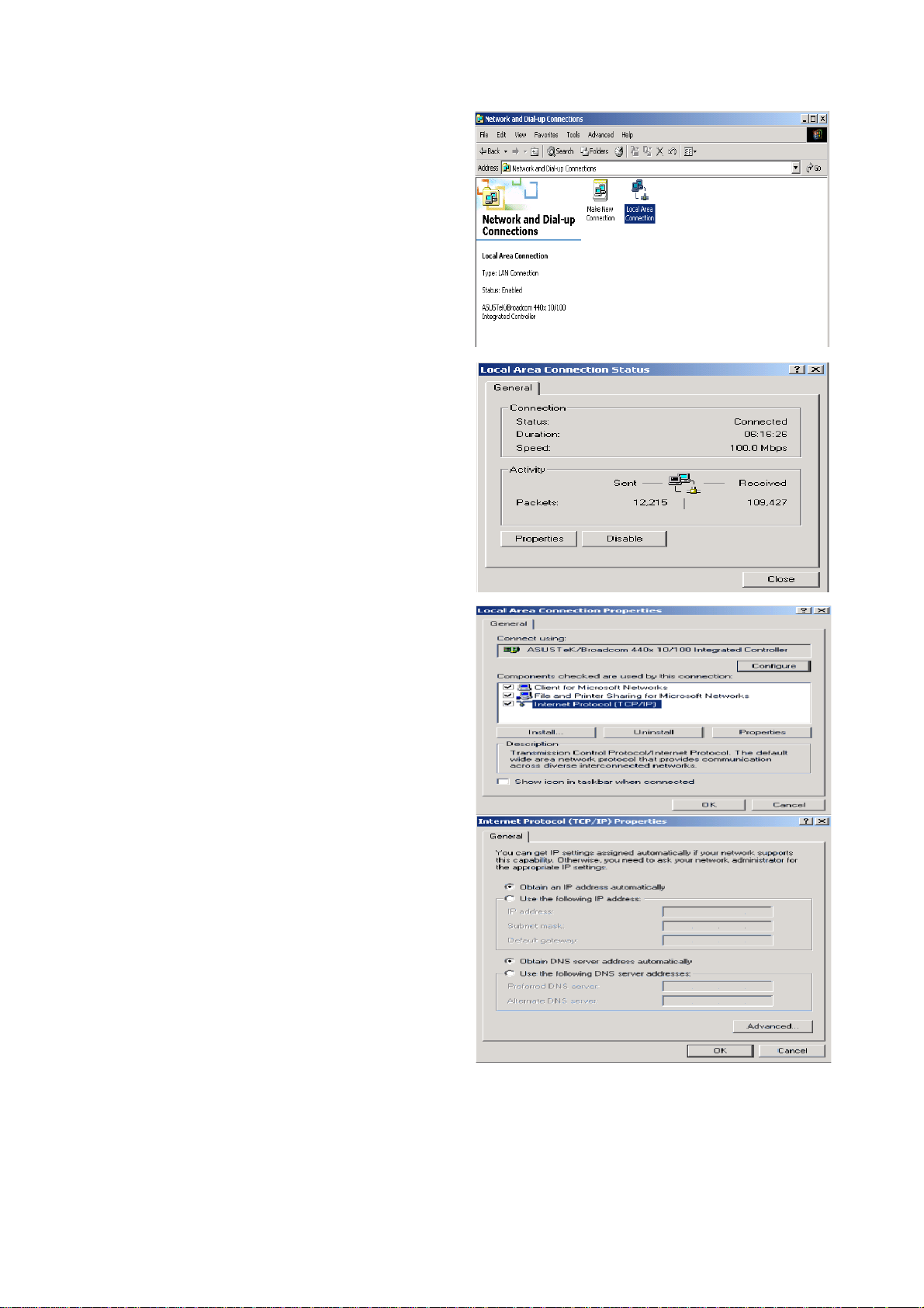
Configuring PC in Windows XP
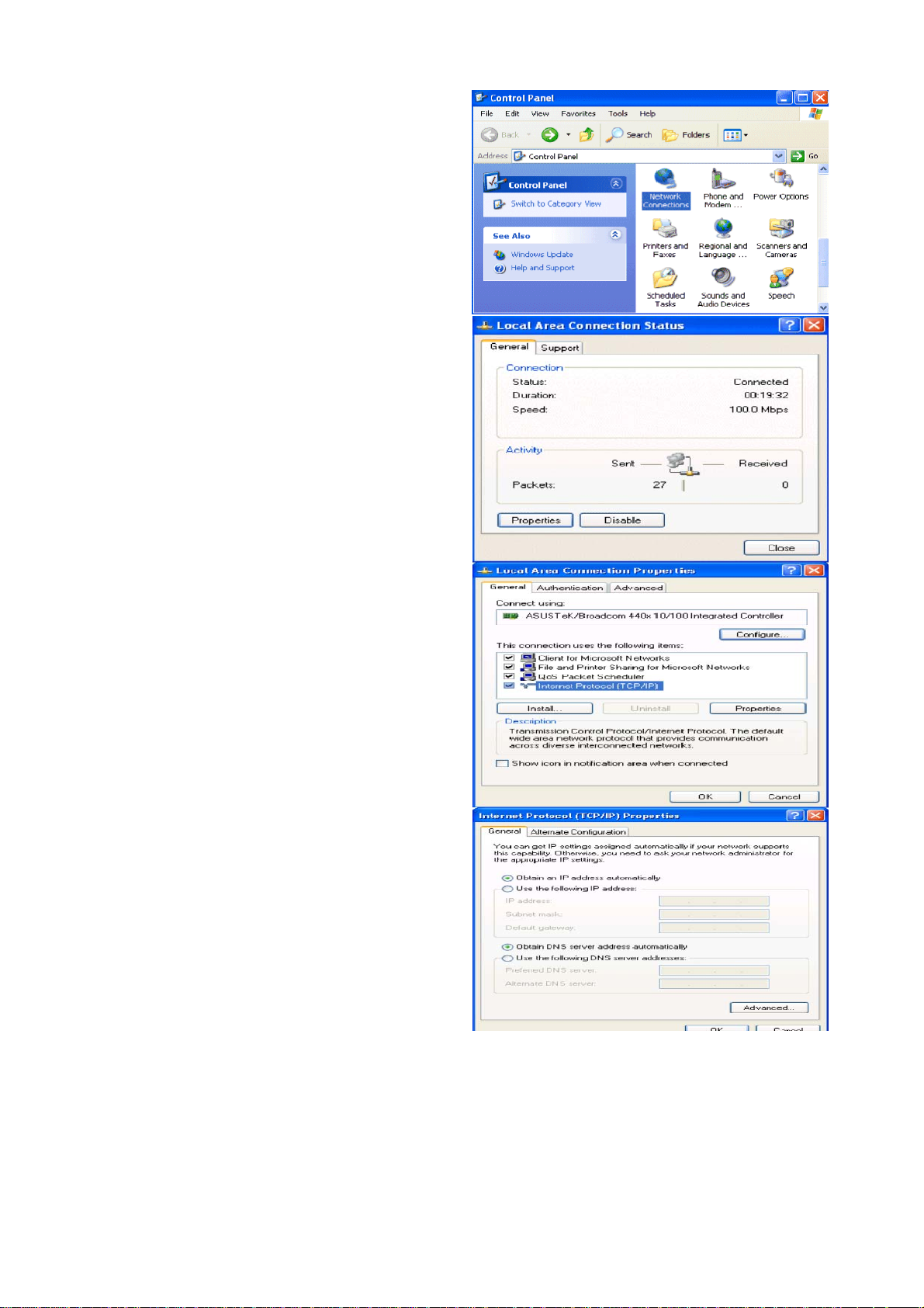
1. Go to Start > Control Panel (in Classic
View). In the Control Panel, double-click
on Network Connections
2. Double-click Local Area Connection.
3. In the Local Area Connection Status
window, click Properties.
4. Select Internet Protocol (TCP/IP) and
click Properties.
5. Select the Obtain an IP address
automatically and the Obtain DNS
server address automatically radio
buttons.
6. Click OK to finish the configuration.
15
Page 20
Configuring PC in Windows 2000
1. Go to Start > Settings > Control Panel.
In the Control Panel, double-click on
Network and Dial-up Connections.
2. Double-click Local Area Connection.
3. In the Local Area Connection Status
window click Properties.
4. Select Internet Protocol (TCP/IP) and
click Properties.
5. Select the Obtain an IP address automatically and the Obtain DNS server
address automatically radio buttons.
6. Click OK to finish the configuration.
16
Page 21
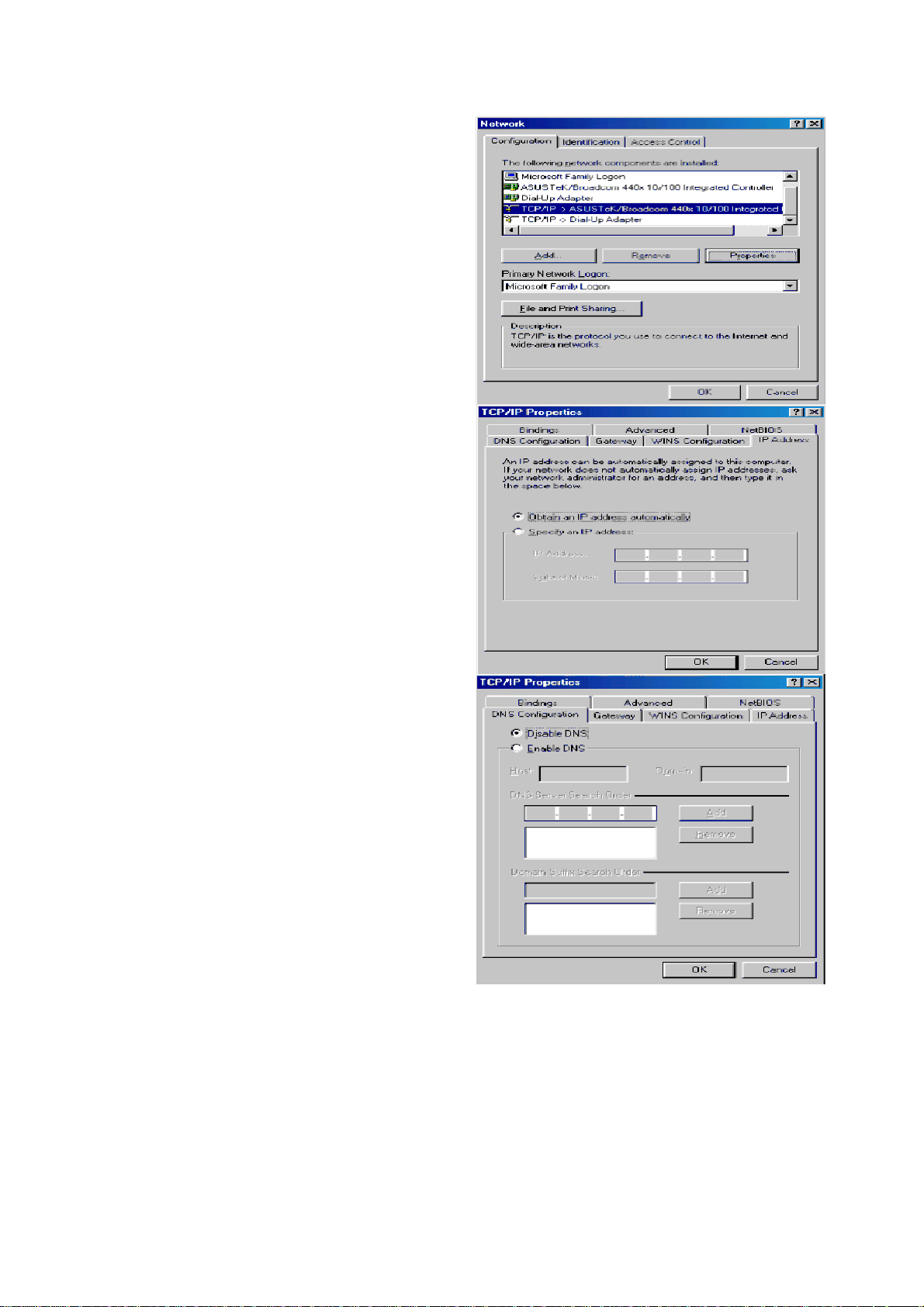
Configuring PC in Windows 95/98/Me
1. Go to Start > Settings > Control Panel.
In the Control Panel, double-click on
Network and choose the Configuration
tab.
2. Select TCP/IP > NE2000 Compatible,
or the name of your Network Interface
Card (NIC) in your PC.
3. Select the Obtain an IP address
automatically radio button.
4. Then select the DNS Configuration tab.
5. Select the Disable DNS radio button
and click OK to finish the configuration.
17
Page 22
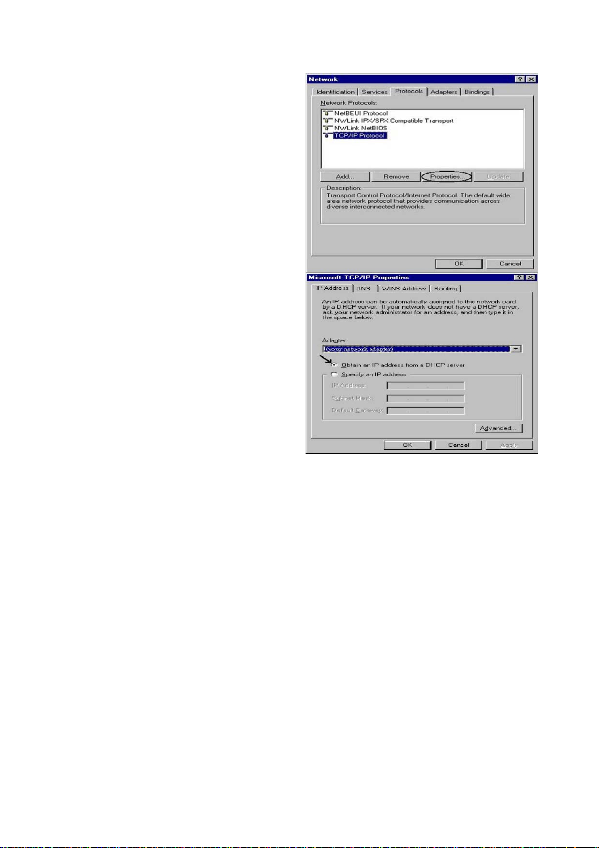
Configuring PC in Windows NT4.0
1. Go to Start > Settings > Control Panel.
In the Control Panel, double-click on
Network and choose the Protocols tab.
2. Select TCP/IP Protocol and click
Properties.
3. Select the Obtain an IP address from
a DHCP server radio button and click
OK.
18
Page 23
Factory Default Settings
Before configuring your router, you need to know the following default settings.
Web Interface (Username and Password)
Username: admin
Password: admin
The default username and password are “admin” and “admin” respectively.
Device LAN IP settings
IP Address: 192.168.1.254
Subnet Mask: 255.255.255.0
ISP setting in WAN site
PPPoE
DHCP server
DHCP server is enabled.
Start IP Address: 192.168.1.100
IP pool counts: 100
LAN and WAN Port Addresses
The parameters of LAN and WAN ports are pre-set in the factory. The default values are shown in
the table.
IP address
Subnet Mask
DHCP server function
IP addresses for
distribution to PCs
LAN Port
192.168.1.254
255.255.255.0
Enabled
100 IP addresses continuing
from 192.168.1.100 through
192.168.1.199
WAN Port
The PPPoE function is
enabled to automatically get
the WAN port configuration
from the ISP.
19
Page 24

Information from your ISP
Before configuring this device, you have to check with your ISP (Internet Service Provider) to find
out what kind of service is provided such as DHCP (Obtain an IP Address Automatically, Static IP
(Fixed IP Address) or PPPoE.
Gather the information as illustrated in the following table and keep it for reference.
PPPoE(RFC2516)
VPI/VCI, VC / LLC-based multiplexing, Username, Password, Service
Name, and Domain Name System (DNS) IP address (it can be
automatically assigned by your ISP when you connect or be set manually).
PPPoA(RFC2364)
MPoA(RFC1483/
RFC2684)
IPoA(RFC1577)
Pure Bridge
VPI/VCI, VC / LLC-based multiplexing, Username, Password and
Domain Name System (DNS) IP address (it can be automatically
assigned by your ISP when you connect or be set manually).
VPI/VCI, VC / LLC-based multiplexing, IP address, Subnet mask,
Gateway address, and Domain Name System (DNS) IP address (it is a
fixed IP address).
VPI/VCI, VC / LLC-based multiplexing, IP address, Subnet mask,
Gateway address, and Domain Name System (DNS) IP address (it is a
fixed IP address).
VPI/VCI, VC / LLC-based multiplexing to use Bridged Mode.
20
Page 25
Configuring with your Web Browser
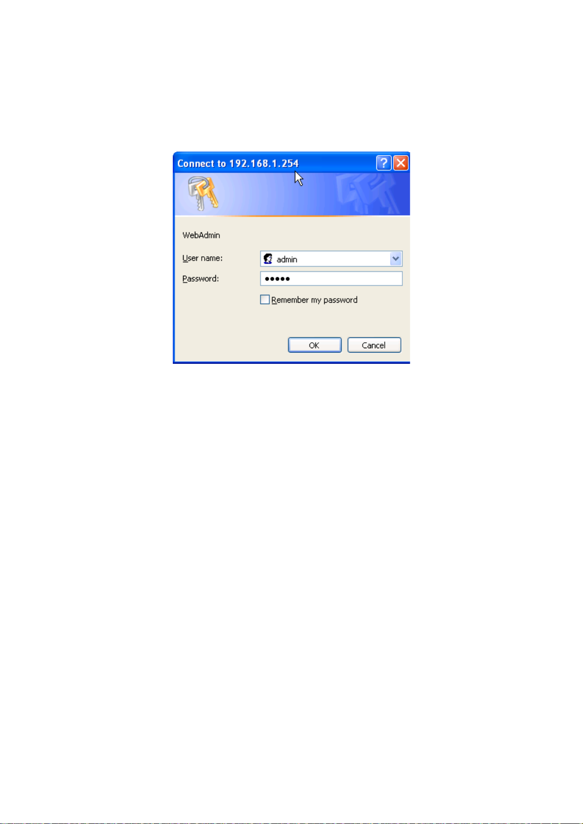
Open your web browser, enter the IP address of your router, which by default is 192.168.1.254,
and click “Go”, a user name and password window prompt will appear. The default username and
password are “admin” and “admin” respectively. (See Figure 3.14)
Figure 3.14: User name & Password Prompt Window
Congratulations! You are now successfully logon to the 3G/VoIP/(802.11g) ADSL2+ (VPN)
Firewall Router!
21
Page 26

Chapter 4: Configuration
At the configuration homepage, the left navigation column provides you the link to each configuration
page. The category of each configuration page is listed as below.
Status
ADSL Table
3G Status
EWAN Status
iBurst Status
ARP Table
DHCP Table
Routing Table
NAT Sessions
UPnP Pormap
PPTP Status
IPSec Status
L2TP Status
VoIP Status
VoIP Call Log
Event Log
Error Log
Diagnostic
Quick Start
Configuration
LAN
WAN
System
Firewall
VPN
VoIP
QoS
Virtual Server
Wake on LAN
Time Schedule
Advanced
Language (provides user interface in English and French languages)
22
Page 27
Status
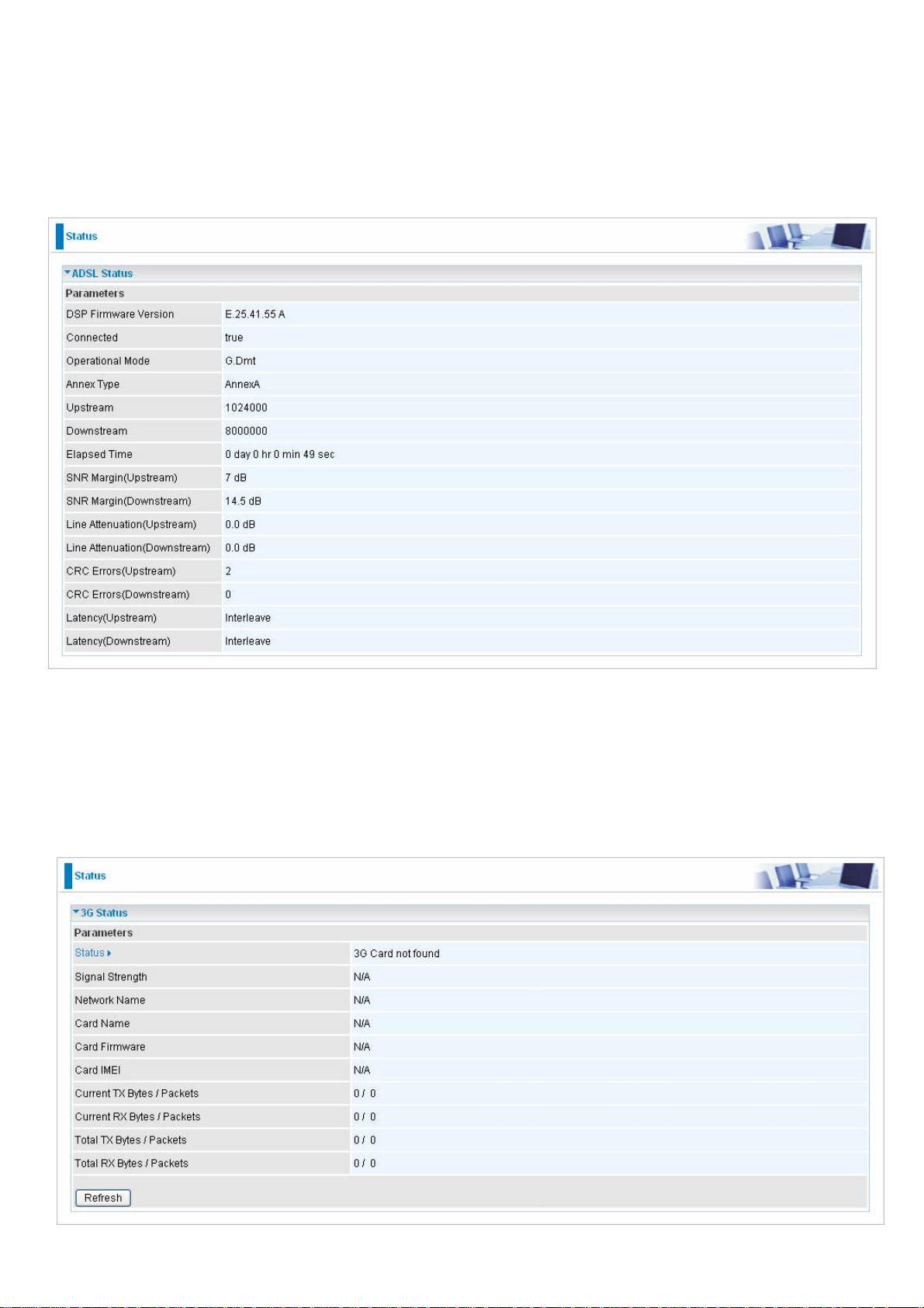
ADSL Status
This section displays the ADSL overall status, which shows a number of helpful information such
as DSP firmware version.
3G Status
This section displays the 3G Card’s overall status, which shows you a number of helpful
information such as the current signal strength and statistics on current and total bytes transferred
and received.
Status: The current status of the 3G card.
23
Page 28
Signal Strength: The signal strength bar indicates current 3G signal strength.
Network Name: The network name that the device is connected to.
Card Name: The name of the 3G card.
Card Firmware: The current firmware for the 3G card.
Card IMEI: the IMEI( International Mobile Equipment Identity) of the 3G card.
Current TX Bytes / Packets: The statistics of transmission, count for this call.
Current RX Bytes / Packets: The statistics of receive, count for this call.
Total TX Bytes / Packets: The statistics of transmission, count from system ready
Total RX Bytes / Packets: The statistics of receive, count from system ready
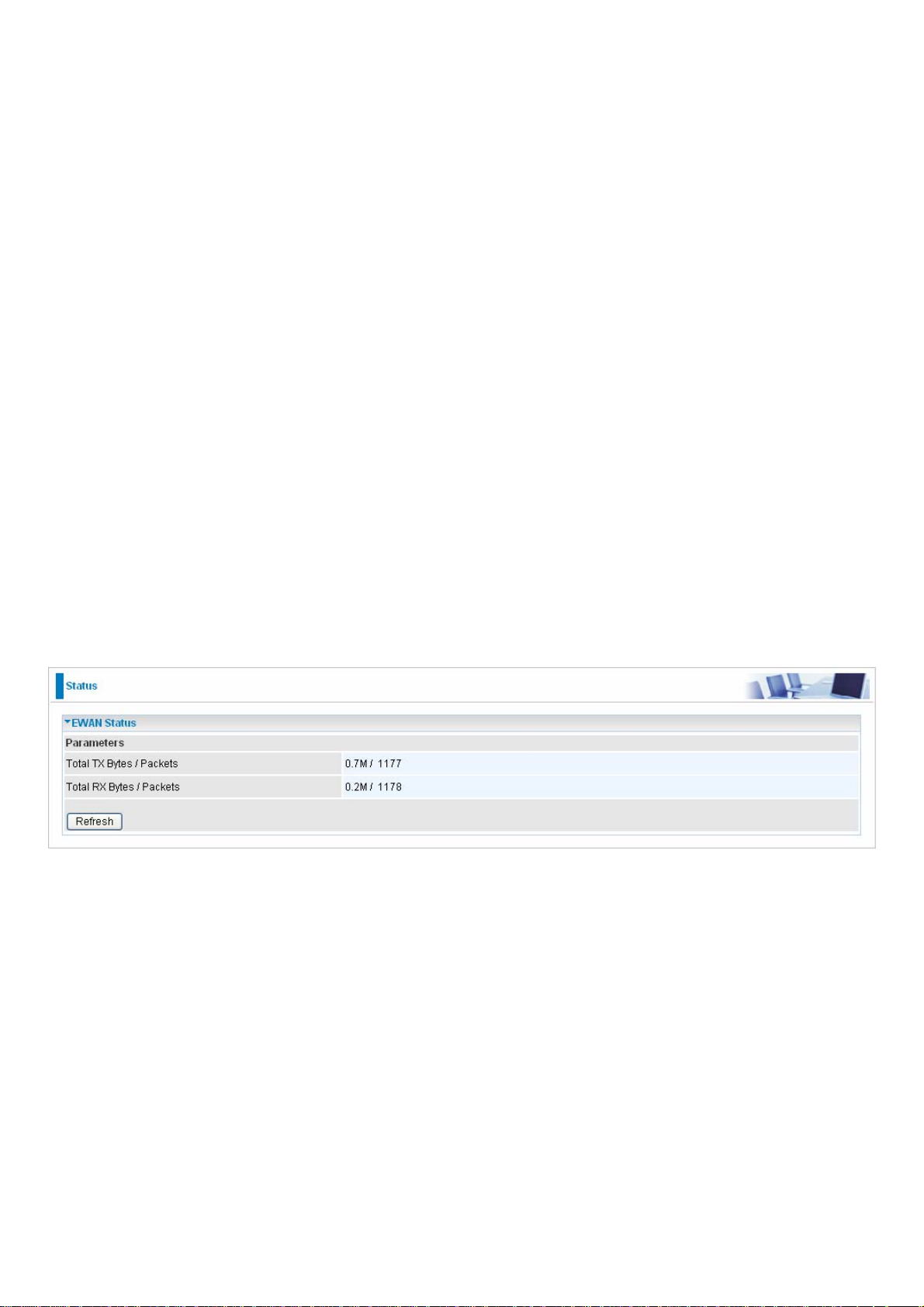
EWAN Status
Besides using 3G/ADSL to get connected to the Internet, the router offers its Ethernet port 1 as a
WAN port to be used to connect to Cable Modems and fiber optic lines. This alternative, yet faster
method to connect to the internet will provide users more flexibility to get online.
Total TX Bytes / Packets: The statistics of total data transmission in bytes / packets since
system ready.
Total RX Bytes / Packets: The statistics of total data received in bytes / packets since system
ready.
24
Page 29
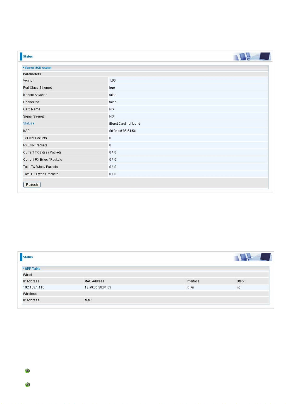
iBurst Status
Displays additional information of the 3G status when iBurst function is enabled in the 3G
configuration such as its signal strength, card name, connection status and port class Ethernet.
ARP Table
This section displays the router’s ARP (Address Resolution Protocol) Table, which shows the
mapping of Internet (IP) addresses to Ethernet (MAC) addresses. This is useful as a quick way of
determining the MAC address of the network interface of your PCs to use with the router’s Firewall
– MAC Address Filter function. See the Firewall section of this manual for more information on this
feature.
IP Address: A list of IP addresses of devices on your LAN (Local Area Network).
MAC Address: The MAC (Media Access Control) addresses for each device on your LAN.
Interface: The interface name (on the router) that this IP Address connects to.
Static: Static status of the ARP table entry:
“no” for dynamically-generated ARP table entries.
“yes” for static ARP table entries added by the user.
25
Page 30

DHCP Table
Leased: The DHCP assigned IP addresses information.
Expired: The expired IP addresses information.
Permanent: The fixed host mapping information.
26
Page 31

Leased Table
IP Address: The IP address that assigned to client.
MAC Address: The MAC address of client.
Client Host Name: The Host Name (Computer Name) of client.
Expiry: The current lease time of client.
27
Page 32

Routing Table
Routing Table
Valid: It indicates a successful routing status.
Destination: The IP address of the destination network.
Netmask: The destination Netmask address.
Gateway/Interface: The IP address of the gateway or existing interface that this route will use.
Cost: The number of hops counted as the cost of the route.
RIP Routing Table
Destination: The IP address of the destination network.
Netmask: The destination Netmask address.
Gateway: The IP address of the gateway that this route will use.
Cost: The number of hops counted as the cost of the route.
28
Page 33

NAT Sessions
This section lists all current NAT sessions between interface of types external (WAN) and internal
(LAN).
UPnP Portmap
The section lists all port-mapping established using UPnP (Universal Plug and Play. See Advanced
section of this manual for more details on UPnP and the router’s UPnP configuration options.
29
Page 34

PPTP Status
This shows details of your configured PPTP VPN Connections.
Name: The name you assigned to the particular PPTP connection in your VPN configuration.
Type: The type of connection (dial-in/dial-out).
Enable: Whether the connection is currently enabled.
Active: Whether the connection is currently active.
Tunnel Connected: Whether the VPN Tunnel is currently connected.
Call Connected: If the Call for this VPN entry is currently connected.
Encryption: The encryption type used for this VPN connection.
30
Page 35

IPSec Status
This shows details of your configured IPSec VPN Connections.
Name: The name you assigned to the particular VPN entry.
Active: Whether the VPN Connection is currently Active.
Connection State: Whether the VPN is Connected or Disconnected.
Statistics: Statistics for this VPN Connection.
Local Subnet: The local IP Address or Subnet used.
Remote Subnet: The Subnet of the remote site.
Remote Gateway: The Remote Gateway IP address.
SA: The Security Association for this VPN entry.
L2TP Status
This shows details of your configured L2TP VPN Connections.
Name: The name you assigned to the particular L2TP connection in your VPN configuration.
Type: The type of connection (dial-in/dial-out).
Enable: Whether the connection is currently enabled.
Active: Whether the connection is currently active.
Tunnel Connected: Whether the VPN Tunnel is currently connected.
Call Connected: If the Call for this VPN entry is currently connected.
Encryption: The encryption type used for this VPN connection.
31
Page 36

VoIP Status
This table shows the status of the phone ports after they are being used for the VoIP feature. It
will display some information such as domain name, display name & phone number of the VoIP
device.
VoIP Call Log
32
Page 37

Event Log
This page displays the router’s Event Log entries. Major events are logged to this window, such
as when the router’s ADSL connection is disconnected, as well as Firewall events when you have
enabled Intrusion or Blocking Logging in the Configuration – Firewall section of the interface.
Please see the Firewall section of this manual for more details on how to enable Firewall logging.
33
Page 38

Error Log
Any errors encountered by the router (e.g. invalid names given to entries) are logged to this
window.
Diagnostic
It tests the connection to computer(s) which is connected to the LAN ports and also the WAN Internet
connection. If PING www.google.com is shown FAIL and the rest is PASS, you ought to check your
PC’s DNS setting is correct.
34
Page 39

Quick Start
1. Click Quick Start. Select the connect mode you want. There are 2 options to choose from: ADSL
or 3G. Select ADSL mode from the drop down menu and click Continue.
2. If your ADSL line is not ready, you need to check your ADSL line has been set or not.
3. If your ADSL line is ready, the screen appears ADSL Line is Ready. Choose Auto radio button
and click Apply. It will automatically scan the recommended mode for you. Manually mode
makes you to set the ADSL line by manual. (If you choose Manually, you will directly go to step
5.)
4. The list below has different mode applied for your choice. Choose 0/33/PPPoE(Recommended)
and click Apply.
35
Page 40

5. Please enter “Username” and “Password” as supplied by your ISP(Internet Service Provider)
and click Apply to continue.
Profile Port: Select the connection mode. There is ADSL.
Protocol: Select the protocol mode. The default mode is PPPoE.
VPI/VCI: Enter the VPI and VCI information provided by your ISP.
Username: Enter the username provided by your ISP.
Password: Enter the password provided by your ISP.
Service Name: This item is for identification purposes. If it is required, your ISP provides you the
information.
Authentication Protocol: Default is Auto. Your ISP advises on using Chap or Pap.
MTU: Maximum Transmission Unit. The size of the largest datagram (excluding media-specific
headers) that IP will attempt to send through the interface.
IP Address: Your WAN IP address. Leave this at 0.0.0.0 to obtain automatically an IP address
from your ISP.
Obtain DNS automatically: Click to activate DNS and to enable the system to automatically
detect DNS.
Primary DNS / Secondary DNS: Enter the IP addresses of the DNS servers. The DNS servers
are passed to the DHCP clients along with the IP address and the netmask.
36
Page 41

6. Configure the Wireless LAN setting.
WLAN Service: Default setting is set to Enable. If you want to use wireless, both 802.11g and
802.11b device in your network, you can select Enable.
ESSID: The ESSID is the unique name of a wireless access point (AP) to be distinguished from
another. For security propose, change to a unique ID name to the AP which is already built-in to
the router’s wireless interface. It is case sensitive and must not excess 32 characters. Make sure
your wireless clients have exactly the ESSID as the device, in order to get connected to your
network.
ESSID Broadcast: It is function in which transmits its ESSID to the air so that when wireless client
searches for a network, router can then be discovered and recognized. Default setting is Enable.
Enable: When Enable is selected, you can allow anybody with a wireless client to be able to
locate the Access Point (AP) of your router.
Disable: Select Disable if you do not want broadcast your ESSID. When select Disable, no
one will be able to locate the Access Point (AP) of your router.
Regulation Domain: There are seven Regulation Domains for you to choose from, including
North America (N.America), Europe, France, etc. The Channel ID will be different based on this
setting.
Channel ID: Select the ID channel that you would like to use.
Security Mode: You can disable or enable with WPA or WEP for protecting wireless network. The
default mode of wireless security is Disable.
37
Page 42
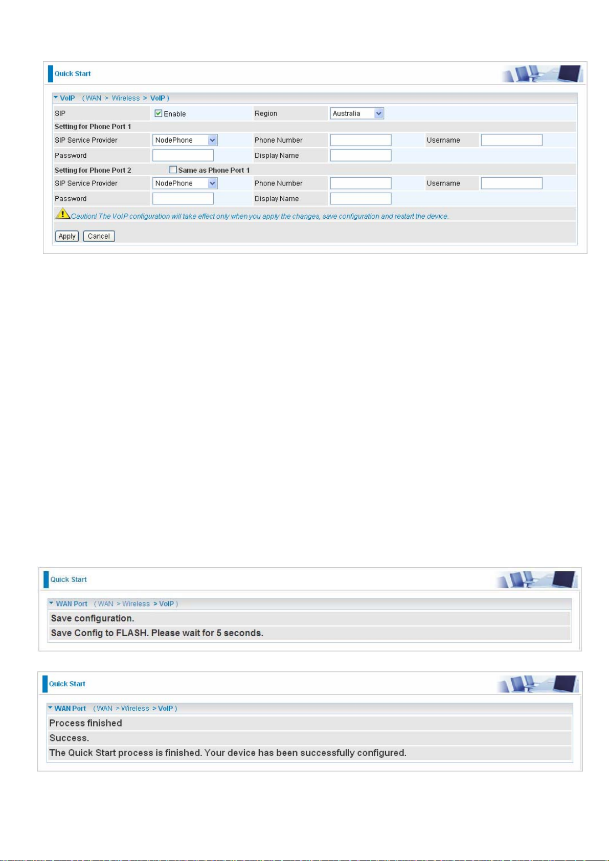
7. Set up VoIP.
SIP: To use VoIP SIP as VoIP call signaling protocol. Default is set to Disable.
Region: This selection is a drop-down box, which allows user to select the country for which the
VoIP device must work. When a country is selected, the country parameters are automatically
loaded.
SIP Service Provider: This section allows you to select the service provider. When the selection
is done, respective parameters below are automatically displayed.
Phone Number: This parameter holds the registration ID of the user within the VoIP SIP registrar.
Username: If the username is same as the Phone Number, leave it blank. Otherwise, fill in the
space with your username given by your VoIP provider.
Password: This parameter holds the password used for authentication within VoIP SIP registrar.
Display Name: This parameter will be appeared on the Caller ID.
8. Wait for the configuration.
38
Page 43

9. When ADSL is synchronic, it will appear “check”.
39
Page 44

Configuration
When you click this item, the column will expand to display the sub-items that will allow you to further
configure your ADSL router.
LAN, WAN, System, Firewall, VPN, VoIP, QoS, Virtual Server, Wake on LAN, Time Schedule
and Advanced
The function of each configuration sub-item is described in the following sections.
40
Page 45

LAN - Local Area Network
Here are the items within the LAN section: Bridge Interface, Ethernet, IP Alias, Ethernet Client
Filter, Wireless, Wireless Security, Wireless Client Filter, WPS, Port Setting and DHCP
Server.
Bridge Interface
You can setup member ports for each VLAN group under Bridge Interface section. From the example,
two VLAN groups need to be created.
Ethernet: P1 (Port 1)
Ethernet1: P2, P3 and P4 (Port 2, 3, 4). Uncheck P2, P3, P4 from Ethernet VLAN port first.
Note: You should setup each VLAN group with caution. Each Bridge Interface is arranged in
this order.
Bridge Interface VLAN Port (Always starts with)
ethernet P1 / P2 / P3 / P4
ethernet1 P2 / P3 / P4
ethernet2 P3 / P4
ethernet3
P4
Management Interface: To specify which VLAN group has possibility to do device management,
like doing web management.
Note: NAT/NAPT can be applied to management interface only.
41
Page 46

Ethernet
Primary IP Address
IP Address: The default IP on this router.
Subnet Mask: The default subnet mask on this router.
RIP: RIP v1, RIP v2, and RIP v2 Multicast. Check to enable RIP function.
IP Alias
This function creates multiple virtual IP interfaces on this router. It helps to connect two or more local
networks to the ISP or remote node. In this case, an internal router is not required.
IP Address: Specify an IP address on this virtual interface.
SubNetmask: Specify a subnet mask on this virtual interface.
Security Interface: Specify the firewall setting on this virtual interface.
Internal: The network is behind NAT. All traffic will do network address translation when
sending out to Internet if NAT is enabled.
External: There is no NAT on this IP interface and connected to the Internet directly. Mostly
it will be used when providing multiple public IP addresses by ISP. In this case, you can use
public IP address in local network which gateway IP address point to the IP address on this
interface.
DMZ: Specify this network to DMZ area. There is no NAT on this interface.
42
Page 47

Ethernet Client Filter
The Ethernet Client Filter supports up to 16 Ethernet network machines that helps you to
manage your network control to accept traffic from specific authorized machines or can restrict
unwanted machine(s) to access your LAN.
There are no pre-define Ethernet MAC address filter rules; you can add the filter rules to meet
your requirements.
Ethernet Client Filter: Default setting is set
Disable.
Allowed: check to authorize specific device accessing your LAN by insert the MAC
Address in the space provided or click the Candidate button. Make sure your PC’s MAC
The maximum client is 16.The MAC addresses are 6 bytes long; they are presented only in
hexadecimal characters. The number 0 - 9 and letters a - f are
acceptable.
Note: Follow the MAC Address Format xx:xx:xx:xx:xx:xx. Semicolon ( : ) must be
included.
Candidates: automatically detects devices connected to the router through the
is listed.
Blocked: check to prevent unwanted device accessing your LAN by insert the MAC
Address in the space provided or click the Candidate button. Make sure your PC’s MAC is
not listed.
Ethernet. . Click the Candidate button to access the Active PC in LAN window.
43
Page 48

Active PC in LAN: Active PC in LAN displays a list of individual Ethernet device’s IP Address
&MAC Address which connecting to the router.
You can easily by checking the box next to the IP address to be blocked or allowed. Then, Add to
insert to the Ethernet Client Filter table. The maximum Ethernet client is 16.
44
Page 49

Wireless
Parameters
WLAN Service: Default setting is set to Enable. If you do not have any wireless, both 802.11g and
802.11b, device in your network, select Disable.
Mode: The default setting is 802.11b+g (Mixed mode). If you do not know or have both 11g and
11b devices in your network, then keep the default in mixed mode. From the drop-down manual,
you can select 802.11g if you have only 11g card. If you have only 11b card, then select 802.11b.
ESSID: The ESSID is the unique name of a wireless access point (AP) to be distinguished from
another. For security purpose, change the default wlan-ap to a unique ID name to the AP already
built-in to the router’s wireless interface. It is case sensitive and must not excess 32 characters.
Make sure your wireless clients have exactly the ESSID as the device, in order to get connected to
your network.
Note: It is case sensitive and must not excess 32 characters.
ESSID Broadcast: It is function in which transmits its ESSID to the air so that when wireless client
searches for a network, router can then be discovered and recognized. Default setting is Enabled.
Disable: If you do not want broadcast your ESSID. Any client uses “any” wireless setting
cannot discover the Access Point (AP) of your router.
Enable: Any client that using the “any” setting can discover the Access Point (AP).
Regulation Domain: There are seven Regulation Domains for you to choose from, including North
America (N.America), Europe, France, etc. The Channel ID will be different based on this setting.
Channel ID: Select the wireless connection ID channel that you would like to use.
45
Page 50

Note: Wireless performance may degrade if select ID channel is already being occupied by
other AP(s).
TX PowerLevel: It is a function that enhances the wireless transmitting signal strength. User may
adjust this power level from minimum 1 up to maximum 127.
Note: The Power Level maybe different in each access network user premises environment
and choose the most suitable level for your network.
Connected: Representing in true or false. That it is the connection status between the system
and the build-in wireless card.
AP MAC Address: It is a unique hardware address of the Access Point.
AP Firmware Version: The Access Point firmware version.
WMM: This feature works concurrently with QoS that enables the system to prioritize the flow of
data packets according to 4 categories: Voice, Video, Best Efforts and Background.
Enable: Click to activate WMM feature.
Disable: Click to deactivate WMM feature
Wireless Distribution System (WDS)
It is a wireless access point mode that enables wireless link and communication with other access
point. It is easy to be installed simply to define peer’s MAC address of the connected AP. WDS takes
advantages of cost saving and flexibility which no extra wireless client device is required to bridge
between two access points and extending an existing wired or wireless infrastructure network to
create a larger network. It can connect up to 4 wireless APs for extending cover range at the same
time.
In addition, WDS enhances its link connection security in WEP mode, WEP key encryption must be
the same for both access points.
WDS Service: The default setting is Disabled. Check Enable radio button to activate this function.
1. Peer WDS MAC Address: It is the associated AP’s MAC Address. It is important that your
peer’s AP must include your MAC address in order to acknowledge and communicate with each
other.
2. Peer WDS MAC Address: It is the second associated AP’s MAC Address.
3. Peer WDS MAC Address: It is the third associated AP’s MAC Address.
4. Peer WDS MAC Address: It is the fourth associated AP’s MAC Address.
Note: For MAC Address, Semicolon ( : ) must be included.
46
Page 51

Wireless Security
You can disable or enable with WPA or WEP for protecting wireless network.
The default mode of wireless security is disabled.
47
Page 52

WPA-PSK / WPA2-PSK
Security Mode: You can disable or enable with WPA or WEP for protecting wireless network. The
default mode of wireless security is Disable.
WPA Algorithms: There are two types of the WPA-PSK, WPA-PSK and WPA2-PSK. The WPA-
PSK adapts the TKIP (Temporal Key Integrity Protocol) encrypted algorithms, which incorporates
Message Integrity Code (MIC) to provide protection against hackers. The WPA2-PSK adapts
CCMP (Cipher Block Chaining Message Authentication Code Protocol) of the AES (Advanced
Encryption Security) algorithms.
WPA Shared Key: The key for network authentication. The input format is in character style and
key size should be in the range between 8 and 63 characters.
Group Key Renewal: The period of renewal time for changing the security key automatically
between wireless client and Access Point (AP). Default value is 600 seconds.
WEP
WEP Authentication: To prevent unauthorized wireless stations from accessing data transmitted
over the network, the router offers secure data encryption, known as WEP. If you require high
security for transmissions, there are two options to select from: Open System, Share key.
WEP Encryption: To prevent unauthorized wireless stations from accessing data transmitted over
the network, the router offers highly secure data encryption, known as WEP. If you require high
security for transmissions, there are two alternatives to select from: WEP 64 and WEP 128. WEP
48
Page 53

128 will offer increased security over WEP 64.
Passphrase: This is used to generate WEP keys automatically based upon the input string and a
pre-defined algorithm in WEP64 or WEP128.
Default Used WEP Key: Select the encryption key ID; please refer to Key (1~4) below.
Key (1-4): Enter the key to encrypt wireless data. To allow encrypted data transmission, the WEP
Encryption Key values on all wireless stations must be the same as the router. There are four keys
for your selection. The input format is in HEX style, 10 and 26 HEX codes are required for WEP64
and WEP128 respectively.
49
Page 54

Wireless Client / MAC Address Filter
The MAC Address supports up to 16 wireless network machines and helps you manage your network
control to accept traffic from specific authorized machines or to restrict unwanted machine(s) to
access your LAN.
There are no pre-define MAC Address filter rules; you can add the filter rules to meet your
requirements.
Wireless Client Filter: Default setting is set to Disable.
Allowed: To authorize specific device accessing your LAN by insert the MAC Address in the
space provided or click the Candidate button. Make sure your PC’s MAC is listed.
Blocked: To prevent unwanted device accessing the LAN by insert the MAC Address in the
space provided or click the Candidate button. Make sure your PC’s MAC is not listed.
The maximum client is 16. The MAC addresses are 6 bytes long; they are presented only in
hexadecimal characters. The number 0 - 9 and letters a - f are acceptable.
Note: Follow the MAC Address Format xx:xx:xx:xx:xx:xx. Semicolon ( : ) must be included.
Candidates: It automatically detects devices connected to the router through the Wireless feature.
Click the Candidate button to access the Associated Wireless Client window.
50
Page 55

Associate Wireless Client: Displays a list of individual wireless device’s MAC Address that currently
connects to the router.
You can easily by checking the box next to the MAC address to be blocked or allowed. Then, Add to
insert to the Wireless Client (MAC Address) Filter table. The maximum Wireless client is 16.
WPS
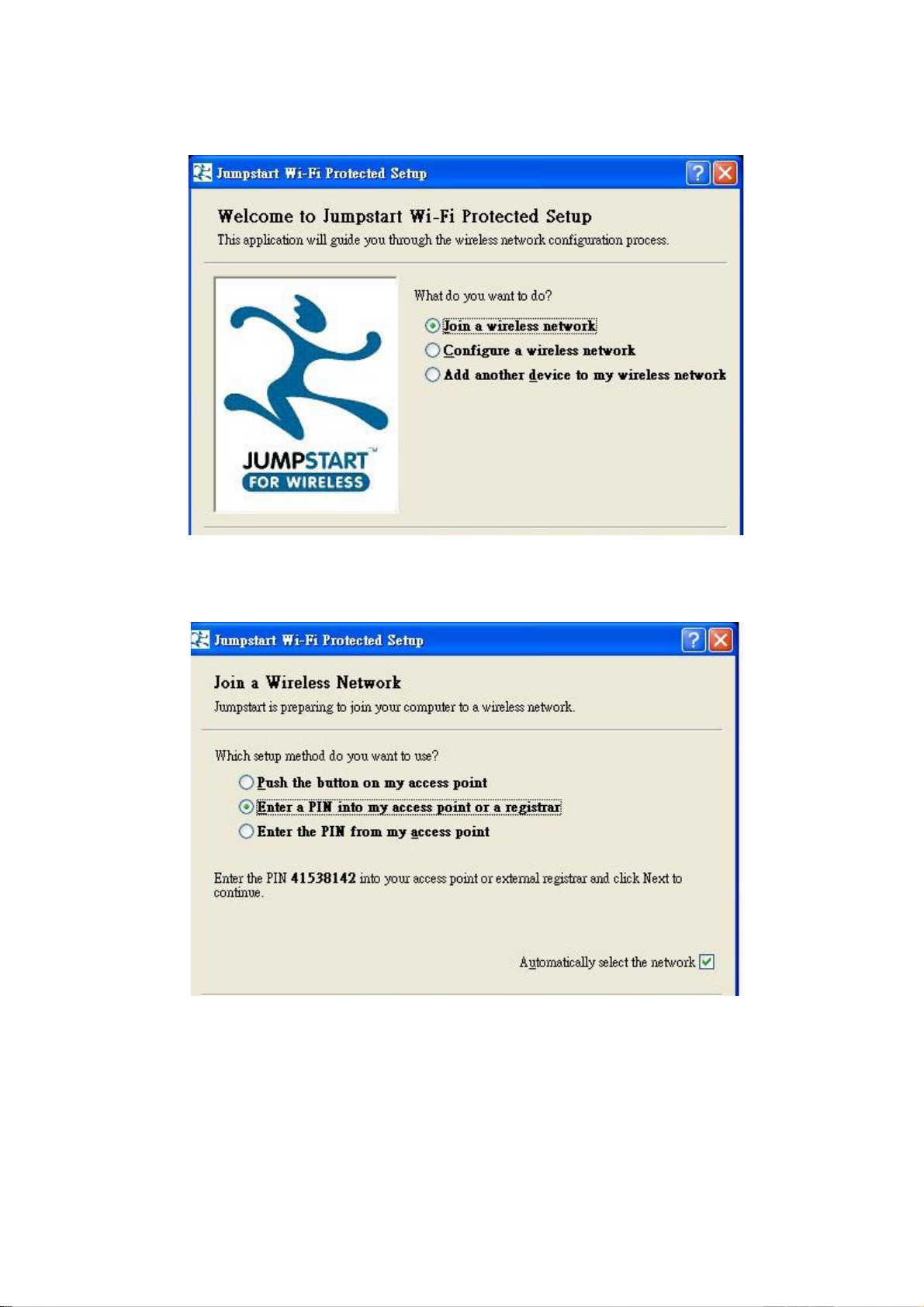
WPS feature is follow Wi-Fi Alliance WPS standard and it easily set up security-enabled Wi- Fi
networks in the home and small office environment. It is reduced by half the user steps to
configure a network and supports two methods that are familiar to most consumers to configure a
network and enable security.
Set up of security-enabled Wi-Fi network
Step 1: Note down the AP’s PIN from Web (Ex: 90932489).
Step 2: Open wireless client’s WPS utility (Ex: Atheros Jumpstart WPS utility), select “Configure a
wireless network” and apply “next” button.
51
Page 56

Step 3: Enter AP’s PIN into the utility and click on the “next” button.
Step 4: These are two ways to trigger AP as Enrollee role, you can choose one to do it.
Push AP’s WPS button 1 second and release it. Or
In the AP’s WPS configuration page, change Role to “Enrollee” and apply “Start” button.
52
Page 57
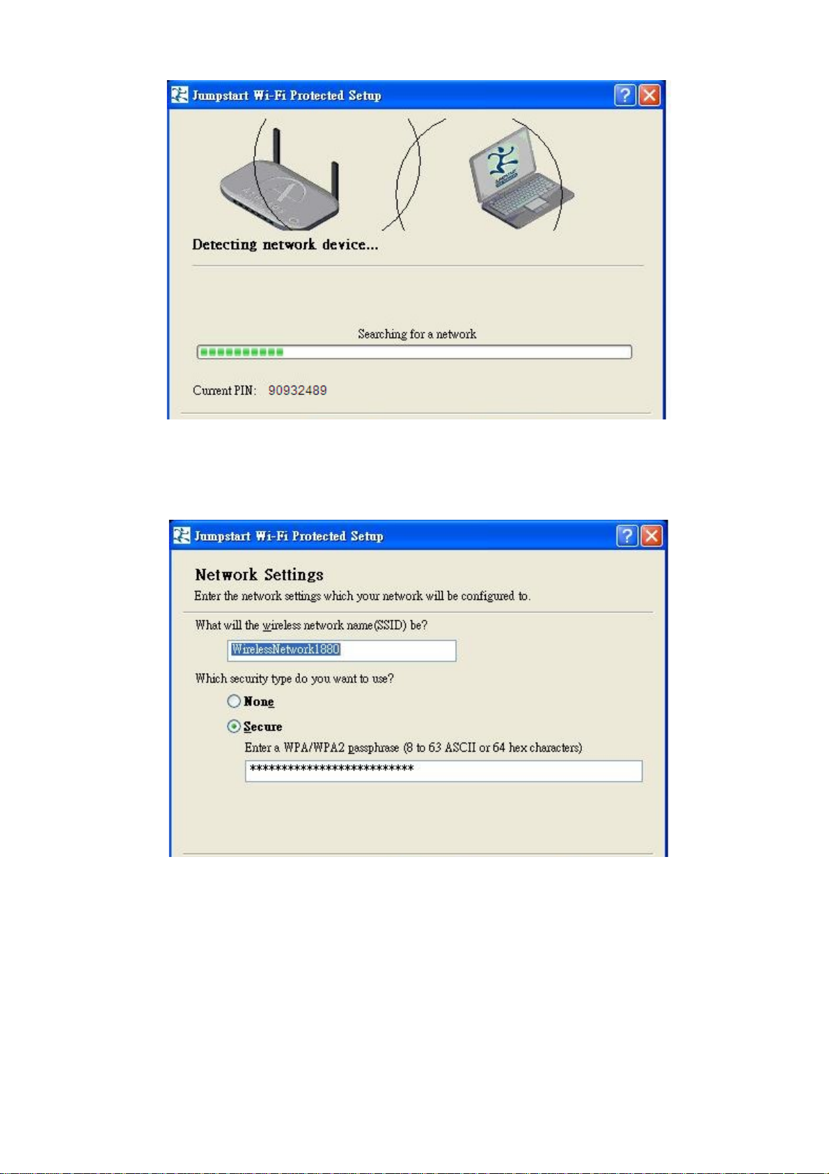
Step 5: Jump start WPS utility search WPS AP.
Step 6: SSID and security will be generated automatically (You can change it) and apply
“next” button.
53
Page 58

Step 7: WPS set up complete. And you have set up security-enabled Wi-Fi networks.
Set up of security-enabled Wi-Fi network using WCN in Vista
Step 1: Note down the AP’s PIN from Web (Ex: 90932489).
Step 2: In Vista`s Control Panel, select Network and Internet and choose View network
computers and devices. Double click the “ADSL Firewall Router” icon and enter the AP’s PIN code
then click “Next”.
54
Page 59

Step 3: Enter the AP SSID and apply “Next” button.
Step 4: Enter the Passphrase and apply “Next” button.
55
Page 60

Step 5: WCN set up complete. And you have set up security-enabled Wi-Fi networks.
Adding a new WPS device (wireless client) to a network - Use PBC Method
Step 1: Push AP’s WPS button more than one second and you will see AP’s WLAN led will flashing
per second.
Step 2: Open wireless client’s WPS utility, select “Join a wireless network” and apply “next” button.
Note: After you push AP’s WPS button, below steps should be completed between 2 minutes.
56
Page 61

Step 3: Select “Push the button on my access point” and apply “next” button.
Step 4: New WPS device have join into the wireless network.
57
Page 62
Adding a new WPS device (wireless client) to a network - Use PIN Method
Step 1: Open wireless client’s WPS utility, select “Join a wireless network” and apply “next” button
Step 2: Note down the wireless client’s PIN (Ex: 41538142) and apply “Start” button for active
wireless client WPS PIN method.
58
Page 63
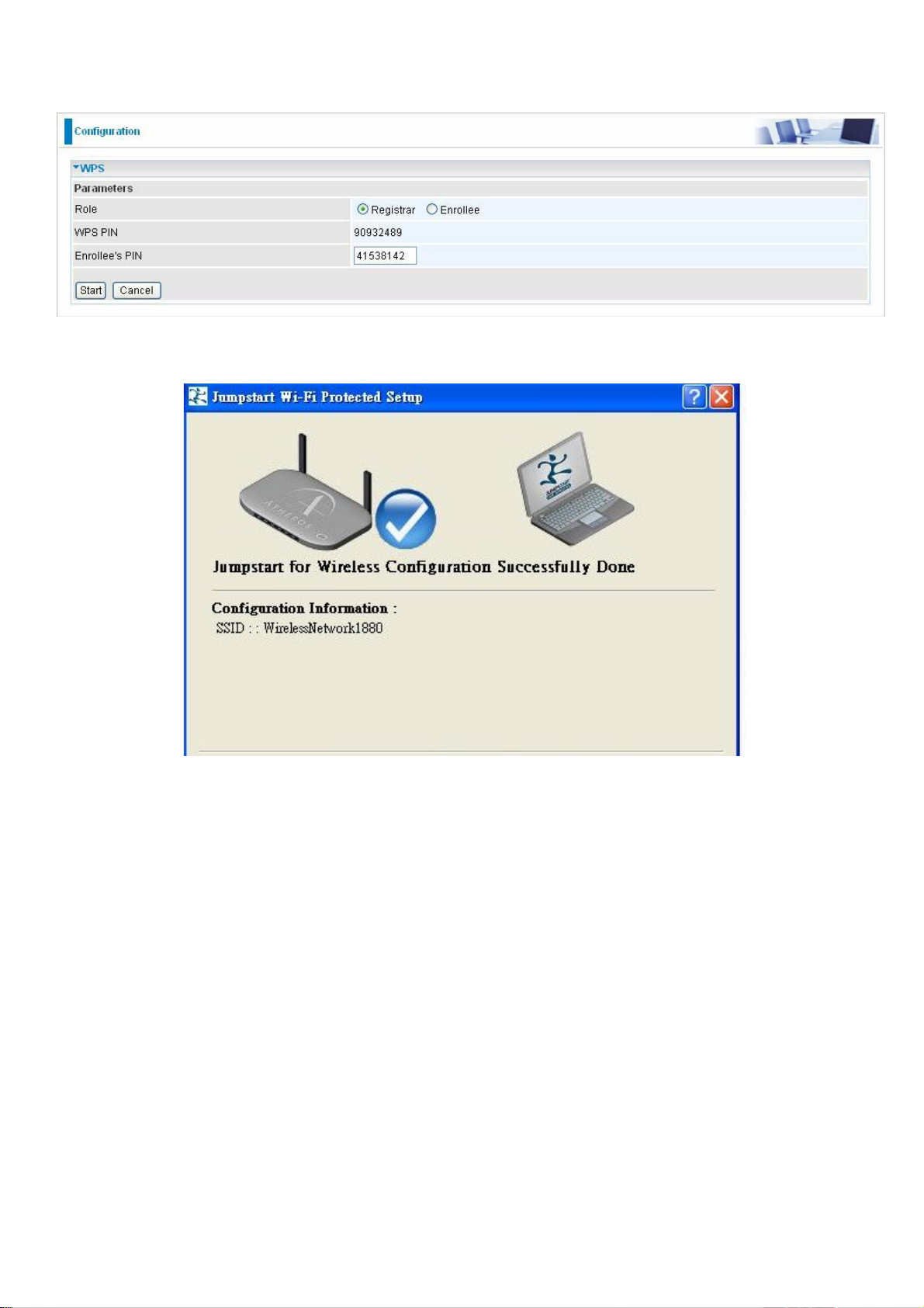
Step 3: Enter wireless client’s PIN into “Enrollee’s PIN” of Web and apply “Start” button.
Step 4: New WPS device have join into the wireless network.
59
Page 64

Port Setting
This section allows you to configure the settings for the router’s Ethernet ports to solve some
of the compatibility problems that may be encountered while connecting to the Internet, as well
allowing users to tweak the performance of their network.
Port # Connection Type: There are Six options to choose from: Auto, disable, 10M half-duplex,
10M full-duplex, 100M half-duplex, 100M full-duplex and Disable. Sometimes, there are Ethernet
compatibility problems with legacy Ethernet devices, and you can configure different types to
solve compatibility issues. The default is Auto, which users should keep unless there are specific
problems with PCs not being able to access your LAN.
IPv4 TOS priority Control (Advanced users): TOS, Type of Services, is the 2
nd
octet of an IP
packet. Bits 6-7 of this octet are reserved and bit 0-5 are used to specify the priority of the packet.
This feature uses bits 0-5 to classify the packet’s priority. If the packet is high priority, it will flow
first and will not be constrained by the Rate Limit. Therefore, when this feature is enabled, the
router’s Ethernet switch will check the 2
nd
octet of each IP packet. If the value in the TOS field
matches the checked values in the table (0 to 63), this packet will be treated as high priority.
60
Page 65

DHCP Server
You can disable or enable the DHCP (Dynamic Host Configuration Protocol) server or enable the
router’s DHCP relay functions. The DHCP protocol allows your router to dynamically assign IP
addresses to PCs on your network if they are configured to obtain IP addresses automatically.
To disable the router’s DHCP Server, check Disabled and click Next, then click Apply. When the
DHCP Server is disabled you will need to manually assign a fixed IP address to each PCs on your
network, and set the default gateway for each PCs to the IP address of the router (by default this is
192.168.1.254).
To configure the router’s DHCP Server, check DHCP Server and click Next. You can then configure
parameters of the DHCP Server including the IP pool (starting IP address and ending IP address to
be allocated to PCs on your network), lease time for each assigned IP address (the period of time
the IP address assigned will be valid), DNS IP address and the gateway IP address. These details
are sent to the DHCP client (i.e. your PC) when it requests an IP address from the DHCP server.
Click Apply to enable this function. If you check “Use Router as a DNS Server”, the ADSL Router will
perform the domain name lookup, find the IP address from the outside network automatically and
forward it back to the requesting PC in the LAN (your Local Area Network).
If you check DHCP Relay Agent and click Next, then you will have to enter the IP address of the
DHCP server which will assign an IP address back to the DHCP client in the LAN. Use this function
only if advised to do so by your network administrator or ISP.
Click Apply to enable this function.
61
Page 66

WAN - Wide Area Network
WAN refers to your Wide Area Network connection, i.e. your router’s connection to your ISP and
the Internet. Here are the items within the WAN section: WAN Interface, WAN Profile and ADSL
Mode.
WAN Interface
ADSL Mode
The default setting for Connection Mode is ADSL and for Protocol is PPPoE.
3G Mode
In ADSL mode, as the ADSL is not available (failover/failback), it will switch to 3G mode for WAN
Connection support. However, in 3G Mode ADSL cannot support WAN Connection when 3G
Mode is unavailable.
62
Page 67

EWAN
EWAN is another way of getting connected to the Internet, the router offers its Ethernet port 1 as a
WAN port to be used to connect to Cable Modems and fiber optic lines. This alternative, yet faster
method to connect to the internet will provide users more flexibility to get online. When the above
two mode is not valid,the way can be adopted.
Dual WAN
Main Port: Select Dual WAN.
Mode Failover: Set to trigger ADSL / 3G failover function ready.
WAN1: Select “ADSL” “EWAN” or “3G” mode for WAN1.
WAN2: Select the left WAN mode for WAN2 as backup port. eg.If 3G is set for main port, then there
can be no option for failover/failback.
Time Schedule: A self defined time period. You may specify a time schedule for your prioritization
66 policy. For setup and detail, refer to Time Schedule section.
Keep Backup Interface Connected: Select Enable this function, the backup WAN port will connect
always.
Connectivity Decision: Set how many times of probing failed to switch backup port.
Failover Probe Cycle: Set the time duration for the Failover Probe Cycle to determine when the
63
Page 68

router will switch to the backup connection (backup port) once the main connection (main port) fails.
Note: The time set is for each probe cycle, but the decision to change to the backup port is
determined by Probe Cycle duration multiplied by connection Decision amount (e.g. From the
image above it will be 60 seconds multiplied by 5 consecutive fails).
Failback Probe Cycle: Set the time duration for the Failback Probe Cycle to determine when the
router will switch back to the main connection (main port) from the backup connection (backup port)
once the main connection is communicating again.
Note: The time set is for each probe cycle, but the decision to change to the backup port is
determined by Probe Cycle duration multiplied by Connection Decision amount (e.g. From the
image above it will be 60 seconds multiplied by 5 consecutive fails).
Detect Rule:
Rule 1. ADSL Down
Rule 2. Ping Fail
No Ping: It will not send any ping packet to determine the connection. It means to disable
the ping fail detection.
Ping Gateway: It will send ping packet to gateway and wait response from gateway in every
“Probe Cycle”.
Ping Host: It will send ping packet to specific host and wait response in every “Probe Cycle”.
The host must be an IP address.
64
Page 69

WAN Profile
ADSL
PPPoE Connection
PPPoE (PPP over Ethernet) provides access control in a manner which is similar to dial-up services
using PPP.
Profile Port: Select the profile port as ADSL.
Protocol: The ATM protocol will be used in the device.
Description: A given name for the connection.
VPI/VCI: Enter the information provided by your ISP.
ATM Class: The Quality of Service for ATM layer.
Username: Enter the username provided by your ISP. You can input up to 128 alphanumeric
characters (case sensitive). This is in the format of “username@ispname” instead of simply
“username”.
Password: Enter the password provided by your ISP. You can input up to 128 alphanumeric
characters (case sensitive).
Service Name: This item is for identification purposes. If it is required, your ISP provides you the
information. Maximum input is 15 alphanumeric characters.
NAT: The NAT (Network Address Translation) feature allows multiple users to access the Internet
through a single IP account, sharing the single IP address. If users on your LAN have public IP
addresses and can access the Internet directly, the NAT function can be disabled.
IP (0.0.0.0:Auto): Your WAN IP address. Leave this at 0.0.0.0 to obtain automatically an IP
address from your ISP.
65
Page 70

Auth. Protocol: Default is Auto. Your ISP should advise you on whether to use Chap or Pap.
Connection:
Always on: If you want the router to establish a PPPoA session when starting up and to
au
tomatically re-establish the PPPoA session when disconnected by the ISP.
Connect on Demand: If you want to establish a PPPoA session only when there is a packet
requesting access to the Internet (i.e. when a program on your computer attempts to access
the Internet).
Idle Timeout: Auto-disconnect the broadband firewall gateway when there is no activity on the line
for a predetermined period of time.
Detail: You can define the destination port and packet type (TCP/UDP) without checking by
MTU: Maximum Transmission Unit. The size of the largest datagram (excluding media-specific
headers) that IP will attempt to send through the interface.
RIP: RIP v1, RIP v2, and RIP v2 Multicast. Check to enable RIP function.
TCP MSS Clamp: This option helps to discover the optimal MTU size automatically. Default is
enabled.
MAC Spoofing: Some service providers require the configuring of this option. You must fill in the
MAC address that specify by service provider when it is required. Default is disabled.
Obtain DNS: A Domain Name System (DNS) contains a mapping table for domain name and IP
addresses. DNS helps to find the IP address for the specific domain name. Check the checkbox
to obtain DNS automatically.
Primary DNS: Enter the primary DNS.
Secondary DNS: Enter the secondary DNS
timer. It allows you to set which outgoing traffic will not trigger and reset the idle timer.
66
Page 71

PPPoA Connection
Profile Port: Select the profile port as ADSL.
Protocol: The ATM protocol will be used in the device..
Description: A given name for the connection.
VPI/VCI: Enter the information provided by your ISP.
ATM Class: The Quality of Service for ATM layer.
Username: Enter the username provided by your ISP. You can input up to 128 alphanumeric
characters (case sensitive). This is in the format of “username@ispname” instead of simply
“username”.
Password: Enter the password provided by your ISP. You can input up to 128 alphanumeric
characters (case sensitive).
NAT: The NAT (Network Address Translation) feature allows multiple users to access the Internet
through a single IP account, sharing the single IP address. If users on your LAN have public IP
addresses and can access the Internet directly, the NAT function can be disabled.
IP (0.0.0.0:Auto): Your WAN IP address. Leave this at 0.0.0.0 to obtain automatically an IP
address from your ISP.
Auth. Protocol: Default is Auto. Your ISP should advises you on whether to use Chap or Pap.
Connection:
Always on: If you want the router to establish a PPPoA session when starting up and to
au
tomatically re-establish the PPPoA session when disconnected by the ISP.
Connect on Demand: If you want to establish a PPPoA session only when there is a packet
requesting access to the Internet (i.e. when a program on your computer attempts to access
the Internet).
Idle Timeout: Auto-disconnect the broadband firewall gateway when there is no activity on the line
for a predetermined period of time.
67
Page 72

Detail: You can define the destination port and packet type (TCP/UDP) without checking by
timer. It allows you to set which outgoing traffic will not trigger and reset the idle timer.
MTU: Maximum Transmission Unit. The size of the largest datagram (excluding media-specific
headers) that IP will attempt to send through the interface.
RIP: RIP v1, RIP v2, and RIP v2 Multicast. Check to enable RIP function.
TCP MSS Clamp: This option helps to discover the optimal MTU size automatically. Default is
enabled.
Obtain DNS: A Domain Name System (DNS) contains a mapping table for domain name and IP
addresses. DNS helps to find the IP address for the specific domain name. Check the checkbox
to obtain DNS automatically.
Primary DNS: Enter the primary DNS.
Secondary DNS: Enter the secondary DNS.
68
Page 73

MPoA Connection
Profile Port: Select the profile port as ADSL.
Protocol: The ATM protocol will be used in the device.
Description: A given name for the connection.
VPI/VCI: Enter the information provided by your ISP.
ATM Class: The Quality of Service for ATM layer.
NAT: The NAT (Network Address Translation) feature allows multiple users to access the Internet
through a single IP account, sharing a single IP address. If users on your LAN have public IP
addresses and can access the Internet directly, the NAT function can be disabled.
Encap. mode: Choose whether you want the packets in WAN interface as bridged packet or
routed packet.
MTU: Maximum Transmission Unit. The size of the largest datagram (excluding media-specific
headers) that IP will attempt to send through the interface.
IP (0.0.0.0:Auto): Specify an IP address allowed to logon and access the router’s web server.
Note: IP 0.0.0.0 indicates all users who are connected to this router are allowed to logon the
device and modify data.
Netmask: The default is 255.255.255.0. User can change it to other such as 255.255.255.128.
Type the subnet mask assigned to you by your ISP (if given).
Gateway: Enter the IP address of the default gateway (if given).
RIP: RIP v1, RIP v2, and RIP v2 Multicast. Check to enable RIP function.
TCP MSS Clamp: This option helps to discover the optimal MTU size automatically. Default is
enabled.
69
Page 74

MAC Spoofing: Some service providers require the configuring of this option. You must fill in the
MAC address that specify by service provider when it is required. Default is disabled.
Obtain DNS: A Domain Name System (DNS) contains a mapping table for domain name and IP
addresses. DNS helps to find the IP address for the specific domain name. Check the checkbox
to obtain DNS automatically.
Primary DNS: Enter the primary DNS.
Secondary DNS: Enter the secondary DNS.
70
Page 75

IPoA Connection
Profile Port: Select the profile port as ADSL.
Protocol: The ATM protocol will be used in the device.
Description: A given name for the connection.
VPI/VCI: Enter the information provided by your ISP.
ATM Class: The Quality of Service for ATM layer.
NAT: The NAT (Network Address Translation) feature allows multiple users to access the Internet
through a single IP account, sharing a single IP address. If users on your LAN have public IP
addresses and can access the Internet directly, the NAT function can be disabled.
MTU: Maximum Transmission Unit. The size of the largest datagram (excluding media-specific
headers) that IP will attempt to send through the interface.
IP (0.0.0.0:Auto): Specify an IP address allowed to logon and access the router’s web server.
Note: IP 0.0.0.0 indicates all users who are connected to this router are allowed to logon the
device and modify data.
Netmask: The default is 255.255.255.0. User can change it to other such as 255.255.255.128. Type
the subnet mask assigned to you by your ISP (if given).
Gateway: Enter the IP address of the default gateway (if given).
RIP: RIP v1, RIP v2, and RIP v2 Multicast. Check to enable RIP function.
TCP MSS Clamp: This option helps to discover the optimal MTU size automatically. Default is
enabled.
Obtain DNS: A Domain Name System (DNS) contains a mapping table for domain name and IP
addresses. DNS helps to find the IP address for the specific domain name. Check the checkbox
to obtain DNS automatically.
Primary DNS: Enter the primary DNS.
Secondary DNS: Enter the secondary DNS.
71
Page 76

Pure Bridge
Profile Port: Select the profile port as ADSL.
Protocol: The ATM protocol will be used in the device.
Description: A given name for this connection.
VPI/VCI: Enter the information provided by your ISP.
ATM Class: The Quality of Service for ATM layer.
Encap. mode: Choose whether you want the packets in WAN interface as bridged packet or
routed packet.
Acceptable Frame Type: Specify which kind of traffic goes through this connection, all traffic or
only VLAN tagged.
Filter Type: Specify the type of ethernet filtering performed by the named bridge interface.
All
Ip
Pppoe
Allows all types of ethernet packets through the port.
Allows only IP/ARP types of ethernet packets through the port.
Allows only PPPoE types of ethernet packets through the port.
72
Page 77

Multiple Seesion with PPPoE pass-through
Profile Port: Select the profile port as ADSL.
Protocol: The Multiple Session protocol will be used in the device.
Description: A given name for this connection.
VPI/VCI: Enter the information provided by your ISP.
ATM Class: The Quality of Service for ATM layer.
Username: Enter the username provided by your ISP. You can input up to 128 alpha-numeric
characters (case sensitive).
Password: Enter the password provided by your ISP. You can input up to 128 alpha-numeric
characters (case sensitive).
NAT: The NAT (Network Address Translation) feature allows multiple users to access the Internet
through a single IP account, sharing the single IP address. If users on your LAN have public IP
addresses and can access the Internet directly, the NAT function can be disabled.
IP (0.0.0.0:Auto): Your WAN IP address. Leave this at 0.0.0.0 to obtain automatically an IP
address from your ISP.
Auth. Protocol: Default is Auto. Your ISP should advise you on whether to use Chap or Pap.
Connection:
Always on: If you want the router to establish a PPPoA session when starting up and to
Automatically re-establish the PPPoA session when disconnected by the ISP.
Connect on Demand: If you want to establish a PPPoA session only when there is a packet
requesting access to the Internet (i.e. when a program on your computer attempts to access
the Internet).
Idle Timeout: Auto-disconnect the router when there is no activity on the line for a predetermined
76 period of time.
73
Page 78

MTU: Maximum Transmission Unit. The size of the largest datagram (excluding media-specific
headers) that IP will attempt to send through the interface.
RIP: RIP v1, RIP v2, and RIP v2 Multicast. Check to enable RIP function.
TCP MSS Clamp: This option helps to discover the optimal MTU size automatically. Default is
enabled.
Obtain DNS: A Domain Name System (DNS) contains a mapping table for domain name and IP
addresses. DNS helps to find the IP address for the specific domain name. Check the checkbox to
obtain DNS automatically.
Primary DNS: Enter the primary DNS.
Secondary DNS: Enter the secondary DNS.
74
Page 79
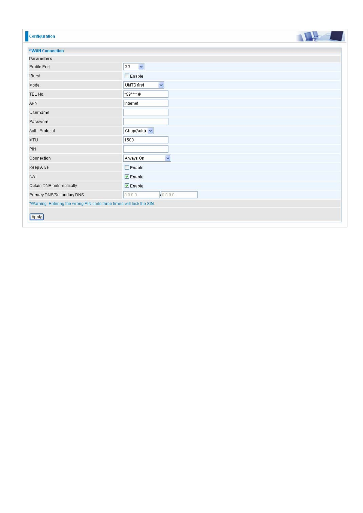
3G
Profile mode: select the profile port as 3G
iBurst: check the check box to determine whether to enable the iBurst function.
Mode: select your wanted mode of 3G operation from the drop-down menu.
TEL No.: The dial string to make a GPRS / 3G user internetworking call. It may provide by your
mobile service provider.
APN: An APN is similar to a URL on the WWW, it is what the unit makes a GPRS / UMTS call. The
service provider is able to attach anything to an APN to create a data connection, requirements for
APN’s to be assigned varies between different service providers. Most service providers have an
internet portal which they connect a DHCP Server to, giving you access to the internet i.e. Some
3G operators use the APN ‘internet’ for their portal. The default value of APN is “internet”.
Username: Enter the username provided by your service provider.
Password: Enter the password provided by your service provider.
Authentication Type: Default is None. Manually specify CHAP (Challenge Handshake
Authentication Protocol) or PAP (Password Authentication Protocol) if you know which type the
server is using (when acting as a client), or else the authentication type you want clients
connecting to you to use (when acting as a server). When using PAP, the password is sent
unencrypted, whilst CHAP encrypts the password before sending, and also allows for challenges at
different periods to ensure that an intruder has not replaced the client.
MTU: Maximum Transmission Unit. The size of the largest datagram (excluding media-specific
headers) that IP will attempt to send through the interface.
PIN: PIN stands for Personal Identification Number. A PIN code is a numeric value used in certain
systems as a password to gain access, and authenticate. In mobile phones a PIN code locks the
75
Page 80

SIM card until you enter the correct code. If you enter the PIN code incorrectly into the phone 3
times in a row, then the SIM card will be blocked and you will require a PUK code from your
network/service provider.
Connection: select the connection method you want.
Always On: The router will make UMTS/GPRS call when starting up. Enabling Always On,
will give you an option of Keep Alive.
Keep Alive: Set Enable to allow the router automatically reconnects the connection when
ISP disconnects it.
Connect to Demand: If you want to make UMTS/GPRS call only when there is a packet
requesting access to the Internet (i.e. when a program on your computer attempts to access the
Internet). In this mode, you must set Idle Timeout value at same time. Enabling Connect on
Demand will give you an option of Idle Timeout.
Idle Timeout: Auto-disconnect the connection when there is no activity on this call for a
predetermined period of time. The default value is 10 seconds.
NAT: The NAT (Network Address Translation) feature allows multiple users to access the Internet
through a single IP account, sharing the single IP address. If users on your LAN have public IP
addresses and can access the Internet directly, the NAT function can be disabled.
Obtain DNS: Select Automatic to use DNS.
Primary DNS/ Secondary DNS: Enter the IP addresses of the DNS servers. The DNS servers are
passed to the DHCP clients along with the IP address and the subnet mask.
Note: If you don’t know how to set these values and please keep them untouched.
76
Page 81

EWAN
Obtain an IP Address Automatically
Profile Port: Select the profile port as EWAN.
WAN Port: the router offers its Ethernet port 1 as a WAN port to be used to connect to Cable
Modems and fiber optic lines.
Protocol: Select Obtain an IP Address Automatically.
Obtain DNS: Select Automatic to use DNS.
Primary DNS/ Secondary DNS: Enter the IP addresses of the DNS servers. The DNS servers
are passed to the DHCP clients along with the IP address and the subnet mask.
77
Page 82
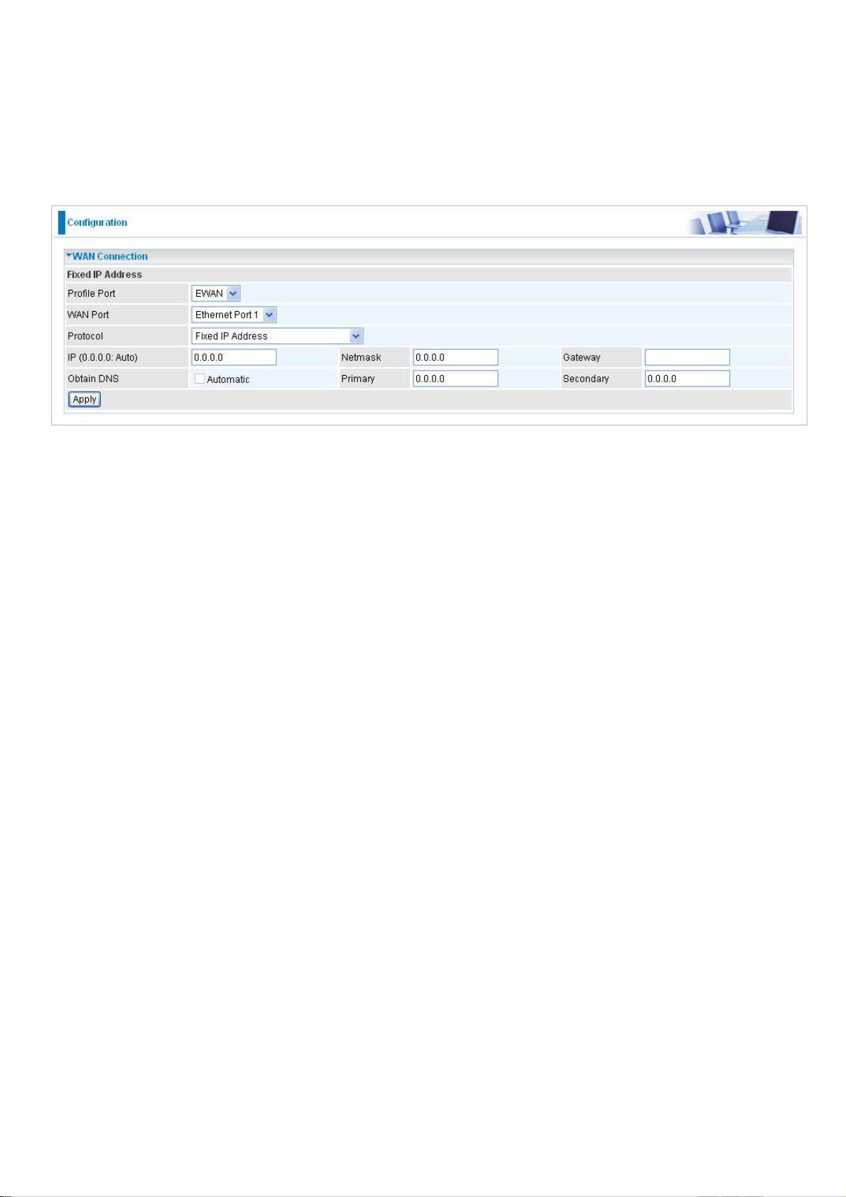
Fixed IP Address
Select this option to set static IP information. You will need to enter the Connection type, IP address,
netmask, and gateway address, provided to you by your ISP. Each IP address entered in the fields
must be in the appropriate IP form, which is four IP octets separated by a dot (x.x.x.x). The Router
will not accept the IP address if it is not in this format.
Profile Port: Select the profile port as EWAN.
WAN Port: the router offers its Ethernet port 1 as a WAN port to be used to connect to Cable
Modems and fiber optic lines.
Protocol: Select Fixed IP Address.
IP: Your WAN IP address. Leave this at 0.0.0.0 to automatically obtain an IP address from your
ISP.
Netmask: The default is 0.0.0.0. User can change it to other such as 255.255.255.0.Type the
netmask assigned to you by your ISP (if given).
Gateway: You must specify a gateway IP address (supplied by your ISP).
Obtain DNS: Select Automatic to use DNS.
Primary DNS/ Secondary DNS: Enter the IP addresses of the DNS servers. The DNS servers
are passed to the DHCP clients along with the IP address and the subnet mask.
78
Page 83

PPPoE
PPPoE (PPP over Ethernet) provides access control in a manner which is similar to dial-up
services using PPP.
Profile Port: Select the profile port as EWAN.
WAN Port: the router offers its Ethernet port 1 as a WAN port to be used to connect to Cable
Modems and fiber optic lines.
Protocol: Select PPPoE.
Username: Enter the username provided by your ISP. You can input up to 128 alphanumeric
characters (case sensitive). This is in the format of “username@ispname” instead of simply
“username”.
Password: Enter the password provided by your ISP. You can input up to 128 alphanumeric
characters (case sensitive).
Service Name: Enter a name for this connection.
IP: Your WAN IP address. Leave this at 0.0.0.0 to automatically obtain an IP address from your
ISP.
Auth. Protocol: Default is Auto. Your ISP advises on using Chap or Pap.
Connection:
Always on: If you want the router to establish a PPPoE session when starting up and to
automatically re-establish the PPPoE session when disconnected by the ISP.
Connect on Demand: If you want to establish a PPPoE session only when there is a packet
requesting access to the Internet (i.e. when a program on your computer attempts to access the
Internet).
Idle Timeout: Auto-disconnect the router when there is no activity on the line for a predetermined
period of time.
MTU: Maximum Transmission Unit. The size of the largest datagram (excluding media-specific
headers) that IP will attempt to send through the interface.
79
Page 84

MAC Spoofing: Select Enable and enter a MAC address that will temporarily change your router’s
MAC address to the one you have specified in this field. Leave it as Disabled if you do not wish to
change the MAC address of your router.
Obtain DNS: Select Automatic to use DNS.
Primary DNS/ Secondary DNS: Enter the IP addresses of the DNS servers. The DNS servers are
passed to the DHCP clients along with the IP address and the subnet mask
Pure Bridge
Profile Port: Select the profile port as EWAN.
WAN Port: the router offers its Ethernet port 1 as a WAN port to be used to connect to Cable
Modems and fiber optic lines.
Protocol: Select Pure Bridge.
Acceptable Frame Type: Specify which kind of traffic goes through this connection, all traffic or
only VLAN tagged.
Filter Type: Specify the type of Ethernet filtering performed by the named bridge interface.
All
Ip
PPPoE
Allows all types of ethernet packets through the port.
Allows only IP/ARP types of ethernet packets through the port.
Allows only PPPoE types of ethernet packets through the port.
80
Page 85

ADSL Mode
Connect Mode: This mode will automatically detect your ADSL line code, ADSL2+, ADSL2,
AnnexM2 and AnnexM2+, ADSL, All. Please keep the factory setting unless ADSL is detected as
the symptom of synchronization problem.
Modulation: It will automatically detect capability of your ADSL line mode. Please keep the
factory setting unless ADSL is detected as the symptom of synchronization problem.
Profile Type: Please keep the factory settings unless ADSL is detected as the symptom of low link
rate or unstable problems. You may need to change the profile setting to reach the best ADSL line
rate, it depends on the different DSLAM and location.
Activate Line: Aborting (false) your ADSL line and making it active (true) again for taking effect
with setting of Connect Mode.
Coding Gain: It reduces router’s transmit power which will effect to router’s downstream
performance. Higher the gain will increase the downstream rate but it sometimes causes unstable
ADSL line. The configurable ADSL coding gain is from 0 dB to 7dB, or automatic.
Tx Attenuation: It is the ADSL transmission power that the modem is using. The lower the power
the better performance in router’s upstream. Configurable value is between 0~12.
Elapsed Time: the time since ADSL connection is established.
81
Page 86

System
Here are the items within the System section: Time Zone, Remote Access, Firmware Upgrade,
Backup/Restore, Restart ,User Management and Mail Alert.
Time Zone
The router does not have a real time clock on board; instead, it uses the Simple Network Time
Protocol (SNTP) to get the current time from an SNTP server outside your network. Choose your
local time zone, click Enable and click the Apply button. After a successful connection to the Internet,
the router will retrieve the correct local time from the SNTP server you have specified. If you prefer
to specify an SNTP server other than those in the list, simply enter its IP address as shown above.
Your ISP may provide an SNTP server for you to use.
Daylight Saving is also known as Summer Time Period. Many places in the world adapt it during
summer time to move one hour of daylight from morning to the evening in local standard time. Check
Enable box to set your local time.
Resync Period (in minutes) is the periodic interval the router will wait before it re-synchronizes the
router’s time with that of the specified SNTP server. In order to avoid unnecessarily increasing the
load on your specified SNTP server you should keep the poll interval as high as possible – at the
absolute minimum every few hours or even days.
82
Page 87

Remote Access
To temporarily permit remote administration of the router (i.e. from outside your LAN), select a time
period the router will permit remote access for and click Enable. You may change other configuration
options for the web administration interface using Device Management options in the Advanced
section of the GUI.
If you wish to permanently enable remote access, choose a time period of 0 minute.
Firmware Upgrade
Your router’s “firmware” is the software that allows it to operate and provides all its functionality.
Think of your router as a dedicated computer, and the firmware as the software it runs. Over time
this software may be improved and revised, and your router allows you to upgrade the software it
runs to take advantage of these changes.
Clicking on Browse will allow you to select the new firmware image file you have downloaded to
your PC. Once the correct file is selected, click Upgrade to update the firmware in your router.
83
Page 88

Backup / Restore
These functions allow you to save and backup your router’s current settings to a file on your PC, or
to restore a previously saved backup. This is useful if you wish to experiment with different settings,
knowing that you have a backup handy in the case of any mistakes. It is advisable to backup your
router’s settings before making any significant changes to your router’s configuration.
Press Backup to select where on your local PC to save the settings file. You may also change the
name of the file when saving if you wish to keep multiple backups.
Press Browse to select a file from your PC to restore. You should only restore settings files that have
been generated by the Backup function, and that were created when using the current version of the
router’s firmware. Settings files saved to your PC should not be manually edited in any way.
After selecting the settings file you wish to use, pressing Restore will load those settings into the
router.
84
Page 89

Restart Router
Click Restart with option Current Settings to reboot your router (and restore your last saved
configuration).
If you wish to restart the router using the factory default settings (for example, after a firmware
upgrade or if you have saved an incorrect configuration), select Factory Default Settings to reset to
factory default settings.
You may also reset your router to factory settings by holding the small Reset pinhole button more
than 6 seconds on the back of your router.
Caution: After pressing the RESET button for more than 6 seconds, to be sure you power
cycle the device again.
85
Page 90
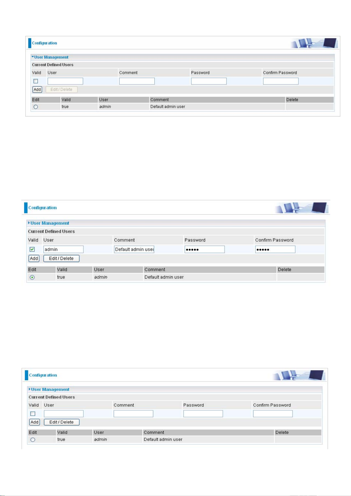
User Management
In order to prevent unauthorized access to your router’s configuration interface, it requires all users
to login with a password. You can set up multiple user accounts, each with their own password.
You are able to Edit existing users and Add new users who are able to access the device’s configuration
interface. Once you have clicked on Edit, you are shown the following options:
You can change the user’s password, whether their account is active and valid, as well as add a
comment to each user account. Click Edit/Delete button to save your revise. You cannot delete
the default admin account, if you do you will be log out. However, you can delete any other created
accounts by clicking Delete when editing the user. You are strongly advised to change the password
on the default “admin” account when you receive your router, and any time you reset your configuration
to Factory Defaults.
86
Page 91

When you create a user account, check Valid box and fill in the respective information for User,
Comment, Password and Confirm Password in the blanks provided. Then click the Add button to
add your new user account.
To delete a user account, click on the Delete radio button on the right column of the account you
wish to delete and then click the Edit/Delete button on the top to confirm your deletion.
87
Page 92

Mail Alert
Mail alert is designed to keep system administrator or other relevant personnels alerted of any
unexpected events that might have occured to the network computers or server for monitoring
efficiency. With this alert system, appropriate solutions may be tackled to fix problems that may
have arisen so that the server can be properly maintained.
SMTP Server: Enter the SMTP server that you would like to use for sending emails.
Username: Enter the username of your email account to be used by the SMTP server.
Password: Enter the password of your email account.
Sender’s Email: Enter your email address.
Recipient’s Email (Failover / Failback): Enter the email address that will receive the alert message
once a computer / network server failover occurs.
Recipient’s Email (WAN IP Change Alert): Enter the email address that will receive the alert
message once an WAN IP change has been detected.
88
Page 93

Firewall and Access Control
Your router includes a full SPI (Stateful Packet Inspection) firewall for controlling Internet access
from your LAN, as well as helping to prevent attacks from hackers. Besides, when using NAT, the
router acts as a “natural” Internet firewall, as all PCs on your LAN will use private IP addresses
that cannot be directly accessed from the Internet.
Firewall: Prevent outsiders from accessing your local network. The router provides three levels of
security support:
NAT natural firewall: This masks LAN users’ IP addresses which are invisible to users on the
Internet, thus making it more difficult for a hacker to target a machine on your network. This natural
firewall is turned on when NAT function is enabled.
Firewall Security and Policy (General Settings): Inbound direction of Packet Filter rules to
prevent unauthorized computers or applications to access your local network from the Internet.
Intrusion Detection: Enable Intrusion Detection to detect, prevent and log malicious attacks.
Access Control: Prevent access from PCs on your local network:
Firewall Security and Policy (General Settings): Outbound direction of Packet Filter rules to
prevent unauthorized computers or applications from accessing the Internet.
URL Filter: To block PCs on your local network from unwanted websites.
90
Page 94
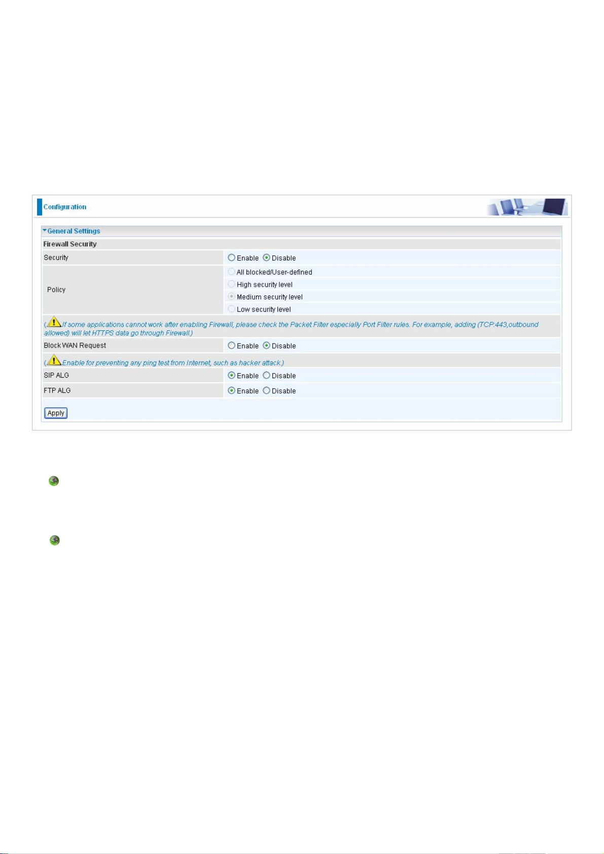
Listed are the items under the Firewall section: General Settings, Packet Filter, Intrusion Detection,
URL Filter, IM/P2P Blocking and Firewall Log.
General Settings
You can choose not to enable Firewall and still able to access to URL Filter and IM/P2P Blocking or
enable the Firewall using preset filter rules and modify the port filter rules as required. The Packet
Filter is used to filter packets based-on Applications (Port) or IP addresses.
There are four options when you enable the Firewall, they are:
All blocked/User-defined: no pre-defined port or address filter rules by default, meaning that
all inbound (Internet to LAN) and outbound (LAN to Internet) packets will be blocked. Users
have to add their own filter rules for further access to the Internet.
High/Medium/Low security level: the predefined port filter rules for High, Medium and Low
security are displayed in Port Filters of Packet Filter.
Select either High, Medium or Low security level to enable the Firewall. The only difference between
these three security levels is the preset port filter rules in the Packet Filter. Firewall functionality is
the same for all levels; it is only the list of preset port filters that changes between each setting. For
more detailed on level of preset port filter information, refer to Table 1: Predefined Port Filter.
If you choose of the preset security levels and add custom filters, this level of filter rules will be saved
even and do not need to re-configure the rules again if you disable or switch to other firewall level.
The “Block WAN Request” is a stand-alone function and not relate to whether security enable or
91
Page 95
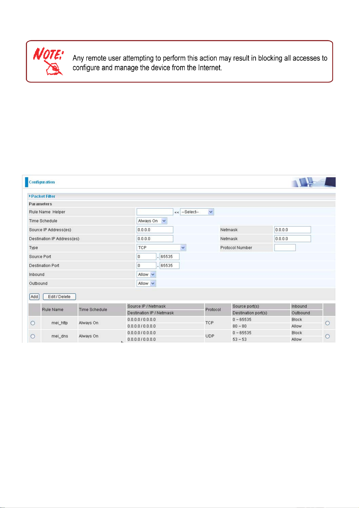
disable. Mostly it is for preventing any scan tools from WAN site by hacker.
Packet Filter
This function is only available when the Firewall is enabled and one of these four security levels is
chosen (All blocked, High, Medium and Low). The preset port filter rules in the Packet Filter must
modify accordingly to the level of Firewall, which is selected. See Table1: Predefined Port Filter for
more detail information.
92
Page 96

Example: Predefined Port Filters Rules
The predefined port filter rules for High, Medium and Low security levels are listed. See Table 1.
Note: Firewall – All Blocked/User-defined, you must define and create the port filter rules
yourself. No predefined rule is being preconfigured.
Table 1:
Predefined
Port Filter
Application
Protocol
Port
Number
Start End
HTTP(80) TCP(6) 80 80
DNS (53) UDP(17) 53 53
DNS (53) TCP(6) 53 53
FTP(21)
TCP(6) 21 21
Telnet(23) TCP(6) 23 23
SMTP(25) TCP(6) 25 25
POP3(110) TCP(6) 110 110 NO
Firewall - Low Firewall - Medium Firewall – High
Inbound Outbound Inbound
NO
NO
NO
NO
NO
NO
YES
YES
YES
YES
YES
YES
YES
NO
NO
NO
NO
NO
NO
NO
Outbound
YES
YES
YES
YES
YES
YES
YES
Inbound Outbound
NO
NO
NO
NO
NO
NO
NO
YES
YES
YES
NO
NO
YES
YES
NEWS(NNTP)
(Network
News Transfer
TCP(6)
119
119
Protocol)
RealAudio/
RealVideo
UDP(17)
7070
7070
YES
(7070)
PING
ICMP(1) N/A N/A NO
H.323(1720) TCP(6) 1720 1720 YES
T.120(1503) TCP(6) 1503 1503 YES
SSH(22)
TCP(6) 22 22
NTP /SNTP UDP(17) 123 123 NO
HTTP/HTTP
Proxy (8080)
TCP(6) 8080 8080 NO
HTTPS(443) TCP(6) 443 443 NO
ICQ (5190) TCP(6) 5190 5190 YES
MSN (1863) TCP(6) 1863 1863 YES
MSN (7001) UDP(17) 7001 7001 YES
NO
NO
YES
YES
YES
YES
YES
YES
YES
YES
YES
YES
YES
YES
NO
YES
NO
NO
NO
NO
NO
NO
NO
N/A
N/A
N/A
YES
YES
YES
YES
YES
YES
YES
NO
YES
N/A
N/A
N/A
NO
NO
NO
NO
NO
NO
NO
NO
N/A
N/A
N/A
N/A
NO
NO
YES
NO
NO
NO
YES
NO
N/A
N/A
N/A
N/A
MSN VEDIO
(9000)
TCP(6) 9000 9000 NO
YES
93
N/A
N/A
N/A
N/A
Page 97

Inbound: Internet to LAN
Outbound: LAN to Internet
YES: Allowed
NO: Blocked
N/A: Not Applicable
Packet Filter – Add TCP/UDP Filter
Rule Name Helper: Users-define description to identify this entry or click “Select” drop-down
menu to select existing predefined rules. The maximum name length is 32 characters.
Time Schedule: It is self-defined time period. You may specify a time schedule you’re your
prioritization policy. For setup and detail, refer to Time Schedule section
Source IP Address(es) / Destination IP Address(es): This is the Address-Filter used to allow or
block traffic to/from particular IP address(es). Selecting the Subnet Mask of the IP address range
you wish to allow/block the traffic to or form; set IP address and Subnet Mask to 0.0.0.0 to inactive
the Address-Filter rule.
Tip: To block access, to/from a single IP address, enter that IP address as the Host IP Address
and use a Host Subnet Mask of “255.255.255.255”.
Type: It is the packet protocol type used by the application, select TCP, UDP or both TCP/UDP.
Protocol Number: Insert the port number.
Source Port: This Port or Port Ranges defines the port allowed to be used by the Remote/WAN to
connect to the application. Default is set from range 0 ~ 65535. It is recommended that this option
be configured by an advanced user.
Destination Port: This is the Port or Port Ranges that defines the application.
Inbound / Outbound: Select Allow or Block the access to the Internet (“Outbound”) or from the
Internet (“Inbound”).
Click Add button to apply your changes.
94
Page 98

Packet Filter – Add Raw IP Filter
Go to “Type” drop-down menu, select “Use Protocol Number”.
Rule Name Helper: Users-define description to identify this entry or choosing “Select” drop-down
menu to select existing predefined rules.
Time Schedule: It is self-defined time period. You may specify a time scheduleyou’re your
prioritization policy. For setup and detail, refer to Time Schedule section
Source IP Address(es) / Destination IP Address(es): This is the Address-Filter used to allow or
block traffic to/from particular IP address(es). Selecting the Subnet Mask of the IP address range
you wish to allow/block the traffic to or form; set IP address and Subnet Mask to 0.0.0.0 to inactive
the Address-Filter rule.
Tip: To block access, to/from a single IP address, enter that IP address as the Host IP
Address and use a Host Subnet Mask of “255.255.255.255”.
Type: It is the packet protocol type used by the application, select TCP, UDP or both TCP/UDP.
Protocol Number: Insert the port number, i.e. GRE 47.
Source Port: This Port or Port Ranges defines the port allowed to be used by the Remote/WAN to
connect to the application. Default is set from range 0 ~ 65535. It is recommended that this option
be configured by an advanced user.
Destination Port: This is the Port or Port Ranges that defines the application.
Inbound / Outbound: Select Allow or Block the access to the Internet (“Outbound”) or from the
Internet (“Inbound”).
Click the Add button to apply your changes.
Example: Configuring your firewall to allow a publicly accessible web server on your LAN
The predefined port filter rule for HTTP (TCP port 80) is the same no matter whether the firewall is
set to a high, medium or low security level. To setup a web server located on the local network when
the firewall is enabled, you have to configure the Port Filters setting for HTTP.
95
Page 99
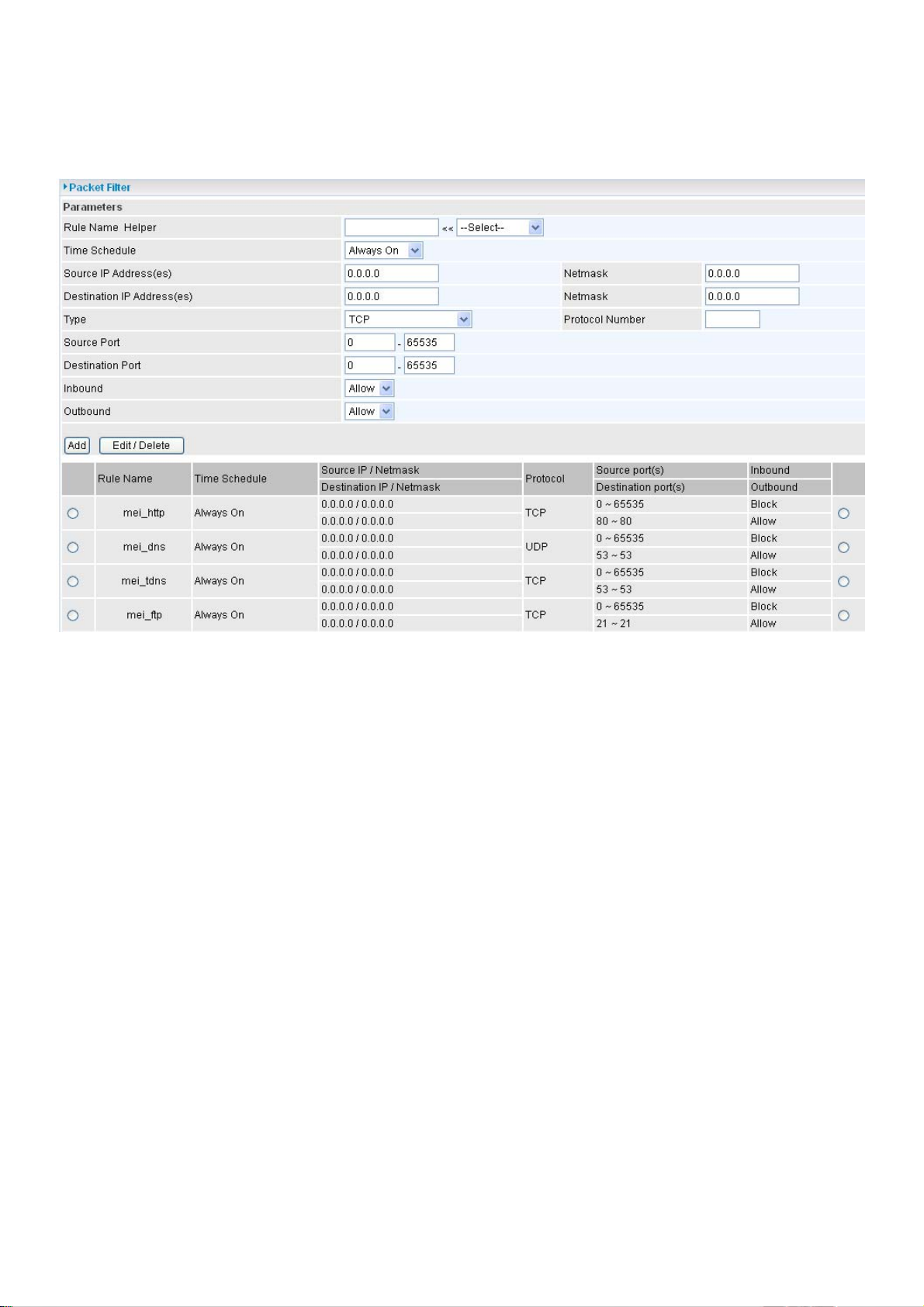
As you can see from the diagram below, when the firewall is enabled with one of the three presets
(Low/Medium/High), inbound HTTP access is not allowed which means remote access through
HTTP to your router is not allowed.
Note: Inbound indicates accessing from Internet to LAN and Outbound is from LAN to the
Internet.
96
Page 100

Configuring Packet Filter:
1. Click Packet Filters. You will then be presented with the predefined port filter rules screen (in
this case for the low security level), shown below:
Note: Y ou may click Edit the predefined rule instead of Delete it. This is an example to show
to how you add a filter on your own.
2. Choose the radio button you want to delete the existing HTTP rule. Click Edit/Delete button to
delete the existing HTTP rule.
3. Input the Rule Name, Time Schedule, Source/Destination IP, Type, Source/Destination Port,
Inbound and Outbound.
97
 Loading...