


XLT-1571AC
Table of contents
 Loading...
Model XLT-1571AC
Operation and
Maintenance Manual
`
AERIAL WORK PLATFORMS
R
Electric Hydraulic Lift Platform
WA
R
NIN
G
XLT
1
5
7
1
WA
R
N
IN
G
D
ANGER
W
ARNING
W
A
RNING
B33-01-0062

TELESCOPIC PERSONNEL LIFT
This equipment is designed and manufactured in compliance with the duties, re-
sponsibilities, and standards set forth for manufacturers in the ANSI 92.3 standard
in effect at the time of manufacture.
This equipment will meet or exceed applicable OSHA codes and ANSI A92.3 stan-
dards when used in accordance with sections 5, 6, 7, 8, 9 & 10 of ANSI A92.3 and all
other manufacturer’s recommendations.
It is the responsibility of the user of this equipment to follow all applicable ANSI,
OSHA, Federal, State, and local codes and regulations that govern the safe opera-
tion of this equipment.

i
Table of Contents
1 Safety................................................................................................................1-1
1-1 Introduction.........................................................................................1-1
1-2 Before Operation ...............................................................................1-3
1-3 During Operation................................................................................1-4
1-4 Maintenance Safety............................................................................ 1-6
1-5 Damaged Equipment Policy .............................................................1-6
2 Introduction.....................................................................................................2-1
2-1 General Description...........................................................................2-1
2-2 Specifications......................................................................................2-2
2-3 Warranty.............................................................................................2-2
3 Operation.........................................................................................................3-1
3-1 Operator Controls ..............................................................................3-1
3-2 Normal Operating Procedure............................................................3-2
3-3 Emergency Lowering Procedure ......................................................3-3
4 Maintenance ....................................................................................................4-1
4-1 Scheduled Service Checks................................................................4-1
4-2 Lubrication..........................................................................................4-3
4-3 Hydraulic System...............................................................................4-5
4-4 Electrical System .............................................................................4-11
4-5 Lift Chains And Slide Blocks.......................................................4-12
4-6 Troubleshooting................................................................................4-15
5 Replacement Decals ........................................................................................5-1
6 Parts List..........................................................................................................6-1
6-1 Top Mast Parts List..........................................................................6-2
6-2 Center Mast Parts List......................................................................6-4
6-3 Lower Mast Parts List......................................................................6-6
6-4 Rear Compartment Parts List............................................................6-8
6-5 Hydraulic Pump Compartment Parts List.....................................6-10
6-6 Upper Base Parts List ....................................................................6-12
6-7 Base Mast Parts List ......................................................................6-14
6-8 Lower Base Parts List....................................................................6-16
6-9 Platform Parts List..........................................................................6-18
6-10 Hydraulic Unit Parts List...............................................................6-20
6-11 Hydraulic Fittings And Hoses Diagram............................................6-22
6-12 Hydraulic Fittings And Hoses Schematic.....................................6-24
6-13 Electrical Diagram...........................................................................6-25
7 ANSI Reprint..................................................................................................7-1

ii
List of Illustrations
Figure 3-1. Lower Control Box................................................................................. 3-1
Figure 3-2. Upper Control Box................................................................................. 3-2
Figure 3-3. Emergency Lowering Valve................................................................... 3-3
Figure 4-1. Lift Chain Lubrication............................................................................ 4-3
Figure 4-2. Caster Lubrication.................................................................................. 4-4
Figure 4-3. Pressure Relief Valve Adjustment.......................................................... 4-6
Figure 4-4. Flow Restrictor Valve ............................................................................ 4-7
Figure 4-5. Raise Valve Operation Check ................................................................ 4-8
Figure 4-6. Hydraulic Cylinder Exploded View..................................................... 4-10
Figure 4-7. Chain Elongation Inspection................................................................ 4-12
Figure 4-8. Lift Chain Adjustment.......................................................................... 4-13
Figure 4-9. Slide Block Adjustment........................................................................ 4-14
Figure 5-1. Replacement Decals............................................................................... 5-2
Figure 5-2. Decal Locations, Side View................................................................... 5-3
Figure 5-3. Decal Locations, Front View.................................................................. 5-4
Figure 6-1. Top Mast Exploded View....................................................................... 6-2
Figure 6-2. Center Mast Exploded View .................................................................. 6-4
Figure 6-3. Lower Mast Exploded View................................................................... 6-6
Figure 6-4. Rear Compartment Exploded View........................................................ 6-8
Figure 6-5. Hydraulic Pump Compartment Exploded View................................... 6-10
Figure 6-6. Upper Base Exploded View................................................................. 6-12
Figure 6-7. Base Mast Exploded View ................................................................... 6-14
Figure 6-8. Lower Base Exploded View ................................................................. 6-16
Figure 6-9. Platform Exploded View...................................................................... 6-18
Figure 6-10. Hydraulic Unit Assembly..................................................................... 6-20
Figure 6-11. Hydraulic Fittings and Hoses Diagram ................................................ 6-22
Figure 6-12. Hydraulic Fittings and Hoses Schematic.............................................. 6-24
Figure 6-13. Electrical Diagram................................................................................ 6-25
Figure 6-14. Electrical Layout Diagram ................................................................... 6-26

iii
List of Tables
Table 1-1. Minimum Safe Approach Distances .......................................................1-4
Table 2-1. Specifications..........................................................................................2-2
Table 4-1. Daily/Weekly Service Checks.................................................................4-1
Table 4-2. Monthly Service Checks.........................................................................4-2
Table 4-3. Troubleshooting Chart ..........................................................................4-15
Table 5-1. Replacement Decals................................................................................5-1
Table 6-1. Top Mast Parts List.................................................................................6-3
Table 6-2. Center Mast Parts List.............................................................................6-5
Table 6-3. Lower Mast Parts List.............................................................................6-7
Table 6-4. Battery Compartment Parts List..............................................................6-9
Table 6-5. Hydraulic Pump Compartment Parts List .............................................6-11
Table 6-6. Upper Base Parts List............................................................................6-13
Table 6-7. Base Mast Parts List..............................................................................6-15
Table 6-8. Lower Base Parts List ...........................................................................6-17
Table 6-9. Platform Parts List.................................................................................6-19
Table 6-10. Hydraulic Unit Parts List ......................................................................6-21
Table 6-11. Hydraulic Fittings and Hoses Parts List................................................6-23
Table 7-1. Minimum Safe Approach Distance (M.S.A.D.) to energized
(exposed or insulated) power lines and parts....................................7-11

iv

1-1
1
Safety
1-1
ip-
me-
sense in the operation of mechanical equipment is the best
s
e implemented at all
considered as legal advice and is intended
to
For any questions concerning the safe use of this equipment, call 800-537-0540 before
operating.
INTRODUCTION
Familiarity and proper training are required for the safe operation of mechanical equ
ment. Equipment operated improperly or by untrained personnel can be dangerous. Read
the operating instructions in this manual and become familiar with the location and
proper use of all controls. Inexperienced operators should receive instruction from so
one familiar with the equipment before being allowed to operate the machine. The use of
intelligence and common
practice in any safety policy. Be professional and always observe the safety procedure
set forth in this manual.
All OSHA, ANSI, state and local codes and regulations pertaining to this equipment
should be obtained, read, and thoroughly understood before attempting to operate this
equipment. Persons under the influence of drugs, alcohol, or prescription medication
should not be on or near this equipment. Common sense should b
times during the use of this equipment. Do not operate this equipment in areas where
equipment or user may come in contact with live power source.
The information contained herein is not to be
for informational purposes only. This information is offered to alert Bil-Jax customers
procedures that may be of concern to them.
This information is not intended to be all inclusive and is to b e followed in the use of
Bil-Jax equipment only.
XLT-1571AC
1-2
Safety Notes
This manual contains DANGERS, WARNINGS, CAUTIONS, and NOTES that must be
followed to prevent the possibility of improper service, damage to the equipment, or per-
sonal injury.
DANGER
Dangers warn of equipment operation near electrical power lines that could lead
to personal injury or death.
WARNING
Warnings describe conditions or practices that could lead to personal injury or
death.
CAUTION
Cautions provide information important to prevent errors that could damage ma-
chine or components.
NOTE: Notes contain additional information important to a procedure.

1 — SAFETY
1-3
1-2 BEFORE OPERATION
Ensure the following general safety precautions are followed before operating the Cougar
Lift.
• ALWAYS survey the usage area for potential hazards such as untampered earth
fills, unlevel surfaces, overhead obstructions, and electrically charged conduc-
tors or wires. Be aware of any potential hazards and always consider what could
happen. Watch for moving vehicles in the operating area.
• ALWAYS read, understand, and follow the procedures in this manual before at-
tempting to operate equipment.
• ALWAYS inspect the equipment for damaged or worn parts. Check for cracked
welds, hydraulic leaks, damaged wiring, loose wire connectors, damaged cast-
ers, and damaged floor pads. Also check for any improper operation. NEVER
operate equipment if damaged in any way. Improperly operating equipment
must be repaired before using.
• ALWAYS wear proper clothing for the job. Wear protective equipment as re-
quired by federal, state, or local regulations.
• ALWAYS locate, read, and follow all directions and warnings displayed on the
equipment.
• ALWAYS inspect the equipment for any “DO NOT USE” tags placed on the
equipment by maintenance personnel. NEVER use any equipment tagged in this
way until repairs are made and all tags are removed by authorized maintenance
personnel.
• ALWAYS make sure the platform and shoes are free of mud, grease, or other
foreign material. This will reduce the possibility of slipping.
• NEVER allow improperly trained personnel to operate this equipment. Only
trained and authorized personnel shall be allowed to operate this equipment.
• NEVER operate this equipment if you are under the influence of alcohol or
drugs or if you feel ill, dizzy, or unsteady in any way. Operators must be physi-
cally fit, thoroughly trained, and not easily excitable.
• NEVER modify, alter, or change the equipment in any way that would affect its
original design or operation in any way.
• NEVER operate this equipment in ways for which it is not intended.
XLT-1571AC
1-4
1-3 DURING OPERATION
Ensure the following general safety precautions are followed during the operation of the
Cougar Lift.
DANGER
This machine is not insulated for use near electrical power lines and DOES NOT
provide protection from contact with or close proximity to any electrically
charged conductor. Operator must maintain safe clearances at all times (10 feet
minimum) and always allow for platform movement such as wind induced sway.
Always contact the power company before performing work near power lines. As-
sume every line is hot. Remember, power lines can be blown by the wind.
Refer to Table 1-1 for minimum safe approach distances between machine and electrical
power lines.
Table 1-1. Minimum Safe Approach Distances
Minimum Safe Approach Distance
Voltage Range
(Phase to Phase)
(Feet) (Meters)
0 to 300V Avoid Contact
Over 300V to 50KV 10 3.05
Over 50KV to 200KV 15 4.60
Over 200KV to 350KV 20 6.10
Over 350KV to 500KV 25 7.62
Over 500KV to 750KV 35 10.67
Over 750KV to 1000KV 45 13.72
• ALWAYS position lift far enough away from power sources to ensure that no
part of the lift can accidentally reach into an unsafe area.
• ALWAYS operate only on a firm and level surface. NEVER use on surfaces
that do not support the weight of the equipment and its rated load capacity.
• ALWAYS keep yourself and all personnel away from potential pinch or shear
points.
• ALWAYS report any misuse of equipment to the proper authorities. Horseplay
is prohibited.
• ALWAYS maintain good footing on the platform. NEVER wear slippery soled
shoes.
• ALWAYS make certain all personnel are clear and there are no obstructions be-
fore repositioning platform.
• ALWAYS cordon off area around the base to keep personnel and other equip-
ment away from it while in use.
• ALWAYS stay clear of wires, cables, and other overhead obstructions.
• ALWAYS disconnect power at the batteries when not in use to guard against
unauthorized use.

1 — SAFETY
1-5
• NEVER allow electrode contact with any part of the platform if welding is be-
ing performed by a worker from the platform.
• NEVER use without the floor pads fully based on the floor.
• NEVER override or by-pass manufacturer's safety devices.
• NEVER release floor locks or move unit with a person or materials on board.
• NEVER stand or sit on guardrails. Work only within the platform guardrail area
and do not lean out over guardrails to perform work.
• NEVER attempt to increase working height with boxes, ladders, or other means.
• NEVER operate this equipment when exposed to high winds, thunderstorms,
ice, or any other weather conditions that would compromise the safety of the
operator.
• NEVER climb up or down masts.
• NEVER allow ropes, electric cords, hoses, etc. to become entangled in the
equipment when the platform is being raised or lowered.
• NEVER exceed manufacturer's platform load limits and make sure all materials
are evenly distributed over the entire platform.
• NEVER exceed platform load ratings by transferring loads to platform at ele-
vated heights.
• NEVER use guardrails to carry materials and never allow overhang of materials
when raising or lowering platform.

XLT-1571AC
1-6
1-4 MAINTENANCE SAFETY
Ensure the following general safety precautions are observed when maintenance is per-
formed on the Cougar Lift.
• ALWAYS perform maintenance procedures according to manufacturer's re-
quirements. NEVER short change maintenance procedures.
• ALWAYS check hydraulic system. Make sure all lines, connectors, and fittings
are tight and in good condition.
• ALWAYS keep all mechanisms properly adjusted and lubricated according to
maintenance schedule and manufacturers specifications.
• ALWAYS perform a function check of operating controls before each use and
after repairs have been made.
• ALWAYS locate and protect against possible pinch points prior to performing
maintenance and repairs.
• ALWAYS use only factory approved parts to repair or maintain this equipment.
If this equipment is rebuilt, retesting is required in accordance with factory in-
structions.
• NEVER add unauthorized fluids to the hydraulic system or battery. Check
manufacturers specifications.
• NEVER exceed the manufacturer's recommended relief valve settings.
• NEVER attempt repairs you do not understand. Consult manufacturer if you
have any questions regarding proper maintenance, specifications, or repair.
1-5 DAMAGED EQUIPMENT POLICY
Safety Statement
At Bil-Jax, we are dedicated to the safety of all users of our products. Therefore, all
Bil-Jax lifts are designed, manufactured and tested to comply with current applicable
Federal OSHA and ANSI codes and regulations.
Damage Policy
There may be occasions when a Bil-Jax lift is involved in an incident that results in struc-
tural damage to the lift. This can seriously compromise the ability of the lift to perform in
a safe manner. Therefore, whenever a Bil-Jax lift is damaged structurally or when there is
the possibility of structural damage (this damage may be internal and is not always visi-
ble to the naked eye), Bil-Jax requires that the lift be returned to our facility at 125 Tay-
lor Parkway, Archbold, Ohio, for reconditioning. If you have any questions concerning
what constitutes structural damage, please call the Bil-Jax Service Department at
800-537-0540.
Damage Repair Notice
There may be occasions when a Bil-Jax lift is involved in an incident resulting in non-
structural damage. When this occurs and repairs are made by the owner or area distribu-
tor, please notify Bil-Jax of these non-maintenance repairs and request a repair form to
be filled out and returned to Bil-Jax.

2-1
2
Introduction
2-1
mits the operator to
ic
e
is raised three inches for each one inch of
oaded to approximately 0.6 feet per
orrode dur-
Carefully read all the safety instructions contained in Section 1 of this manual before op-
erating the Cougar Lift.
GENERAL DESCRIPTION
The model XLT-1571 Cougar Lift is designed and manufactured for use as a warehouse
stocking and order picking machine. Its unique guard rail design per
ride on the platform with the load, while transferring it from group level to its overhead
storage location. The maximum platform load is limited to 500 lbs.
Platform elevation is accomplished by means of a 1-1/2 inch displacement type hydraul
cylinder. The lower telescoping section is pushed vertically upward by the cylinder whil
the upper sections are raised by a mechanical motion advantage accomplished through
two sets of chains and sheaves. The platform
cylinder extension. Platform elevation and descent is controlled by pushbuttons on the
upper control box located on the platform.
Safety of operation is assured by proper inspection and maintenance procedures as set
forth in this manual. The possibility of platform free-fall is eliminated by proper mainte-
nance and replacement of the chains, sheaves and sheave pins, a properly installed flow
restrictor valve, and a clean mast. The non-adjustable restrictor valve controls and fixes
the rate of platform descent whether empty or fully l
second. A hydraulic hose failure will result in the same rate of descent, eliminating free-
fall, when the restrictor valve is installed properly.
Emergency lowering of the platform is accomplished by means of a manual control valve
located on the hydraulic manifold block assembly, next to the pump/motor unit.
The Cougar Lift features a displacement type of cylinder that will not rust or c
ing storage since the cylinder rod is immersed in oil. It is important that the cylinder rod
be kept clean and undamaged for the protection of the cylinder head packing.
The floor lock safety switch prevents the unit from raising until th e two floor pads have
been properly engaged and helps to make the Cougar Lift a safe, dependable machine.

XLT-1571AC
2-2
2-2 SPECIFICATIONS
Cougar Lift Electric Hydraulic Lift Platform
Model Number XLT-1571AC Serial Number ________________
Manufactured by: Bil-Jax, Inc.
125 Taylor Parkway
Archbold, Ohio 43502
800-537-0540
Table 2-1. Specifications
Rated Platform Load 500 lbs (227 kg) total including operator [1 person +
materials not to exceed 500 lbs (227 kg)]
Extended Platform Height 14 ft-10 in. (4.5 m)
Retracted Platform Height 18-1/2 in. (0.47 m)
Platform Dimensions 29 in. w x 50 in. l x 42 in. h
(0.74 m x 1.27 m x 1.07 m)
Base Dimensions 30-1/2 in. w x 71 in. l x 77 in. h
(0.77 m x 1.8 m x 1.95 m)
Retracted Dimensions 30-1/2 in. w x 73-1/2 in. l x 77 in. h
(0.77 m x 1.87 m x 1.95 m)
Gross Shipping Weight 1025 lbs (465 kg)
Full Extension Time 20 seconds empty, 32 seconds loaded
Complete Retraction Time 22 seconds empty, 22 seconds loaded
Platform Extension Rate 0.66 ft (0.3 m)/sec. empty
0.42 ft (0.19 m)/sec. loaded
Hydraulic System Pressure 1200 psi empty, 2100 psi loaded
Power Source 110VAC, 60 Hz
2-3 WARRANTY
Bil-Jax warrants its telescopic lifts for three years from the date of delivery against all
defects of material and workmanship, provided the unit is operated and maintained in
compliance with Bil-Jax’s operating and maintenance instructions. Bil-Jax will, at its
option, repair or replace any unit or component part which fails to function properly in
normal use.
This warranty does not apply if the lift and/or its component parts have been altered,
changed, or repaired without the consent of Bil-Jax or by anyone other than Bil-Jax or its
factory trained personnel, nor if the lift and/or its components have been subjected to
misuse, negligence, accident or any conditions deemed other than those considered as
occurring during normal use.
Components not manufactured by Bil-Jax, are covered by their respective manufacturers
warranties. A list of those components and their warranties is available upon written
request to Bil-Jax.
Bil-Jax shall not in any event be liable for the cost of any special, indirect or
consequential damages to anyone, product, or thing. This warranty is in lieu of all other
warranties expressed or implied. We neither assume nor authorize any representative or
other person to assume for us any other liability in connection with the sale, rental, or use
of this product.
3-1
3
Operation
3-1
The operator controls for the Cougar Lift are contained on the upper and lower control
/BASE ROLLS, and WHEEL UP/BASE
SET
. The controls on the lower control box are used to set the unit in proper position be-
OPERATOR CONTROLS
boxes.
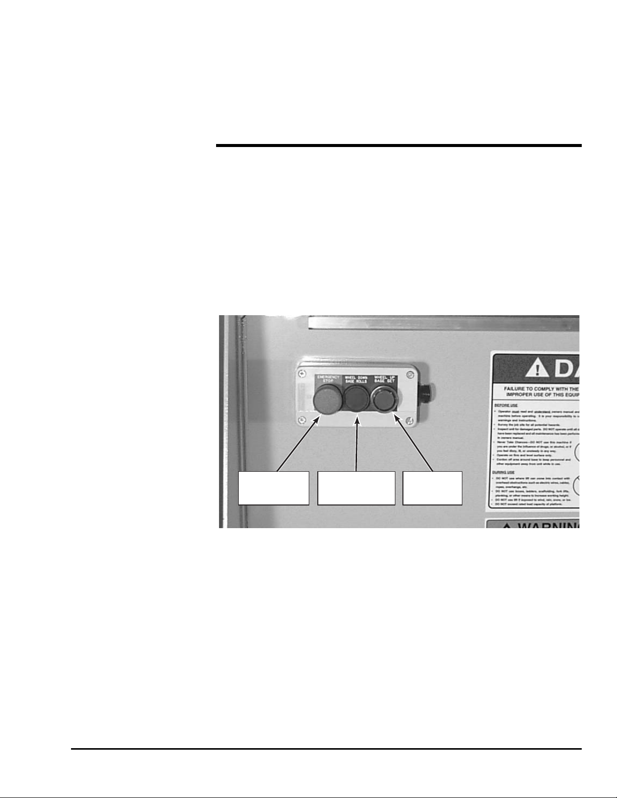
Lower Control Box
The lower control box is located on the front of the base platform and contains 3
pushbutton controls,
EMERGENCY STOP, WHEEL DOWN
fore the platform can be raised. Refer to Figure 3-1.
EMERGENCY
STOP
BUTTON
WHEEL DOWN
BASE ROLLS
BUTTON
WHEEL UP
BASE SET
BUTTON
Figure 3-1. Lower Control Box
XLT-1571AC
3-2
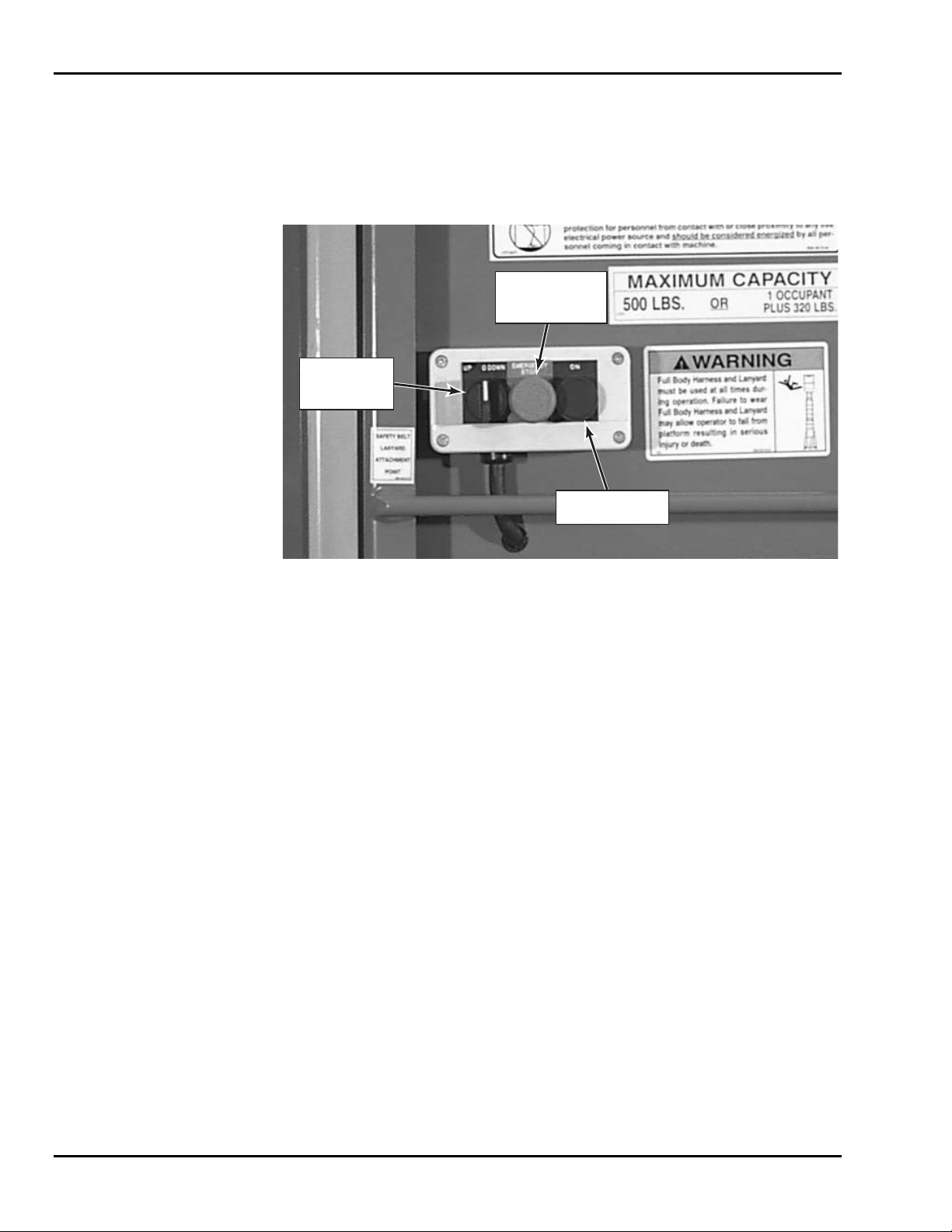
Upper Control Box
The upper control box is located on the back of the top mast and is accessible from the
platform. The upper control box contains 3 controls,
UP/DOWN selector switch,
EMERGENCY STOP pushbutton, and ON pushbutton. The controls on the upper control box
are used to raise and lower the unit. Refer to Figure 3-2.
UP/DOWN
SELECTOR
SWITCH
EMERGENCY
STOP
PUSHBUTTON
ON
PUSHBUTTON
Figure 3-2. Upper Control Box
3-2 NORMAL OPERATING PROCEDURE
Perform the following procedures to operate the Cougar Lift.
1. Read and follow all safety precautions contained in Section 1 and all responsi-
bilities outlined in the ANSI A92.3 reprint contained in Section 7 of this man-
ual.
2. Position the lift at the work area. Make sure the lift is on a firm and level surface
and that there are no potential hazards such as overhead obstructions or electri-
cally charged conductors. Do not operate the lift if such hazards exist.
3. Check the lift for damaged or worn parts and repair or replace as necessary.
4. Check to be sure that the platform is properly attached to the lift.
5. Raise the casters located under the platform by depressing the
WHEEL UP/BASE
SET
pushbutton located on the lower control box. Raising the casters allows the
base to set firmly on the two foot pads.
6. The lift should be level and positioned on the two foot pads with the
WHEEL
UP
/BASE SET pushbutton lit green. Ensure that the platform's upward path of
travel is free from obstructions. Reposition the lift if necessary.
NOTE: The lift is equipped with a level sensor that will prevent the lift from rais-
ing if the lift is at a slope greater than 1 degree. The green
WHEEL
UP
/BASE SET pushbutton will no longer illuminate until the lift is re-
leveled.
7. Enter the platform. Ensure that both side midrails are positioned properly.
3 — OPERATION
3-3
8. The lift is now ready for operation. While depressing the ON pushbutton, select
the desired function,
UP or DOWN on the position selector switch. The platform
will raise or lower respectively. The
EMERGENCY STOP pushbutton deactivates
the control circuit.
NOTE: Should the platform continue to rise after the UP switch is released, press
the
ON pushbutton and select the DOWN position at the same time and the
platform should stop or lower.
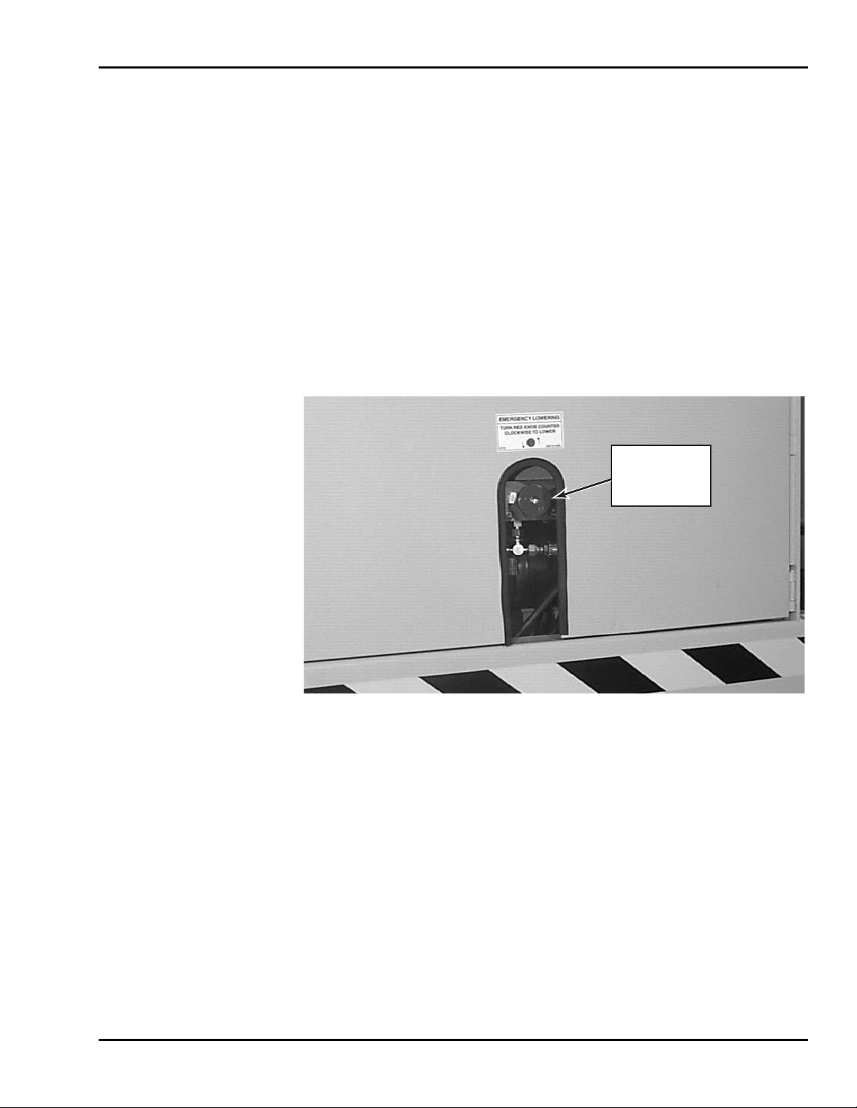
3-3 EMERGENCY LOWERING PROCEDURE
The Cougar Lift is equipped with a manual lowering valve in case of emergency situa-
tions to lower the platform. The emergency lowering valve is located on the hydraulic
block manifold in the hydraulic pump compartment. The valve may be accessed through
the opening on the base door. To lower the platform, turn the red knob on the valve
counterclockwise. Refer to Figure 3-3.
EMERGENCY
LOWERING
VALVE
RED KNOB
Figure 3-3. Emergency Lowering Valve

XLT-1571AC
3-4

4-1
4
Maintenance
4-1 HECKS
Perform the following -1.
/Weekly Service Chec
D
before use Weekly
SCHEDULED SERVICE C
Daily/Weekly Service Checks
daily/weekly service checks as listed in Table 4
Table 4-1. Daily ks
Service Check
aily
Ensure Operation Manual is located in manual tube.
Check chain assemblies for split leaves,
excessive wear, or elongation.
loose pins,
Check and retighten all nuts and bolts.
Check cage attachment to the platform is secure and that th
cage side midrails slide freely.
e
Check to be sure slide blocks and their path are clean and
t.
lightly lubricated with a silicone lubrican
Check level sensor.
Check to see that all decals are present.
Check that all functions at lower and upper control bo
are operating properly.
xes
Check for wear on chain sheaves, sheave axles, and
bearings.
Lubricate chains with 40W oil.
Check casters for wear on axles and swivel raceways.
Check surface of casters for cracks or excessive wear.
XLT-1571AC
4-2
Monthly Service Checks
Perform the following monthly service checks as listed in Table 4-2.
Table 4-2. Monthly Service Checks
Service Check
Every
month
Every
6 months
Every
12 months
Every
48 months
Check hydraulic raise valve
operation.
Check operation of manual
emergency lowering valve.
Lubricate caster swivels and
axles.
Replace hydraulic oil.
Check slide blocks for wear.
Check for mast sway.
Load test with 500 pounds.
Replace lift chains.
4 — MAINTENANCE
4-3
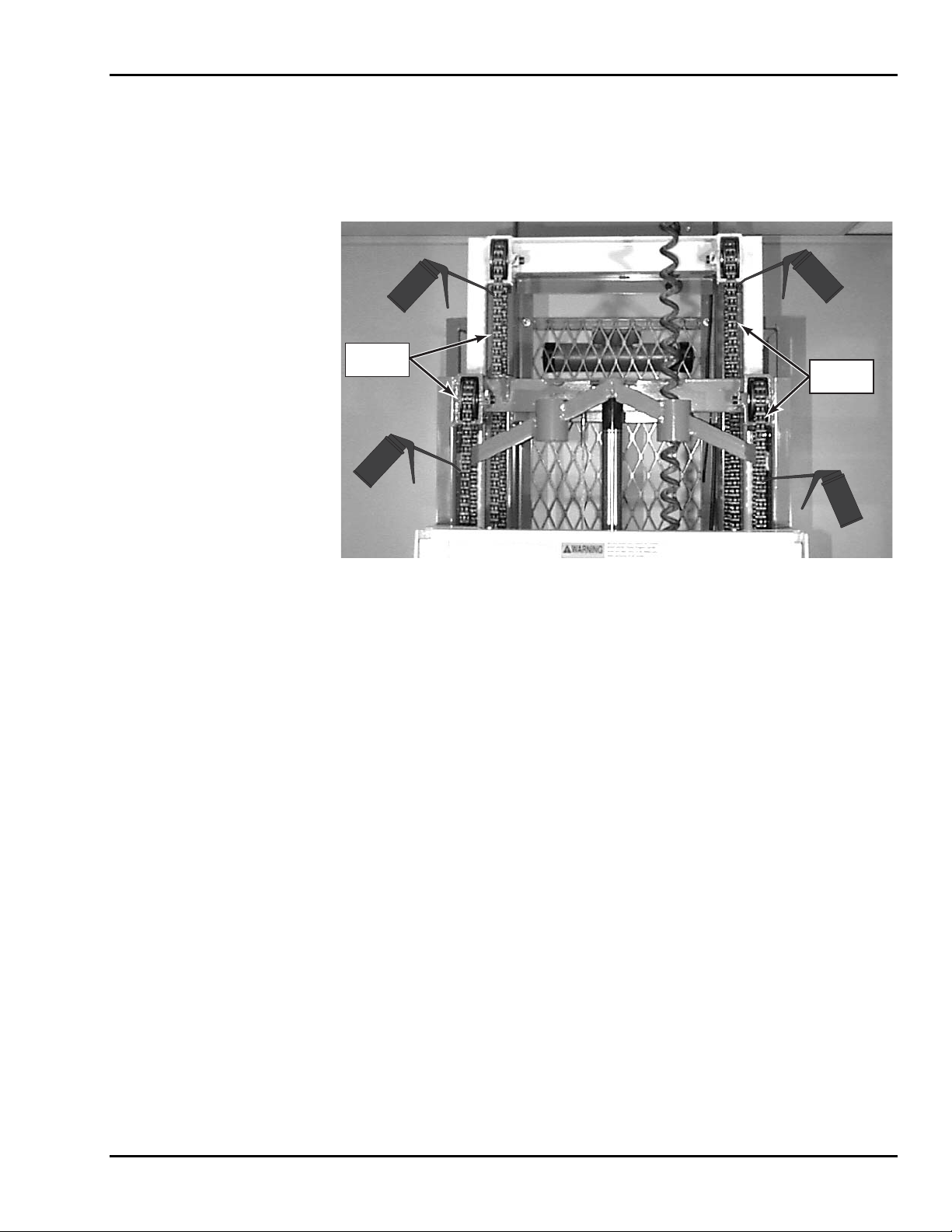
4-2 LUBRICATION
Lubrication makes operation of the Cougar Lift more efficient and extends the life of the
unit. Perform the following lubrication procedures.
1. Oil lift chains with clean 40W oil weekly or as needed. Refer to Figure 4-1.
LIFT
CHAINS
LIFT
CHAINS
Figure 4-1. Lift Chain Lubrication
XLT-1571AC
4-4
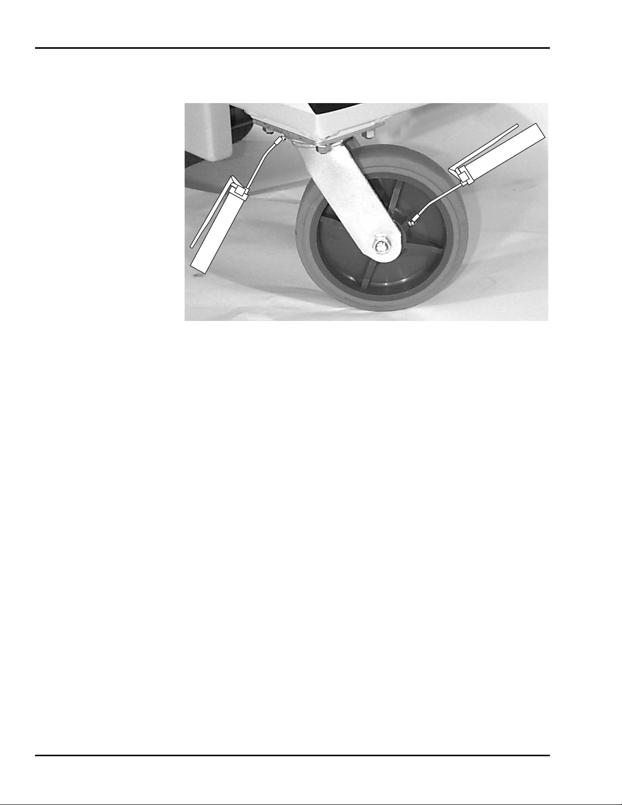
2. Grease all caster axles and swivel raceways at the 2 grease fittings on each
caster semiannually with wheel bearing grease. Refer to Figure 4-2.
Figure 4-2. Caster Lubrication
NOTE: The plastic slide blocks in the mast are made of a bearing material which
has a high degree of lubricity and need only be kept clean. However,
precautions should be taken to ensure that the paths along which the
blocks move are kept clean and lightly lubricated with a dry type silicon
lubricant.

4 — MAINTENANCE
4-5
4-3 HYDRAULIC SYSTEM
Hydraulic system maintenance varies by the amount of use and the environment in which
the lift is used. Constant attention to keep the oil clean and the reservoir properly filled
will help prevent possible damage to the system.
Hydraulic System Inspection
Check all hydraulic hoses and fittings for leaks and damage daily. Tighten or replace as
necessary to prevent hydraulic oil loss. Refer to the hydraulic schematic diagram in Sec-
tion 6 for general reference.
Fluid Check and Replacement
The reservoir should be filled to within 1/2 inch of the top with the platform in its lowest
position. The lift is shipped from the factory with Energol HLP-HD46 (BP Oil), a high
grade, non-foaming hydraulic oil designed for temperatures as low as -20°F/-29°C. Use
Dextron Automatic Transmission Fluid Type A for temperatures as low as -40°F/-40°C.
If either oil is not available, a good grade SAE 10W hydraulic oil may be used where the
minimum climatic temperature is above 32°F/0°C. SAE 5W hydraulic oil may be used
where temperatures are as low as 0°F/-18°C. Do not mix different hydraulic oils. Clean
the reservoir sump strainer and replace the hydraulic oil at least once a year or whenever
it becomes contaminated.
Hydraulic System Air Bleeding Procedure
Delayed response or sporadic action in the unit may indicate a presence of air in the cyl-
inder. Perform the following procedure to bleed air from the system.
1. Fill the reservoir with the proper hydraulic fluid.
2. Fully extend the lift.
3. Lower the unit to allow the oil with entrapped air to return to the reservoir, be-
ing careful not to overflow it.
4. Let the unit set while the air escapes the fluid and then repeat if necessary. Each
time the platform is lowered, refill the reservoir to prevent pumping more air
into the cylinder.
XLT-1571AC
4-6
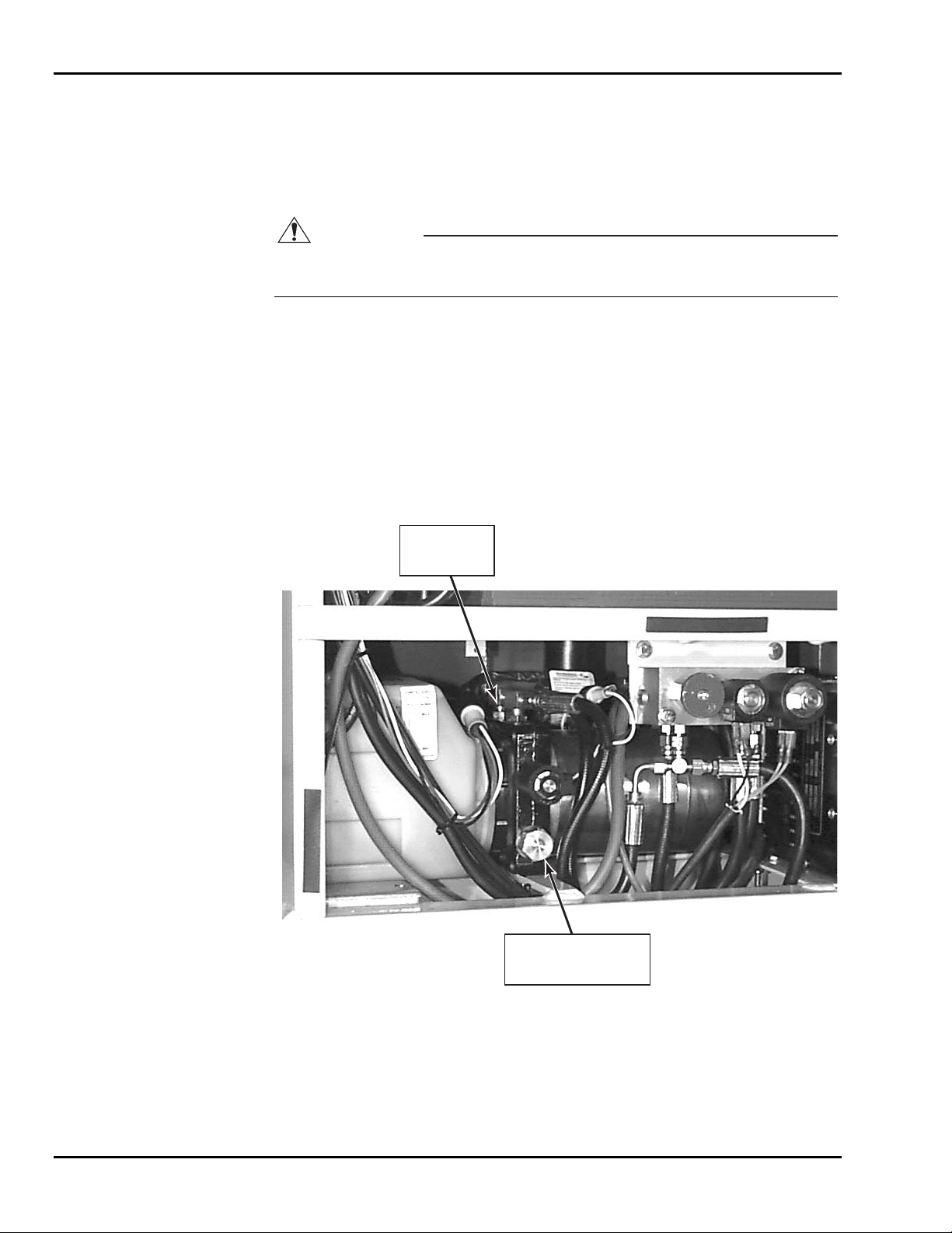
Pressure Relief Valve Reset
Perform the following procedure to reset the pressure relief valve. Refer to Figure 4-3.
1. Disconnect the hydraulic hose from the main pressure port.
2. Install a 4000 psi gauge into the main pressure port in the pump unit.
CAUTION
Do not adjust the pressure relief valve higher than 2100 psi. Overloading may
occur at pressures greater than 2100 psi.
3. Remove the hex cover from the pressure relief valve.
4. While depressing the
WHEEL DOWN/BASE ROLLS pushbutton on the lower control
box, adjust the screw until maximum pressure of 2100 psi is obtained.
5. After adjusting the pressure relief valve, replace the hex cover, remove the 4000
psi gauge, and reconnect the hydraulic hose to the main pressure port.
6. If a gauge is unavailable, place 500 pounds on the platform and adjust the pres-
sure relief valve screw so that the load can just be lifted without bypassing oil
through the pressure relief valve.
HEX COVER FOR
PRESSURE
RELIEF VALVE
MAIN
PRESSURE
PORT
Figure 4-3. Pressure Relief Valve Adjustment
Loading...