

Page 1
®
Model ET 5000W
Operation and Service Manual
2
2
6
1
/
5/16”BALL
5
L
L
A
B
”
Patented
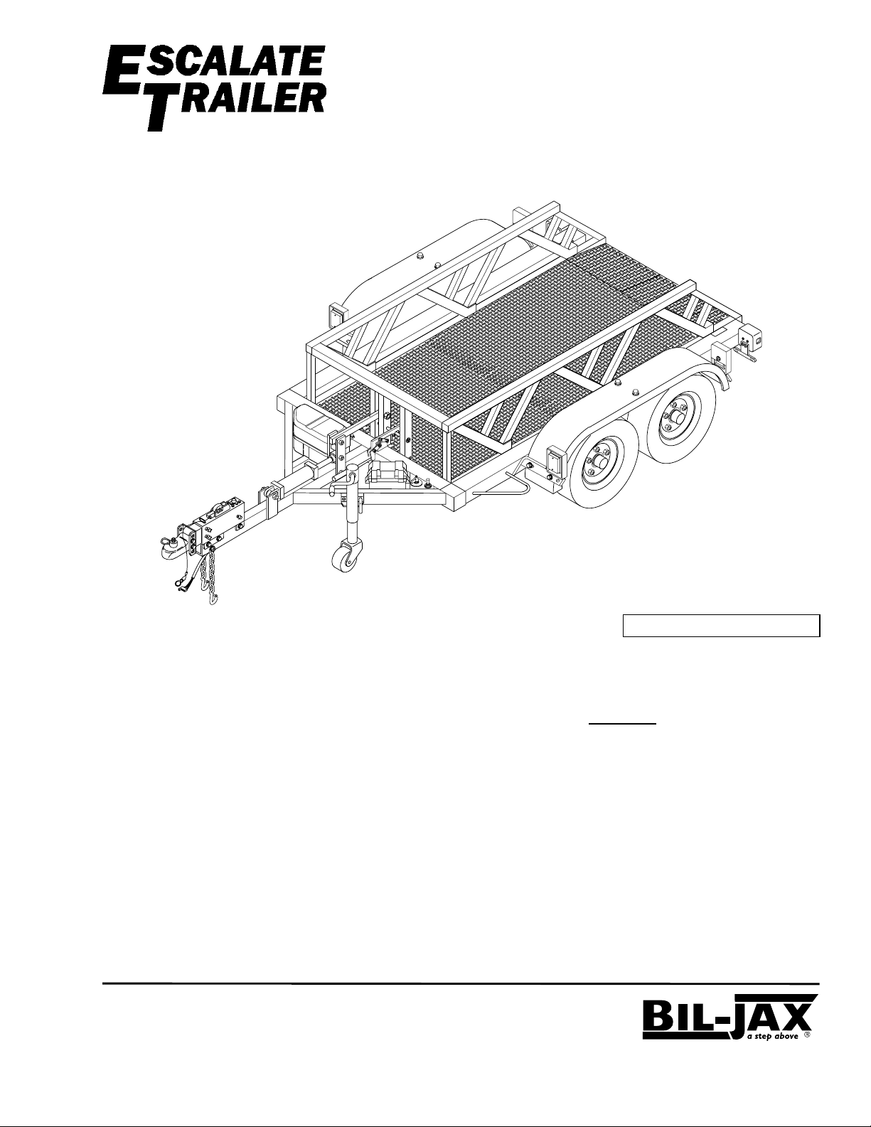
The ET 5000W E
level roll-on loading and roll-off unloading of
equipment with non-tilting
hydraulic lift deck allows one person to load and
unload equipment.
Contents
SAFETY ............................................................... 2
SPECIAL FEATURES .......................................... 2
SPECIFICATIONS................................................. 3
WARRANTY.......................................................... 3
TRAILER HITCHING ........................................... 5
EQUIPMENT LOADING ...................................... 6
SERVICE .............................................................. 8
PARTS LIST ........................................................ 12
SCALATE
Load Capacity: 5000 lbs
®
RAILER
T
offers ground
lowering deck. The
B33-01-0077
Page 2
SAFETY
Warnings and Cautions
Observe all warning labels on
the trailer. The trailer war ning
labels are shown here as a
reminder. Other warnings and
cautions are included in this
manual.
Failure to observe all warnings
may result in serious injury or
death. Failure to observe all
cautions may result in equipment
damage.
SPECIAL FEATURES
®
The Bil-Jax E
SCALATE
T
RAILER
WARNING
Stand clear of trailer while deck is being raised or
lowered. Moving deck will create p in c h p o in ts
causing serious crushing injury.
WARNING
Stand clear of trailer while deck
is being lowered. Contact with
trailer deck will cause serious
crushing injury.
WARNING
Trailer deck must be fully raised
with transport clamp locked
before towing trailer.
Failure to c o mply with these ins tructio n s
may result in serious personal injury or
death as well as damage to cargo.
includes all the features of a heavy duty trailer, plus:
Escalator Deck and Hydraulic Lift Heavy Duty Tie-Down Brackets
Surge Brake and Adjustable Hitch Stow-away Trailer Jack
LL
A
B
”
6
1
/
5
2
L
L
A
B
”
6
1
/
5
2
2
Page 3

SPECIFICATIONS
SCALATE
E
Model Number ET 5000W Serial Number ________________
Manufactured by: Bil-Jax, Inc.
Rated Capacity 5000 lbs. (2268 kg) max.
Weight (Empty) 2540 lbs. (1152 kg)
Overall Width 101 in. (256.5 cm)
Overall Length 204 in. (518.2 cm)
Overall Height (Bed Raised) 38-1/2 in. (97.8 cm)
Bed Height (Raised) 17-1/2 in. (44.5 cm)
Bed Size (Flat Surface) 61 in. wide x 96 in. long
Overall Bed Size
(Including Ramp)
Ramp Grade 6 degrees
Hitch Size 2-5/16 in. (5.87 cm) ball
Suspension Tandem Axle Leaf Spring
Brakes Standard – Hydraulic Surge; Optional – Electric
®
T
RAILER
125 Taylor Parkway
Archbold, Ohio 43502
419.445.9675
Specifications
(154.9 cm wide x 243.8 cm long)
61 in. wide x 120 in. long
(154.9 cm wide x 304.8 cm long)
WARRANTY
Bil-Jax warrants its trailers for one year from the date of delivery against all defect s of material and
workmanship, provided the unit is operated and maintained in com pliance with Bil-Jax’s operating and
maintenance instructions; structur al components are also warranted for one year. Bil-Jax will, at its
option, repair or replace any unit or component par t which f ails to function properly in normal use.
This warranty does not apply if the trailer and/or it s com ponent parts have been altered, changed, or
repaired without the consent of Bil-Jax or by anyone other than Bil-Jax or its factory trained personnel,
nor if the trailer and/or it s com ponents have been subjected to misuse, negligence, accident or any
conditions deemed other than those considered as occurring dur ing normal use.
Components not manufactured by Bil-Jax are covered by their respect ive manufacturers warranties. A
list of those components and their warrant ies is available upon written r equest to Bil-Jax.
Bil-Jax shall not in any event be liable for the cost of any special, indirect or consequential damages to
anyone, product, or thing. T his warrant y is in lieu of all other warranties expressed or implied. W e
neither assume nor authorize any representative, or other per son, to assume for us any other liability in
connection with the sale, rental, or use of this pr oduct .
3
Page 4

This page intentionally left blank
4
Page 5
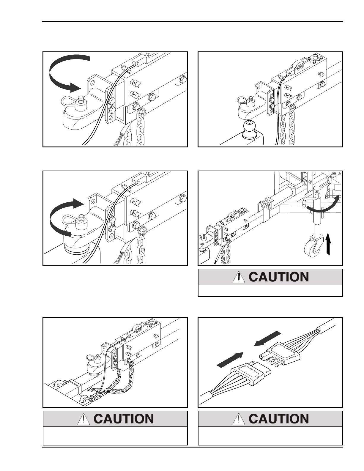
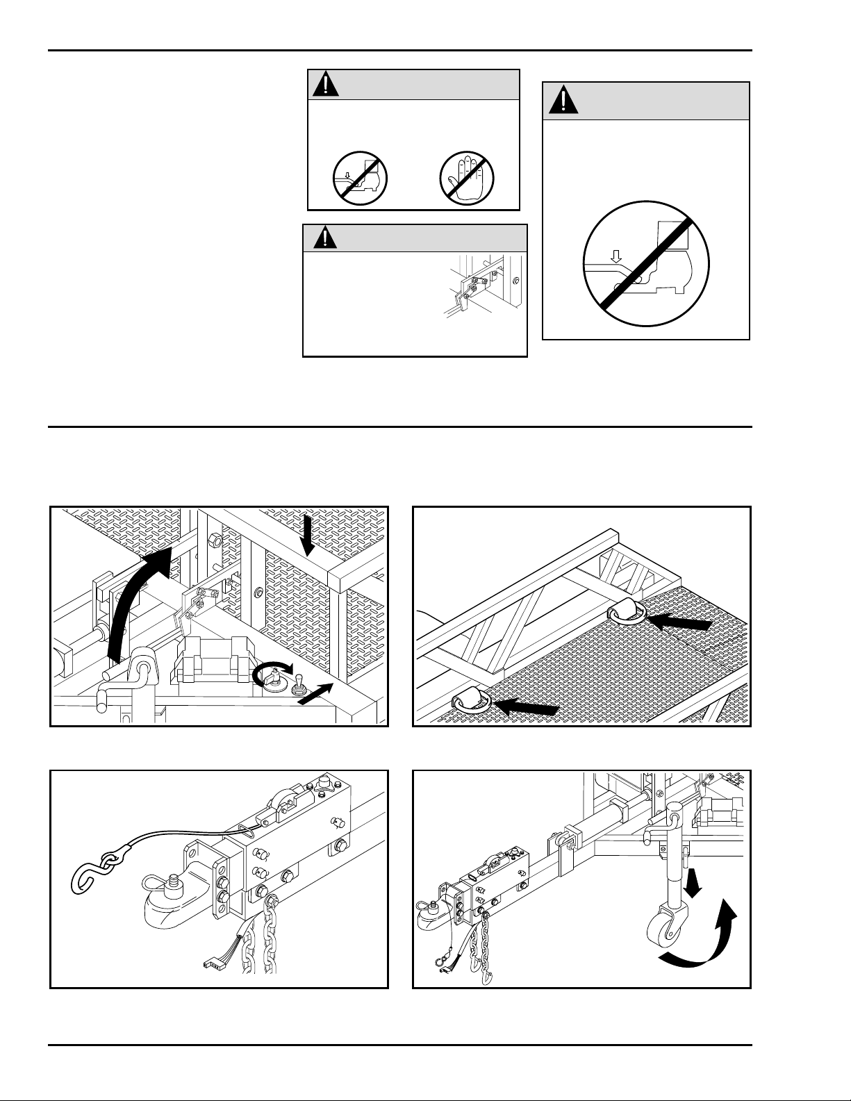
Hook Up the Trailer
TRAILER HITCHING
1. Raise trailer and loosen ball latch.
2. Line up ball with hitch.
ALL
” B
25/16
3. Lower hitch onto ball and tighten ball latch.
NOTE: The trailer hitch uses a 2 5/16 inch ball.
4. Raise and secure jack.
25/16
” B
ALL
ALL
” B
25/16
L
L
A
B
”
6
1
/
5
2
NOTE: Trailer fram e should be level when hitch
is on ball. See page 11 to adjust hitch heig ht .
5. Hook safety chains and attach breakaway
cable.
L
L
A
B
”
6
1
/
5
2
Always cross safety chains below tongue.
Safety chains must hold tongue up if hitch fails.
Always raise and pin the jack before towing.
6. Connect and check trailer light s.
Always check the tail lights and brake lights
before towing.
5
Page 6
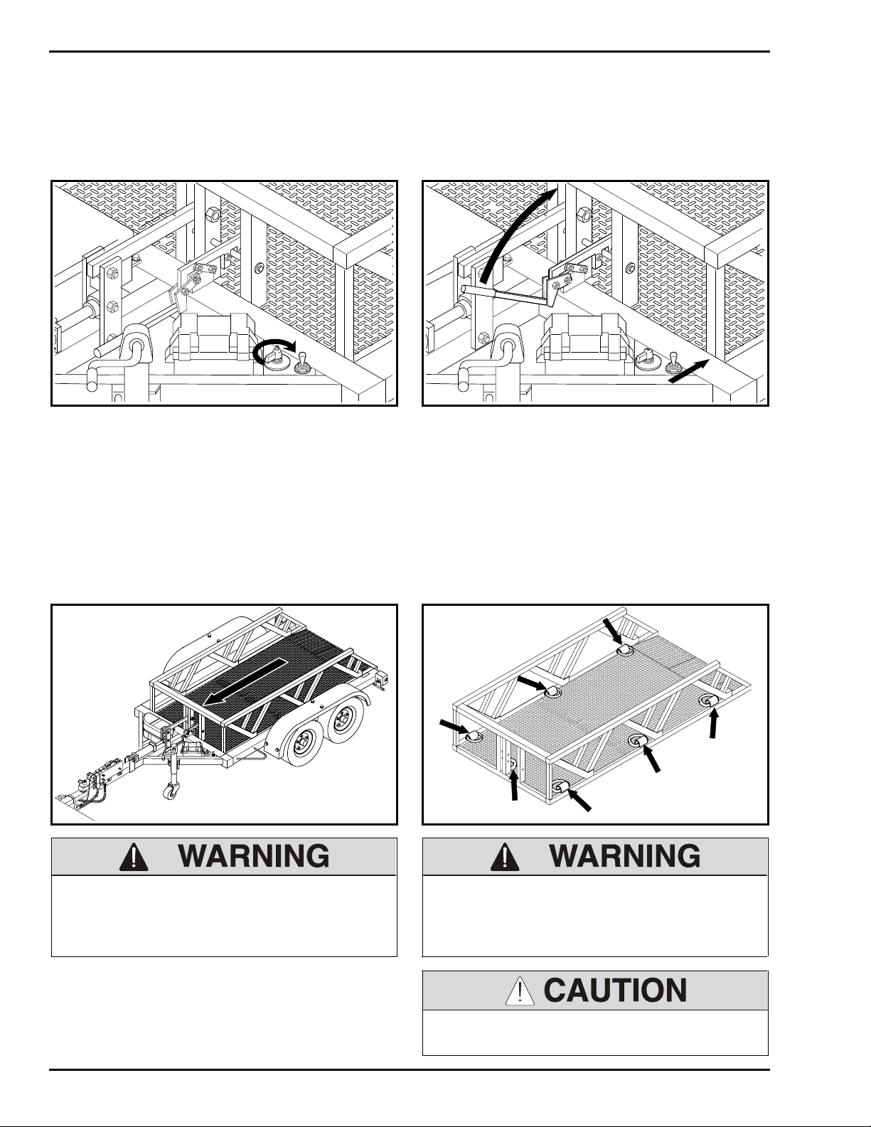
EQUIPMENT LOADING
Lower the Deck
NOTE: Trailer must be hitched t o vehicle according to page 5 before lowering or raising the deck.
1. Turn power switch to ON position.
2. Hold toggle switch in DOWN position. Lift
NOTE: The trailer frame should be on a level
surface when lowering the deck.
Load the Equipment
latch handle and push handle back.
1. Load equipment so that the result ing tongue
weight is 15 to 20% of the total load.
2. Install tie-down straps to keep the load from
shifting. Use 7 tie-down anchors shown.
BALL
25/16”BALL
5/16”
2
Maximum capacity = 5000 lbs. Do not exceed. Always secure the load with tie-down straps
before towing. Failure to properly secure t he
load may result in injury, death, or equipm ent
damage.
6
Do not hook tie-down straps on the roller
guides.
Page 7

Raise the Deck (trailer must be hitched to vehicle)
EQUIPMENT LOADING
1. Turn power switch to ON position and hold
toggle switch in up position. Stop raising deck
when deck latch is on latch bar.
Make sure people are away from the trailer
before raising the deck. Keep hands and feet
away from deck and rails. Hands and feet can
get crushed between the deck and fram e.
2. Verify that deck latch is on lat ch bar . Turn
power switch to OFF position.
If not clamped, the deck may fall during travel.
Always clamp the deck before towing. Failure to
clamp the deck may result in injury, death, or
equipment damage.
7
Page 8

SERVICE
Tire Maintenance Wheel Torque Requirements
At least once each week, use an accurate tire
pressure gage to check t he air pr essur e in all
four trailer tires. I nflate to the pressure
recommended by the tire manufacturer ( locat ed
on the tire).
Low or uneven tire pressures will not properly
support a loaded trailer and could lead to
premature tire wear.
When replacing tires, it is important to use a tire
of appropriate size and load rating (75D- 15) .
Failure to maintain proper torque on the lug
nuts may result in the wheel shearing off of the
trailer, possibly causing an accident and
seriously damaging the equipment.
It is extremely important to apply and maintain
proper wheel mounting torque on your axle.
Wheel nuts should be retorqued after 50 miles
and 100 miles and periodically there after.
The tightening of t he lug nuts should be torqued
in the sequence above.
Lug nuts should be torqued in stages:
Stage 1 Stage 2 Stage 3
25 Ft-Lbs 60 Ft-Lbs 100 Ft-Lbs
This procedure should be followed after each
time the tire is removed.
Lubrication (every 6 months)
Lubricate the following parts with clean motor oil or wheel bearing grease
where shown.
For additional brake operating and service instr uct ions, refer to the Surge Brake Act uator Manual
provided with the trailer.
NOTE: Be sure that no grease is applied to br ake pad.
Wheel Bearings
Hitch
Jack
Deck Latch
8
25/16”
Page 9

SERVICE
Hydraulic Fluid Levels
1. Remove cover from hydraulic pump. Check
fluid level in hydraulic reservoir.
2. Lower trailer deck. If oil level is below 3 inches
with deck down, add 1/2 quart of hydraulic oil.
Use BP type HLP-46 or 10w hydraulic oil.
NOTE: When trailer deck is raised, hydraulic
fluid level should be at least 1/2 of reservoir
volume.
3. Remove fill cap from surge brake reservoir.
Add DOT 3 brake fluid as needed to bring
fluid level to 1/2-inch below fill port.
ALL
” B
25/16
FILL CAP
Battery
1. Use hydrometer to check batter y charg e daily
or weekly, depending on frequency of use. If
the battery charge drops below 25% of f ull
charge (S.G. below 1.155 as corrected to
80°F) the battery must be recharged. Refer to
step 2 before charging battery.
3. Charge battery at one of the following charge
rates. The slow charge rate is preferred.
22 hours @ 5 amps
25 hours @ 20 amps
22 hours @ 50 amps
2. Check the electrolyte level weekly. If battery
charge is low, add water to bring electrolyte
level just above plates.
If battery is fully charg ed, add water to raise
electrolyte to full mark in each cell.
9
Page 10

SERVICE
Replacing the Lift Rollers
1. On a paved, level surface, pull trailer ont o 4x6
blocks. Jack up and unhitch the tr ailer .
3-1/2
2. Lower the deck until the front or rear lift rollers
can be removed from the roller access holes.
3. Loosen the setscrews that prevent the rollers
from backing out. The setscrews are located
on the trailer frame where the r oller s t hr ead
in. Use a socket wrench, with a 1 1/2” socket,
to unscrew and remove the rollers. Install and
tighten new rollers. Retighten the setscrews.
The deck must be supported by the paved
surface or shoring before the lift rollers are
removed.
NOTE: It is easier to remove and replace one
roller at a time. You can adjust the jack to access
each roller.
10
Page 11

SERVICE
Adjusting the Hitch Height
The trailer fram e and deck should be level for equipment loading and unloading. If the trailer hitch is
too high or too low when hitched to the towing vehicle, readjust the hit ch height.
1. Unhitch trailer. Remove hitch m ounting bolts
and nuts.
2. Install hitch in new position.
2
Adjust hitch height when trailer is empt y. Use
jack to aid in hitch adjustment .
5
Failure to install and tighten all hitch mounting
screws may cause serious equipment damage.
5
2
11
Page 12

PARTS LIST
Model ET 5000W E
Item No. Part No. Description Qty
1 B00-00-0114 Strap, Tie-Down, Battery Cover 1
2 B01-10-0150 Box, Battery (includes lid & strap) 1
3 0090-0188 Nut, Nylon Lock, 3/8-16 1
4 B01-01-0027 Cable, Battery, 19” 2
5 0090-0160 Nut, Hex, 5/16-18 1
6 B01-04-0002 Battery, 12 Volt, Deep Cycle 1
7 B01-02-0060 Switch, Master Power 1
8 B01-02-0019 Switch, Toggle 1
9 B06-00-0345 Decal, UP/DOWN 1
10 B01-10-0151 Light, Marker 2
11 B01-10-0152 Grommet, Marker Light 2
12 B01-10-0153 Plug Assembly, Marker Light 2
13 0090-0162 Nut, Hex, 3/8-16 1
14 B01-09-0026 Bushing, Hole 2
15 B01-09-0057 Bushing, Tube 4
16 B01-09-0018 Boot, Terminal 2
17 B01-01-0119 Cable, Battery, 55” 1
*18 B23-02-0046 Jack, Tongue 1
19 0090-0192 Hex Nut, Self-Locking, ½-13 1
20 B25-00-0062 Bushing, Flanged Sleeve 1
21 0090-0081 Screw, Cap, ½ -13 x 5 1
22 0090-0574 Washer, SAE Flat, ½ 2
23 B03-00-0017 Safety Chain Assembly 2
24 0090-0344 Screw, #10-24 x ½ 3
25 B01-01-0120 Harness, Wiring 1
26 0090-0192 Nut, Lock, ½-13 1
27 0090-0878 Screw, Cap, 5/8-11 x 4 ¾ 5
28 0090-0425 Washer, SAE Flat, 5/8 10
29 B12-00-0068 Coupler, Adjustable, 2 5/16 1
30 0090-0194 Nut, Lock, 5/8-11 5
31 B12-00-0080 Hitch, Brake Surge Type 1
32 B21-00-0016 Kit, Brake Line 1
33 B04-07-0036 Clamp, Hose 1
34 0090-0183 Nut, Lock, ¼-20 1
35 B00-00-0112 Face Plate, Power Switch 1
36 B01-09-0081 Wire, Butt Splice 2
37 B06-00-0357 Transfer, 2 5/16 Ball Hitch 1
SCALATE
®
T
RAILER
, Hitch Section
* Jack assembly includes items 18, 19, and 20.
12
Page 13

PARTS LIST
2
1
28
30
29
26
22
28
28
31
27
5
13
4
4
6
3
2
8
7
9
32
33
34
35
28
27
36
12
7
LL
A
B
”
5/16
2
37
22
21
4
15
14
11
24
10
8
17
25
24
20
19
23
18
16
Model ET 5000W E
SCALATE
®
T
RAILER
, Hitch Section
13
Page 14

PARTS LIST
Model ET 5000W E
Item No. Part No. Description Qty
1 0090-0428 Washer, SAE Flat, ¾ 2
2 B07-06-1035 Bar, Deck Latch 1
3 0090-0147 Pin, Cotter, 1/8 x 1-¼ 2
4 0090-0689 Nut, Nylon Lock, 1-8 5
5 0090-0429 Washer, SAE Flat, 1 2
6 0090-0902 Screw, Cap, 1-8 x 7 1
7 B07-07-5010 Bar, Lift 1
8 B07-10-1087 Spacer, 1-7/32 in. 2
9 B12-00-0076 Link, Lift Multiplier 1
10 0090-0901 Screw, Cap, 1-8 x 6-½ 3
11 0090-0188 Nut, Nylon Lock, 3/8-16 6
12 B39-00-0031 Spring, Extension 2
13 0090-0422 Washer, SAE Flat, 3/8 2
14 B07-06-5353 Link, Latch 2
15 B07-06-5358 Deck Latch 1
16 0090-0049 Screw, Cap, 3/8-16 x 2-¼ 2
17 0090-0046 Screw, Cap, 3/8-16 x 1-¾ 4
18 B11-00-0040 Lever, Latch 1
19 0090-0040 Screw, Cap, 3/8-16 x ¾ 2
20 0090-0210 Washer, Split Lock, 3/8 2
21 B18-00-0130 Cover, Pump (includes top, bottom, & strap) 1
22 0090-0900 Screw, Cap, 1-8 x 5-½ 1
23 B02-03-0016 Hydraulic Cylinder 1
23A B02-13-0104 Seal Repair Kit, Hydraulic Cylinder 1
24 B02-02-0072 Fitting, Hydraulic 1
25 B02-01-0135 Hose, Hydraulic, ¼” dia. x 40” 1
26 B02-01-0026 Hose, Hydraulic, 3/8” dia. x 30” 1
27 B02-02-0070 Fitting, Hydraulic 1
28 B07-10-1086 Spacer 2
29 B01-09-0033 Wire End, Fork 3
30 B02-02-0017 Fitting, Hydraulic 1
31 B02-04-0002 Valve, Flow Control 1
32 B02-02-0185 Fitting, Hydraulic 1
33 B02-02-0072 Fitting, Hydraulic 1
34 B02-05-0023 Pump Assembly, Hydraulic 1
35 B00-00-0115 Strap, Tie-Down, Pump Cover 1
36 B46-00-0026 Grip, Handle 1
SCALATE
®
T
RAILER
, Lift Section
14
Page 15

26
30
25
35
4
24
31
32
29
22
21
33
34
28
27
23, 23A
PARTS LIST
4
1
2
5
8
4
28
3
5
7
8
9
11
10
36
11
18
13
12
11
6
1
15
14
14
16
13
12
21
20
19
Model ET 5000W E
SCALATE
®
T
RAILER
17
, Lift Section
15
Page 16

PARTS LIST
Model ET 5000W E
Item No. Part No. Description Qty
1 B12-00-0094 Deck Weldment 1
2 0090-0060 Screw, Cap, 3/8-16
x 5-1/2
3 0090-0422 Washer, SAE Flat, 3/8 8
4 B30-00-0026 Spacer, Guide Bar 4
5 B11-00-0038 Guide Bar 2
6 0090-0188 Nut, Nylon Lock, 3/8-16 4
7 0090-0355 Setscrew, Cup Pt.
1/4-20 x 1/4
8 B12-00-0095 Frame Weldment 1
9 B25-00-0058 Roller, Lift 6
10 0090-0509 Screw, Cap, Nylon,
3/8-16 x 3/8
11 B06-00-0313 Decal, “Stand clear ...” 2
12 B31-00-0029 Wear Pad, Guide Bar 2
13 B01-10-0024 Light Assembly, Left Tail 1
13A B01-10-0023 Light Assembly, Right
Tail
13B B01-10-0070 Lamp, Tail Light,
GE-1157
13C B01-10-0069 Replacement Lens, Tail
Light
14 0090-0206 Washer, Split Lock, ¼ 4
15 0090-0159 Nut, Hex, 1/4-20 4
16 0090-0005 Screw, Cap, 1/4-20
x 3/4
17 B29-00-0037 Bracket, License Plate 1
18 0090-0419 Washer, SAE Flat, ¼ 2
19 0090-0183 Nut, Nylon Lock, 1/4-20 2
20 0090-0896 Nut, Lock, 3/8-16 20
21 0090-0042 Screw, Cap, 3/8-16 x 1 20
22 B10-00-0033 Brake Assembly,
Left-Hand
22A B10-00-0032 Brake Assembly,
Right-Hand
22B B10-00-0038 Brake Pad, Front 4
22C B10-00-0016 Brake Pad, Rear 4
*23 B12-00-0071 Wheel Assembly, 6 Lug 4
24 B25-00-0060 Bearing, Wheel, Inner 4
24A B25-00-0061 Bearing, Wheel, Outer 4
25 B32-00-0014 Seal, Bearing 4
26 B32-00-0013 Cap, Hub 4
27 0090-0624 Nut, Wheel Lug 24
* Wheel assembly includes items 24 through 27.
SCALATE
®
T
2
6
8
1
2
2
2
2
2
RAILER
, Deck and Frame Section
Item No. Part No. Description Qty
28 0090-0882 Washer, Wheel 4
29 0090-0880 Nut, Castle 4
30 0090-0881 Pin, Cotter, 5/32 x 2 4
31 B08-02-0003 Tire, 75D-15 4
32 B39-00-0035 Hanger Kit, Tandem
Spring
33 B39-00-0033 U-Bolt Kit, Leaf Spring 2
34 B31-00-0028 Pad, Leaf Spring 4
35 B39-00-0036 Leaf Spring, Double Eye 4
36 B06-00-0317 Decal, Escalate Trailer
Logo
37 B06-00-0381 Decal, ET 5000W 2
38 B06-00-0312 Decal, “Moving Deck ...” 2
39 B06-00-0344 Decal, Raise Bar, Press
Switch
40 Not
Replaceable
41 0090-0032 Screw, Cap, 5/16-18 x
42 0090-0208 Washer, Split Lock, 5/16 12
43 0090-0420 Washer, SAE Flat, 5/16 12
44 B18-00-0134 Fender 2
45 0090-0183 Nut, Nylon Lock, 1/4-20 12
46 B04-07-0032 Clamp, Hose 9
47 B06-00-0354 Decal, #5000 Maximum 1
48 0090-0917 Screw, Cap, 3/8-16
49 0090-0033 Screw, Cap, 5/16-18 x
50 B29-00-0147 Bracket, Side Marker
51 B01-10-0021 Light, Side Marker,
51A B01-10-0066 Replacement Lens –
51B B01-10-0068 Lamp, Side Marker 2
52 B29-00-0146 Bracket, Side Marker
53 B01-10-0022 Light, Side Marker,
53A B01-10-0067 Replacement Lens –
53B B01-10-0068 Lamp, Side Marker 2
Plate, Serial # 1
1-1/2
x 6
1-3/4
Light, Left Front/Right
Rear
Left/Right Front - Amber
Amber
Light, Left Rear/Right
Front
Left/Right Rear - Red
Red
1
2
1
4
2
8
2
2
2
2
2
2
16
Page 17

PARTS LIST
47
44
43
1
7
8
9
42
52
41
2
4
3
6
53,53A,53B
11
10
3
48
3
4
5
3
6
13,13A,
12
13B,13C
42
49
46
45
39
40
Model ET 5000W E
43
51,
51A,
51B
38
SCALATE
50
®
T
37
RAILER
20
32
32
22,22A,22B,22C
32
25
33
34
35
, Deck and Frame Section
36
33
23
15
24
32
21
30
14
24A
19
29
18
28
31
16
17
26
27
17
Page 18

PARTS LIST
Model DB-1343 Hydraulic Pump Assembly
Item No. Part No. Description Qty
1 B02-15-0119 Coupling, SAE 9T-20/40 1.26 1
2 B02-15-0128 Ball, 0.375 Steel, G50 1
3 B02-15-0091 Seal, Shaft 0.500 x 1.00 x 0.25 1
4 B02-15-0201 Breather, Plastic 1
5 B02-15-0093 Washer, 0.338 x 0.625 x 0.60 Steel 3
6 B02-15-0166 Washer, Lock, 0.255 x 0.485 x 0.062 1
8 B02-15-0061 Magnet, Plumbing 1
9 B02-15-0121 Filter, 149 Micron 1.50 x 1 1
10 B02-15-0122 Motor, DC - 12V, 1T, Std. Duty 1
11 B02-15-0123 Screw, Taptite, 1/4-20 x 0.25, Hex 1
12 B02-15-0358 Screw, Taptite, 1/4-20 x 0.37, Hex 1
13 B02-15-0125 Cover, Suction, 3/8 NPT 1
14 B02-15-0126 Screw, Taptite, M6 x 1, 12 mm 2
15 B02-15-0345 Solenoid, Smart Start, 12VDC 1
17 B02-15-0197 Cartridge, Check Valve 1
18 B02-15-0170 Screw, 5/16-18 x 1.00 Torx 1
19 B02-15-0359 Bolt, M8 x 75 mm, Hex 2
20 B02-15-0360 Spring, RV 1000-2000 PSI Green 1
21 B02-15-0349 Coil, Solenoid, 12VDC, 2 Pin 1
22 B02-15-0199 Bolt, #12-24 x 0.50 Hex Washer 4
23 B02-15-0114 Pin, 1/8 x ¼ 1
24 B02-15-0073 O-Ring, 2-348 Buna 1
26 B02-15-0355 Wiring Assembly, 4-Pin 1
27 B02-15-0356 Endhead, Finished 1
28 B02-15-0078 Pump Assembly, 1.6 Short Spline 1
29 B02-15-0206 Tank, Plastic, Horizontal Mount w/Drain 1
30 B02-15-0030 Cap, Relief, Assembly (B-2) 1
31 B02-15-0195 Plug, Plumbing, 9/16 SAE 1
32 B02-15-0204 Plug, Plumbing, 1/16 NPT Flush 2
33 B02-02-0059 Nylon Ell (X-111) 1
34 B02-15-0026 Screw, Valve, Adjustment 1
35 B02-15-0357 Valve Cartridge, Relief, Normally Closed, w/o Coil 1
36 B02-15-0102 Nameplate, Fenner Serial 1
18
Page 19

PARTS LIST
Model DB-1343 Hydraulic Pump Assembly
19
Page 20

125 Taylor Parkway Archbold, OH 43502
Phone 419-445-9675 Fax 419-445-0367
 Loading...