

Page 1
®
AERIAL WORK PLATFORMS
SkyRider 15
Electric Hydraulic Lift Platform
Operation and
Maintenance Manual
WARNING
DANGER
W
O
R
K
F
O
R
C
E
WARNING
B33-01-0078
Page 2

TELESCOPIC PERSONNEL LIFT
This equipment is designed and manufactured in compliance with the duties, responsibilities, and standards set forth for manufacturers in the ANSI 92.6 standard
in effect at the time of manufacture.
This equipment will meet or exceed applicable OSHA codes and ANSI A92.6 standards when used in accordance with sections 5, 6, 7, 8, 9, 10, and 11 of ANSI A92.6
and all other manufacturer’s recommendations.
It is the responsibility of the user of this equipment to follow all applicable ANSI,
OSHA, Federal, State, and local codes and regulations that govern the safe operation of this equipment.
Page 3

Table of Contents
1 Safety................................................................................................................1-1
1-1 Introduction.........................................................................................
1-2 Before Operation ...............................................................................
1-3 During Operation................................................................................
1-4 Maintenance Safety............................................................................
1-5 Damaged Equipment Policy .............................................................
2 Introduction.....................................................................................................
2-1 General Description...........................................................................
2-2 Specifications......................................................................................
2-3 Warranty.............................................................................................
3 Operation.........................................................................................................
3-1 Operator Controls ..............................................................................
3-2 Normal Operating Procedure............................................................
3-3 Emergency Lowering Procedures.....................................................
3-4 Lift Vehicle Transport ......................................................................
4 Maintenance ....................................................................................................
4-1 Scheduled Service Checks................................................................
4-2 Lubrication..........................................................................................
4-3 Hydraulic System...............................................................................
4-4 Electrical System .............................................................................
4-5 Lift Chains and Slide Blocks ........................................................
4-6 Troubleshooting................................................................................
5 Replacement Decals ........................................................................................
1-1
1-3
1-4
1-6
1-7
2-1
2-1
2-2
2-2
3-1
3-1
3-3
3-5
3-6
4-1
4-1
4-3
4-5
4-11
4-12
4-15
5-1
6 Parts List..........................................................................................................
6-1 Top Mast Parts List..........................................................................
6-2 Center Mast Parts List......................................................................
6-3 Lower Mast Parts List......................................................................
6-4 Battery Compartment Parts List.......................................................
6-5 Hydraulic Pump Compartment Parts List.....................................
6-6 Base Parts List ................................................................................
6-7 Base Mast Parts List ......................................................................
6-8 Drive Axle and Steering Parts List ..............................................
6-9 Pothole Guard Parts List................................................................
6-10 Platform Parts List..........................................................................
6-11 Upper Control Box Parts List .......................................................
6-12 Hydraulic Unit Parts List...............................................................
6-13 Hydraulic Cylinder, Fittings, and Hoses Parts List......................
7 ANSI Reprint..................................................................................................
6-1
6-2
6-4
6-6
6-8
6-10
6-12
6-14
6-16
6-18
6-20
6-22
6-24
6-26
7-1
i
Page 4

List of Illustrations
Figure 3-1. Lower Control Box................................................................................. 3-1
Figure 3-2. Upper Control Box.................................................................................
Figure 3-3. Battery On/Off Switch............................................................................
Figure 3-4. Emergency Lowering Valve...................................................................
Figure 3-5. Lifting Brackets and Tie Down Rings....................................................
Figure 3-6. Travel Brake and Steering Linkage........................................................
Figure 4-1. Lift Chains Lubrication..........................................................................
Figure 4-2. Mast Slide Ways Lubrication.................................................................
Figure 4-3. Rear Casters Lubrication........................................................................
Figure 4-4. Front Caster Pillow Blocks Lubrication.................................................
Figure 4-5. Pressure Relief Valve Adjustment..........................................................
Figure 4-6. Flow Restrictor Valve ............................................................................
Figure 4-7. Up Valve Operation Check ....................................................................
Figure 4-8. Hydraulic Cylinder Disassembly..........................................................
Figure 4-9. Battery Charger Receptacle..................................................................
Figure 4-10. Chain Elongation Inspection................................................................
Figure 4-11. Lift Chains Adjustment........................................................................
Figure 4-12. Slide Blocks Adjustment......................................................................
Figure 4-13. Main Controller Board .........................................................................
Figure 4-14. Hydraulic Diagram...............................................................................
Figure 4-15. PC Logic Diagram................................................................................
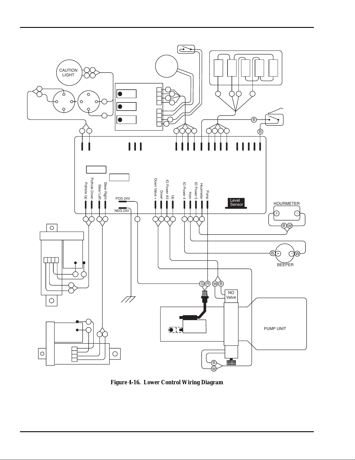
Figure 4-16. Lower Control Wiring Diagram...........................................................
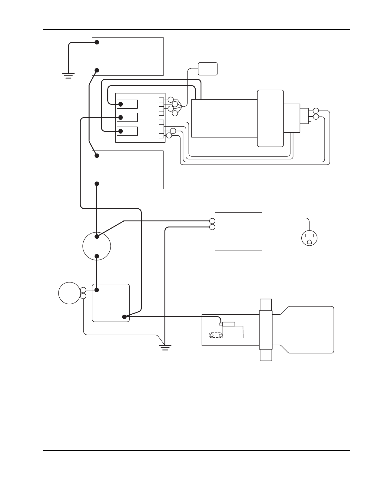
Figure 4-17. Drive Wiring Diagram..........................................................................
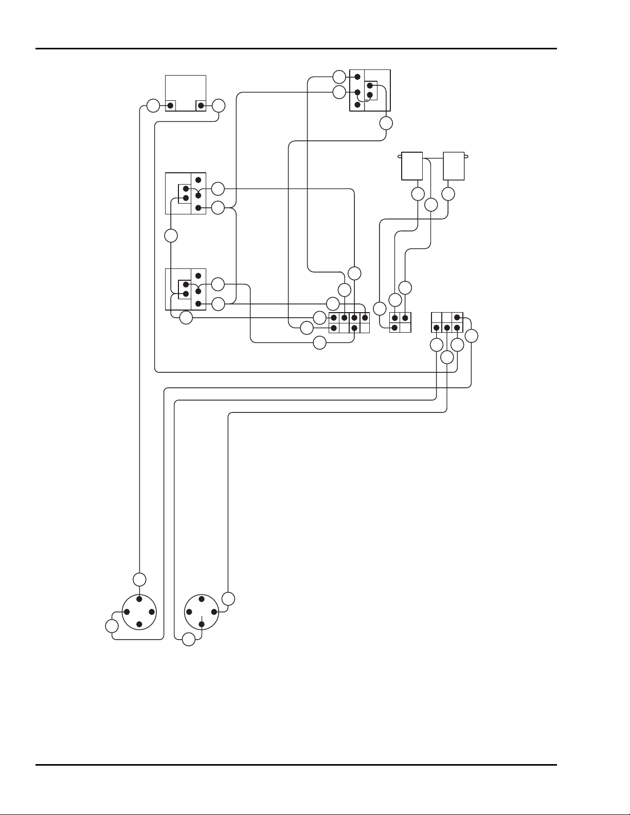
Figure 4-18. Upper Control Wiring Diagram ...........................................................
Figure 5-1. Replacement Decals ...............................................................................
Figure 5-2. Decal Locations, Side View...................................................................
Figure 5-3. Decal Locations, Rear View...................................................................
Figure 6-1. Top Mast ................................................................................................
Figure 6-2. Center Mast ............................................................................................
Figure 6-3. Lower Mast ............................................................................................
Figure 6-4. Battery Compartment .............................................................................
Figure 6-5. Hydraulic Pump Compartment.............................................................
Figure 6-6. Base......................................................................................................
Figure 6-7. Base Mast.............................................................................................
Figure 6-8. Drive Axle and Steering.......................................................................
Figure 6-9. Pothole Guard.......................................................................................
Figure 6-10. Platform................................................................................................
Figure 6-11. Upper Control Box...............................................................................
Figure 6-12. Hydraulic Unit Assembly.....................................................................
Figure 6-13. Hydraulic Cylinder, Fittings, and Hoses ..............................................
3-2
3-3
3-5
3-6
3-6
4-3
4-3
4-4
4-4
4-6
4-7
4-8
4-10
4-11
4-12
4-13
4-14
4-18
4-20
4-21
4-22
4-23
4-24
5-2
5-3
5-4
6-2
6-4
6-6
6-8
6-10
6-12
6-14
6-16
6-18
6-20
6-22
6-24
6-26
ii
Page 5

List of Tables
Table 1-1. Minimum Safe Approach Distances .......................................................1-4
Table 2-1. Specifications..........................................................................................
Table 4-1. Daily/Weekly Service Checks.................................................................
Table 4-2. Monthly Service Checks.........................................................................
Table 4-3. Troubleshooting Chart ..........................................................................
Table 4-4. Main Controller LED Indicators...........................................................
Table 5-1. Replacement Decals................................................................................
Table 6-1. Top Mast Parts List.................................................................................
Table 6-2. Center Mast Parts List.............................................................................
Table 6-3. Lower Mast Parts List.............................................................................
Table 6-4. Battery Compartment Parts List..............................................................
Table 6-5. Hydraulic Pump Compartment Parts List .............................................
Table 6-6. Base Parts List.......................................................................................
Table 6-7. Base Mast Parts List..............................................................................
Table 6-8. Drive Axle and Steering Parts List........................................................
Table 6-9. Pothole Guard Parts List.......................................................................
Table 6-10. Platform Parts List.................................................................................
Table 6-11. Upper Control Box Parts List................................................................
Table 6-12. Hydraulic Unit Parts List ......................................................................
Table 6-13. Hydraulic Cylinder, Fittings, and Hoses Parts List...............................
Table 7-1. Minimum Safe Approach Distance (M.S.A.D.) to energized
(exposed or insulated) power lines and parts........................................
2-2
4-1
4-2
4-15
4-19
5-1
6-3
6-5
6-7
6-9
6-11
6-13
6-15
6-17
6-19
6-21
6-23
6-25
6-27
7-15
iii
Page 6

iv
Page 7

1
Safety
1-1 INTRODUCTION
Familiarity and proper training are required for the safe operation of mechanical equipment. Equipment operated improperly or by untrained personnel can be dangerous. Read
the operating instructions in this manual and become familiar with the location and
proper use of all controls. Inexperienced operators should receive instruction from persons who are familiar with the equipment before operating the machine. The use of intelligence and common sense in the operation of mechanical equipment is the best practice
in any safety policy. Be professional and always observe the safety procedures set forth
in this manual.
All OSHA, ANSI, state and local codes and regulations pertaining to this equipment
should be obtained, read, and thoroughly understood before attempting to operate this
equipment. Persons under the influence of drugs, alcohol, or prescription medication
should not be on or near this equipment. Common sense should be implemented at all
times during the use of this equipment. Do not operate this equipment in areas where
equipment or user may come in contact with live power source.
The information contained herein is not to be considered as legal advice and is intended
for informational purposes only. This information is offered to alert Workforce customers to procedures that may be of concern to them.
This information is not intended to be all-inclusive and is to b e followed in the use of
Workforce equipment only.
For any questions concerning the safe use of this equipment, call 419.445.9675 before
operating.
1-1
Page 8
SkyRider 15
Safety Notes
This manual contains DANGERS, WARNINGS, CAUTIONS, and NOTES that must be
followed to prevent the possibility of improper service, damage to the equipment, or personal injury.
DANGER
Dangers warn of equipment operation near electrical power lines that could lead
to personal injury or death.
WARNING
Warnings describe conditions or practices that could lead to personal injury or
death.
CAUTION
Cautions provide information important to prevent errors that could damage machine or components.
NOTE: Notes contain additional information important to a procedure.
1-2
Page 9

1 — SAFETY
1-2 BEFORE OPERATION
Read and observe the following general safety precautions before operating the SkyRider 15.
• ALWAYS survey the usage area for potential hazards such as untampered earth
fills, unlevel surfaces, overhead obstructions, and electrically charged conductors or wires. Be aware of any potential hazards and always consider what could
happen. Watch for moving vehicles in the operating area.
• ALWAYS read, understand, and follow the procedures in this manual before attempting to operate equipment.
• ALWAYS inspect the equipment for damaged or worn parts. Check for cracked
welds, hydraulic leaks, damaged wiring, loose wire connectors, damaged casters, and damaged pothole guards. Also check for any improper operation.
NEVER operate equipment if damaged in any way. Improperly operating
equipment must be repaired before using.
• ALWAYS wear proper clothing for the job. Wear protective equipment as required by federal, state, or local regulations.
• ALWAYS locate, read, and follow all directions and warnings displayed on the
equipment.
• ALWAYS inspect the equipment for “DO NOT USE” tags installed by maintenance personnel. NEVER use tagged equipment until repairs are made and all
tags are removed by authorized maintenance personnel.
• ALWAYS make sure the platform is free of mud, grease, or other foreign material. This will reduce the possibility of slipping.
• NEVER allow improperly trained personnel to operate this equipment. Only
trained and authorized personnel shall be allowed to operate this equipment.
• NEVER operate this equipment if you are under the influence of alcohol or
drugs or if you feel ill, dizzy, or unsteady in any way. Operators must be physically fit, thoroughly trained, and not easily excitable.
• NEVER modify, alter, or change the equipment in any way that would affect its
original design or operation in any way.
• NEVER operate this equipment in ways for which it is not intended.
1-3
Page 10

SkyRider 15
1-3 DURING OPERATION
Read and observe the following general safety precautions at all times during operation
of the SkyRider 15.
DANGER
This machine is not insulated for use near electrical power lines and DOES NOT
provide protection from contact with or close proximity to any electrically
charged conductor. Operator must maintain safe clearances at all times (10 feet
minimum) and always allow for platform movement such as wind induced sway.
Always contact the power company before performing work near power lines. Assume every line is hot. Remember, power lines can be blown by the wind.
Refer to Table 1-1 for minimum safe approach distances between machine and electrical
power lines.
Table 1-1. Minimum Safe Approach Distances
Voltage Range
(Phase to Phase)
0 to 300V Avoid Contact
Over 300V to 50KV 10 3.05
Over 50KV to 200KV 15 4.60
Over 200KV to 350KV 20 6.10
Over 350KV to 500KV 25 7.62
Over 500KV to 750KV 35 10.67
Over 750KV to 1000KV 45 13.72
Minimum Safe Approach Distance
(Feet) (Meters)
• ALWAYS position lift far enough away from power sources to ensure that no
part of the lift can accidentally reach into an unsafe area.
• ALWAYS operate only on a firm and level surface. NEVER use on surfaces
that do not support the weight of the equipment and its rated load capacity.
• ALWAYS keep yourself and all personnel away from potential pinch or shear
points.
• ALWAYS report any misuse of equipment to the proper authorities. Horseplay
is prohibited.
• ALWAYS maintain good footing on the platform. NEVER wear slippery soled
shoes.
• ALWAYS make certain all personnel are clear and there are no obstructions before repositioning platform.
• ALWAYS cordon off area around the base to keep personnel and other equipment away from it while in use.
• ALWAYS stay clear of wires, cables, and other overhead obstructions.
• ALWAYS disconnect power at the batteries when not in use to guard against
unauthorized use.
1-4
Page 11

1 — SAFETY
• NEVER allow electrode contact with any part of the platform if welding is being performed from the platform.
• NEVER override or by-pass manufacturer's safety devices.
• NEVER release the travel brake or tow the lift vehicle while a person or materi-
als are on board.
• NEVER stand or sit on guard rails. Work only within the platform guard rail
area and do not lean out over guard rails to perform work.
• NEVER attempt to increase working height with boxes, ladders, or other means.
• NEVER operate this equipment when exposed to high winds, thunderstorms,
ice, or any other weather conditions that would compromise the safety of the
operator.
• NEVER climb up or down masts.
• NEVER allow ropes, electric cords, hoses, etc. to become entangled in the
equipment when the platform is being raised or lowered.
• NEVER exceed manufacturer's platform load limits and make sure all materials
are evenly distributed over the entire platform.
• NEVER exceed platform load ratings by transferring loads to platform at elevated heights.
• NEVER use guard rails to carry materials and never allow overhang of materials
when raising or lowering platform.
1-5
Page 12

SkyRider 15
1-4 MAINTENANCE SAFETY
Read and observe the following general safety precautions when performing maintenance
on the SkyRider 15.
• ALWAYS perform maintenance procedures according to manufacturer's requirements. NEVER short change maintenance procedures.
• ALWAYS check hydraulic system. Make sure all lines, connectors, and fittings
are tight and in good condition.
• ALWAYS keep all mechanisms properly adjusted and lubricated according to
maintenance schedule and manufacturers specifications.
• ALWAYS perform a function check of operating controls before each use and
after repairs have been made.
• ALWAYS locate and protect against possible pinch points prior to performing
maintenance and repairs.
• ALWAYS use only factory-approved parts to repair or maintain this equipment.
If this equipment is rebuilt, retesting is required in accordance with factory instructions.
• NEVER add unauthorized fluids to the hydraulic system or battery. Check
manufacturers specifications.
• NEVER exceed the manufacturer's recommended relief valve settings.
• NEVER attempt repairs you do not understand. Consult manufacturer if you
have any questions regarding proper maintenance, specifications, or repair.
Battery Maintenance
Read and observe the following general safety precautions when performing battery
maintenance on the SkyRider 15.
• ALWAYS check battery acid level daily. Check battery charge indicator for
proper state of charge on maintenance free batteries before using lift.
• ALWAYS wear safety glasses when working near battery.
• ALWAYS avoid contact with battery acid. Battery acid causes serious burns.
Avoid contact with skin or eyes. If accidental contact occurs, flush with water
and consult a physician immediately.
• ALWAYS disconnect ground cable first when removing battery.
• ALWAYS connect ground cable last when installing battery.
• ALWAYS charge batteries in open, well-ventilated areas.
• NEVER smoke when servicing battery.
• NEVER allow batteries to overcharge and boil.
• NEVER short across battery posts to check for current. NEVER break a live cir-
cuit at battery.
• NEVER jump start other vehicles using lift battery.
1-6
Page 13

1 — SAFETY
1-5 DAMAGED EQUIPMENT POLICY
Safety Statement
At Workforce, we are dedicated to the safety of all users of our products. Therefore, all
Workforce lifts are designed, manufactured, and tested to comply with current applicable
Federal OSHA and ANSI codes and regulations.
Damage Policy
There may be occasions when a Workforce lift is involved in an incident that results in
structural damage to the lift. This can seriously compromise the ability of the lift to perform in a safe manner. Therefore, whenever a Workforce lift is damaged structurally or
when there is the possibility of structural damage (this damage may be internal and is not
always visible to the naked eye), Workforce requires that the lift be returned to our facility at 125 Taylor Parkway, Archbold, Ohio, for reconditioning. If you have any questions
concerning what constitutes structural damage, please call the Workforce Service Department at 419.445.9675.
Damage Repair Notice
There may be occasions when a Workforce lift is involved in an incident resulting in
non-structural damage. When this occurs and repairs are made by the owner or area distributor, please notify Workforce of these non-maintenance repairs and request a repair
form to be filled out and returned to Workforce.
1-7
Page 14

SkyRider 15
1-8
Page 15

2
Introduction
2-1 GENERAL DESCRIPTION
The SkyRider 15 hydraulic lift is designed and manufactured for use as a warehouse
stocking and order picking vehicle. Its guard rail design permits the operator to ride on
the platform with the load, while transferring parts to and from multiple overhead storage
locations. The maximum platform load is limited to 500 lbs.
All SkyRider operations are powered by a 24-Volt DC battery package. A 20-amp battery charger and plug-in receptacle are included in the system for recharging the batteries
at the end of each work period. A charge level indicator displays the battery charge
status.
The platform lift function is hydraulic, including a hydraulic cylinder, reservoir, and
pump. The hydraulic pump motor is driven by a 24-Volt DC electric motor. Elevation is
by a 1-1/2 inch linear-displacement hydraulic cylinder and three telescoping mast sections. The lower mast section is raised by hydraulic cylinder. The upper two mast sections are raised mechanically by two connecting sets of chains and sheaves (pulleys). The
lift platform rises three inches for each inch of hydraulic cylinder extension.
Other electrically powered functions include a two-wheel drive transaxle for floor travel,
pushbutton steering, and automatic deployment of stabilizer rails to protect against potholes when traveling with the platform raised. The maximum travel speed is enabled only
when the lift platform is down. When the platform is raised, the travel speed is limited.
The transaxle includes an electric brake that slows and locks the drive wheels whenever
forward or reverse travel is halted. The electric brake is normally applied; the brake disengages when froward or reverse travel is enabled with the joystick. In case of a loss of
battery power, a manual free wheel lever can be used to disengage the electric brake, allowing the lift vehicle to be towed.
Floor travel and platform lift functions are controlled from an upper control box located
on the lift platform. Floor travel is by joystick control with pushbutton steering. Lift
functions are by pushbutton control. Platform lift can also be controlled from a lower
control box mounted on the vehicle base. An electronic level sensor disables all lift and
travel functions except platform lowering if the lift vehicle base is more than one degree
out of level. While out of level, travel can be resumed after the lift platform is fully lowered.
With equipment power on or off, turning an emergency lowering valve knob lowers the
lift platform at a controlled, safe speed. The lowering valve knob is visible and readily
accessible from floor level.
Proper lift vehicle operation and safety are assured by performing the scheduled inspection and maintenance procedures set forth in this manual. The risk of platform free-fall is
eliminated by proper maintenance of the chains, sheaves and sheave pins, a properly installed flow restrictor valve, and a clean mast. The restrictor valve (non-adjustable) fixes
the maximum rate of platform descent to approximately 0.6 feet per second, whether the
platform is empty or fully loaded. With the restrictor valve properly installed, a hydraulic
hose failure will result in the same maximum rate of descent.
Carefully read and understand all of the safety instructions in Section 1 and all operating
instructions in Section 3 of this manual before operating the lift vehicle.
2-1
Page 16

SkyRider 15
2-2 SPECIFICATIONS
SkyRider 15 Electric Hydraulic Lift Platform
Model Number 15 Serial Number ________________
Manufactured by: bil-jax, Inc.
WORKFORCE AERIAL WORK PLATFORMS
125 Taylor Parkway
Archbold, Ohio 43502
419.445.8915
Table 2-1. Specifications
Rated Platform Load 500 lbs (227 kg) total including operator
[1 person + materials not to exceed 500 lbs (227 kg)]
Extended Platform Height 14 ft 10 in (4.5 m)
Retracted Platform Height 19 -1/4 in. (48.9 cm)
Platform Dimensions 29 in. W x 50 in. L x 42 in. H
(0.74 m x 1.27 m x 1.07 m)
Base Dimensions 30-1/2 in. W x 71 in. L x 78-1/2 in. H
(0.77 m x 1.8 m x 1.99 m)
Gross Shipping Weight 1025 lbs (465 kg)
Platform Lift Time 20 seconds empty, 32 seconds loaded
Platform Retraction Time 22 seconds empty, 22 seconds loaded
Platform Lift Rate Lift platform empty: 0.66 ft (0.3 m)/sec.
Lift platform loaded: 0.42 ft (0.19 m)/sec.
Hydraulic System Pressure 1200 psi empty, 2100 psi loaded
Travel Speeds (Maximum) Lift platform lowered: 2.5 mph
Lift platform raised: 0.5 mph
Power Source DC – two in-series 12 volt deep cycle batteries
2-3 WARRANTY
Workforce warrants its telescopic lifts for one year from the date of delivery against all
defects of material and workmanship, provided the unit is operated and maintained in
compliance with Workforce’s operating and maintenance instructions; structural components are warranted for three years. Workforce will, at its option, repair or replace any
unit or component part which fails to function properly in normal use.
This warranty does not apply if the lift and/or its component parts have been altered,
changed, or repaired without the consent of Workforce or by anyone other than Workforce or its factory trained personnel, nor if the lift and/or its components have been subjected to misuse, negligence, accident or any conditions deemed other than those considered as occurring during normal use.
Components not manufactured by Workforce are covered by their respective manufacturer’s warranties. A list of those components and their warranties is available upon written request to Workforce.
Workforce shall not in any event be liable for the cost of any special, indirect, or consequential damages to anyone, product, or thing. This warranty is in lieu of all other warranties expressed or implied. We neither assume nor authorize any representative, or
other person, to assume for us any other liability in connection with the sale, rental, or
use of this product.
2-2
Page 17
3
Operation
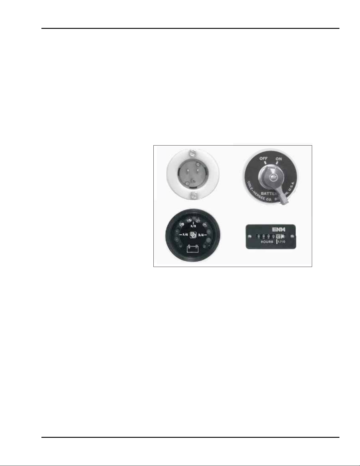
3-1 OPERATOR CONTROLS
Most of the operator controls for the SkyRider 15 are located on the upper and lower
control boxes. Other operator controls include the
gency lowering valve.
base, is the main power disconnect switch for the lift vehicle. The location and operation
of the emergency lowering valve is described in paragraph 3-3.
The BATTERY ON/OFF switch, located on the left side of the lift
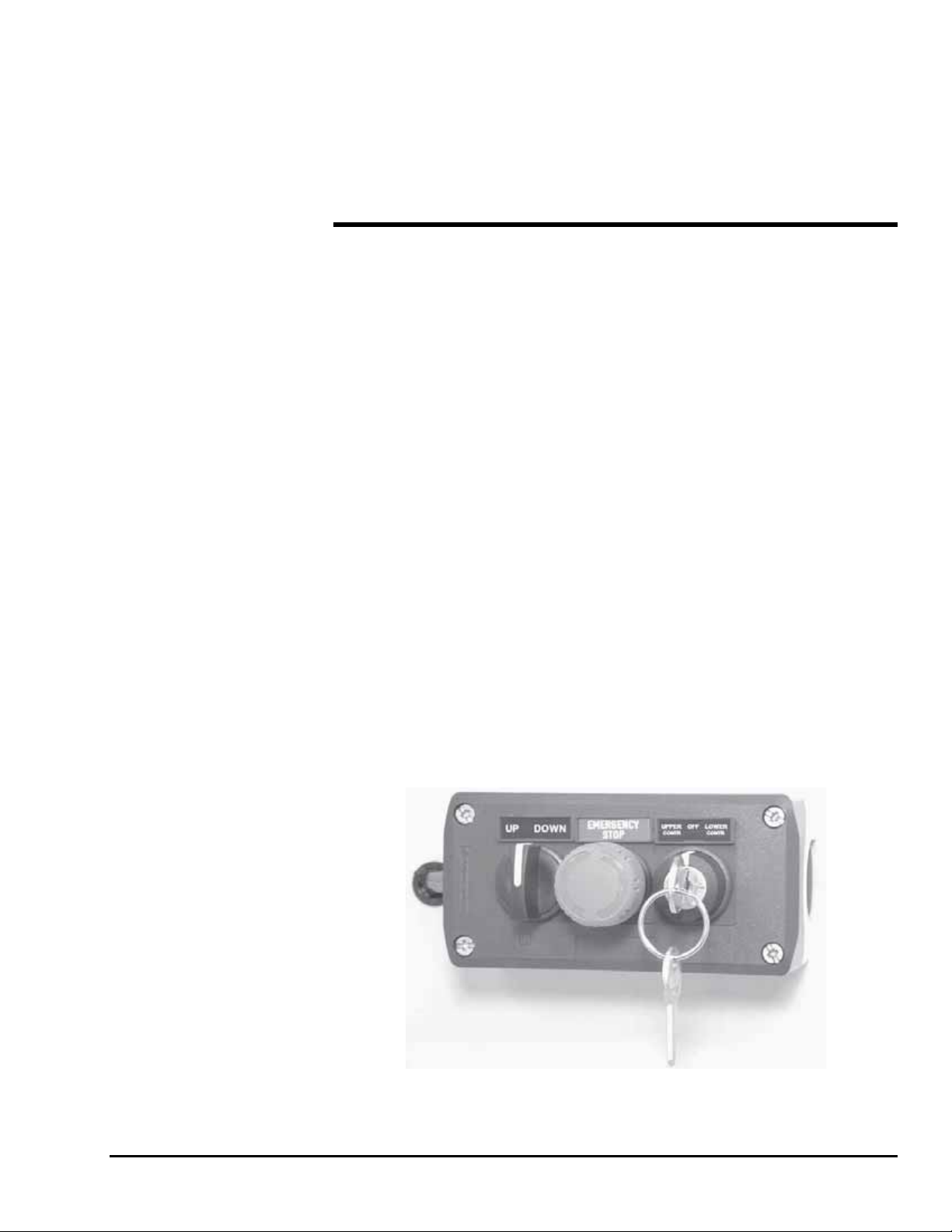
Lower Control Box
The lower control box, Figure 3-1, is located on the lift base and contains three controls:
UP/DOWN, EMERGENCY STOP, and UPPER CONTROL/OFF/LOWER CONTROL. The lower con-
trol box enables lift operations from floor level.
UPPER CONTROL/OFF/LOWER CONTROL key switch selects the active (upper or lower)
The
control location. To enable an
key switch in the
vation from the upper control box, turn the key switch to the
To disable lift vehicle operations, turn the key switch to the
key.
LOWER CONTROL position. To enable lift vehicle travel or platform ele-
UP or DOWN lift motion from the floor, turn and hold the
BATTERY ON/OFF switch and the emer-
UPPER CONTROL position.
OFF position and remove the
Turn the
DOWN position to lower the platform. (The key switch must be held in the LOWER
CONTROL
Press the
moving forward or back, pressing the
causing travel to stop quickly. To resume lift vehicle operation, turn the
STOP
UP/DOWN selector switch to the UP position to raise the lift platform or to the
position to enable the UP/DOWN selector switch).
EMERGENCY STOP button to stop all equipment motion. If the lift vehicle is
EMERGENCY STOP button engages the travel brake
EMERGENCY
button clockwise.
Figure 3-1. Lower Control Box
3-1
Page 18
SkyRider 15
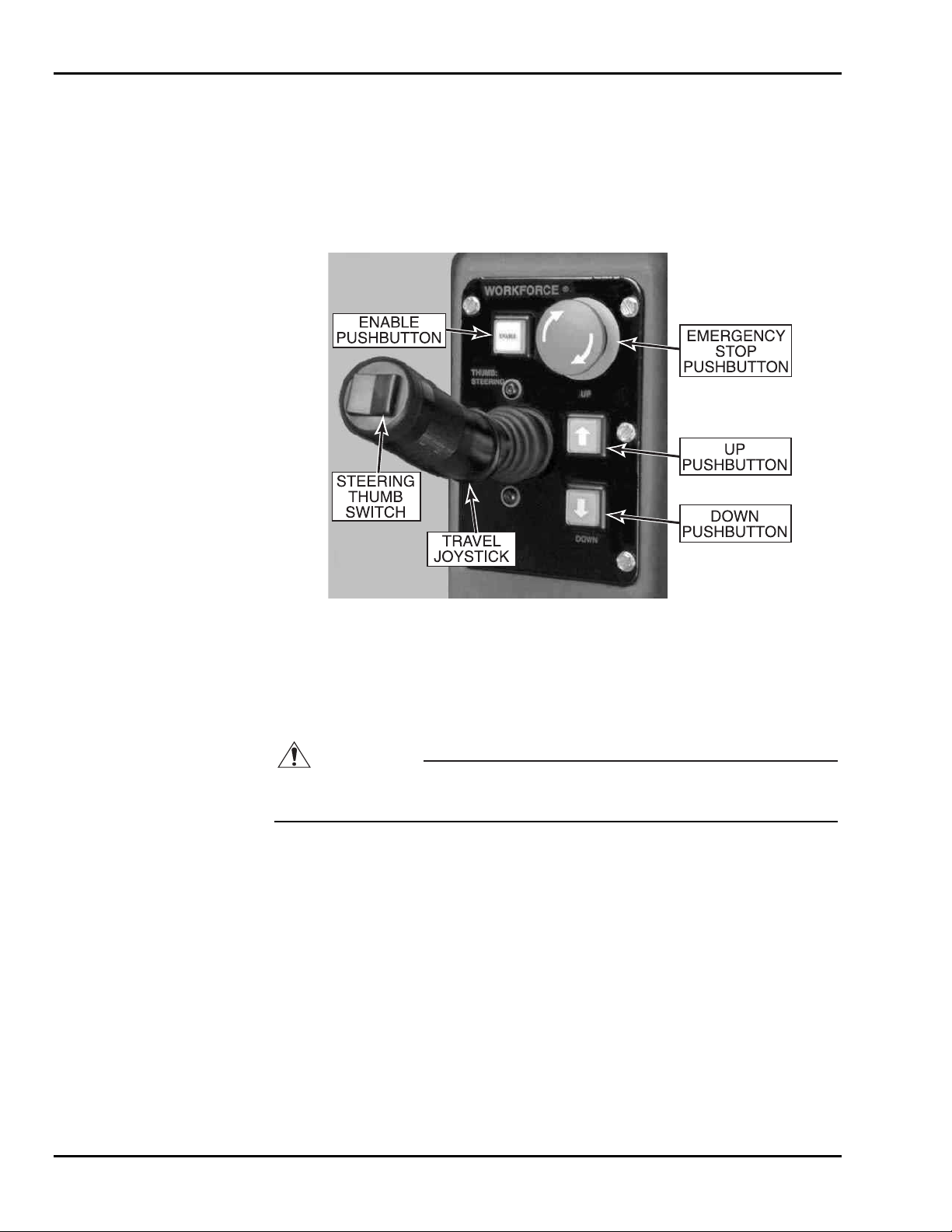
Upper Control Box
The upper control box, Figure 3-2, is in the lift cage. The upper control box enables lift
and travel operations whenever the
lower control box key switch is in the
Upper control box controls include four pushbuttons and a forward/reverse floor-travel
joystick with thumb-switch steering.
BATTERY ON/OFF switch is in the ON position and the
UPPER CONTROL position.
Figure 3-2. Upper Control Box
Press and hold the
ENABLE pushbutton down to enable the control functions. The ENABLE
pushbutton must always be pressed first to enable the lift, steering, and travel functions.
ENABLE pushbutton must be held down to continue the equipment function.
The
CAUTION
The pothole guard actuator will not lift the weight of the SkyRider. Using the pothole guard actuator to lift the vehicle will permanently damage the actuator.
With the ENABLE pushbutton depressed, press the UP [] pushbutton to raise the plat-
form or press the
DOWN [
starts to rise, the pothole guard extends down to near floor level. When extended, the
pothole guard will prevent the lift vehicle from tipping in case a wheel d rops into a hole
during travel. When the lift platform is fully lowered, the pothole guard rises.
With the
ENABLE pushbutton depressed, move the travel joystick forward or back to
move the lift vehicle in the forward or reverse direction. For slow speeds, move the joystick forward or back just a little. For faster speeds, move the joystick more.
With the
ENABLE pushbutton depressed, press the left or right side of the thumb switch to
steer the rear wheels to the left or right. The steering can be adjusted before or during
floor travel.
] pushbutton to lower the platform. When the lift platform
Press the
EMERGENCY STOP button to stop all equipment motion. If the lift vehicle is
moving forward or back, a travel brake is applied causing travel to stop. To resume lift
vehicle operations, turn
3-2
EMERGENCY STOP button clockwise.
Page 19
3 — OPERATION
3-2 NORMAL OPERATING PROCEDURE
Perform the following procedures to operate the SkyRider 15 platform lift vehicle.
1. Read and follow all safety precautions contained in Section 1 and all responsibilities outlined in the ANSI A92.3 reprint in Section 7 of this manual.
2. Position the lift vehicle at the work area. Make sure the vehicle is on a firm and
level surface and that there are no potential hazards such as speed bumps, open
floor drains, potholes, overhead obstructions or electrically charged conductors.
Do not operate the lift vehicle if such hazards exist in the immediate area.
3. Check the lift vehicle for damage or worn parts. If damage or part wear is
found, do not operate the vehicle until the problem is corrected.
4. Turn the
BATTERY ON/OFF switch, Figure 3-3, to the ON position.
Figure 3-3. Battery On/Off Switch
5. Observe the battery charge level indicator. An LED will be lit to indicate the
battery charge level. Verify that the battery charge level is 3/4 or more.
6. Turn the
UPPER CONTROL position.
UPPER CONTROL/OFF/LOWER CONTROL key switch, Figure 3-1, to the
7. Enter the platform cage and close the entry gate. If the gate will be closed when
the lift platform is elevated, you do not have to wear the safety harness. If the
gate will be open while the lift platform is raised, put on the safety harness and
hook it to the
SAFETY HARNESS ATTACHMENT POINT.
8. Use the upper control box controls to operate the lift vehicle.
NOTE: The lift vehicle is equipped with a level sensor. When the vehicle is on a
slope greater than 1 degree, the level sensor disables all functions other
than platform lowering and sounds an alarm beeper. Once the platform
is lowered, floor travel is again enabled to allow travel to a level area.
3-3
Page 20

SkyRider 15
9. During floor travel and lift operations, the alarm beeper should sound. If the
alarm beeper does not work properly, do not operate the lift vehicle.
10. During lift platform descent, the amber caution light should blink on and off. If
the caution light does not blink on and off, do not use the lift vehicle.
11. If any equipment motion continues after the pushbutton, joystick, or selector
switch is released, press the
EMERGENCY STOP pushbutton, Figure 3-2. All
equipment motion should stop immediately.
12. At the end of each workday and whenever a low battery charge level is indicated, transport the lift vehicle to the recharge site and plug in the charge cord.
Verify that the
ON-CHARGING indicator lights up on the battery charger.
NOTE: For more information on battery charging operations, refer to the bat-
tery charging procedure in paragraph 4-4.
13. To shut down the equipment, turn the
switch and the
BATTERY ON/OFF switch to OFF. Remove the key to prevent unau-
thorized equipment operation.
UPPER CONTROL/OFF/LOWER CONTROL key
3-4
Page 21
3 — OPERATION
3-3 EMERGENCY LOWERING PROCEDURES
In an emergency, a person at floor level can lower the platform by holding the UPPER
CONTROL/OFF/LOWER CONTROL
UP/DOWN selector switch to the DOWN position. (If the upper control box emergency
the
stop pushbutton is depressed, the platform will not lower.)
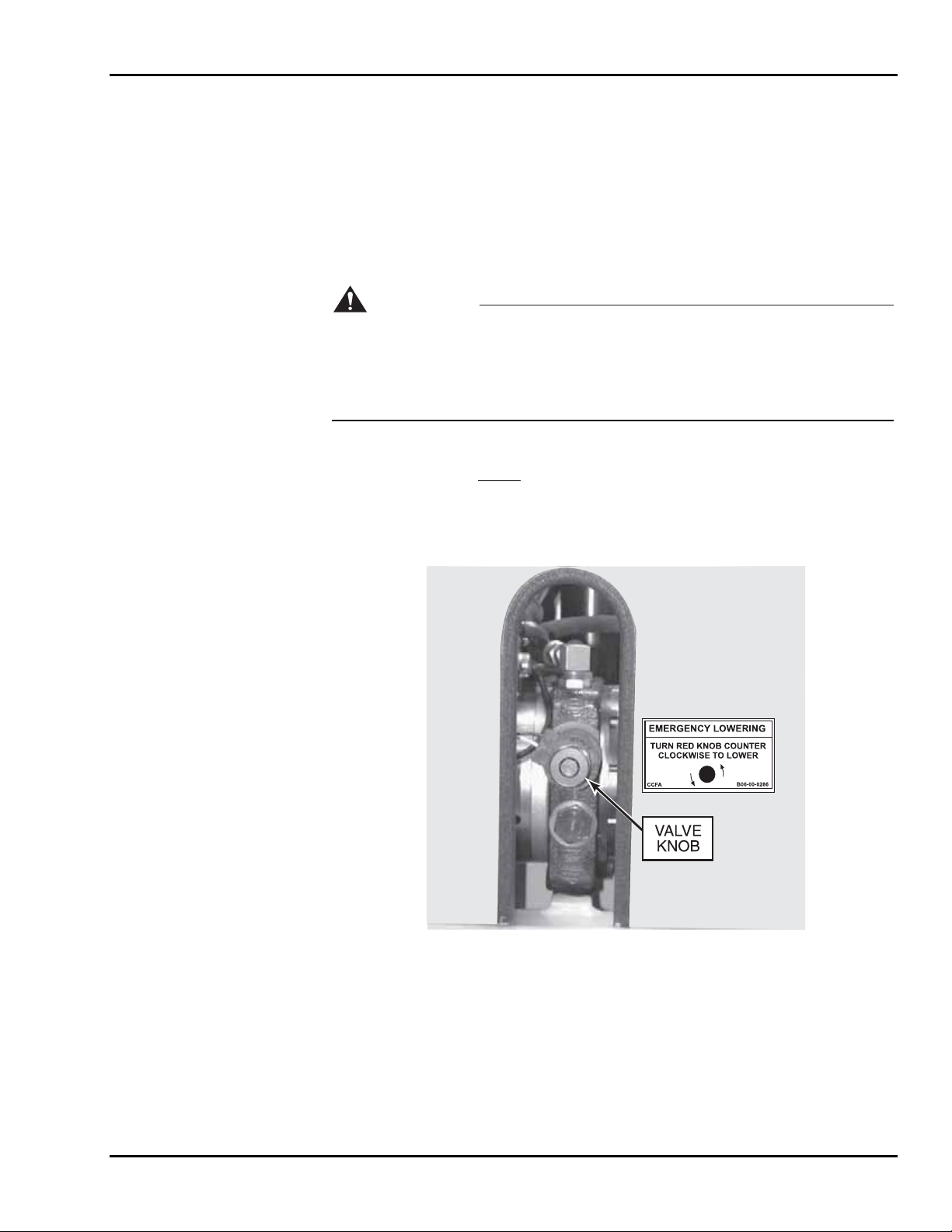
An emergency lowering valve is shown in Figure 3-4. In case of a total loss of battery
power, a person at floor level can safely lower the platform by opening the emergency
lowering valve.
key switch in the LOWER CONTROL position and turning
WARNING
Do not climb out of the lift cage while the lift platform is elevated. The lift mast
cannot be climbed safely. An elevated lift platform has a high center of gravity
and can be tipped easily. Standing on or leaning out from the outside of a cage rail
may cause the lift vehicle to tip over. Tipping the lift vehicle over can cause severe
injury or death and equipment damage.
If you lose power while elevated in the cage, instruct someone else to open the emergency lowering valve. Do not
shelves.
To lower the platform, turn the red valve knob counterclockwise until the platform starts
to descend. When the platform is lowered, turn the valve knob clockwise until closed.
leave the cage to climb down the lift mast or storage
Figure 3-4. Emergency Lowering Valve
3-5
Page 22
SkyRider 15
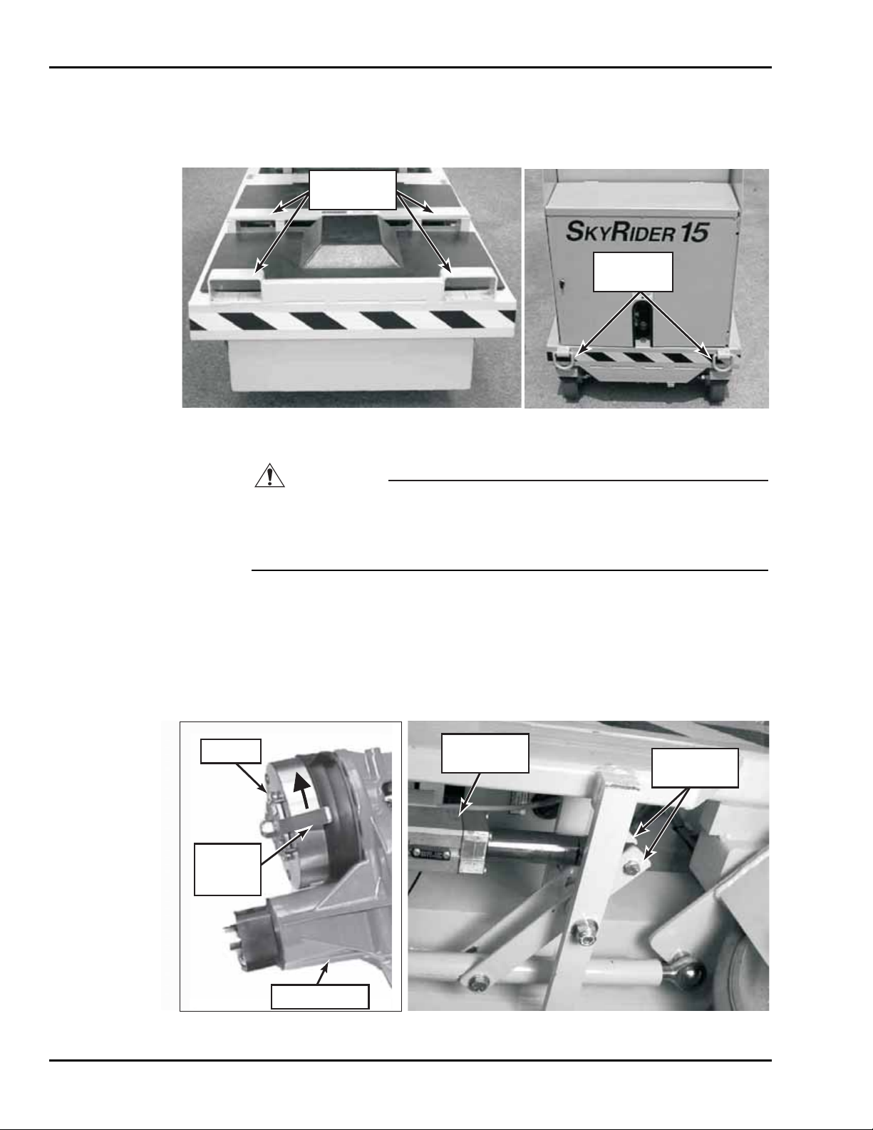
3-4 LIFT VEHICLE TRANSPORT
The platform vehicle is equipped with tie down rings, lifting, and tow features, Figure
3-5. Read the following instructions before using these features to lift or tow the vehicle.
LIFTING
BRACKETS
TIE DOWN
RINGS
Figure 3-5. Lifting Brackets and Tie Down Rings
BRAKE
FREE
WHEEL
LEVER
CAUTION
In the event of power failure, the platform lift vehicle can be towed using the tie
down rings. Do not attempt to push the lift vehicle or use the lift vehicle to pull
another vehicle or object. Pushing the lift vehicle or using the vehicle for towing
may cause serious equipment damage.
The forks of a lift truck (2-ton minimum capacity) can be used to raise the SkyRider for
loading onto a trailer or for blocking up the lift vehicle for maintenance. In case of a battery power failure, the tow clevis can be used to pull the lift vehicle to a service area.
Before towing the SkyRider lift vehicle, you must manually disengage the travel brake
and disconnect the steering linkage. Refer to the illustrations in Figure 3-6.
STEERING
ACTUATOR
STEERING
LINKAGE
TRANSAXLE
Figure 3-6. Travel Brake and Steering Linkage
3-6
Page 23

4
Maintenance
4-1 SCHEDULED SERVICE CHECKS
Daily/Weekly Service Checks
Perform the daily and weekly service checks listed in Table 4-1.
Table 4-1. Daily/Weekly Service Checks
Daily
Service Check
Check that all upper and lower control box controls work
properly.
Check chain assemblies for split leaves, loose pins,
excessive wear, or elongation.
Check for hydraulic oil leaks.
Check for loose or missing parts.
Check for and retighten loose nuts and bolts.
Check that cage gate is secure.
Check that safety harness is in good condition
Verify that cage is securely bolted to lift mast.
Check that slide blocks and their paths are clean and lightly
lubricated with a dry silicone lubricant.
Verify that all safety decals are present and legible.
Ensure Operation Manual is in manual tube.
Check battery electrolyte level.
Check for wear on chain sheaves, sheave axles, and
bearings.
Check caster axle and swivel bolts for wear.
Check casters for cracks or excessive wear.
Lubricate lift chains with 40-weight oil.
before use Weekly
4-1
Page 24

SkyRider 15
Monthly Service Checks
Perform the service checks in Table 4-2 every month, every 6 months, every 12 months,
or every 48 months, as indicated.
Table 4-2. Monthly Service Checks
Service Check
Check hydraulic UP and DOWN
valves operation.
Clean battery terminals.
Check operation of emergency
lowering valve.
Grease rear caster swivel bolts
and axles.
Grease steering linkage pivot
bolts.
Grease front caster pillow blocks.
Grease pivot bolts of pothole
guard actuator linkage.
Every
month
6 months
Every
Every
12 months
Check battery cables and wiring
for loose connections and
damaged wires.
Replace hydraulic oil.
Check slide blocks for wear.
Check for mast sway.
Load test with 500 pounds.
Replace lift chains.
Every
48 months
4-2
Page 25
4 — MAINTENANCE
4-2 LUBRICATION
Lubrication makes operation of the SkyRider 15 more efficient and extends the life of the
lift vehicle. Perform the following lubrication procedures.
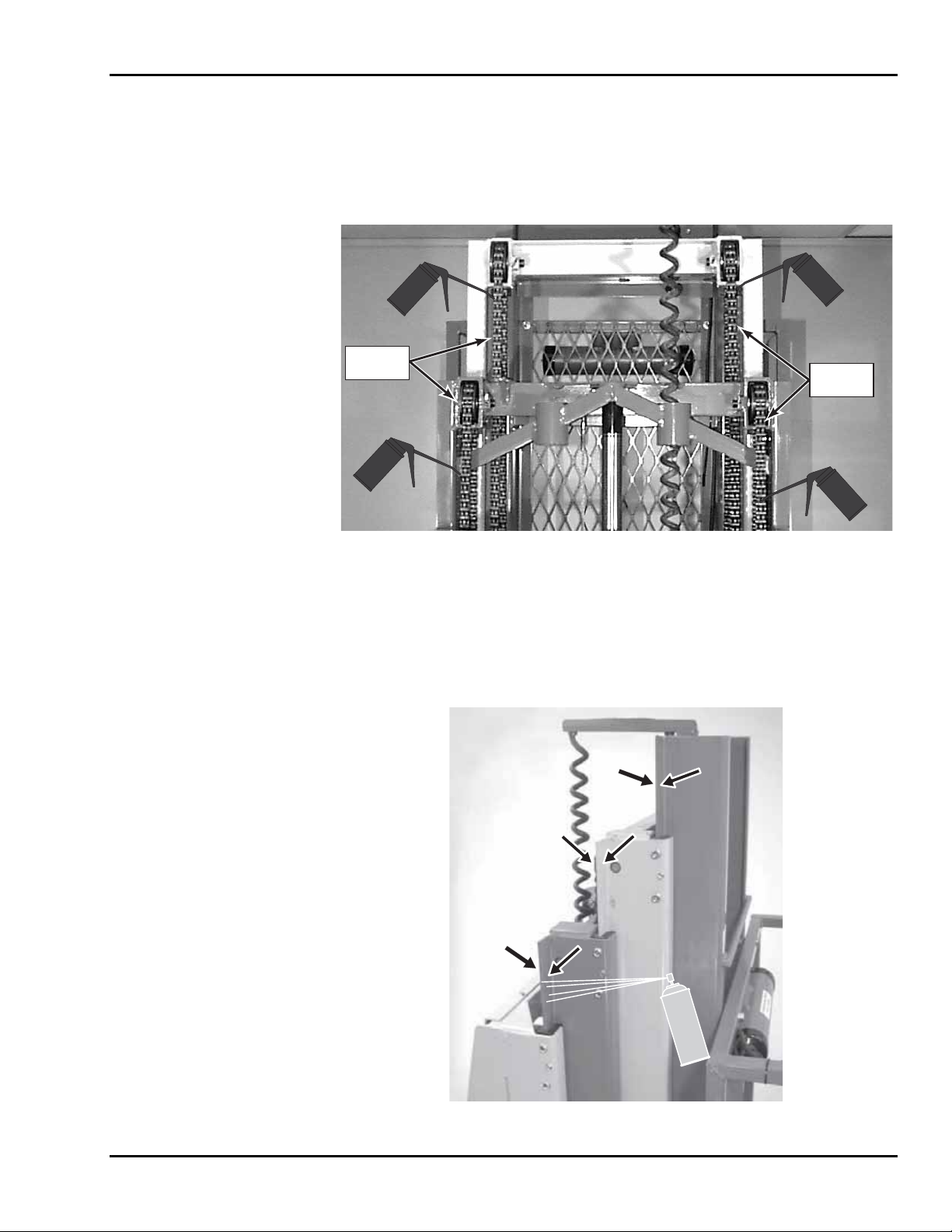
1. Lubricate lift chains with clean 40-weight oil. Refer to Figure 4-1.
LIFT
CHAINS
LIFT
CHAINS
Figure 4-1. Lift Chains Lubrication
2. Clean the mast slide ways, Figure 4-2, and lightly spray the slide ways with a
dry silicone lubricant.
NOTE: The slide blocks have a high level of lubricity and need only be kept
clean. To reduce wear and extend service life, the slide ways should be
cleaned and lightly lubricated with a dry type silicon lubricant.
Figure 4-2. Mast Slide Ways Lubrication
4-3
Page 26
SkyRider 15
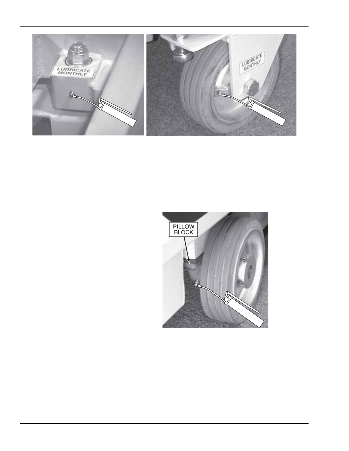
Figure 4-3. Rear Casters Lubrication
3. See Figure 4-3. Grease rear caster axles and swivel bolts at the grease fittings
provided. Add about 1/2 ounce of clean #2 NGLI grease to each fitting.
4. Remove, clean, and lubricate steering linkage and pothole guard linkage bolts
with wheel bearing grease.
5. Apply about 1/2 ounce of clean #2 NGLI grease to the fitting on each front
wheel pillow block, Figure 4-4. Do not over-grease the pillow block bearings.
Figure 4-4. Front Caster Pillow Blocks Lubrication
4-4
Page 27

4 — MAINTENANCE
4-3 HYDRAULIC SYSTEM
Hydraulic system maintenance varies by the amount of use and the environment in which
the lift vehicle is used. Keeping the hydraulic oil clean and th e reservoir properly filled
will help prevent possible damage to the system.
Hydraulic System Inspection
Check all hydraulic hose and fittings for leaks and damage daily. Tighten or replace as
necessary to prevent hydraulic oil loss.
Fluid Check and Replacement
With the platform in its lowest position, the hydraulic oil level should be at the MAXIMUM
level mark (1-1/2 in. from top of reservoir).
The reservoir is initially filled with Energol HLP-HD46 (BP Oil); a high grade, nonfoaming hydraulic oil. This oil is recommended for use in climatic temperatures as low as
-20°F/-29°C. Dextron Automatic Transmission Fluid Type A is recommended for use in
temperatures as low as -40°F/-40°C.
If either of these oils is not available, a good grade SAE 10W hydraulic oil may be used
where the minimum climatic temperature is above 32°F/0°C. An SAE 5W hydraulic oil
may be used where temperatures are as low as 0°F/-18°C.
Do not mix different hydraulic oils. Clean the reservoir and sump strainer and replace the
hydraulic oil at least once a year. Clean the reservoir and sump strainer and replace the
oil whenever contamination is suspected.
Hydraulic System Air Bleeding Procedure
Delayed response or uneven movement of the hydraulic cylinder may indicate trapped air
in the hydraulic oil.
NOTE: Whenever the upper control box emergency stop pushbutton is engaged,
lift operation remains enabled at the lower control box. However, the
DOWN lift motion will be intermittent. Intermittent lift motion should
or
not be mistaken as trapped air in the hydraulic system.
Perform the following procedure to bleed trapped air from the hydraulic system.
1. Fill the reservoir to the
2. Fully raise the lift platform.
3. Lower the lift platform to allow oil with entrapped air to return to the reservoir.
Be careful not to overflow the hydraulic reservoir.
4. Leave the lift platform down and the lift vehicle at rest for 10 to 15 minutes
while air escapes the hydraulic oil.
5. Repeat steps 2 through 4 as needed. Each time the platform is lowered, refill the
reservoir to prevent pumping more air into the hydraulic cylinder.
MAXIMUM level with the proper hydraulic fluid.
UP
4-5
Page 28
SkyRider 15
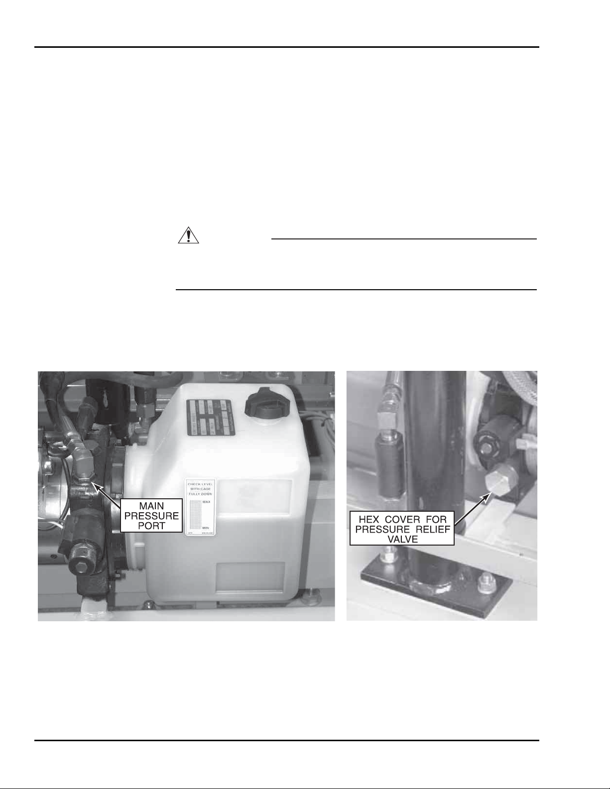
Pressure Relief Valve Adjustment
Perform the following procedure to adjust the pressure relief valve. Refer to Figure 4-5.
1. Move the SkyRider lift platform to the fully
DOWN position.
2. Center 500 pounds of weight on the lift platform.
3. Remove the hex cover from the pressure relief valve. The pressure relief valve
is on the back side of the pump.
th
4. Turn the pressure relief valve adjust screw 1/8
turn counterclockwise. This will
adjust the relief valve bypass pressure setting for less than 500 pounds of lift.
5. Place the key switch in the
LOWER CONTROL position and press the UP pushbut-
ton. The pump should run, bypassing oil to the hydraulic reservoir.
CAUTION
Do not adjust the pressure relief valve for a bypass pressure higher than needed to
raise the 500 pound load. Hydraulic system overload may occur at a higher bypass
pressure, causing hydraulic failures or damage to the equipment.
6. With the platform lift function enabled (pump running), turn the pressure relief
valve adjust screw clockwise just enough to smoothly raise the platform without
bypassing oil to the hydraulic reservoir.
7. Reinstall the hex cover over the pressure relief valve.
Figure 4-5. Pressure Relief Valve Adjustment
4-6
Page 29
4 — MAINTENANCE
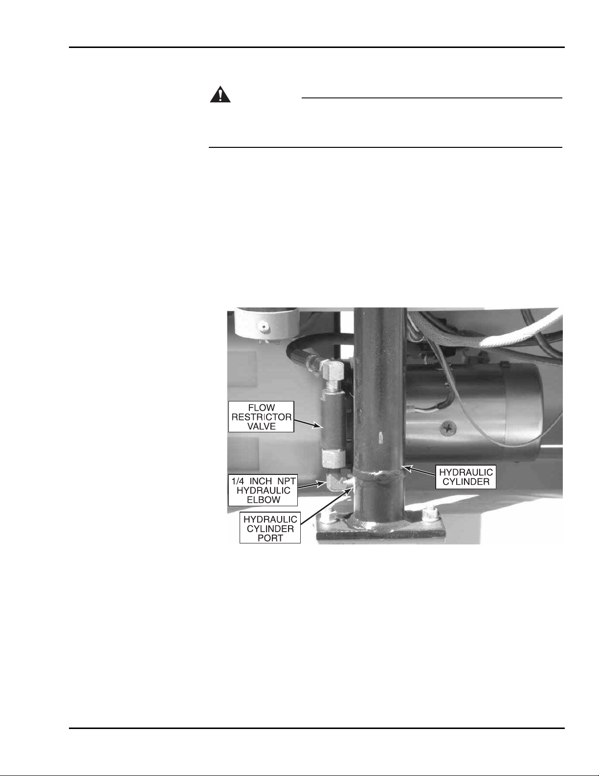
Flow Restrictor Valve Replacement
WARNING
Closely read and adhere to the following instructions whenever you remove and
install the flow restrictor valve. Failure to properly install the flow restrictor valve
can result in serious injury or death to personnel or damage to the equipment.
If the flow restrictor valve, Figure 4-6, needs to be removed or replaced, it is important
that it be properly reinstalled. The valve will be marked either with an arrow or with the
word “IN”.
If marked with an arrow, the arrow must point away from the hydraulic cylinder port. If
marked with the word “IN”, the end of the valve marked “IN” must be toward the hydraulic cylinder port.
Only a 1/4 inch NPT hydraulic elbow fitting should be connected between the hydraulic
cylinder port and the flow restrictor valve. Improper installation of the flow restrictor
valve or use of the wrong size hydraulic elbow fitting will allow varying rates of descent
and may result in near free-fall in case of hydraulic hose failure.
Figure 4-6. Flow Restrictor Valve
4-7
Page 30
SkyRider 15
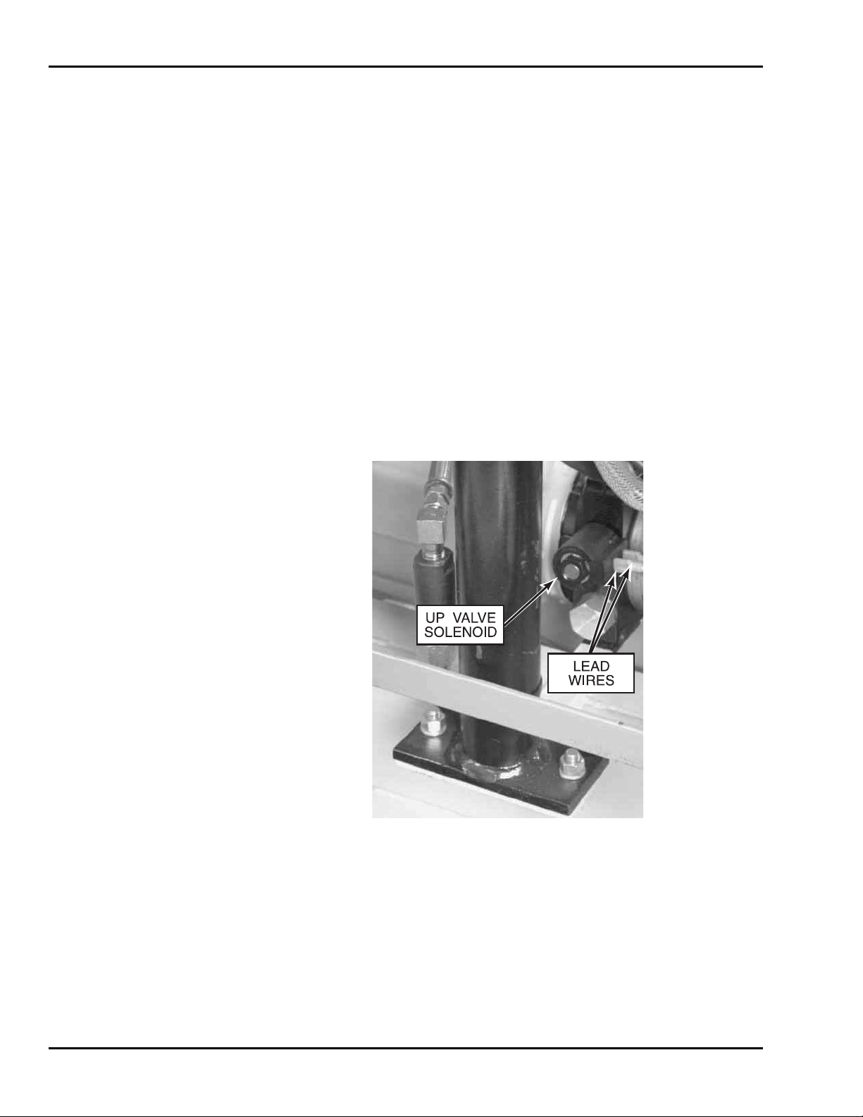
Up Valve Operation Check
Refer to the hydraulic diagram in Figure 4-14. The normally-open Up valve routes oil
flow from the hydraulic pump to the reservoir. Pressing the
energizes the Up valve. Oil flow to the reservoir is shut off, causing the lift cylinder to
extend. Releasing the
ENABLE or UP pushbutton causes the Up valve to open, routing all
hydraulic oil to the reservoir. Even if the hydraulic pump motor should continue to run,
the lift platform will not rise when the
ENABLE or UP pushbutton is released.
This fail-safe operation is defeated only if the Up valve sticks in the closed position . A
sticking valve and fused pump-start relay contacts would cause the lift platform to rise,
even after the
UP pushbutton is released. This would be an unsafe operating condition.
The following operation check indicates whether or not the Up valve is sticking:
1. Disconnect the lead wires from the Up valve solenoid, Figure 4-7.
ENABLE and UP pushbuttons
2. At the lower control box, hold the key switch in the
and press the
UP pushbutton. The hydraulic pump motor should run without rais-
LOWER CONTROL position
ing the lift platform.
3. If the lift platform rises, the Up valve is sticking closed. Remove and clean or
replace the sticky valve.
4. Reconnect the lead wires to the Up valve solenoid.
Figure 4-7. Up Valve Operation Check
4-8
Page 31

4 — MAINTENANCE
Hydraulic Cylinder Repair
CAUTION
Hydraulic cylinder removal requires extensive disassembly of the SkyRider 15 lift
vehicle. Contact Workforce for assistance before removing the hydraulic cylinder.
Hydraulic Cylinder Removal
It is recommended that Workforce be contacted for assistance before removing the hydraulic cylinder.
1. Make sure hydraulic cylinder is completely retracted and pressure is released
from the system. Place a pan underneath the cylinder to catch the hydraulic oil.
2. Disconnect the hydraulic hose from the flow restrictor valve and drain the hydraulic oil from the cylinder. Remove the two bolts, washers, and nuts securing
the hydraulic cylinder to the base.
3. Remove the plexiglass cover from the base.
4. Remove the mounting bolt, washer, and nut securing hydraulic cylinder to the
lower mast.
5. Disconnect the two lift chains from the base mast.
6. Using a crane with at least one ton of lifting capacity, lift the lower mast section
high enough to remove the clamp securing the cylinder to the base. Remove the
clamp and cylinder from the unit.
7. After hydraulic cylinder maintenance is completed, reinstall the cylinder in the
reverse order of removal.
4-9
Page 32
SkyRider 15
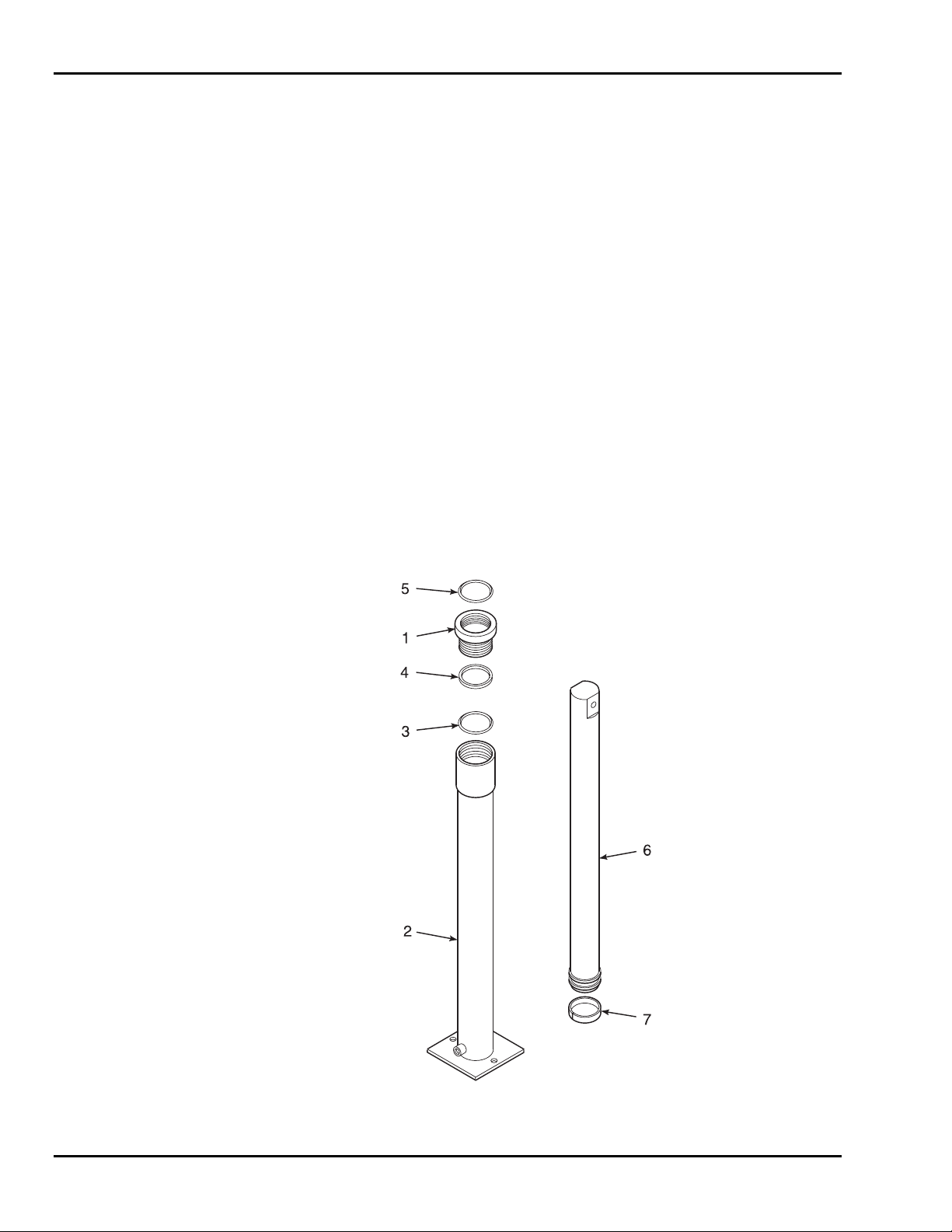
Hydraulic Cylinder Repair Procedure
Perform the following procedure to repair the hydraulic lift cylinder. Refer to Figure 4-8.
1. Remove gland nut (1) from cylinder jacket (2). If worn, replace gland nut (1),
o-ring (3), packing ring (4), and rod wiper (5) with a new gland nut assembly.
2. Remove piston rod (6) and wear ring (7).
3. Inspect piston rod (6) and wear ring (7) for gouges, scratches, and wear. Replace worn or damaged components.
4. Thoroughly clean the inside surface of cylinder jacket (2).
5. Lubricate wear ring (7) with clean hydraulic oil or petrolatum. Slide piston rod
(6) with wear ring (7) into cylinder jacket (2).
6. Lubricate o-ring (3), packing ring (4), and rod wiper (5) with clean hydraulic oil
or petrolatum.
7. Slide gland nut (1) onto piston rod (6). Fully thread the gland nut into cylinder
jacket (2).
8. Reinstall the hydraulic cylinder in the lift vehicle and reconnect the hydraulic
hose.
9. Refill the hydraulic reservoir.
10. Stroke the cylinder to seat and align packing ring (4) and wear ring (7).
11. Bleed all trapped air from the hydraulic system.
1. Gland Nut
2. Cylinder Jacket
3. O-ring
4. Packing Ring
5. Rod Wiper
6. Piston Rod
7. Wear Ring
Figure 4-8. Hydraulic Cylinder Disassembly
4-10
Page 33
4 — MAINTENANCE
4-4 ELECTRICAL SYSTEM
Regular maintenance is necessary to keep the electrical system in proper working order.
Check daily all electrical wires for cuts, broken wires, potential short circuits, and any
other damage.
Battery Care and Charging
The electric system is designed to provide power for a normal work shift. However, the
charge life of the battery pack depends on machine usage. Plan your work to prevent unnecessary use of electrical power.
Since the power source for the machine is a battery pack, proper battery care is important. Recharge the batteries after each work shift. When the machine is not being used,
the batteries should be charged at least once a week. Normal battery charging time
should be 10 to 12 hours. If the battery is extremely low, charging time may be as long as
24 hours.
Clean the battery terminals monthly. Remove the cables from the battery posts, clean the
battery posts and cable ends to shiny metal, and replace the cables. Always connect the
insulated cable from the starter solenoid to the most positive post. Lubricate the outside
of the battery post connections with petroleum jelly or grease.
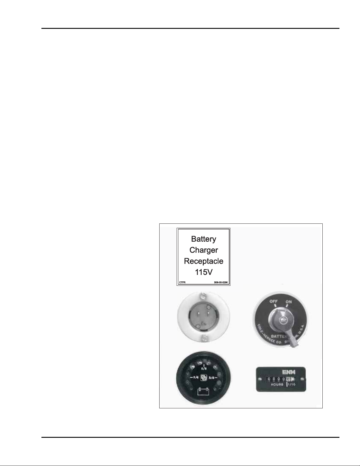
Battery Charging Procedure
1. Connect a heavy-duty extension cord (10AWG, minimum) from a 110V AC,
60 Hz outlet to the battery charger receptacle, Figure 4-9. The extension cord
should be as short as possible to reduce voltage drop.
Figure 4-9. Battery Charger Receptacle
4-11
Page 34
SkyRider 15
2. When there is power to the battery charger, a red “ON-CHARGING” LED on
the charger will be lit and the ammeter will display the rate of charge.
3. Once the battery voltage reaches a predetermined level programmed in the electronic control, the yellow “80% CHARGE” LED will illuminate.
4. The charge will be completed 3-1/2 hours after the yellow “80% CHARGE”
LED is lit. The charger and all LED’s will automatically shut off. The battery
charge level indicator, Figure 4-9, should indicate at least 3/4 charge.
NOTE: If the battery voltage does not reach the 80% level within 14 hours, the
charger will shut off and the “CHECK BATTERY” LED will light up.
CAUTION
Before making or breaking connections between charger and battery, always remove the power cord from the 110 volt AC outlet. Always check the battery electrolyte level and add water after charging the battery. For more information, refer to the instructions supplied with the battery charger.
5. Unplug the extension cord from the battery charger receptacle.
4-5 LIFT CHAINS AND SLIDE BLOCKS
WARNING
Do not operate a unit on which any chain assembly is damaged or in need of replacement. Operating a unit with a damaged chain can cause severe injury or
death to personnel and damage to equipment.
Inspect all lift chains daily. Inspect for signs of wear, split leaves, loose pins, clevis damage, and elongation. Replace any chain that is damaged in any way. Chain assemblies
may be ordered from your dealer or direct from the factory. Do not operate a unit on
which any chain assembly is damaged and in need of replacement.
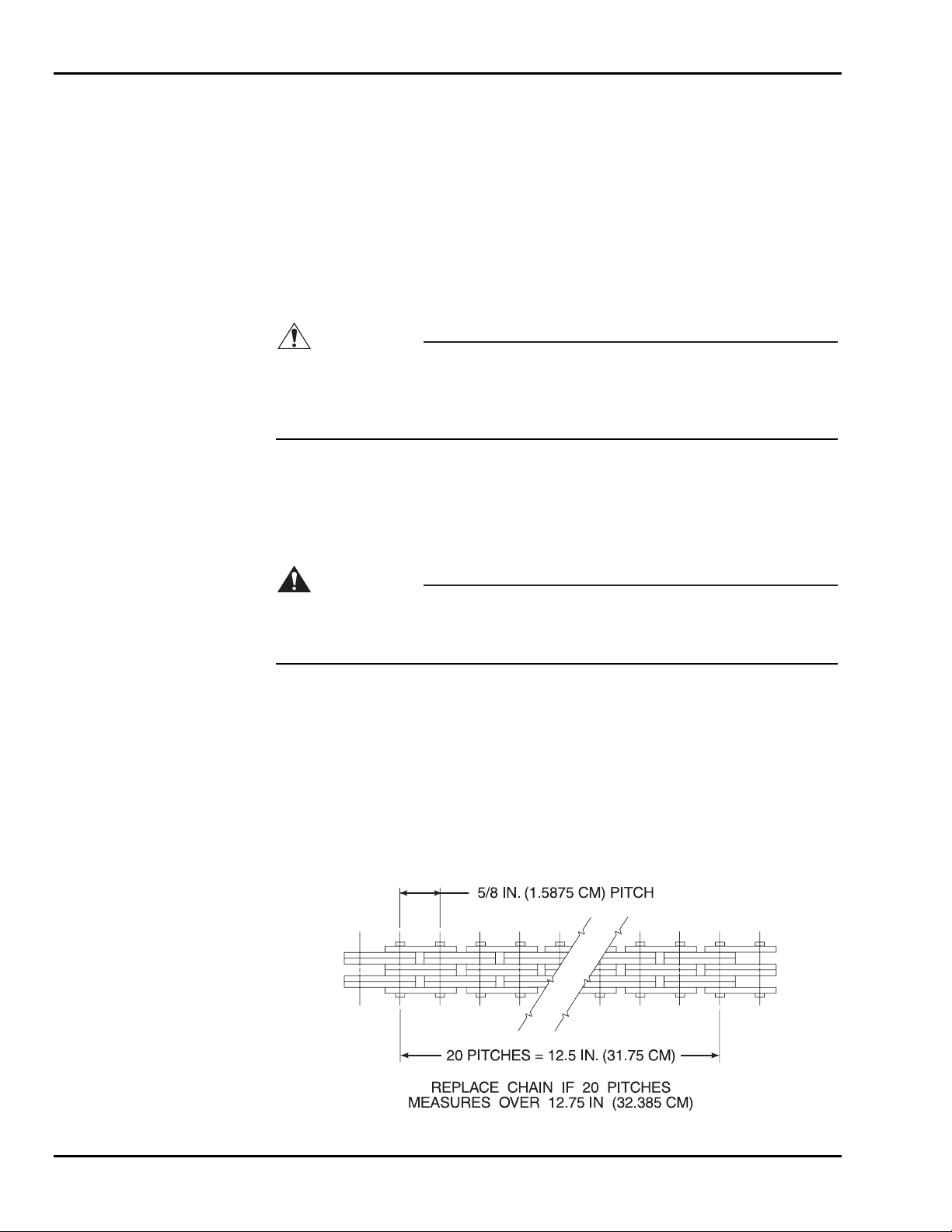
Chain Elongation Inspection
Refer to Figure 4-10. Measure 20 pitches of chain. Twenty pitches of new chain should
measure 12.5 in. (31.75 cm). Replace the chain if a 20-pitch length measures over 12.75
in. (32.385 cm).
Figure 4-10. Chain Elongation Inspection
4-12
Page 35
4 — MAINTENANCE
NOTE: The lift chains should be replaced every four years unless damage or
wear requires earlier replacement.
Lift Chain Adjustment
1. Raise the platform to the maximum height. Then, lower the platform while
someone verifies that all sheaves (pulleys) are turning and that the chains are not
visibly damaged or worn.
2. Remove the plexiglass cover from the base.
3. When the platform is fully lowered, the lift chains should be equally tight.
Check each lift chain at mid-span. The lift chains should flex about 1/2 to 3/4
inch (12 to 19 mm), but there should be no loose play.
4. If a lift chain is loose, tighten the related clevis, Figure 4-11. Tighten the clevis
lock nut until the lift chain just becomes snug. Do not over-tighten any lift
chain. (An over-tightened lift chain will raise the platform from its rest position
at the bottom of the base slide ways).
5. After making a lift chain adjustment, verify that at least 1/8 in. (3 mm) of the
threaded clevis rod extends beyond the lock nut. Also recheck the slack of all
lift chains at mid-span; verify that all lift chains are equally snug.
6. If a single lift chain requires frequent adjustment, the clevis lock nut is probably
worn. Replace any clevis lock nut that does not hold position during use.
7. Replace the plexiglass cover.
LIFT
CHAINS
CLEVIS
LOCK
NUT
Figure 4-11. Lift Chains Adjustment
LIFT
CHAINS
CLEVIS
LOCK
NUT
4-13
Page 36
SkyRider 15
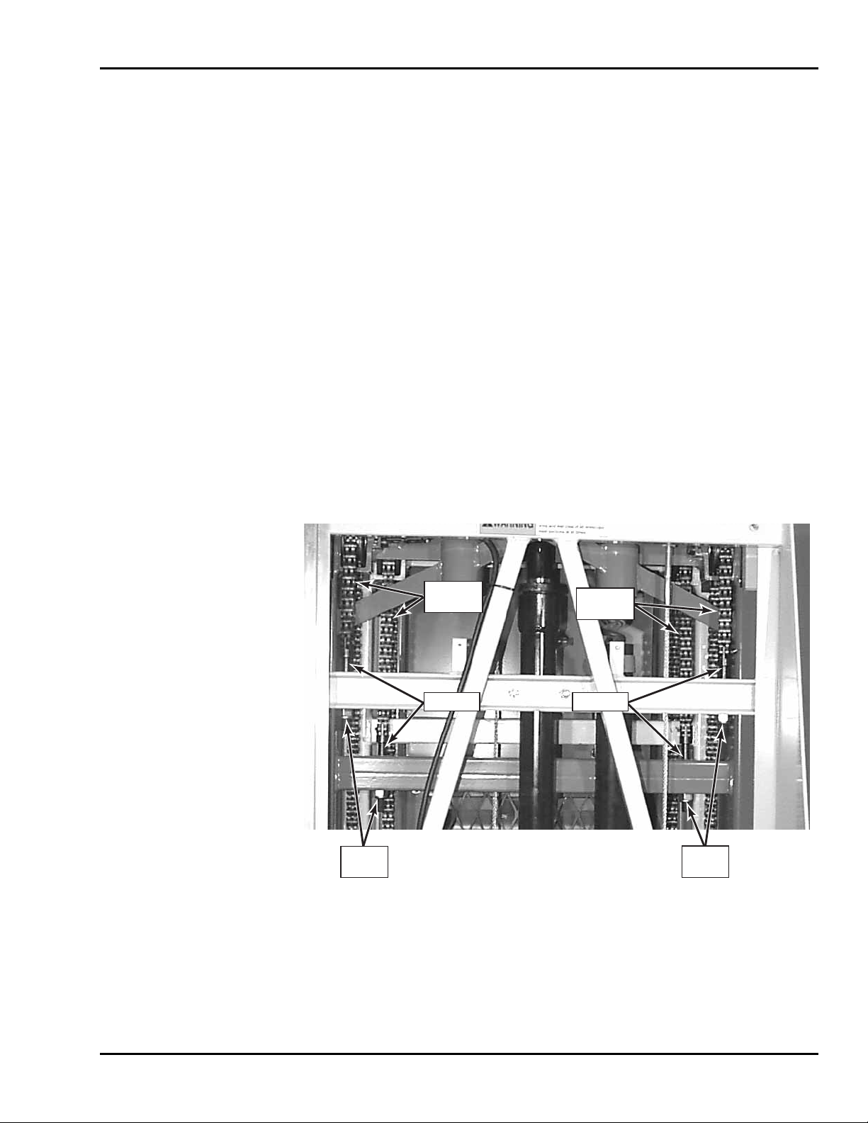
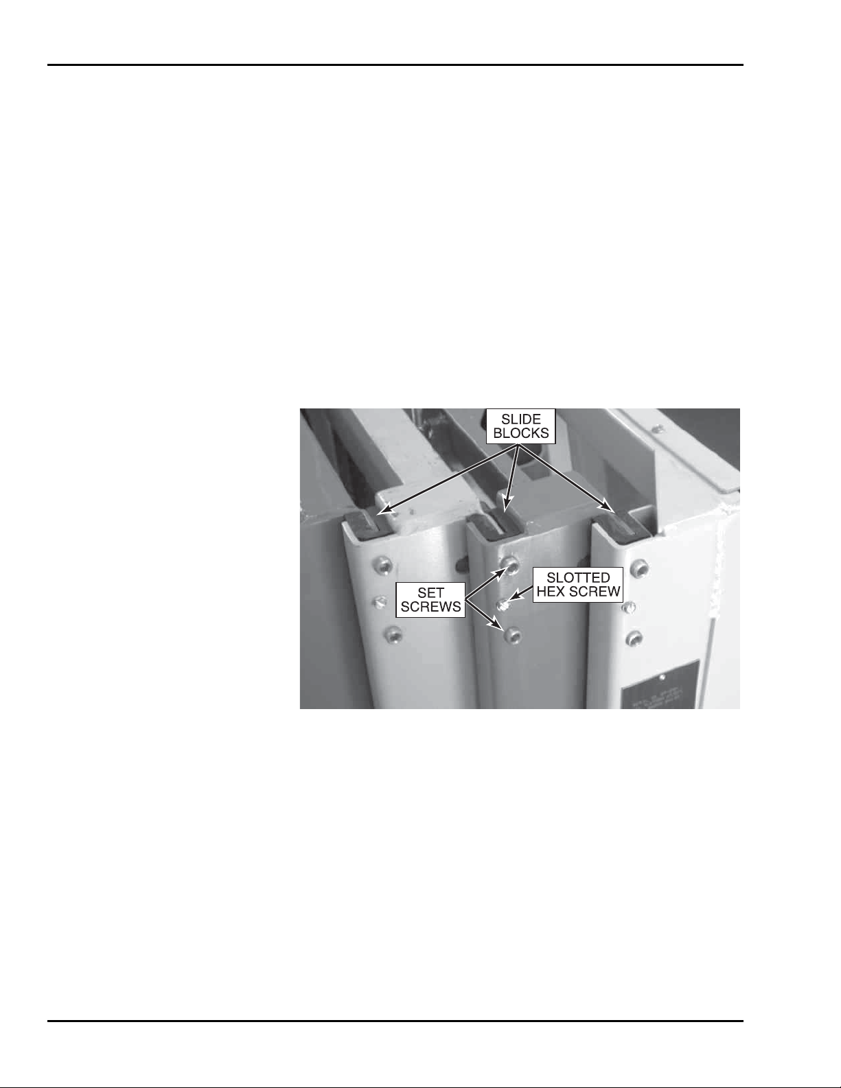
Slide Block Adjustment
Annually check for wear on the slide blocks and replace or retighten as necessary. If the
lift exhibits excessive mast sway, it is probable that the slide blocks need adjustment. The
slide blocks should be adjusted so that there is no air gap between the slide block and the
mast the slide block is moving against. There are 12 slide blocks, - 6 upper and 6 lower.
Three upper slide blocks are shown in Figure 4-12.
Start with the slide blocks on one side of the inner mast. Adjust the upper and lower slide
blocks on one side, followed by the upper and lower slide blocks on the opposite side.
Repeat the adjustments for the center mast slide blocks, followed by the outer mast slide
blocks. The adjustment procedure is the same for all slide blocks:
1. Loosen, but do not remove the slotted hex screw securing the slide block.
2. Use an Allen wrench to turn the set screws clockwise. This will push the block
in against the next mast. Do not overtighten. Tighten the slotted hex head screw
to secure the slide block in position.
3. After all adjustments are made, fully extend the lift. If the platform can be raised
and lowered without hesitation or stopping, the blocks are properly adjusted.
Figure 4-12. Slide Blocks Adjustment
NOTE: The plastic slide blocks in the mast are made of a bearing material which
has a high degree of lubricity and need only be kept clean. However,
precautions should be taken to ensure that the paths along which the
blocks move are kept clean and lightly lubricated with a dry type silicon
lubricant.
4-14
Page 37

4 — MAINTENANCE
4-6 TROUBLESHOOTING
Table 4-3. Troubleshooting Chart
Problem Cause Correction
1. Lift vehicle controls do not
work at upper or lower control box.
a. Master power switch turned off.
b. Low battery power or faulty battery
circuit.
c. Emergency stop button engaged
(pushed in).
d. Battery ground or in-series battery
cable loose.
e. Circuit breaker tripped.
f. Battery cable or equipment ground
lead loose or corroded.
a. Turn on master power switch.
b. Recharge batteries per paragraph 4-4.
Check for faulty battery or cables if
red battery charger LED is lit.
c. Rotate emergency stop buttons clock-
wise to disengage.
d. Check for and repair loose battery
connections or ground fault.
e. Reset breaker. If breaker trips again,
locate and correct short to ground in
power circuit wiring.
f. Clean and reconnect loose or cor-
roded battery cable or ground lead.
2. Lift vehicle controls do not
work at upper control box,
but do work at lower control
box.
3. When UP function is se-
lected, pump motor runs but
will not raise the platform.
a. Emergency stop button engaged
(pushed in) on upper control box.
b. Upper control box cable connectors
unplugged.
c. Upper control box cable connectors
plugged into wrong receptacles.
d. Enable pushbutton switch or wiring
faulty.
a. Hydraulic oil level low in reservoir.
b. More than 500 lbs. on lift platform.
c. Emergency lowering valve open.
d. Up valve solenoid or solenoid wiring
faulty.
e. Down valve sticking open or leaking.
f. UP switch or UP switch wiring faulty.
g. Mast sections dirty; slide blocks
binding.
h. Internal leakage in hydraulic cylinder.
a. Rotate emergency stop buttons clock-
wise to disengage.
b. Plug in cable connectors at front of
upper control box.
c. Plug in cable connectors in opposite
receptacles at upper control box.
d. Repair wire break or replace faulty
switch.
a. Check reservoir level. If low, check
for oil system leakage. Refill reservoir
and bleed air from hydraulic system
per instructions in paragraph 4-3.
b. Ensure load is 500 lbs. or less.
c. Close emergency lowering valve.
d. Check voltage at up valve solenoid. If
no voltage, check wiring. If voltage,
exchange solenoids and recheck func-
tion; replace solenoid if faulty.
e. Repair or replace down valve.
f. Check for lighted UP LED when up
switch is engaged. If LED does not
light, signal is not reaching main con-
troller; repair wire break or replace
faulty switch.
g. Clean and lubricate masts with dry
silicone. If needed, adjust slide bocks
per paragraph 4-5.
h. Check cylinder housing for heat
buildup due to leakage. If leakage is
indicated, repair or replace hydraulic
cylinder.
4-15
Page 38

SkyRider 15
Table 4-3. Troubleshooting Chart (Continued)
Problem Cause Correction
4. ENABLE pushbutton blinks
when pressed.
a. ENABLE pushbutton has been
pressed down for longer than 5
a. Release ENABLE pushbutton and
press again.
seconds without a function being
selected.
b. Joystick potentiometer out of adjust-
ment (will not return to center).
b. Adjust joystick forward/reverse travel
potentiometer for null drive signal
with joystick at center.
c. Did not press ENABLE pushbutton
first before moving joystick to for-
c. Release ENABLE pushbutton and
press again before moving joystick.
ward or reverse drive.
5. When DOWN function is
selected, lift platform will
not descend.
d. Tried to drive forward or reverse and
raise or lower the platform at the
same time.
a. Down valve solenoid or solenoid
wiring faulty.
b. Down valve sticking; does not open.
c. DOWN switch or DOWN switch
wiring faulty.
d. Release ENABLE pushbutton and run
only one function (drive or lift) at a
time.
a. Check voltage at down valve sole-
noid. If no voltage, check wiring. If
voltage, exchange solenoids and recheck function; replace solenoid if
faulty.
b. Repair or replace down valve.
c. Check for lighted DOWN LED when
down switch is engaged. If LED does
not light, signal is not reaching main
controller; repair wire break or re-
place faulty switch.
6. Alarm is sounding; lift UP
and travel functions stopped
a. Lift vehicle more than 1 degree out of
level.
a. Lower lift platform and drive lift
vehicle to level area.
working.
7. When joystick is moved, lift
vehicle will not travel.
a. Wheels blocked.
b. Free wheel lever in free wheel (tow)
position.
c. Joystick or joystick wiring faulty.
d. Main controller or main controller
signal wiring faulty.
e. Motor controller 24-volt power cable
disconnected.
a. Check wheels for blocking; remove
travel obstacle.
b. Move free wheel lever back to drive
position.
c. Check for lighted travel LED when
joystick is engaged. If travel LED
does not light, travel signal is not
reaching main controller; repair wire
break or replace faulty joystick.
d. Check for output voltage to motor
controller when joystick is engaged.
If travel signal is not present at main
controller, contact Workforce for assistance. If travel signal is not present
at motor controller, repair wire break.
e. Check connection of 24-volt power
cable to motor controller; repair faulty
power cable connection.
4-16
Page 39

4 — MAINTENANCE
Table 4-3. Troubleshooting Chart (Continued)
Problem Cause Correction
7. When joystick is moved, lift
vehicle will not travel. (cont)
f. Motor controller, motor controller
output wiring, or transaxle drive motor faulty.
g. Transaxle drive train damaged.
f. Check for output voltage to drive
motor when joystick is engaged. If
drive voltage is not present at motor
controller, replace motor controller. If
drive voltage does not reach drive
motor, repair wire break. If drive voltage is present at drive motor, replace
drive motor.
g. If transaxle drive motor runs, inspect
drive train components for damage.
Repair or replace transaxle gearhouse,
if damaged.
8. Wh en steering thumb switch
is pressed, steering wheels
do not swivel.
9. Pothole guard does not
deploy when lift platform is
raised via upper control box.
a. Wheels turned to steering limit.
b. 10 Amp Motors fuse burned out on
main controller board.
c. Internal steering actuator fuse.
d. Thumb switch or thumb switch wiring
faulty.
e. Actuator or actuator wiring faulty.
f. Steering linkage failed.
g. Main controller faulty.
a. 10 Amp Motors fuse burned out on
main controller board.
b. Internal steering actuator fuse.
c. Actuator or actuator wiring faulty.
d. Down limit switch or limit switch
wiring faulty.
e. Pothole guard linkage failed.
f. Main controller faulty.
a. Turn wheels in opposite direction.
b. Replace 10 Amp Motors fuse.
c. Replace steering actuator fuse.
d. Check for lighted steering LED when
thumb switch is engaged. If LED does
not light, signal is not reaching main
controller; repair wire break or replace faulty joystick.
e. Check actuator wiring for operating
voltage. If voltage is present, replace
faulty actuator. If voltage is not present, check actuator wiring for continuity; repair wire breaks.
f. Check steering linkage for damage;
replace damaged parts.
g. Contact W orkforce for assistance.
a. Replace 10 Amp Motors fuse.
b. Replace steering actuator fuse.
c. Check actuator wiring for operating
voltage while platform is rising. If
voltage is present, replace faulty ac-
tuator. If voltage is not present, check
actuator wiring for continuity; repair
wire breaks.
d. Check limit switch operation and
wiring. Replace damaged limit switch
or repair wiring.
e. Check pothole guard linkage for
damage; replace damaged parts.
f. Contact Workforce for assistance.
4-17
Page 40
SkyRider 15
Table 4-3. Troubleshooting Chart (Continued)
Problem Cause Correction
10. Pothole guard does not rise
when lift platform is lowered
via upper control box.
11. When BATTERY ON/OFF
switch is turned ON, hydrau-
a. 10 Amp Motors fuse burned out on
main controller board.
b. Internal steering actuator fuse.
c. Actuator or actuator wiring faulty.
d. Pothole guard linkage failed.
e. Main controller faulty.
a. Motor start relay failure; relay con-
tacts fused shut.
a. Replace 10 Amp Motors fuse.
b. Replace steering actuator fuse.
c. Check actuator wiring for operating
voltage when platform reaches lower
travel limit. If voltage is present, replace faulty actuator. If voltage is not
present, check actuator wiring for
continuity; repair wire breaks.
d. Check pothole guard linkage for
damage; replace damaged parts.
e. Contact Workforce for assistance.
a. Replace motor start relay.
lic pump starts up.
Troubleshooting Aids
EASI-0
EASI-TXD
Pothole Up
Motor
EASI-24
EASI-RXD
F1 2AMP
Pothole Down
Steer Left
Pothole
Motor
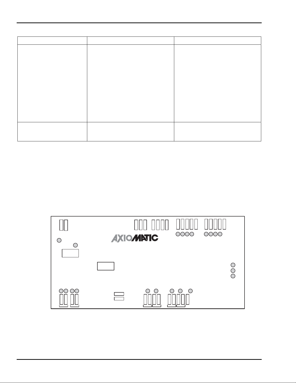
See Table 4-4 for interpreting LED indicators located on the main controller board
shown in Figure 4-13. Hydraulic and PC logic diagrams are shown in Figures 4-14 and
4-15. An electrical wiring diagram is shown in Figure 4-16.
Upper Controls
Lower Down
Steer Right
Steering
F2 10AMP
GND
TXD
TECHNOLOGIES CORPPORATION
P/N: EASI-WFC-02
MAIN CONTROLLER
POS 24V
NEG 24V
CAN L
RXD
Down Valve
Down
ValveUpValve
CAN H
Up Valve
CAN GND
CAN P5V
Mast Switch
Horn ON
Horn
Lower Down
Mast Down
Hour Meter
Hour
Meter
Lower Up
Lower Raise
Pump ON
Pump
IO Power 1
IN-4
Upper Controls
IN-5
IN-6
IN-7
A0/CLK
A1/DATA
IO Power 2
TILT
Figure 4-13. Main Controller Board
4-18
Page 41

4 — MAINTENANCE
Table 4-4. Main Controller LED Indicators
Indicator Function Color
TILT Watch Dog/Tilt CPU (Error Codes)
Red
Flashes 1: Watch Dog/Tilt OK
Flashes 2: Tilt Limit Exceeded
Flashes 3: Watch Dog/Tilt Code Sum Error
Flashes 4: Watch Dog/Tilt Nonvolatile Memory Error
Flashes 5: Unable to confirm Joystick Communications
A0/CLK Main CPU (Error Codes)
Green
Flashes 1: Main Controller OK
Flashes 2: Transaxle Brake Override Open (Free Wheel
Switch)
Flashes 3: Main CPU Code Check Sum Error
Flashes 4: Unable to Communicate with Motor Controller
Flashes 5: Unable to Communicate with Joystick
A1/Data Watch Dog/Tilt CPU (Error Codes)
Green
ON: High Side Safety Lockout = OK to Run
OFF: High Side Safety Lockout = Active E-Stop
EASI-TXD Upper Control Transmitting Green
EASI-RXD Upper Control Receiving Green
Mast Down Mast Down Switch Output Green
Lower Down Lower Mast Down Output Green
Lower Raise Lower Mast Up Output Green
Upper Controls Upper Controls Activated Green
Pothole Up Pothole Up Output Green
Pothole Down Pothole Down Output Green
Steer Left Steer Left Output Green
Steer Right Steer Right Output Green
Down Valve Platform Down Output Green
Up Valve Platform Up Output Green
Horn ON Horn Output Green
Hourmeter Hourmeter On Output Green
Pump ON Pump Motor Running Output Green
IN-4, IN-5, IN-6, IN-7 (Spare Inputs) Green
4-19
Page 42
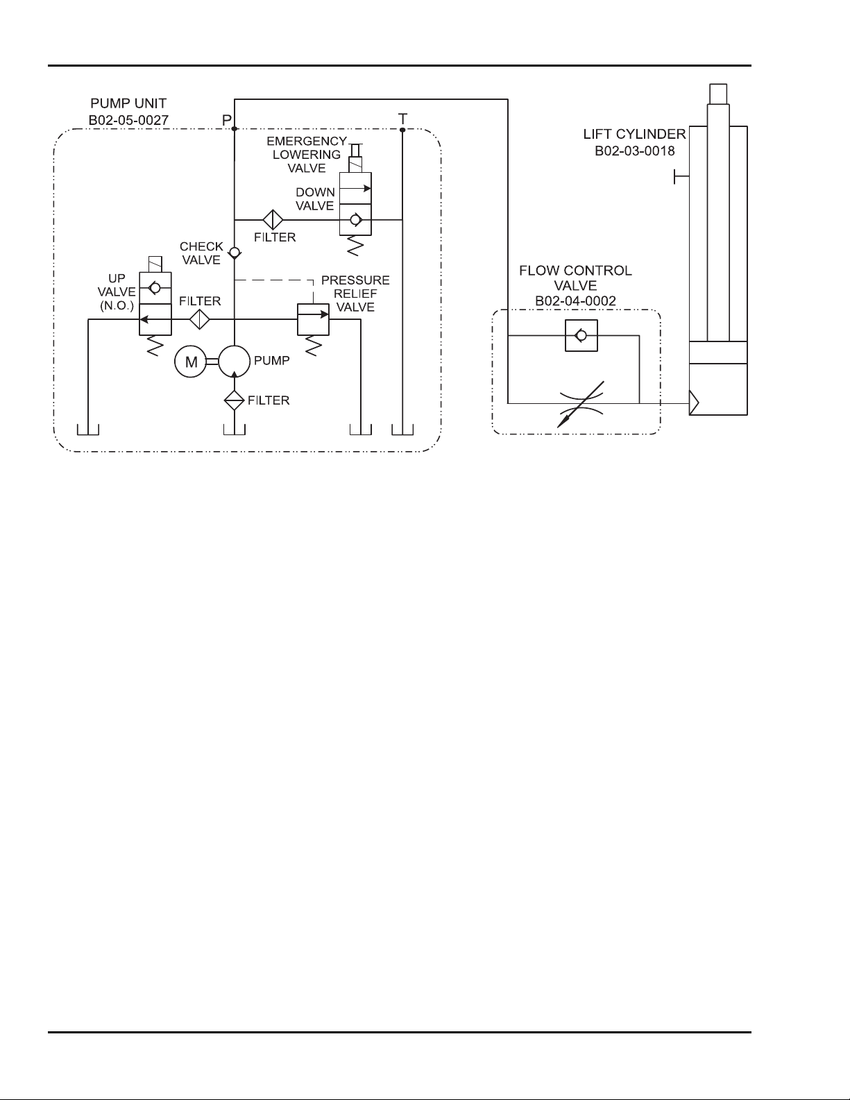
SkyRider 15
Figure 4-14. Hydraulic Diagram
4-20
Page 43
4 — MAINTENANCE
Figure 4-15. PC Logic Diagram
4-21
Page 44
SkyRider 15
FREE WHEEL
SWITCH NO
LOWER CONTROL BOX
E-
BRAKE
CAN P5V
CAN-HI
CAN-L0
Brake
+24V
IN 0
+24V
RXD
SOLENOID
R
1
G
2
B
3
4
W
1
2
2
3
1
4
CAN L
CAN H
CAN GND
CAN P5V
CAUTION
LIGHT
W
B
1
32
4
B
R B
W
EASI-0
W
1
32
4
B
EASI-24
MOTOR CONTROLLER
Motor
(-)
W
(+)
B
Motor
(+)
GND
CAN GND
TAD
UPNODN
B G
Mast Down
Lower Down
Lower Raise
GBWRGBWR
Upper Controls
IO Power-1
NO
W
R
IN-4
F1 2AMP
Pothole Down
Pothole Up
Steer Left
F2 10AMP
Steer Right
POS 24V
NEG 24V
2
2
1
1
G BWB
Down Valve +
IO Power A3
IO Power 4
IO Power 5
Hourmeter
Down
Horn
Up
BWB
W
Pump
Level
Sensor
W
Stop
NC
IN-5
IN-6
B
IN-7
Up
Low
Cntl
Cntl
NO
NO
MAST SWITCH
B
IO Power 2
NO
HOURMETER
+
B
W
_
POTHOLE
STEERING
B R
2
1
B
W
_
+
BEEPER
G RWB
NO
Valve
R
B
2
1
B
W
PUMP UNIT
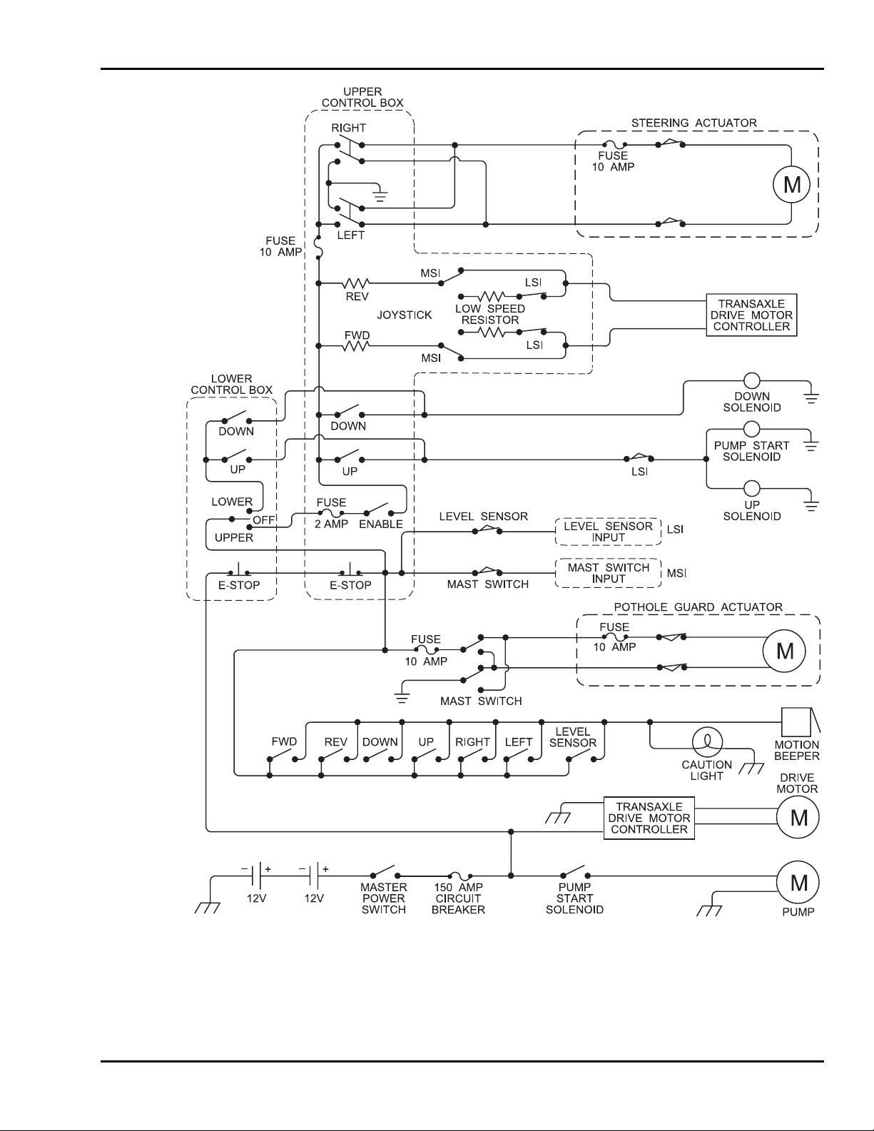
Figure 4-16. Lower Control Wiring Diagram
4-22
Page 45
4 — MAINTENANCE
_
BATTERY
+
MOTOR CONTROLLER
_
BATTERY
+
Motor
(-)
(+)
Motor
(+)
CAN P5V
CAN GND
CAN-HI
CAN-L0
Brake
+24V
IN 0
+24V
R
1
G
2
B
3
4
W
1
2
2
3
1
4
120”
18-4
TRANSAXLE
BRAKE
FREEWHEEL
SWITCH
1
C
NO
2
NC
BATTERY
GAUGE
MASTER
R
B
POWER
SWITCH
BAT
CIRCUIT
BREAKER
AUX
R
B
24 VOLT
BATTERY
CHARGER
Figure 4-17. Drive Wiring Diagram
110 VOLT
CHARGING
RECEPTACLE
PUMP UNIT
4-23
Page 46
SkyRider 15
E-STOP
GR GR
MAST
UP
GY
BK
GR
MAST
DOWN
PL
BK
GR
RD
GR
PL
BK
YL
BK
YL
ENABLE
GY
RD
RIGHT
TURN
BL
RD
STEERING
COM
NCN
O
RD
W
COM
NON
BL
W
RD GR
BK
C
LEFT
TURN
YL
GR
BK
1
4
YL
1
23
4
23
RD
Figure 4-18. Upper Control Wiring Diagram
4-24
Page 47

5
Replacement Decals
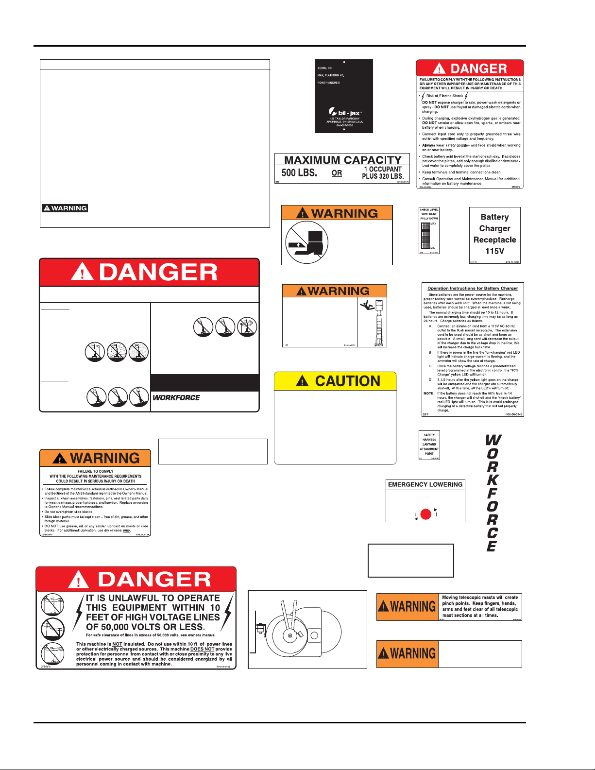
Refer to Table 5-1, and Figures 5-1, 5-2, and 5-3 for descriptions and locations of decals
on the SkyRider 15.
Table 5-1. Replacement Decals
Decal No. Description of Decal
B06-00-0009 Warning...Moving telescopic masts will create... 2
B06-00-0034 Danger...During charging, explosive oxyhydrogen gas... 1
B06-00-0137 Workforce (Vertical transfer type decal) 2
B06-00-0138 Warning...(Maintenance decal) 1
B06-00-0146 Danger...(High voltage line warning) 1
B06-00-0167 Striped Safety Tape - On all four sides (per roll only) 28 Ft.
B06-00-0170 Maximum Capacity...500 lb. Or... 3
B06-00-0173 Safety harness lanyard attachment point 2
B06-00-0192 Operation and service manual inside 1
B06-00-0225 Warning...Stay clear when raising or lowering 2
B06-00-0286 Emergency Lowering 1
B06-00-0289 Check level with cage fully down 1
B06-00-0296 Battery Charger Receptacle 1
B06-00-0385 Warning...Full Body Harness and Lanyard... 1
B06-00-0349 Operation Instructions for Battery Charger 1
B06-00-0359 Serial Number Tag (Not available as replacement part) 1
B06-00-0382 Caution...This machine designed and manufactured... 1
B06-00-0383 Danger...Failure To Comply With The Following... 1
B06-00-0384 Warning...Stand clear when raising or lowering lift. 2
B06-00-0386 Operation Instructions for SkyRider 15 2
B06-00-0387 SkyRider 15, Yellow (Transfer type decal) 2
B06-00-0388 SkyRider 15, Black (Transfer type decal) 1
B06-00-0390 Trans Axle Instruction 2
B06-00-0130 Lubricate Monthly 6
Qty
5-1
Page 48
SkyRider 15
OPERATION INSTRUCTIONS FOR SKYRIDER 15
1. Read and follow safety precautions and all responsibilities sections set forth in the operators manual
2. Make sure the lift is on a firm and level surface and that there are no potential hazards such as overhead
obstructions or electrically charged conductors, use the lift where such hazards exist.
3. Check the lift for damaged or worn parts and repair or replace as necessary.
4. Check to be sure that the cage is properly attached to the lift.
5. Turn master switch to on. Switch is located on the side of the lift.
6. Check to be sure all safety devices are functioning properly.
7. To operate lift from the ground turn and hold lower control switch to "lower control" setting then select either
up or down function.
8. To operate lift from the platform, turn lower control switch to "upper control" setting.
9. Enter platform and be certain that the entry gate is closed completely. If operating with entry gate open, operator
must wear full body harness and lanyard. Stand with back to the mast sections and face entry gate.
TORAISEORLOWER:
Depress and hold the "enable" button (this must be done prior to any other function being activated or reset of
•
the controls will be necessary).
Press either the raise or lower button.
•
TO DRIVE:
Depress and hold the "enable" button (this must be done prior to any other function being activated or reset of
•
the controls will be necessary).
Push joystick in the direction (forward or backward) that you wish to travel.
•
Press the steering thumb switch on the top of the joystick in the direction you wish the lift to turn (either right
•
or left).
The joystick and steering thumb switch may be operated simultaneously for smooth maneuvering.
•
DO NOT attempt to operate the drive function and the raise/lower function at the same time. The unit will
•
stop operating and reset of the controls will be necessary.
This lift is equipped with a level sensor that will prevent the lift from raising or driving with platform elevated
while on an unlevel surface. If the lift fails to raise or drive while elevated, lower platform immediately.
UOT
DO NOT
B06-00-0386
B06-00-0386
FAILURE TO COMPLY WITH THE FOLLOWING SAFETY INSTRUCTIONS OR ANY OTHER IMPROPER
USE OF THIS EQUIPMENT WILL RESULT IN SERIOUS INJURYOR DEATH.
BEFORE USE:
This equipment to be used by competent, fully trained, and authorized personnel only.
•
Operator must read and understand owner's manual and all decals before operating.
It is the operator's responsibility to comply with all warnings and instructions.
NEVER TAKE CHANCES - DO NOT operate this lift if you are under the influence of
•
drugs or alcohol, or if you fell dizzy, ill or unsteady in any way.
ALWAYSsurvey the job site and identify all potential hazards.
•
DO NOT override or alter any safety devices or make any modifications that would
•
affect the original design of the lift.
Inspect unit for damaged or worn
•
parts. DO NOT use until such
parts are replaced. DO NOT use
if lift is not working properly.
DO NOT use when exposed to
•
wind, rain, snow or ice.
Check all safety devices for
•
proper function prior to each use.
DO NOT use without entry gate in
•
the closed position unless operator is wearing a full body harness and lanyard and with
the lanyard attached to factory provided attachment point.
DURING USE:
DO NOT raise platform while on uneven, soft, or sloped surfaces.
•
DO NOT DRIVE lift onto uneven,
•
soft, or sloped surfaces while
elevated.
DO NOT climb up or down masts.
•
•
Work only within the platform guard rail area and do not attempt to increase working
height with boxes, ladders, scaffolding or any other means.
•
DONOT drivenear loading docks,
ditches, holes, unguarded openings,open elevatedshafts or
drop-offs.
•
DONOT usewhere lift cancome
into contact with overhead obstructions such as electrical
wires,cables, ropesor overor overhangs, etc..
•
DO NOT exert horizontal force to platform while performing work.
•
DO NOT move lift if you do not have a clear view of the path of travel.
•
DO NOT exceed manufacturer's recommended load capacity.
•
DONOTstandorsitonguardrails..
•
DO NOT lean out over guard rails to perform work.
•
DO NOT raise or lower lift until you are certain all personnel are clear.
•
DO NOT use near cranes or other moving vehicles.
•
DO NOT leave keys in machine while unattended.
•
DO NOT allow flames, sparks or embers near batteries and do not smoke near
batteries. Batteries produce highly flammable gases which can explode.
OWNERS & OPERATORS ARE RESPONSIBLE FOR INSPECTION, MAINTENANCE,
TRAINING, AND OPERATION AS REQUIRED BY THE OWNERS MANUAL AND THE
ANSI A92.6 STANDARD (IN EFFECT AT DATE OF MANUFACTURE).
AERIAL WORK PLATFORMS
IF YOU HAVE NOT BEEN PROVIDED WITH SAFETY
LITERATURE, OR FOR ANY QUESTIONS CONCERNING
THE SAFE USE OF THIS EQUIPMENT, CALL 419/445-9675.
B06-00-0383UOT
B06-00-0383
OPERATION AND SERVICE
MANUAL INSIDE
COFC B06-00-0192
B06-00-0192
SP-
12FT.
24V DC
PATENTPENDING
B06-00-0359
B06-00-0170
Stand clear when raising or
lowering lift.
Pot hole protection device
automatically lowers while lift is
being raised.
Contact with pot hole protection
device will cause serious crushing
UOT B06-00-0384
injury.
B06-00-0384
Full Body Harness and Lanyard
must be used whenever lift is
operated with entry gate open.
Failure to wear Full Body Harness
and Lanyard may allow operator
to fall from platform resulting in
serious injury or death.
B06-00-0385
This machine is designed and manufactured in
compliance with the ANSI A92.6 standard in force on
the date of manufacture. Dealers, owners, users,
operators, lessors, and lessees are responsible for
inspection, maintenance, training, and operation as
required by A92.6 and the owners manual.
Alterations, modifications, or changes to this
machine without the written authorization of bil-jax,
inc. as well as any unauthorized adjustment of valves,
disabling or by-passing of safety devices or the
improper use of this machine shall exempt bil-jax, inc.
from any liability for any resulting injuries or damage.
B06-00-0382UOT
B06-00-0382
B06-00-0034
B06-00-0289
B06-00-0296
B06-00-0349
B06-00-0173
TURN RED KNOB COUNTER
SR 15KY IDER
B06-00-0387
CLOCKWISE TO LOWER
CCFA
B06-00-0286
B06-00-0286
SR 15
B06-00-0138
KY IDER
B06-00-0388
LUBRICATE
MONTHLY
RIF
B06-00-0137
B06-00-0130
B06-00-0130
Normal Drive
B06-00-0146
FreeWheel
B06-00-0390
Transaxle
B06-00-0009
STAY CLEAR
WHILE RAISING
OR LOWERING
CCFO
B06-00-0225
B06-00-0225
Figure 5-1. Replacement Decals
5-2
Page 49
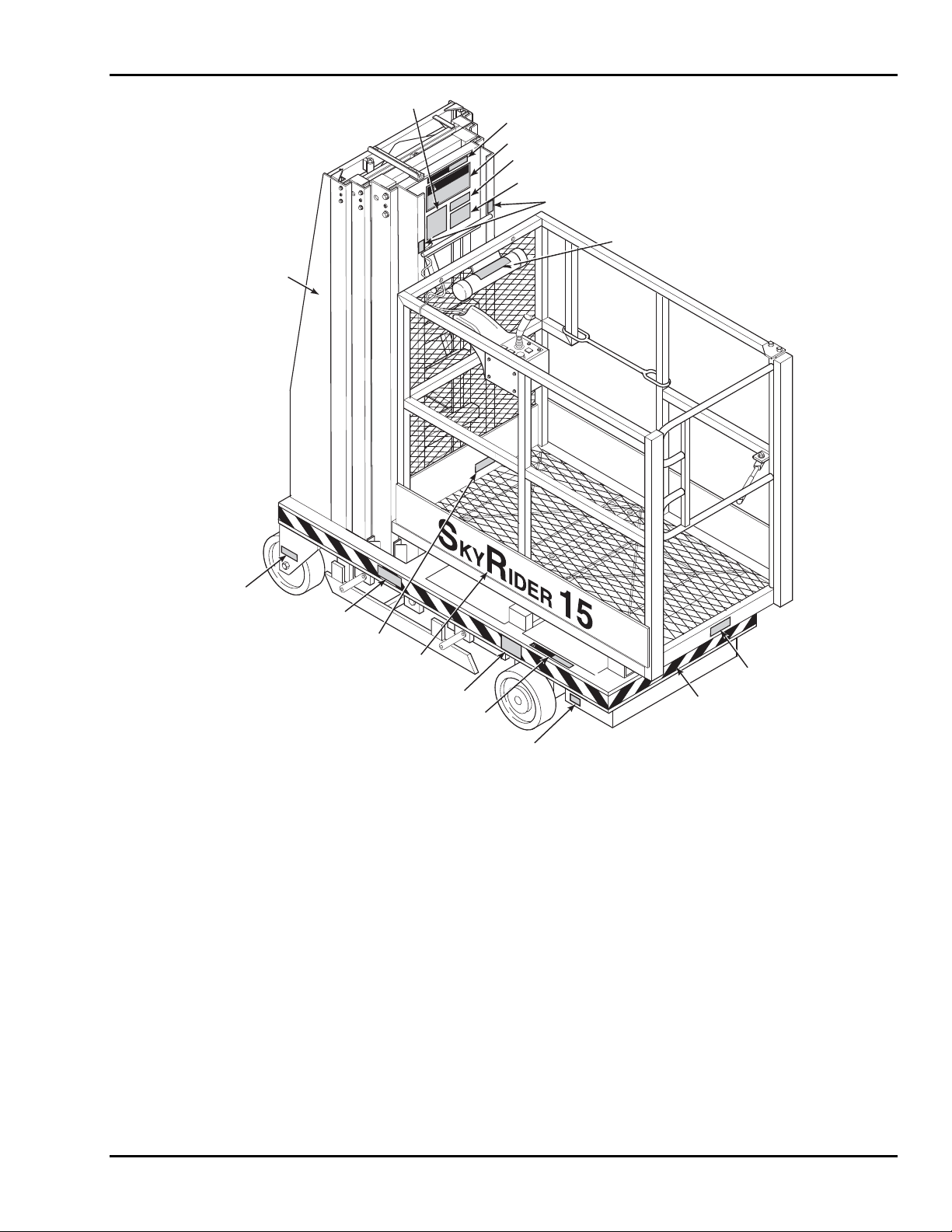
5 — REPLACEMENT DECALS
0386
0009
0146
0170
WARNING
DANGER
0385
0173
0130
0137
W
O
R
K
F
O
R
C
E
0384
0170
0387
0390
0225
0130
WARNING
0192
0167
AROUND COMPLETE
( )
BASE ON ALL SIDES
0170
Figure 5-2. Decal Locations, Side View
5-3
Page 50
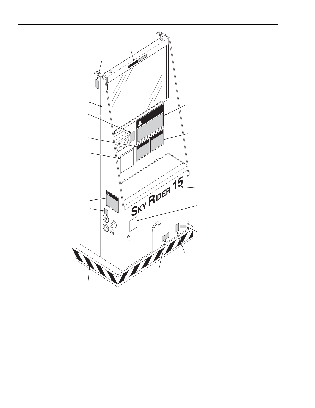
SkyRider 15
0009
0359
WARNING
0137
0390
0138
0386
0034
0296
W
O
R
K
O
R
C
E
F
DANGER
DANGER
CAUTION
WARNING
0383
0382
0388
0349
INSIDE
)
(
DOOR
0130
ON STEERING
(
PIVOT BLOCK
)
0289
ON RESERVOIR
(
INSIDE
0286
0167
AROUND COMPLETE
(
BASE ON ALL SIDES
5-4
)
Figure 5-3. Decal Locations, Rear View
)
Page 51

6
Parts List
6-1
Page 52
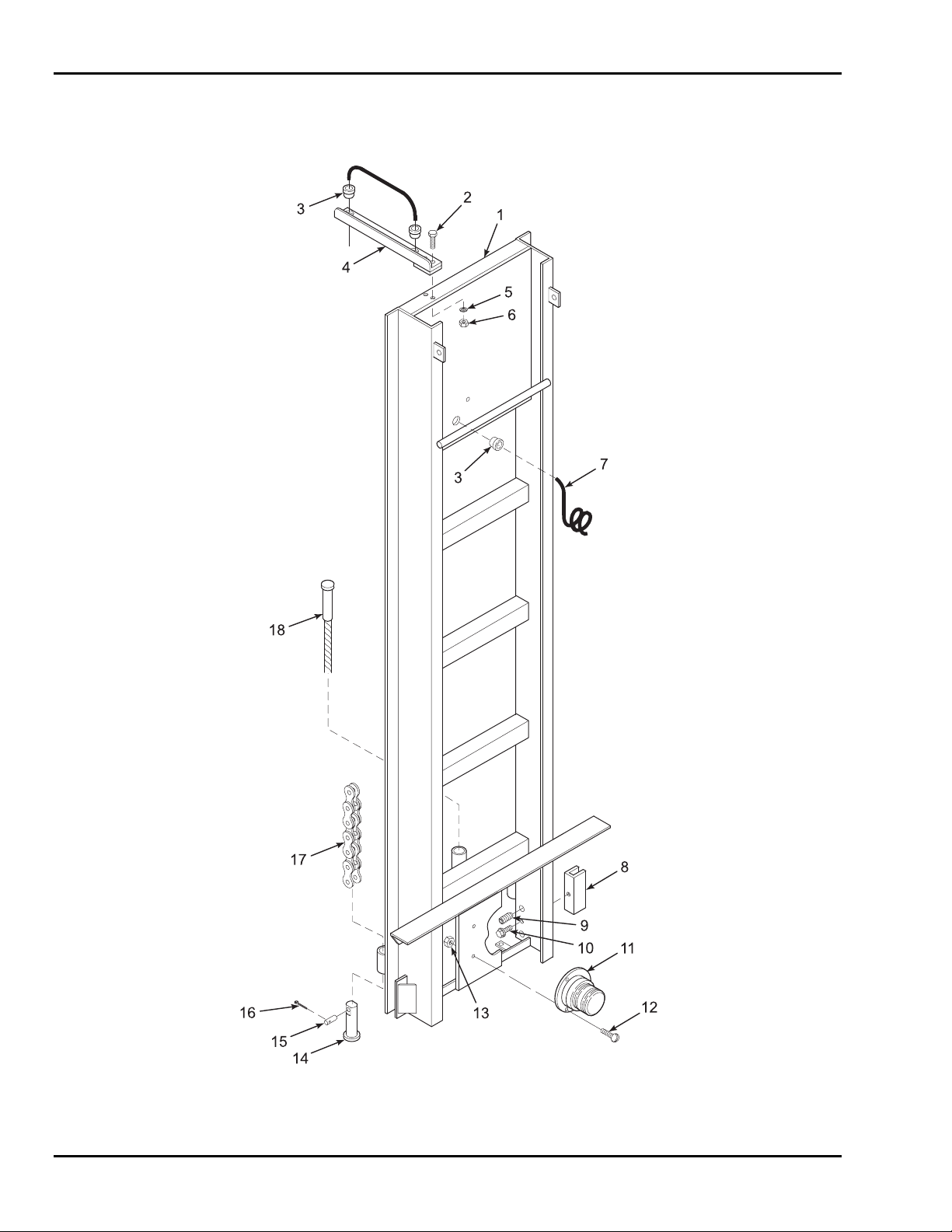
SkyRider 15
6-1 TOP MAST PARTS LIST
Refer to Table 6-1 for the parts list for the top mast.
Figure 6-1. Top Mast
6-2
Page 53

6 — PARTS LIST
Table 6-1. Top Mast Parts List
Item No. Part No. Description Qty
1 B16-01-0038 Top Mast Weldment 1
2 0090-0014 Screw, Cap, 1/4-20 x 2-1/4 in. 2
3 B01-09-0026 Grommet, Plastic 3
4 B29-00-0076 Bracket, Outreach 1
5 0090-0206 Washer, Lock, Split, 1/4 in. 2
6 0090-0159 Nut, Hex, 1/4-20 2
7 B01-01-0128 Cable, Coiled, 18-2 1
8 B31-00-0001 Slide Block, Plastic 2
9 0090-0389 Screw, Set, 1/2-20 x 1/2 in. 4
10 0090-0403 Screw, Sheet Metal, #10 x 1 in. 2
11 B01-10-0004 Light, Caution 1
12 0090-0802 Screw, Machine, #10-24 x 7/8 in. 3
13 0090-0182 Nut, Hex, Nylon Lock, #10-24 3
14 B04-07-0087 Clevis, Lower 2
15 B04-07-0078 Pin, Clevis 2
16 0090-0860 Pin, Cotter 2
17 B40-01-0008 Chain, Lift 2
18 B40-00-0003 Cable, Steel, 3/16 in. 1
* B03-00-0009 Chain Assy, includes items 14, 15, 16, and 17 1
*NOTE: It is recommended that chain parts be purchased as an assembly.
6-3
Page 54
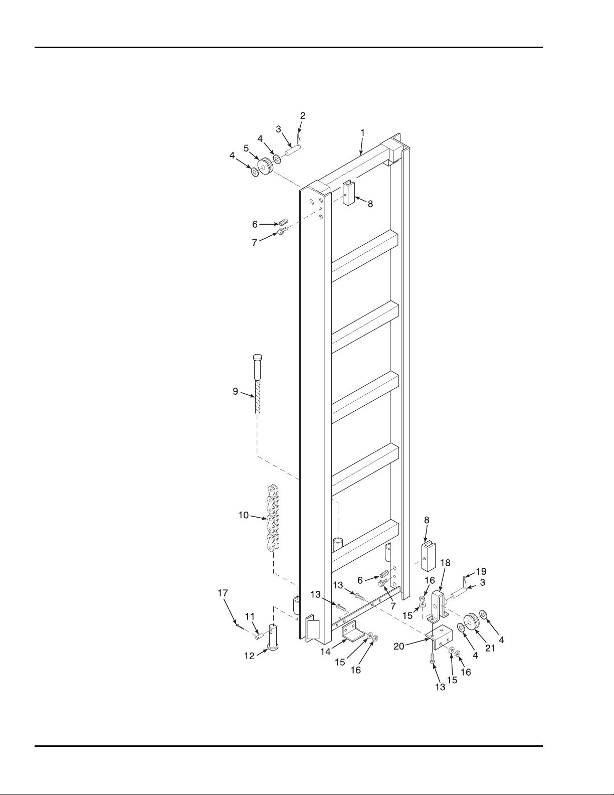
SkyRider 15
6-2 CENTER MAST PARTS LIST
Refer to Table 6-2 for the parts list for the center mast.
Figure 6-2. Center Mast
6-4
Page 55

6 — PARTS LIST
Table 6-2. Center Mast Parts List
Item No. Part No. Description Qty
1 B16-01-0020 Center Mast Weldment 1
2 0090-0770 Pin, Cotter, 3/16 x 1-1/2 in. 2
3 B36-01-0002 Axle, Sheave 3
4 0090-0425 Washer, Flat, 5/8 in. 6
5 B26-00-0009 Sheave Assembly, Chain 2
6 0090-0389 Screw, Set, 1/2-20 x 1/2 in. 8
7 0090-0403 Screw, Sheet Metal, #10 x 1 in. 4
8 B31-00-0001 Slide Block, Plastic 4
9 B40-00-0003 Cable, Steel, 3/16 in. 1
10 B40-01-0008 Chain, Lift 2
11 B04-07-0078 Pin, Clevis 2
12 B04-07-0087 Clevis, Lower 2
13 0090-0042 Screw, Cap, 3/8-16 x 1 in. 6
14 B29-00-0033 Mast Stop 1
15 0090-0210 Washer, Lock, Split, 3/8 in. 6
16 0090-0162 Nut, Hex, 3/8-16 6
17 0090-0860 Pin, Cotter 1
18 B29-00-0078 Bracket, Weldment 1
19 0090-0147 Pin, Cotter, 1/8 x 1-1/4 in. 1
20 B24-01-0008 Mounting Bracket 1
21 B26-00-0001 Sheave, Cable 1
* B03-00-0009 Chain Assy, includes items 10, 11, 12, and 17 1
*NOTE: It is recommended that chain parts be purchased as an assembly.
6-5
Page 56
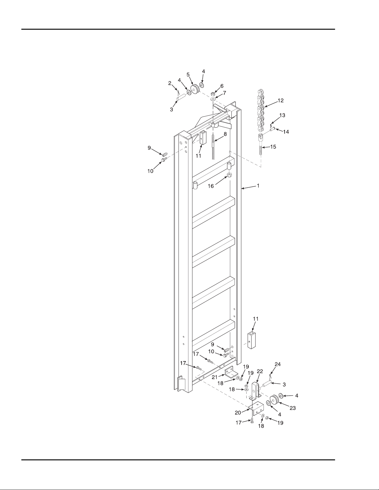
SkyRider 15
6-3 LOWER MAST PARTS LIST
Refer to Table 6-3 for the parts list for the lower mast.
Figure 6-3. Lower Mast
6-6
Page 57

6 — PARTS LIST
Table 6-3. Lower Mast Parts List
Item No. Part No. Description Qty
1 B16-01-0021 Lower Mast Weldment 1
2 0090-0770 Pin, Cotter 3/16 x 1-1/2 in. 2
3 B36-01-0002 Axle, Sheave 3
4 0090-0425 Washer, Flat, 5/8 in. 6
5 B26-00-0009 Sheave Assembly, Chain 2
6 0090-0188 Nut, Hex, Nylon Lock, 3/8-16 1
7 0090-0422 Washer, Flat, 3/8 in. 1
8 B40-00-0003 Cable, Steel, 3/16 in. 1
9 0090-0389 Screw, Set, 1/2-20 x 1/2 in. 8
10 0090-0403 Screw, Sheet Metal, #10 x 1 4
11 B31-00-0001 Slide Block, Plastic 4
12 B40-01-0008 Chain, Lift 2
13 0090-0860 Pin, Cotter 2
14 B04-07-0078 Pin, Clevis 2
15 B04-07-0088 Clevis, Upper 2
16 0090-0192 Nut, Hex, Nylon Lock, 1/2-13 2
17 0090-0042 Screw, Cap, 3/8-16 x 1 in. 6
18 0090-0210 Washer, Lock, Split, 3/8 in. 6
19 0090-0162 Nut, Hex, 3/8-16 6
20 B24-01-0008 Mounting Bracket 1
21 B29-00-0033 Mast Stop 1
22 B29-00-0078 Bracket, Weldment 1
23 B26-00-0001 Sheave, Cable 1
24 0090-0147 Pin, Cotter 1
* B03-00-0009 Chain Assy, includes items 12, 13, 14, and 15 1
*NOTE: It is recommended that chain parts be purchased as an assembly.
6-7
Page 58
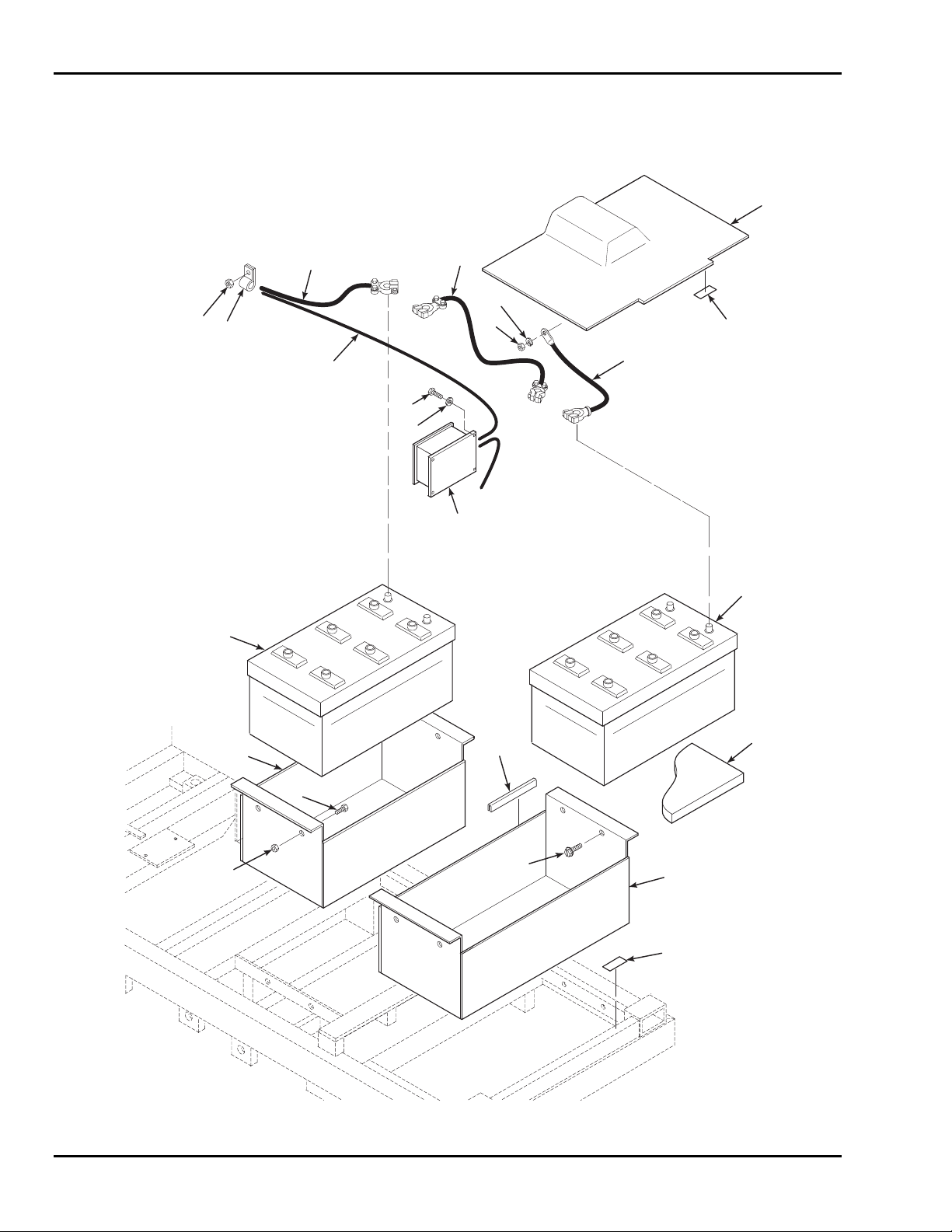
SkyRider 15
6-4 BATTERY COMPARTMENT PARTS LIST
Refer to Table 6-4 for the parts list for the battery compartment.
1
15
14
3
16
13
21
11
17
12
18
19
2A
20
3
10
8
9
7
6
5
2B
4
Figure 6-4. Battery Compartment
6-8
Page 59

6 — PARTS LIST
Table 6-4. Battery Compartment Parts List
Item No. Part No. Description Qty
1 B18-00-0146 Cover, Battery Compartment 2
2A B05-04-0007 Velcro, 400 Stem 24 in.
2B B05-04-0008 Velcro, 170 Stem 24 in.
3 B01-04-0008 Battery, 12 Volt, 8D, 200 Amp-Hour 2
4 B00-00-0128 Mat, Battery, 11 x 20 x 1/8 in. 2
5 B11-01-0104 Tray, Battery, Front 1
6 0090-0934 Screw, Threadcutting, 1/4-20 x 3/4 in. 6
7 B34-00-0006 Trimlock, 1/8 x 6 in. 3
8 0090-0688 Screw, Cap, 1/4-20 x 1 in. 2
9 0090-0183 Nut, Hex, Nylon Lock, 1/4-20 2
10 B11-01-0103 Tray, Battery, Rear 1
11 0090-0946 Washer, Lock, 3/8 in. Stainless Steel 2
12 B01-10-0196 Controller, Motor 1
13 B01-01-0130 Cable, 4 Ga. x 72 in. 1
14 B04-07-0034 Clamp, Cable/Hose, DG 12 1
15 0090-0183 Nut, Hex, Nylon Lock, 1/4-20 1
16 B01-01-0132 Cable, Battery, 2 Ga. x 60 in. 1
17 B01-01-0133 Cable, Battery, 2 Ga. x 22 in. 1
18 0090-0162 Nut, Hex, 3/8-16 1
19 0090-0210 Washer, Lock, Split, 3/8 in. 1
20 B01-01-0006 Cable, Battery, 2 Ga. x 16 in. 1
21 0090-0945 Screw, Cap, 3/-16 x 3/4 in., Stainless Steel 2
6-9
Page 60
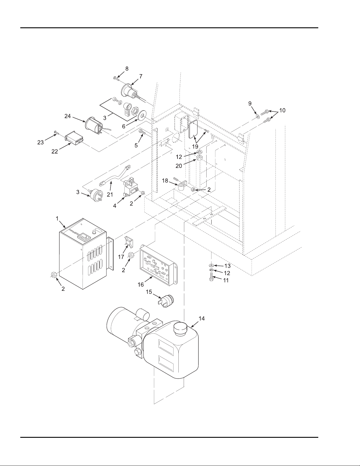
SkyRider 15
6-5 HYDRAULIC PUMP COMPARTMENT PARTS LIST
Refer to Table 6-5 for the parts list for the hydraulic pump compartment.
Figure 6-5. Hydraulic Pump Compartment
6-10
Page 61

6 — PARTS LIST
Table 6-5. Hydraulic Pump Compartment Parts List
Item No. Part No. Description Qty
1 B01-05-0006 Charger, Battery, 40 Amp, 110 Volt AC, 60 1
2 0090-0183 Nut, Hex, Nylon Lock, 1/4-20 11
3 B01-02-0060 Switch, Master Power 1
4 B01-10-0141 Circuit Breaker, 150 Ampere 1
5 0090-0688 Screw, Cap, 1/4-20 x 1 in. 2
6 B00-00-0112 Faceplate, Master Power Switch 1
7 B01-10-0003 Receptacle, Flush Mount 1
8 0090-0344 Screw, Sheet Metal, #10-24 x 1/2 in. 2
9 0090-0419 Washer, Flat, 1/4 in. 4
10 0090-0005 Screw, Cap, 1/4-20 x 3/4 in. 8
11 0090-0040 Screw, Cap, 3/8-16 x 3/4 in. 2
12 0090-0210 Washer, Lock, Split, 3/8 in. 3
13 0090-0422 Washer, Flat, 3/8 in. 2
14 B02-05-0027 Pump, Hydraulic 1
15 B01-10-0002 Alarm, Audible 1
16 B01-10-0195 Control Board, Main 1
17 B04-07-0015 Clamp, Tie Wrap 3
18 B04-07-0034 Clamp, Cable/Hose, DG 12 1
19 B18-00-0026 Cover, Receptacle Box (with screws) 1
20 0090-0162 Nut, Hex, 3/8-16 1
21 B01-01-0014 Cable, Battery, 2 Ga. x 8 in. 1
22 B01-10-0007 Hour Meter 1
23 0090-0627 Screw, #4-40 x 1/2 in. 2
24 B01-10-0017 Battery Gauge 1
6-11
Page 62
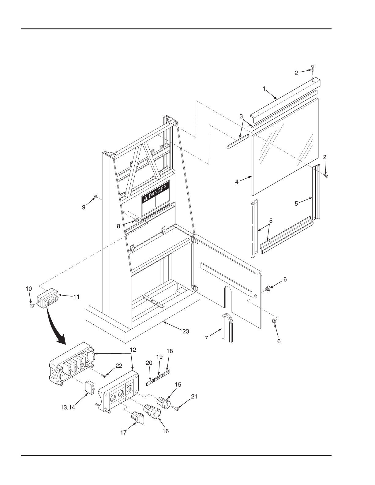
SkyRider 15
6-6 BASE PARTS LIST
Refer to Table 6-6 for the parts list for the base.
Figure 6-6. Base
6-12
Page 63

6 — PARTS LIST
Table 6-6. Base Parts List
Item No. Part No. Description Qty
1 B07-01-2003 Edge, Top Cover 1
2 0090-0344 Screw, Sheet Metal, #10-24 x 1/2 in. 8
3 B05-00-0006 Tape, Foam Adhesive 32 in.
4 B18-00-0108 Plexiglass, 1/8 in. 1
5 B24-01-0009 Frame, Aluminum 3
6 B37-00-0006 Lock Assembly, Utility 1
7 B34-00-0005 Trimlock, 3/32 in. 17 in.
8 B01-09-0026 Grommet, Plastic 1
9 0090-0181 Nut, Hex, Nylon Lock, #8-32 2
10 B01-09-0003 Strain Relief, Cable 1
11 B01-02-0076 Control Box Assembly, Lower 1
12 B19-00-0040 Box, Switch, 3 Position 1
13 B01-02-0078 Contacts, Switch, Normally Open 4
14 B01-02-0079 Contacts, Switch, Normally Closed 1
15 B01-02-0082 Switch, Selector, Keyed 1
16 B01-02-0081 Switch, Pushbutton, Emergency Stop 1
17 B01-02-0080 Switch, Selector, Up/Down 1
18 B00-00-0131 Legend Plate, Upper/Off/Lower 1
19 B00-00-0130 Legend Plate, Emergency Stop 1
20 B00-00-0129 Legend Plate, Up/Down 1
21 B38-00-0001 Key, Replacement 1
22 0090-0798 Screw, Machine, #8-32 x 3/4 in. 2
23 B11-01-0106 Weldment, Base and Mast 1
6-13
Page 64
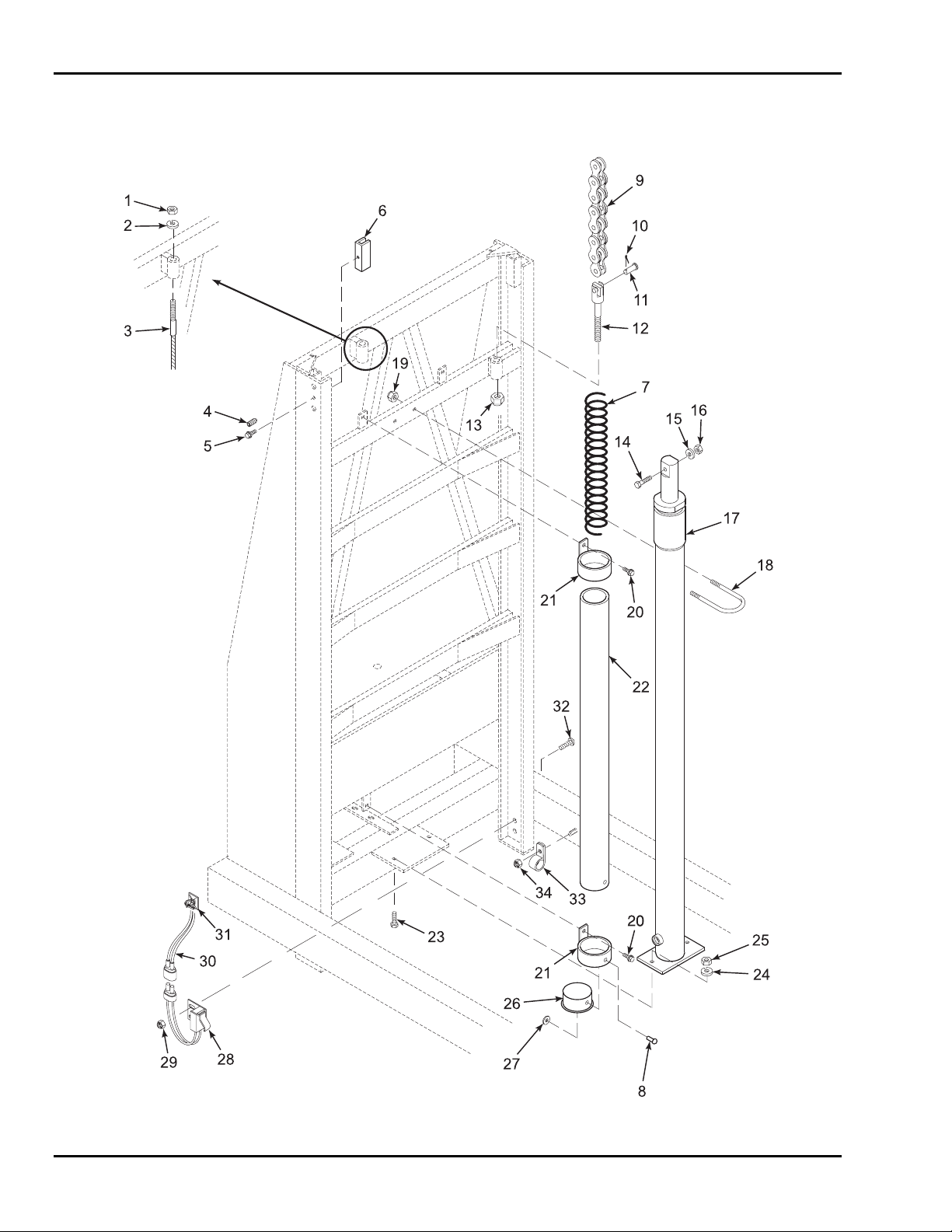
SkyRider 15
6-7 BASE MAST PARTS LIST
Refer to Table 6-7 for the parts list for the base mast.
Figure 6-7. Base Mast
6-14
Page 65

6 — PARTS LIST
Table 6-7. Base Mast Parts List
Item No. Part No. Description Qty
1 0090-0188 Nut, Hex, Nylon Lock, 3/8-16 1
2 0090-0422 Washer, Flat, 3/8 in. 1
3 B40-00-0003 Cable, Steel, 3/16 in. 1
4 0090-0389 Screw, Set, 1/2-20 x 1/2 in. 4
5 0090-0403 Screw, Sheet Metal, #10-24 x 1 in. 2
6 B31-00-0001 Slide Block, Plastic 2
7 B01-01-0128 Cord, Coiled, 18-2 1
8 0090-0684 Rivet, Pop, 3/16 x 1/2 in. 2
9 B40-01-0008 Chain, Lift 2
10 0090-0860 Pin, Cotter, 1.6 mm 2
11 B04-07-0078 Pin, Clevis 2
12 B04-07-0088 Clevis, Upper 2
13 0090-0192 Nut, Hex, Nylon Lock, 1/2-13 2
14 0090-0071 Screw, Cap, 1/2-13 x 2-1/2 in. 1
15 0090-0212 Washer, Lock, Split, 1/2 in. 1
16 0090-0166 Nut, Hex, 1/2-13 1
17 B02-03-0018 Cylinder, Hydraulic Lift, 1.5 in. diameter 1
18 0090-0654 Clamp, U-bolt, 5/16-18 x 2-1/2 x 2-5/8 1
19 0090-0185 Nut, Hex, Nylon Lock, 5/16-18 2
20 0090-0344 Screw, Thread Cutting, #10-24 x 1/2 2
21 B29-00-0049 Retainer, Tube 2
22 B00-00-0007 Tube, Plastic 1
23 0090-0043 Screw, Cap, 3/8-16 x 1-1/4 2
24 0090-0210 Washer, Lock, Split, 3/8 in. 2
25 0090-0162 Nut, Hex, 3/8-16 2
26 B00-00-0008 Plug, Plastic 1
27 0090-0498 Washer, Flat, 3/16 in. 2
28 B01-03-0040 Switch, Limit, Mast 1
29 0090-0182 Nut, Hex, Nylon Lock, #10-24 2
30 B01-01-0129 Cable Assembly, Mast Limit Switch 1
31 B04-07-0015 Clamp, Cable 2
32 0090-0231 Screw, Machine, #10-24 x 1/2 2
33 B04-07-0034 Clamp, Cable/Hose, DG 12 1
34 0090-0183 Nut, Hex, Nylon Lock, 1/4-20 1
* B03-00-0009 Chain Assy, includes items 9, 10, 11, and 12 1
*NOTE: It is recommended that chain parts be purchased as an assembly.
6-15
Page 66
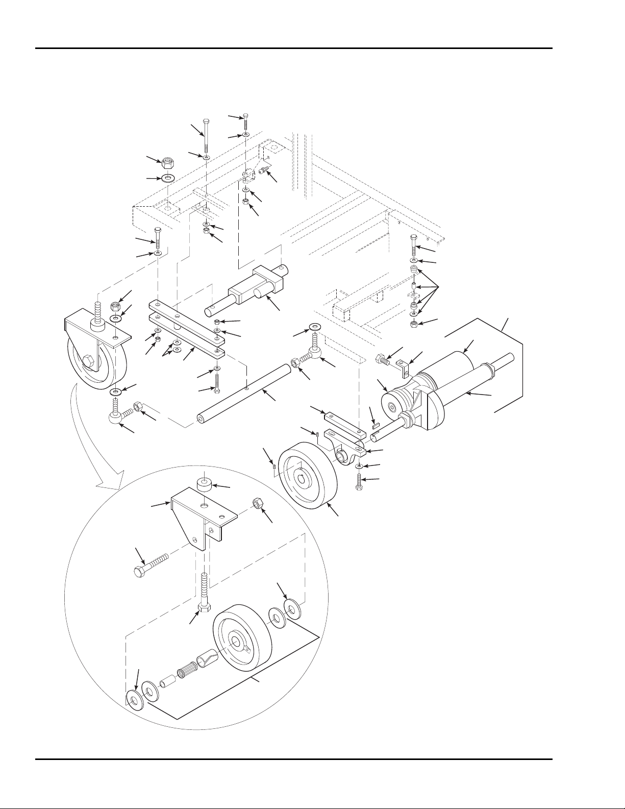
SkyRider 15
6-8 DRIVE AXLE AND STEERING PARTS LIST
Refer to Table 6-8 for the parts list for the drive axle and steering components.
10
31
18
34
27
26
31
32
26
38
30
39
31
36
31
37
38
32
33
23
26
15
24
25
7C
8
1
2
3
4
5
6
7B
7
7A
2
4
35
2
2
29
20
28
21
16
27
19
17
13
22
18
21
14
9
2
11
12
Figure 6-8. Drive Axle and Steering
6-16
Page 67

6 — PARTS LIST
N
y
k
r
r
t
N
g
N
N
g
N
r
N
Table 6-8. Drive Axle and Steering Parts List
Item No. Part No. Description Qty
1 0090-0049 Screw, Cap, 3/8-16 x 2-1/4 in. 1
2 0090-0422 Washer, Flat, 3/8 in. 7
3 B30-00-0050 Pad Assembly, Torsion 1
4 0090-0188
ut, Hex, Nylon Lock, 3/8-16 2
5 0090-0065 Screw, Cap, 1/2-13 x 1 in. 1
6 B07-01-1090 Bracket, Torsion 1
7 B01-07-0010 Transaxle Assembl
1
7A B01-07-0012 Transaxle Subassembly 1
7B B01-07-0011 Motor Subassembly 1
7C B01-07-0013 Brake Subassembly, Electric 1
8 B07-07-5022 Key, Square, 1/4 x 2-1/2 in. 2
9 B25-00-0073 Pillow Bloc
2
10 0090-0012 Screw, Cap, 1/4-20 x 2 in. 2
11 0090-0046 Screw, Cap, 3/8-16 x 1-3/4 in. 4
12 B08-02-0010 Caster, Drive 2
13 0090-0369 Screw, Set, 5/16-18 x 5/8 in. 4
14 0090-0367 Screw, Set, 1/4-28 x 1/4 in. 4
15 B30-00-0049 Mount, Rubbe
16 B11-01-0105 Weldment, Caste
17 B25-00-0011 Bearing, Thrus
18 0090-0195
ut, Hex, Nylon Lock, 3/4-10 4
2
2
2
19 0090-0861 Bolt, Steering Pivot, 3/4-10 x 4-1/2 2
20 0090-0112 Bolt, Steering Axle, 3/4-10 x 5 in. 2
21 0090-0429 Washer, Flat, 1 in. 4
22 B08-02-0011 Caster, Steerin
2
23 B07-10-1137 Tie Rod 4
24 0090-0846
ut, Hex, Jam, Left Hand Thread, 1/2-28 1
25 B25-00-0071 Tie Rod End, Left Hand 1
26 0090-0574 Washer, Flat, 1/2 in. 4
27 0090-0847
ut, Hex, Jam, 1/2-28 3
28 B25-00-0072 Tie Rod End, Right Hand 1
29 B11-01-0100 Linkage, Steerin
1
30 0090-0034 Screw, Cap, 5/16-18 x 2 in. 1
31 0090-0419 Washer, Flat, 1/4 in. 4
32 0090-0183
33 B01-10-0189 Actuator, Linea
ut, Hex, Nylon Lock, 1/4-20 2
1
34 0090-0428 Washer, Flat, 3/4 in. 2
35 0090-0613 Bolt, 3/8-16 x 4-1/2 in. 1
36 B00-00-0009 Fitting, Zerk, Drive-In 2
37 0090-0185
ut, Lock, 5/16 in. 1
38 0090-0420 Washer. Flat, 5/16 2
6-17
Page 68
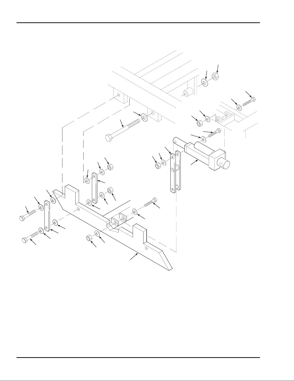
SkyRider 15
6-9 POTHOLE GUARD PARTS LIST
Refer to Table 6-9 for the parts list for the pothole guard components.
3
2
4
5
13
2
1
15
5
14
9
9
11
12
14
9
9
9
9
9
9
12
9
13
6
8
9
5
6
4
5
7
10
Figure 6-9. Pothole Guard
6-18
Page 69

6 — PARTS LIST
Table 6-9. Pothole Guard Parts List
Item No. Part No. Description Qty
1 0090-0088 Bolt, 1/2-13 x 9 in. 1
2 0090-0574 Washer, Flat, 1/2 in. 2
3 0090-0192 Nut, Hex, Nylon Lock, 1/2-13 1
4 0090-0012 Screw, Cap, 1/4-20 x 2 in. 2
5 0090-0419 Washer, Flat, 1/4 in. 4
6 0090-0183 Nut, Hex, Nylon Lock, 1/4-20 2
7 B01-10-0189 Actuator, Linear 1
8 0090-0051 Screw, Cap, 3/8-16 x 2-3/4 in. 1
9 0090-0422 Washer, Flat, 3/8 in. 34
10 B11-01-0102 Weldment, Pothole Guard 1
11 0090-0188 Nut, Hex, Nylon Lock, 3/8-16 1
12 B07-06-5520 Strap, Mounting 8
13 0090-0049 Screw, Cap, 3/8-16 x 2-1/4 in. 8
14 0090-0623 Nut, Jam, Nylon Lock, 3/8-16 8
15 B11-01-0101 Weldment, Linkage, Pothole Guard 1
6-19
Page 70
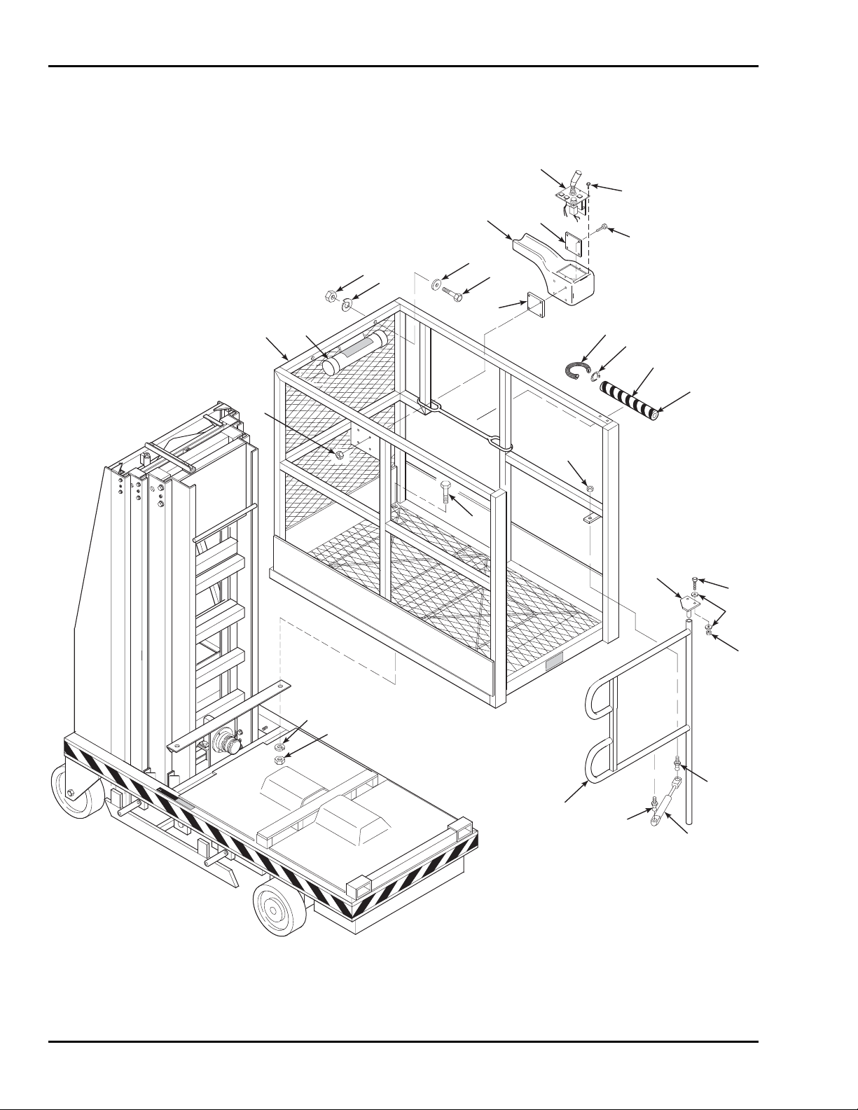
SkyRider 15
6-10 PLATFORM PARTS LIST
Refer to Table 6-10 for the parts list for the platform.
24
8
7
5
5
5
22
3
4
2
1
9
S
S
K
K
Y
Y
R
R
I
I
D
D
E
E
R
R
1
1
10
11
6
23
12
13
14
15
16
21
6
5
17
4
3
WARNING
20
18
Figure 6-10. Platform
6-20
18
19
Page 71

6 — PARTS LIST
Table 6-10. Platform Parts List
Item No. Part No. Description Qty
1 B17-00-0117 Weldment, Platform 1
2 B00-00-0014 Cap, Document Tube 2
3 0090-0162 Nut, Hex, 3/8-16 4
4 0090-0210 Washer, Lock, 3/8 in. 4
5 0090-0422 Washer, Flat, 3/8 in. 6
6 0090-0048 Screw, Cap, 3/8-16 x 2 in. 4
7 B18-00-0144 Control Box, Upper Enclosure 1
8 0090-0224 Screw, Machine, #8-32 x 3/8 in. 6
9 0090-0183 Nut, Hex, Nylon Lock, 1/4-20 4
10 B07-06-5548 Plate, Stress Relief 1
11 0090-0007 Screw, Cap, 1/4-20 x1-1/4 in. 4
12 B00-00-0086 Casing, Wire, Slit, 5/16 in. dia. x 8-1/2 in. long 2
13 B01-09-0030 Tyrap 6
14 B06-00-0167 Caution Tape, Black and Yellow 1 Roll
15 B05-00-0001 Tube, Foam 18 in.
16 0090-0160 Nut, Hex, 5/16-18 1
17 0090-0188 Nut, Hex, Nylon Lock, 3/8-16 2
18 0090-0920 Ball, Swivel 2
19 B39-00-0034 Gas Shock, Gate 1
20 B17-00-0106 Gate 1
21 B17-00-0108 Pin, Gate 1
22 0090-0051 Screw, Cap, 3/8-16 x 2-3/4 in. 2
23 B07-06-5549 Plate, Threaded, Control Box 1
24 B01-10-0197 Joystick Switch Plate Assembly,
1
Includes Circuit Board
6-21
Page 72
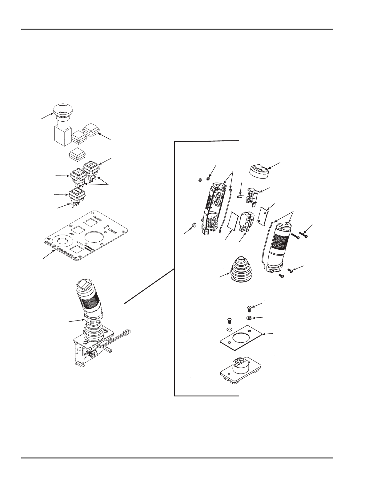
SkyRider 15
6-11 UPPER CONTROL BOX PARTS LIST
Refer to Table 6-11 for the parts list for the upper control box.
2
3
4,7
11
12
5,7
8
6,7
8
25
16
9
23,24
10
14
17
13
15
16
12
18
19
20
21
22
Figure 6-11. Upper Control Box
6-22
Page 73

6 — PARTS LIST
Table 6-11. Upper Control Box Parts List
Item No. Part No. Description Qty
B01-10-0197 Joystick Assembly 1
1 B01-10-0198 Circuit Board, Joystick (Not Shown) 1
2 B01-10-0201 Stop Switch, Emergency 1
3 B01-10-0205 Protection Skin, Push Button 3
4 B01-10-0202 Push Button, Arrow Up 1
5 B01-10-0203 Push Button, Arrow Down 1
6 B01-10-0204 Push Button, Enable 1
7 B01-10-0207 Mini Lamp, 6.3 volt 3
8 B01-10-0206 Switch, Cherry, Water/Dust Proof 3
9 B01-10-0200 Plate, Top Control 1
10 B01-10-0199 Joystick 1
11 0090-0525 Locknut, #4-40 2
12 B01-10-0216 Handle, Joystick, L & R Halves 1
13 B01-10-0214 Rubber Cup, Thumb Switch 1
14 B01-10-0212 Pin, Dowel 1
15 B01-10-0213 Switch, Thumb Actuator 1
16 B01-10-0215 Bracket, Switch Mounting 2
17 B01-10-0211 Switch, Double, Steering 1
18 0090-0500 Screw, Machine, #4-40 x 3/4 in. 2
19 B01-10-0217 Screw, Machine, Torx, #6-32 x 3/8 in. 2
20 0090-0243 Screw, Machine, #10-32 x 1/2 in. 2
21 B01-10-0209 Washer, Plastic 2
22 B01-10-0208 Gasket, Foam 1
23 B01-10-0210 Boot, Rubber 1
24 B01-10-0218 Clamp 1
25 0090-0180 Locknut, #6-32 2
6-23
Page 74
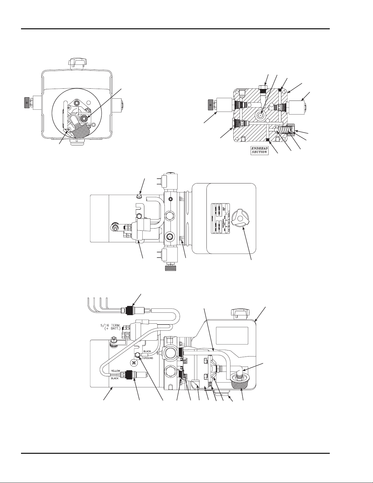
SkyRider 15
6-12 HYDRAULIC UNIT PARTS LIST
3
2
24
21
11
6, 13
31
27, 18
12
24
4
18, 28
23
29
17
9, 19
14
25
5
20 71022
11
33
32
30
31
Figure 6-12. Hydraulic Unit Assembly
34
16
15
26
8
6-24
Page 75

6 — PARTS LIST
Table 6-12. Hydraulic Unit Parts List
Item No. Part No. Description Qty
1 B02-15-0088 Bolt, Torx, 5/16-24 x 2-3/4 in. 2
2 B02-15-0119 Coupler, 9T-20-40 1
3 B02-02-0087 Plug, Drain, 9/16 SAE 1
4 B02-15-0128 Ball, Steel 1
5 B02-15-0091 Seal, Shaft 1
6 B02-15-0093 Washer 1
7 B02-15-0061 Magnet, Plumbing 1
8 B02-15-0121 Filter 1
9 B02-15-0386 Motor, DC, 24V 1
10 B02-15-0125 Cover, Suction 1
11 B02-15-0126 Screw, Taptite, M6 x 1.0, 12 mm Torx 2
12 B02-15-0197 Valve, Check, Cartridge 1
13 B02-15-0170 Bolt, 5/16-18 x 1 in. 1
14 B02-15-0199 Bolt, Hex, #12-24 x 1/2 in. 4
15 B02-15-0206 Tank, Horizontal Mount, Plastic with Drain 1
16 B02-15-0201 Breather Cap, with Check Valve 1
17 B02-15-0127 Spring, Relief 1
18 B02-15-0388 Coil, Solenoid, 24VDC 2
19 B02-15-0114 Pin, 1/8 x 1/4 1
20 B02-15-0073 O-Ring 1
21 B02-15-0203 Head, End 1
22 B02-15-0078 Pump Assembly, 1.6 GPM 1
23 B02-15-0030 Cap Assembly, Relief 1
24 B02-15-0204 Plug, 1/16 NPT Flush 2
25 B02-15-0205
Tube, Return, 3/8, 90°
1
26 B02-15-0059 Elbow, Nylon 1
27 B02-15-0350 Valve Body, 2 Way, NC w/ Manual Override 1
28 B02-15-0351 Valve Body, 2 Way, NO 1
29 B02-15-0026 Screw, Valve Adjustment 1
30 B02-15-0346 Wiring Assembly, 4 Pin 1
31 B02-15-0123 Screw, Taptite, 1/4-20 x 0.25 Hex 3
32 B02-15-0345 Solenoid, Smart Start 1
33 B02-15-0387 Plug, Electric Socket 1
34 B02-15-0365 Plug, Drain, 9/16 SAE 1
B02-05-0027 Pump Unit Complete 1
6-25
Page 76
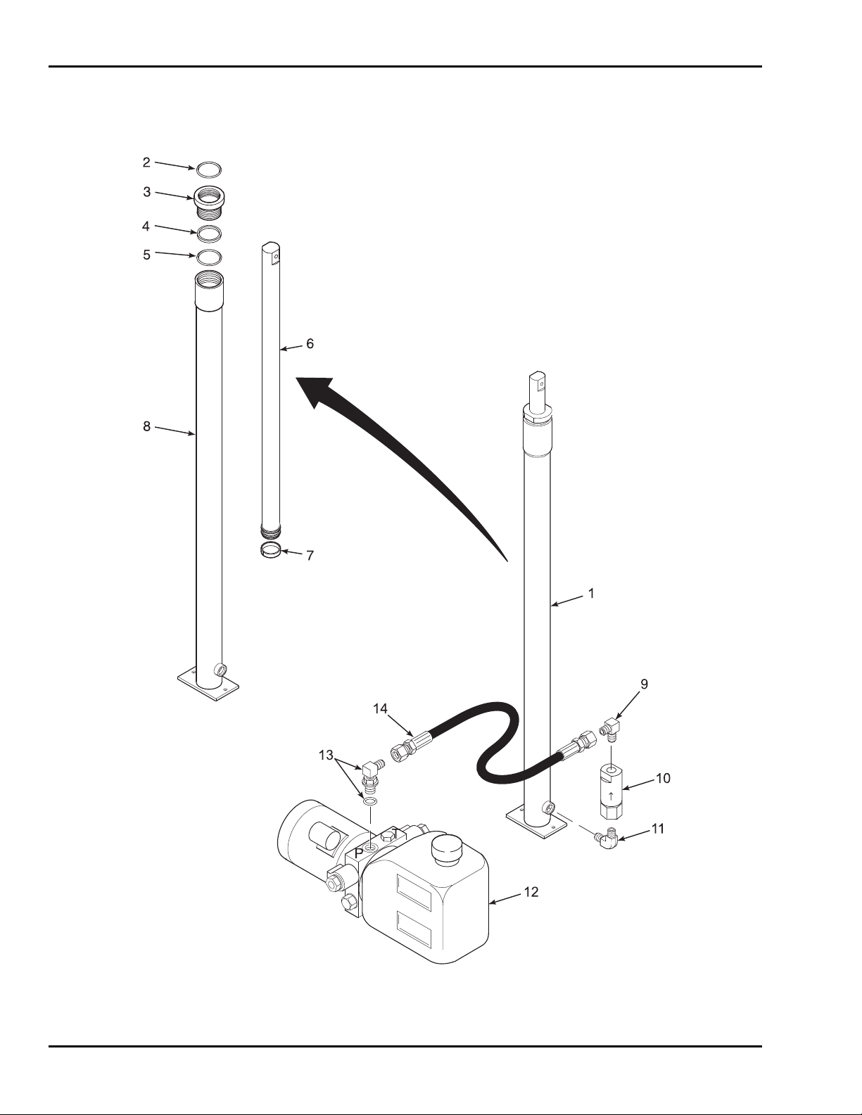
SkyRider 15
6-13 HYDRAULIC CYLINDER, FITTINGS, AND HOSES
PARTS LIST
Figure 6-13. Hydraulic Cylinder, Fittings, and Hoses
6-26
Page 77

6 — PARTS LIST
Table 6-13. Hydraulic Cylinder, Fittings, and Hoses Parts List
Item No. Part No. Description Qty
1 B02-03-0018 Cylinder, Hydraulic Lift, 1.5 in. Diameter 1
2 Wiper, Rod 1
3 B02-13-0096 Nut, Gland 1
4 Packing 1
5 O-Ring 1
6 NSS Piston Rod 1
7 Ring, Wear 1
8 NSS Jacket, Cylinder 1
9 B02-02-0002
Fitting, 4JIC-4NPT 90°
1
10 B02-04-0002 Valve, Flow Control, 1.25 in. 1
11 B02-02-0041
Fitting, 4NPT-4NPT 90°
1
12 B02-05-0027 Pump, Hydraulic 1
13 B02-02-0072
Fitting, 4JIC – 4ORM 90°
14 B02-01-0124 Hose, Hydraulic, 4M3K x 15 in.
1
1
w/2ea. 4-4FJX fittings
B02-13-0097 Seal Kit (Includes items 2, 4, 5, and 7
NSS – Not Sold Separately
6-27
Page 78

SkyRider 15
6-28
Page 79

7
ANSI Reprint
The following sections are reprinted from the ANSI A92.6-1999 code in effect at the
time of manufacture. Permission to reprint has been granted by the Scaffold
Industry Association.
5. Responsibilities of Dealers
5.1 Basic Principles. Sound principles of safety, training, inspection, maintenance,
application, and operation consistent with all data available regarding the parameters
intended use and expected environment shall be applied in the training of operators, in
maintenance, application, safety provisions and operation of the aerial platform with due
consideration of the knowledge that the aerial platform will be carrying personnel.
5.2 Manuals.
5.2.1 Machine manual(s). Dealers shall keep and maintain copy(s) of the (1)
Operating manual. (2) Maintenance manual. (3) Parts manual. (4) Repair manual.
The operating manual and maintenance manual shall be provided with each rental,
lease or sale delivery and shall be stored in the weather resistant storage
compartment on the aerial platform. Manual(s) are considered an integral part of the
aerial platform and are vital to communicate necessary safety information to owners,
users and operators. In addition, repair and parts manuals should be provided with
each sale delivery.
5.2.2 Manual of responsibilities. The ANSI/SIA A92.6-1999 Manual of
Responsibilities for Dealers, Owners, Users, Operators, Lessors, Lessees, and
Brokers of Self-Propelled Elevating Work Platforms shall be provided and stored in
the weather resistant storage compartment.
5.3 Pre-delivery Preparation. Aerial platforms shall be inspected, serviced, and
adjusted to manufacturer's requirements prior to each delivery by sale, lease, or rental.
5.4 Maintenance, Inspection And Repair.
5.4.1 Maintenance. When a dealer accomplishes preventative maintenance on the
aerial platform, it shall be in accordance with the manufacturer’s recommendations
and based on the environment and severity of use.
5.4.2 Inspection. When the dealer accomplishes frequent and annual inspections,
they shall be accomplished in accordance with the manufacturer’s manuals.
5.4.3 Repairs. Repairs accomplished to correct malfunctions and problems shall be
in accordance with the manufacturer’s manuals and instructions.
5.5 Maintenance Safety Precautions. Before adjustments and repairs are started on an
aerial platform, the following precautions shall be taken as applicable: (1) Powerplant
stopped and starting means rendered inoperative; (2) All controls in the "Off" position
and all operating features secured from inadvertent motion by brakes, blocks, or other
means; (3) Elevating assembly and platform lowered down to the full down position, if
possible, or otherwise secured by blocking or cribbing to prevent dropping; (4) Hydraulic
oil pressure relieved from all hydraulic circuits before loosening or removing hydraulic
components; (5) Safety props or latches installed where applicable as prescribed by the
manufacturer.
5.6 Replacement Parts. When parts or components are replaced, they shall be identical
or equivalent to original aerial platform parts or components
5.7 Training. The dealer shall offer appropriate training to facilitate owners, users, and
operators to comply with requirements set forth in this standard regarding the inspection,
maintenance, use, application, and operation of the aerial platform.
7-1
Page 80

SkyRider 15
5.8 Familiarization On Delivery. Upon delivery by sale, lease, rental or any form of
use, the dealer shall have the responsibility with the person designated by the receiving
entity for accepting the aerial platform to: 1) Identify the weather resistant compartment
(for manual storage). 2) Confirm the manuals, as specified by the manufacturer, are on
the aerial platform. 3) Review control functions. 4) Review safety devices specific to
the model aerial platform being delivered.
5.9 Dealer As User. Whenever a dealer directs personnel to operate an aerial platform
(loading, unloading, inspecting, sales demonstrations, or any form of use), the dealer
shall assume the responsibilities of users as specified in Section 7 of this standard. All
personnel authorized to operate the aerial platform shall have been: (1) Trained. (2)
Familiarized with the aerial platform to be operated. (3) Made aware of the
responsibilities of the operators as outlined in Section 8 of this standard.
5.10 Assistance To Owners And Users. If a dealer is unable to answer an owner's or
user's question(s) relating to rated capacity, intended use, maintenance, repair, inspection,
or operation of the aerial platform, the dealer shall obtain the proper information from the
manufacturer or a qualified person if the manufacturer is no longer in business and
provide that information to the owner or user.
5.11 Record Retention And Dissemination.
5.11.1 Record retention. The dealer shall retain the following records for at least 4
years: (1) Name and address of the purchaser of each aerial platform by serial
number and the date of delivery. (2) Records of the pre-delivery preparation
performed prior to each delivery. (3) Records of frequent and annual machine
inspections accomplished. (4) Records of repairs accomplished to correct
malfunctions and problems. (5) Name of the person(s) trained. (6) Name of the
person(s) providing the training. (7) Date of training. (8) Name of person(s)
receiving familiarization with the aerial platform upon each delivery unless this
individual has been provided with familiarization on the same model, or one h aving
characteristics consistent with the one being delivered, within th e prior 90 days.
5.11.2 Proof of training. The dealer should provide trainees who successfully
complete training a means to evidence they are trained. The dealer shall provide
such proof if requested by the trainee. The document evidencing the training shall
include the following information: (1) Name of entity providing training or
retraining. (2) Name of trainer(s). (3) Clear identification that training covered SelfPropelled Elevating Work Platforms. (4) Date of training.
5.11.3 Record dissemination. Upon request, the dealer shall provide the following
information: (1) To the owner of the aerial platform, a copy of frequent or annual
inspections performed. (2) To the owner of the aerial platform, a copy of repairs
accomplished. (3) To a user, proof of training for an operator, including name of
trainer and date of training. (4) To a user, the name of the person(s) receiving
familiarization upon delivery of the aerial platform.
5.12 Modifications. Modification, alteration or remanufacture of an aerial platform
shall be made only with prior written permission of the manufacturer.
5.13 Manufacturer's Safety Bulletins. The dealer shall comply with safety-related
bulletins as received from the manufacturer.
5.14 Responsibilities Upon Sale. When the aerial platform is sold, the dealer: (1) Shall,
upon delivery, ensure the operating and maintenance manuals are conveyed to the owner.
(2) Shall, upon delivery, provide a copy of the ANSI/SIA A92.6-1999 Manual of
Responsibilities for Dealers, Owners, Users, Operators, Lessors, Lessees, and Brokers of
Self-Propelled Elevating Work Platforms. (3) Should, within 60 days of sale, provide
repair and parts manuals. (4) Shall, within 60 days of the sale, notify the manufacturer or
its successor (if existing) of the sale, providing the full name and address of the
purchaser. (5) Should, if the aerial platform is used, accomplish an annual machine
inspection prior to delivery and provide a copy to the purchaser within 60 days of the
sale. (6) Shall, upon delivery, familiarize the person designated by the receiving entity
with the aerial platform being acquired.
7-2
Page 81

7 — ANSI REPRINT
6. Responsibilities of Owners
6.1 Basic Principles. Sound principles of safety, training, inspection, maintenance,
application, and operation consistent with all data available regarding the parameters of
intended use and expected environment shall be applied in the performance of the
responsibilities of owners with due consideration of knowledge that the aerial platform
will be carrying personnel.
6.2 Responsibilities Upon Purchase. Upon purchase of the aerial platform, the buyer:
(1) Shall ensure the operating and maintenance manuals have been received. (2) Should
acquire repair and parts manuals within 60 days of acquisition. (3) Shall within 60 days
of acquisition of the aerial platform provide the manufacturer with the full name and
address of the buyer along with the model and serial number of the aerial platform
acquired. (4) Shall, if the aerial platform is used, perform either a frequent inspection, or
an annual inspection, prior to placing the unit in service. (5) Shall become familiar with
and conform with the responsibilities of owners as set forth in the ANSI/SIA A92.6-1999
Manual of Responsibilities for Dealers, Owners, Users, Operators, Lessors, Lessees, and
Brokers of Self-Propelled Elevating Work Platforms.
6.3 Manuals.
6.3.1 Machine manual(s). Owners shall provide a copy(s) of the operating and
maintenance manual(s) with each rental, lease, or sales delivery by ensuring they are
properly stored in the weatherproof compartment that is a part of the aerial platform.
The manual(s) is considered an integral part of the aerial platform and is vital to
communicate necessary safety information to owners, users and operators. In
addition, repair and parts manuals should be provided with each sale delivery.
6.3.2 Manual of responsibilities. The ANSI/SIA A92.6-1999 Manual of
Responsibilities for Dealers, Owners, Users, Operators, Lessors, Lessees, and
Brokers of Self-Propelled Elevating Work Platforms shall be provided and stored in
the weather resistant storage compartment.
6.4 Maintenance, Inspection And Repair.
6.4.1 Maintenance. The owner of an aerial platform shall arrange that the
maintenance specified in this standard be properly performed on a timely basis. The
owner shall establish a preventive maintenance program in accordance with the
manufacturer's recommendations and based on the environment and severity of use
of the aerial platform.
6.4.2 Inspection. The owner shall arrange for frequent and annual inspections to be
performed as specified by the manufacturer. All malfunctions and problems
identified in the inspection shall be corrected before the aerial platform is returned to
service.
6.4.3 Repairs. When the aerial platform is damaged or in need of repair, all
malfunctions and problems identified shall be corrected before the aerial platform is
returned to service.
6.5 Pre-delivery Preparation. Aerial platforms shall be inspected, serviced, and
adjusted to manufacturer’s requirements prior to each delivery by sale, lease or rental.
6.6 Frequent Inspection. The owner of an aerial platform shall ensure that a frequent
inspection is performed in accordance with the manufacturer’s instructions on an aerial
platform: (1) That has been in service for 3 months or 150 hours, whichever occurs first;
(2) That has been out of service for a period longer than 3 months; (3) That was
purchased used. This inspection shall be accomplished prior to the aerial platform being
placed in service.
The inspection shall be made by a person qualified as a mechanic on the specific make
and model of the aerial platform. The inspection shall include all items specified by the
manufacturer for a frequent inspection and shall include, but not be limited to, the
following: (1) All functions and their controls for speed(s), smoothness, and limits of
motion; (2) Lower controls including the provisions for overriding of upper controls;
(3) All chain and cable mechanisms for adjustment and worn or damaged parts; (4) All
7-3
Page 82

SkyRider 15
emergency and safety devices; (5) Lubrication of all moving parts, inspection of filter
element(s), hydraulic oil, engine oil, and coolant, as specified by the manufacturer; (6)
Visual inspection of structural components and other critical components such as
fasteners, pins, shafts, and locking devices; (7) Placard, warnings, and control markings;
(8) Additional Items specified by the manufacturer.
The owner shall not place the aerial platform into service until all malfunctions and
problems have been corrected.
6.7 Annual Inspection. The owner of an aerial platform shall ensure that an annual
inspection is performed on the aerial platform no later than 13 months from the date of
the prior annual inspection. The inspection shall be performed by a person(s) qualified
as a mechanic on the specific make and model of the aerial platform. The inspection
shall include all items specified by the manufacturer for an annual inspection.
6.8 Maintenance Safety Precautions. Before adjustments and repairs are started on an
aerial platform, the following precautions shall be taken as applicable: (1) Powerplant
stopped and starting means rendered inoperative; (2) All controls in the "off" position
and all operating systems secured from inadvertent motion by brakes, blocks, or other
means; (3) Elevating assembly and platform lowered to the full down position, if
possible, or otherwise secured by blocking or cribbing to prevent dropping; (4)
Hydraulic oil pressure relieved from all hydraulic circuits before loosening or removing
hydraulic components; (5) Safety props or latches installed where applicable as
prescribed by the manufacturer.
6.9 Replacement Parts. When parts or components are replaced, they shall be
identical or equivalent to original aerial platform parts or components.
6.10 Maintenance And Inspection Training. The owners shall train their maintenance
personnel in inspection and maintenance of the aerial platform in accordance with the
manufacturer's recommendations and sections 6.2-6.11 of this standard.
6.11 Training.
6.11.1 Operator training. Whenever an owner directs or authorizes an employee
to operate an aerial platform (loading, unloading, inspecting or any form of use) the
owner shall assume the responsibilities of the user as specified in Section 7 of this
standard and shall ensure that the person has been: (1) Trained. (2) Familiarized
with the aerial platform to be operated. (3) Made aware of the responsibilities of
operators as outlined in Section 8 of this standard.
6.11.2 Assistance to user. Upon request of the user, when an owner sells, leases,
rents or provides an aerial platform for any form of beneficial use, the owner at that
time shall offer to do training or advise the user where training may be reasonably
secured.
6.12 Familiarization Upon Delivery. Upon delivery for lease, rental or any form of
beneficial use, the owner shall have the responsibility with the person designated by the
receiving entity for accepting the aerial platform to: 1) Identify the weather resistant
compartment (for manual storage). 2) Confirm the manuals, as specified by the
manufacturer, are on the aerial platform. 3) Review control functions with the operator
or person(s) designated by the user. 4) Review safety devices specific to the model aerial
platform being delivered.
6.13 Operation. When an owner operates an aerial platform, the owner shall have the
responsibilities of users as specified in Section 7 of this standard, and the operating
personnel shall have responsibilities of operators as specified in Section 8 of this
standard.
6.14 Assistance To Users And Operators. If an owner is unable to answer a user's or
operator's question(s) relating to rated capacity, intended use, maintenance, repair,
inspection, or operation of the aerial platform, the owner shall obtain the proper
information from the dealer or manufacturer and provide that information to user or
operator.
7-4
Page 83

7 — ANSI REPRINT
6.15 Record Retention And Dissemination.
6.15.1 Record retention. The owner shall retain the following records for at least 4
years: (1) Name and address of the purchaser of each aerial platform by serial
number and date of delivery. (2) Written records of the frequent and annual
inspections and repairs performed. The record shall include deficiencies found,
corrective action accomplished and identification of the person(s) performing the
inspection and repairs. (3) Written records of repairs accomplished on the aerial
platform. The records shall include corrective action accomplished and
identification of the person(s) performing the repairs. (4) Predelivery preparation
performed prior to each delivery. (5) Name of the person(s) trained. (6) Name of
the person(s) providing training. (7) Name of the person(s) provided with
familiarization upon delivery unless this individual has been provided with
familiarization on the same model, or one having characteristics consistent with the
one being delivered, within the prior 90 days. (8) Name of person(s) providing
familiarization upon delivery.
6.15.2 Proof of training. Owners providing training should provide successful
trainees a means to evidence their training and shall provide such proof if requested
by the trainee. The document evidencing the training shall include the following
information: (1) Name of entity providing training or retraining. (2) Name of
trainer(s). (3) Clear identification that training covered Self-Propelled Elevating
Work Platforms. (4) Date of training.
6.15.3 Record dissemination. Upon request, an owner accomplishing training
and/or familiarization shall provide the following: (1) To a user, proof of training
for an operator, including name of trainer and date of training; (2) To a user, the
name of the person(s) receiving familiarization upon delivery of the aerial platform.
6.16 Modifications. Modification, alteration or remanufacture of an aerial platform
shall be made only with prior written permission of the manufacturer.
6.17 Manufacturer's Safety Bulletins. The owner shall comply with safety-related
bulletins as received from the manufacturer or the dealer.
6.18 Responsibilities Upon Sale. When the aerial platform is sold, the seller: (1) Shall,
upon delivery, ensure the operating and maintenance manuals are conveyed to the new
owner. (2) Shall, upon delivery, provide a copy of the ANSI/SIA A92.6-1999 Manual of
Responsibilities for Dealers, Owners, Users, Operators, Lessors, Lessees, and Brokers of
Self-Propelled Elevating Work Platforms. (3) Should provide repair and parts manuals
to the new owner. (4) Shall, upon the request of the new owner, offer to do training or
advise where training may reasonably be obtained.
7. Responsibilities of Users.
7.1 Basic Principles. The information in this standard must be supplemented by good
job management, safety control, and the application of sound principles of safety,
training, inspection, maintenance, application, and operation consistent with all data
available regarding the parameters of intended use and expected environment. Since the
user has direct control over the application and operation of aerial platforms,
conformance with good safety practices in this area is the responsibility of the user and
the operating personnel, including the operator. Decisions on the use and operation of
the aerial platform must always be made with due consideration for the fact that the aerial
platform will be carrying personnel whose safety is dependent on those decisions.
7.2 Manuals.
7.2.1 Machine manuals. Users shall keep and maintain a copy(s) of the operating
and maintenance manual(s) in the weather resistant storage compartment provided
by the manufacturer. The manual(s) is considered an integral part of the aerial
platform and is vital to communicate necessary safety information to users and
operators.
7.2.2 Manual of responsibilities. The ANSI/SIA A92.6-1999 Manual of
Responsibilities for Dealers, Owners, Users, Operators, Lessors, Lessees, and
7-5
Page 84

SkyRider 15
Brokers of Self-Propelled Elevating Work Platforms shall be provided and stored in
the weather resistant storage compartment.
7.3 Inspection And Maintenance. Users shall inspect and maintain the aerial platform
as required to ensure proper operation. The frequency of inspection and maintenance
shall be determined by the manufacturer's recommendations and be compatible with
operating conditions and the severity of the operating environment. Aerial platforms that
are not in proper operating condition shall be immediately removed from service until
repaired. Repairs shall be made by a qualified person and the repairs shall be in
conformance with the manufacturer's recommendations.
7.3.1 Frequent Inspection. Users of an aerial platform shall ensure that frequent
inspections are conducted as outlined in section 6.6 of this standard.
7.3.2 Annual Inspection. Users of an aerial platform shall ensure that annual
inspections are conducted as outlined in section 6.7 of this standard.
7.3.3 Pre-start Inspection. Before use each day or at the beginning of each shift,
the aerial platform shall be given a visual inspection and functional test including but
not limited to the following: (1) Operating and emergency controls. (2) Safety
devices. (3) Personal protective devices. (4) Air, hydraulic and fuel system leaks.
(5) Cables and wiring harness. (6) Loose or missing parts. (7) Tires and wheels. (8)
Placards, warnings, control markings, and operating manual(s). (9) Outriggers,
stabilizers, and other structures. (10) Guardrail system . (11) Items specified by the
manufacturer.
7.3.4 Maintenance Safety Precautions. Before adjustments and repairs are started
on an aerial platform, the following precautions shall be taken as applicable: (1)
Powerplant stopped and starting means rendered inoperative; (2) All controls in the
"Off" position and all operating systems secured from inadvertent motion by brakes,
blocks, or other means; (3) Elevating assembly and platform lowered to the full
down position, if possible, or otherwise secured by blocking or cribbing to prevent
dropping; (4) Hydraulic oil pressure relieved from all hydraulic circuits before
loosening or removing hydraulic components; (5) Safety props or latches installed
where applicable as prescribed by the manufacturer.
7.4 Replacement Parts. When parts or components are replaced, they shall be identical
or equivalent to original aerial platform parts or components.
7.5 Maintenance Training. The user shall insure only qualified personnel inspect and
maintain the aerial platform in accordance with the manufacturer's recommendations and
sections 7.3 and 7.4 of this standard.
7.6 Operator Training And Retraining. Whenever a user directs or authorizes an
individual to operate an aerial platform the user shall ensure the person has been: (1)
Trained before being assigned to operate the aerial platform. (2) Familiarized with the
aerial platform to bo operated. (3) Made aware of responsibilities of operators as
outlined in Section 8 of this standard. (4) Retrained, if necessary, based on the user’s
observation and evaluation of the operator.
7.6.1 Trainee records. A record of the trainee's aerial platform instruction shall be
maintained by the user for at least 4 years.
7-6
Page 85

7 — ANSI REPRINT
7.7 Familiarization Before Use. The user shall permit only properly trained personnel
to operate an aerial platform. The user shall ensure that before use the operator is
familiar with the model of the aerial platform to be operated, and specifically: (1) Knows
where the weather resistant compartment for manual storage is located. (2) Knows the
operating and maintenance manuals supplied by the manufacturer are stored in the
weather resistant compartment and is familiar with the operating and safety manuals. (3)
Understands all control functions, placards and warnings. (4) Is aware of and
understands all safety devices specific to the model aerial platform being used.
7.8 Workplace Inspection. Before the aerial platform is used and during use, the user
shall check the area in which the aerial platform is to be used for possible hazards such
as, but not limited to: (1) Drop-offs or holes. (2) Slope(s). (3) Bumps and floor
obstructions. (4) Debris. (5) Overhead obstructions and high voltage conductors. (6)
Hazardous locations and atmospheres (reference ANSI/NFPA 505-1996). (7) Inadequate
surface and support to withstand all load forces imposed by the aerial platform in all
operating configurations. (8) Wind and weather conditions. (9) Presence of
unauthorized persons. (10) Other possible unsafe conditions.
7.9 Determination Of Hazardous Locations. It shall be the responsibility of the user
to determine the hazard classification (potential presence of flammable or explosive
gases or particles) of the intended location of operation. Aerial platforms operated in
hazardous locations shall be approved in accordance with, and of the type required, by
ANSI/NFPA 505-1996.
7.10 Operator Warnings And Instructions. The user shall direct personnel operating
the aerial platform to be in compliance with the provisions set forth in this standard. The
user shall monitor their performance and supervise their work to ensure the use,
application and operation of the aerial platform is in conformance with the provisions set
forth in this standard, warn personnel of potential hazards, provide means to protect
against identified hazards, and explain the potential consequences of not following
proper operating guidelines. Instructions and guidelines regarding proper operation shall
include, but not necessarily be limited to, the following issues and subjects: (1) Fall
protection. The guardrail system of the aerial platform provides fall protection. If
worksite rules require an occupant(s) of the platform to wear restraint or body
positioning devices, occupants shall comply with instructions provided by the aerial
platform manufacturer regarding anchorage(s). (2) Slope and grade. The aerial platform
shall not be operated in any manner on grades, side slopes or ramps exceeding those for
which the aerial platform is rated by the manufacturer. (3) Deployment of stability
enhancing means. Outriggers, stabilizers, extendible axles, oscillating axles or other
stability enhancing means shall be deployed and locked into place as required by the
manufacturer. (4) Guardrail system. Guardrails shall be installed and positioned, and
access gates or openings shall be closed per the manufacturer’s instructions. (5)
Distribution of load. The load and its distribution on the platform and any platform
extension(s) shall be in accordance with manufacturer’s rated capacity for that specific
configuration. (6) Maintaining overhead clearance. The operator shall be instructed to
ensure that adequate clearance is maintained from overhead obstructions and energized
electrical conductors and parts. (7) Electrocution hazard. The user shall direct the
operator to maintain, and provide the means to maintain the minimum safe approach
distance (MSAD) from energized power lines and parts, as listed in Table 7-1 on pages
7-14 & 7-15. Electrical equipment and lines shall be consid ered energized until
determined to be de-energized by tests or other appropriate methods or means and
properly grounded. If energized power lines or parts are within the area in which the
aerial platform is to be used, the user shall define and explain to the operator specific
means to maintain the minimum safe approach distance required. (8) Personal protective
equipment. The user shall direct the operator to ensure all personnel on the platform
wear personal protective equipment as required. (9) Personnel footing. Personnel shall
maintain a firm footing on the platform floor while working thereon. Climbing by
occupants on the midrail or toprail of the aerial platform is prohibited. The use of planks,
ladders, or any other device on the aerial platform for achieving additional height or
7-7
Page 86

SkyRider 15
reach is prohibited. (10) Precaution for other moving equipment. When other moving
equipment and vehicles are present, special precautions shall be taken to comply with
local ordinances or safety standards established for the workplace. Warnings such as, but
not limited to, flags, roped-off areas, flashing lights, and barricades shall be used as
appropriate. (11) Reporting problems or malfunctions. The user shall direct the operator
to immediately report to a supervisor any problem(s) or malfunction(s) that become
evident during operation. The user shall ensure all problems and malfunctions that affect
the safety of operations are repaired prior to continued use. (12) Reporting potentially
hazardous locations. The user shall direct the operator to immediately report to a
supervisor any potentially hazardous location(s) (one having potentially flammable or
explosive gases or particles) that become evident during operation. (13) Hazardous
location operation. Operation of aerial platforms not approved and marked for operation
in a hazardous location (one having potentially flammable or explosive gases or
particles) shall be prohibited. (14) Entanglement. Care shall be taken to prevent rope,
electric cords, and hoses, etc., from becoming entangled in the aerial platform. (15)
Capacity limitations. Rated capacities shall not be exceeded when loads are transferred
to the platform at any height. (16) Work area. The operator shall ensure the area
surrounding the aerial platform is clear of personnel and equipment before lowering the
platform. (17) Fueling. The engine (if applicable) shall be shut down while fuel tanks
are being filled. Fueling shall be done in a well-ventilated area free of flame, sparks, or
other hazards that may cause fire or explosion. (18) Battery charging. Batteries shall
only be charged in a well-ventilated area free of flame, sparks, or other hazards that may
cause fire or explosion. (19) Improper platform stabilization. The aerial platform shall
not be positioned against another object to steady the platform. (20) Misuse as a crane.
The aerial platform shall not be used as a crane. (21) Unusual operating support
conditions. The aerial platform shall not be operated from a position on trucks, trailers,
railway cars, floating vessels, scaffolds, or similar equipment unless the application is
approved in writing by the manufacturer or a qualified person. (22) Travel speeds. The
operator shall limit travel speed according to conditions, including the condition of the
support surface, congestion, visibility, slope, location of personnel, and other factors
leading to hazards which may cause collision(s) or result in potential injury(s) to
personnel. (23) Elevated driving requirements. Before and during driving while the
platform is elevated, the operator shall: (a) Maintain a clear view of the support surface
and route of travel. (b) Ensure personnel in the worksite area that may be affected are
aware of the movement, communicating and maneuvering the aerial platform as required
to protect against personal injury. (c) Maintain a safe distance from obstacles, debris,
drop-offs, holes, depressions, ramps, and other hazards to ensure safe travel. (d)
Maintain a safe distance from overhead obstacles. (24) Stunt driving. Stunt driving and
horseplay are prohibited. (25) Securing the aerial platform. The user shall direct the
operator to implement means provided to protect against use by unauthorized person(s).
(26) Altering safety devices. Interlocks or other safety devices shall not be altered or
disabled. (27) Snagged platform. If the platform/basket or supporting assembly becomes
caught, snagged, or otherwise prevented from normal motion by adjacent structures or
other obstacles such that control reversal does not free the platform, all personnel shall be
removed from the platform/basket before attempts are made to free the platform using
lower controls. (28) Vacating (or entering) an elevated aerial platform. If permitted by
the manufacturer, personnel shall only vacate or enter a raised aerial platform by
following the guidelines and instructions provided by the manufacturer. (29)
Modifications. Modification or alteration of an aerial platform or the fabrication and
attaching of frameworks, or the mounting of attachments for holding tools or materials
onto the platform or the guardrail system shall only be accomplished with the prior
written permission of the manufacturer. (30) Assistance to the operator. If an operator
encounters any suspected malfunction of the aerial platform, or any hazard or potentially
unsafe condition relating to capacity, intended use or safe operation of the aerial
platform, the operator shall cease operation of the aerial platform and request further
information from the employer. (31) Problems or malfunctions. Any problem(s) or
malfunction(s) that affect the safety of operations shall be repaired prior to use of the
aerial platform. (32) Carrying materials (larger than the platform). The user shall ensure
7-8
Page 87

7 — ANSI REPRINT
that only tools and materials, which are evenly distributed and can be safely handled by a
person(s) working from the platform, are transported. (33) Rated horizontal force. The
user shall direct the operator not to exceed the manufacturer’s rated horizontal force.
(34) Bridge cranes. When an aerial platform is to operate within the area of travel of a
bridge crane or similar equipment, steps shall be taken to prevent a collision with the
aerial platform. (35) Adequate support requirements. The user shall insure the support
surface is adequate for the aerial platform and the load carried. (36) Leveling the aerial
platform. Outriggers and leveling devices supplied by the manufacturer shall be utilized
to level the aerial platform when provided. (37) Protecting against unauthorized use.
The user shall direct the operator not to use, rent, lease, or provide the aerial platform for
any form of beneficial use unless so authorized.
7.11 User As Operator. If a user is also the operator of an aerial platform, the user shall
have the responsibilities of operators specified in Section 8 of this standard as well as
responsibilities of users as specified in Section 7 of this standard.
7.12 Shutdown Of Aerial Platform. The user shall authorize and direct the operating
personnel to cease operation of the aerial platform in case of any suspected malfunctions
of the aerial platform, or any hazard or potentially unsafe condition that may be
encountered, and to request further information as to safe operation from the owner,
dealer, or manufacturer before further operation of the aerial platform.
7.13 Record Retention And Dissemination.
7.13.1 Record retention. The user shall retain the following records for at least 4
years: (1) Names of the operator(s) trained and retrained. (2) Names of operator(s)
provided familiarization. (3) The owner (or entity designated by the owner) is
responsible to ensure frequent and annual inspections are conducted and written
records are maintained. The records shall include the date of the inspection, any
deficiencies found, the corrective action recommended and identification of the
person(s) performing the inspection. (4) When employees of the user accomplish
repairs on the aerial platform, the user shall maintain written records. The record
shall include the date of repair, a description of the work accomplished, and
identification of the person(s) performing the repair.
7.13.2 Record dissemination. (1) When the user directs personnel to accomplish
frequent or annual inspections, not later than 60 days after the inspections, the
appropriate records shall be provided to the owner of the aerial platform. (2) When
the user directs personnel to accomplish repairs on the aerial platform, not later than
60 days after the repairs are accomplished, the appropriate records shall be provided
to the owner.
7.13.3 Proof of training. Users providing training should provide successful
trainees a means to evidence their training and shall provide such proof if requested
by the trainee. The document evidencing the training shall include the following
information: (1) Name of entity providing training or retraining. (2) Name of
trainer(s). (3) Clear identification that training covered Self-Propelled Elevating
Work Platforms. (4) Date of training.
7.14 Modifications. Modification, alteration or remanufacture of an aerial platform
shall be made only with prior written permission of the manufacturer.
7.15 Manufacturer's Safety Bulletins. The user shall comply with safety related
bulletins as received from the manufacturer, dealer, or owner.
8. Responsibilities Of Operators
8.1 Basic Principles. The information in this standard shall be supplemented by good
judgment, safety control, and caution in evaluating each situation. Since the
operator is in direct control of the aerial platform, conformance with good safety
practices in this area is the responsibility of the operator. The operator shall make
decisions on the use and operation of the aerial platform with due consideration for
the fact that his or her own safety as well as the safety of others is dependent on
those decisions.
7-9
Page 88

SkyRider 15
8.2 Manuals.
8.2.1 Machine manuals. The operator shall ensure the operating and maintenance
manuals are stored in the weather resistant storage compartment on the aerial
platform. The manual(s) is considered an integral part of the aerial platform and is
vital to communicate necessary safety information to the operator. The operator
shall be familiar with the manuals and reference them as required.
8.2.2 Manual of responsibilities. The ANSI/SIA A92.6-1999 Manual of
Responsibilities for Dealers, Owners, Users, Operators, Lessors, Lessees, and
Brokers of Self-Propelled Elevating Work Platforms shall be provided and stored in
the weather resistant storage compartment.
8.3 Pre-start Inspection. Before use each day or at the beginning of each shift, the
aerial platform shall be given a visual inspection and functional test including but not
limited to the following: (1) Operating and emergency controls. (2) Safety devices. (3)
Personal protective devices. (4) Air, hydraulic, and fuel system leaks. (5) Cables and
wiring harness. (6) Loose or missing parts. (7) Tires and wheels. (8) Placards,
warnings, control markings, and operating manuals. (9) Outriggers, stabilizers, and other
structures. (10) Guardrail system. (11) Items specified by the manufacturer.
8.4 Problems Or Malfunctions. Any problems or malfunctions that affect the safety of
operations shall be repaired prior to the use of the aerial platform.
8.5 Training, Retraining, And Familia rization.
8.5.1 General training. Only personnel who have received general instructions
regarding the inspection, application and operation of aerial platforms, including
recognition and avoidance of hazards associated with their operation, shall operate
an aerial platform. Such items covered shall include, but not necessarily limited to,
the following issues and requirements: (1) The purpose and use of manuals. (2)
That operating manuals are an integral part of the aerial platform and must be stored
properly in the weather resistant compartment when not in use. (3) A pre-start
inspection. (4) Responsibilities associated with problems or malfunctions affecting
the operation of the aerial platform. (5) Factors affecting stability. (6) The purpose
of placards and decals. (7) Workplace inspection. (8) Safety rules and regulations.
(9) Authorization to operate. (10) Operator warnings and instructions. (11) Actual
operation of the aerial platform. Under the direction of a qualified person, the
trainee shall operate the aerial platform for a sufficient period of time to demonstrate
proficiency in the actual operation of the aerial platform.
8.5.2 Retraining. The operator shall be retrained, when so directed by the user,
based on the user’s observation and evaluation of the operator.
8.5.3 Familiarization. When an operator is directed to op erate an aerial platform
he/she is not familiar with, the operator shall receive instructions regarding the
following items: (1) The location of the weather resistant compartment (for manual
storage). (2) The purpose and function of all controls. (3) Safety devices and
operating characteristics specific to the aerial platform.
8.6 Before Operation. Before operation, the operator shall: (1) Read and understand
the manufacturer's operating instruction(s) and user’s safety rules or have them
explained. (2) Understand all labels, warnings, and instructions displayed on the aerial
platform or have them explained. (3) Ensure all occupants of the aerial platform wear
appropriate personal safety equipment for the conditions, including the environment in
which the aerial platform will be operated.
8.7 Workplace Inspection. Before the aerial platform is used and during use, the
operator shall check the area in which the aerial platform is to be used for possible
hazards such as, but not limited to: (1) Drop-offs or holes. (2) Slope(s). (3) Bumps and
floor obstructions. (4) Debris. (5) Overhead obstructions and electrical conductors. (6)
Hazardous locations. (7) Inadequate surface and support to withstand all load forces
imposed by the aerial platform in all operating configurations. (8) Wind and weather
conditions. (9) Other possible unsafe conditions.
7-10
Page 89

7 — ANSI REPRINT
8.8 Prior To Each Elevation. Before each elevation of the platform, the operator shall
ensure: (1) Outriggers, stabilizers, extendable axles, or other stability enhancing means
are used as required by the manufacturer. (2) Guardrails are installed and access gates or
openings are closed per manufacturer's instructions. (3) The load and its distribution on
the platform and any platform extension(s) are in accordance with the manufacturer's
rated capacity for that specific configuration. (4) All personnel on the aerial platform
have appropriate safety gear for the work and environment envisioned.
8.9 Understanding Of Hazardous Locations. It shall be the responsibility of the
operator to understand the hazard classification (potential presence of flammable or
explosive gases or particles) of the intended location of operation according to
ANSI/NFPA-1996.
8.10 Operator Warnings And Instructions. The operator shall ensure the operation of
the aerial platform is in compliance with the following: (1) Fall protection. The
guardrail system of the aerial platform provides fall protection. If worksite rules require
an occupant(s) of the platform to wear restraint or body positioning devices, occupants
shall comply with instructions provided by the aerial platform manufacturer regarding
anchorage(s). (2) Slope and grade. The aerial platform shall not be operated in any
manner on grades, side slopes or ramps exceeding those for which the aerial platform is
rated by the manufacturer. (3) Deployment of stability enhancing means. Outriggers,
stabilizers, extendible axles, oscillating axles or other stability enhancing means shall be
deployed and locked into place as required by the manufacturer. (4) Guardrail system.
Guardrails shall be installed and positioned, and access gates or openings shall be closed
per the manufacturer’s instructions. (5) Distribution of load. The load and its
distribution on the platform and any platform extension(s) shall be in accordance with
manufacturer’s rated capacity for that specific configuration. (6) Maintaining overhead
clearance. The operator shall ensure adequate clearance is maintained from overhead
obstructions and energized electrical conductors and parts. (7) Electrocution hazard.
The operator shall maintain the minimum safe approach distance (MSAD) from
energized power lines and parts, as listed in Table 7-1on pages 7-14 & 7-15. Electrical
equipment and lines shall be considered energized until determined to b e de-energized by
tests or other appropriate methods or means and properly grounded. If energized power
lines or parts are within the area in which the aerial platform is to be used, the operator
shall maintain the minimum safe approach distance required. (8) Personal protective
equipment. The user operator shall ensure all occupants of the platform wear personal
protective equipment as required. (9) Personnel footing. Personnel shall maintain firm
footing on the platform floor while working thereon. Climbing by occupants on the
midrail or toprail of the aerial platform is prohibited. The use of planks, ladders, or any
other device on the aerial platform for achieving additional height or reach is prohibited.
(10) Precaution for other moving equipment. When other moving equipment and
vehicles are present, special precautions shall be taken to comply with local ordinances
or safety standards established for the workplace. Warnings such as, but not limited to,
flags, roped-off areas, flashing lights, and barricades shall be used as appropriate. (11)
Reporting problems or malfunctions. The operator shall immediately report to a
supervisor any problem(s) or malfunction(s) that become evident during operation. The
operator shall ensure all problems and malfunctions that affect the safety of operations
are repaired prior to continued use. (12) Reporting potentially hazardous locations. The
operator shall immediately report to a supervisor any potentially hazardous location(s)
(one having potentially flammable or explosive gases or particles) that become evident
during operation. (13) Hazardous location operation. Operation of aerial platforms not
approved and marked for operation in a hazardous location (one having potentially
flammable or explosive gases or particles) shall be prohibited. (14) Entanglement. Care
shall be taken to prevent rope, electric cords, and hoses, etc., from becoming entangled in
the aerial platform. (15) Capacity limitations. Rated capacities shall not be exceeded
when loads are transferred to the platform at any height. (16) Work area. The operator
shall ensure the area surrounding the aerial platform is clear of personnel and equipment
before lowering the platform. (17) Fueling. The engine (if applicable) shall be shut
down while fuel tanks are being filled. Fueling shall be done in a well-ventilated area
7-11
Page 90

SkyRider 15
free of flame, sparks, or other hazards that may cause fire or explosion. (18) Battery
charging. Batteries shall only be charged in a well-ventilated area free of flame, sparks,
or other hazards that may cause fire or explosion. (19) Improper platform stabilization.
The aerial platform shall not be positioned against another object to steady the platform.
(20) Misuse as a crane. The aerial platform shall not be used as a crane. (21) Unusual
operating support conditions. The aerial platform shall not be operated from a position
on trucks, trailers, railway cars, floating vessels, scaffolds, or similar equipment unless
the application is approved in writing by the manufacturer or a qualified person. (22)
Travel speeds. The operator shall limit travel speed according to conditions, including
the condition of the support surface, congestion, visibility, slope, location of personnel,
and other factors leading to hazards which may cause collision(s) or result in potential
injury(s) to personnel. (23) Elevated driving requirements. Before and during driving
while the platform is elevated, the operator shall: (a) Maintain a clear view of the
support surface and route of travel. (b) Ensure personnel in the worksite area that may be
affected are aware of the movement, communicating and maneuvering the aerial platform
as required to protect against personal injury. (c) Maintain a safe distance from
obstacles, debris, drop-offs, holes, depressions, ramps, and other hazards to ensure safe
travel. (d) Maintain a safe distance from overhead obstacles. (24) Stunt driving. Stunt
driving and horseplay are prohibited. (25) Securing the aerial platform. The operator
shall implement means provided to protect against use by unauthorized person(s). (26)
Altering safety devices. Interlocks or other safety devices shall not be altered or
disabled. (27) Snagged platform. If the platform/basket or supporting assembly becomes
caught, snagged, or otherwise prevented from normal motion by adjacent structures or
other obstacles such that control reversal does not free the platform, all personnel shall be
removed from the platform/basket before attempts are made to free the platform using
lower controls. (28) Vacating (or entering) an elevated aerial platform. If permitted by
the manufacturer, personnel shall only vacate or enter a raised aerial platform by
following the guidelines and instructions provided by the manufacturer. (29)
Modifications. Modification or alteration of an aerial platform or the fabrication and
attaching of frameworks, or the mounting of attachments for holding tools or materials
onto the platform or the guardrail system shall only be accomplished with the prior
written permission of the manufacturer. (30) Assistance to the operator. If an operator
encounters any suspected malfunction of the aerial platform, or any hazard or potentially
unsafe condition relating to capacity, intended use or safe operation of the aerial
platform, the operator shall cease operation of the aerial platform and request further
information from the employer. (31) Problem(s) or malfunction(s). Any problems or
malfunctions that affect the safety of operations shall be repaired prior to use of the aerial
platform. (32) Carrying materials (larger than the platform). The operator shall ensure
that only tools and materials, which are evenly distributed and can be safely handled by a
person(s) working from the platform, are transported. (33) Rated horizontal force. The
operator shall not permit personnel on the platform to exceed the manufacturer’s
horizontal force. (34) Bridge cranes. When an aerial platform is to operate within the
area of travel of a bridge crane or similar equipment, steps shall be taken to prevent a
collision with the aerial platform. (35) Adequate support requirements. The operator
shall insure the support surface is adequate for the aerial platform and the load carried.
(36) Leveling the aerial platform. Outriggers and leveling devices supplied by the
manufacturer shall be utilized to level the aerial platform when provided. (37) Protecting
against unauthorized use. The operator shall not use, rent, lease, or provide the aerial
platform for any form of beneficial use to another entity without the authorization of the
user.
8.11 Record Of Training. When provided or when obtained upon the operator’s
request, proof of training provided by the training entity should be retained by the
operator. Records shall contain the following information: (1) Name of entity
providing training or retraining. (2) Name of trainer(s). (3) Clear identification
that training covered Self-Propelled Elevating Work Platforms. (4) Date of training.
7-12
Page 91

7 — ANSI REPRINT
9. Responsibilities Of Lessors
9.1 Basic Principles. Sound principles of safety, training, inspections, maintenance,
application, and operation consistent with all data available regarding the parameters of
intended use and expected environment shall be applied in the performance of
responsibilities of lessors with due consideration of the knowledge that the aerial
platform will be carrying personnel.
9.2 Lessor As A Dealer. When a lessor uses the aerial platform as a dealer, the lessor
shall have the responsibilities of dealers as specified in Section 5 of this standard.
9.3 Lessor As An Owner. When a lessor uses the aerial platform as an owner, the
lessor shall have responsibilities of owners as specified in Section 6 of this standard.
9.4 Lessor As A User. When a lessor uses the aerial platform as a user, the lessor shall
have the responsibilities of users as specified in Section 7 of this standard.
9.5 Lessor As An Operator. When a lessor uses the aerial platform as an operator, he
shall have the responsibilities of operators as specified in Section 8 of this standard.
10. Responsibilities Of Lessees
10.1 Basic Principles. Sound principles of safety, training, inspections, maintenance,
application, and operation consistent with all data available regarding the parameters of
intended use and expected environment shall be applied in the performance of
responsibilities of lessees with due consideration of the knowledge that the aerial
platform will be carrying personnel.
10.2 Lessee As A Dealer. When a lessee uses the aerial platform as a dealer, he shall
have the responsibilities of dealers as specified in Section 5 of this standard.
10.3 Lessee As An Owner. When a lessee uses the aerial platform as an owner, the
lessee shall have the responsibilities of owners as specified in Section 6 of this standard.
10.4 Lessee As A User. When a lessee uses the aerial platform as a user, the lessee shall
have the responsibilities of users as specified in Section 7 of this standard.
10.5 Lessee As An Operator. When a lessee uses the aerial platform as an operator, the
lessee shall have the responsibilities of operators as specified in Section 8 of this
standard.
11. Responsibilities Of Brokers
11.1 Responsibilities Upon Sale. The broker shall: (1) Upon delivery, ensure the
operating and maintenance manuals are provided to the new owner. (2) Upon delivery,
provide a copy of the ANSI/SIA A92.6-1999 Manual of Responsibilities for Dealers,
Owners, Users, Operators, Lessors, Lessees, and Brokers of Self-Propelled Elevating
Work Platforms. (3) Maintain records of the sale for a minimum of 4 years.
11.2 Responsibilities With Re-rents, Leases, Or Any Other Form Of Beneficial Use.
When compensation is received as a result of a re-rent, lease or any form of beneficial
use of an aerial platform, the broker shall: (1) Upon delivery, ensure the operating and
maintenance manuals are provided to the user. (2) Upon delivery, provide a copy of the
ANSI/SIA A92.6-1999 Manual of Responsibilities for Dealers, Owners, Users,
Operators, Lessors, Lessees, and Brokers of Self-Propelled Elevating Work Platforms.
(3) Ensure operating personnel are familiarized with the aerial platform prior to use. (4)
Retain records of the transaction for a minimum of 4 years.
7-13
Page 92
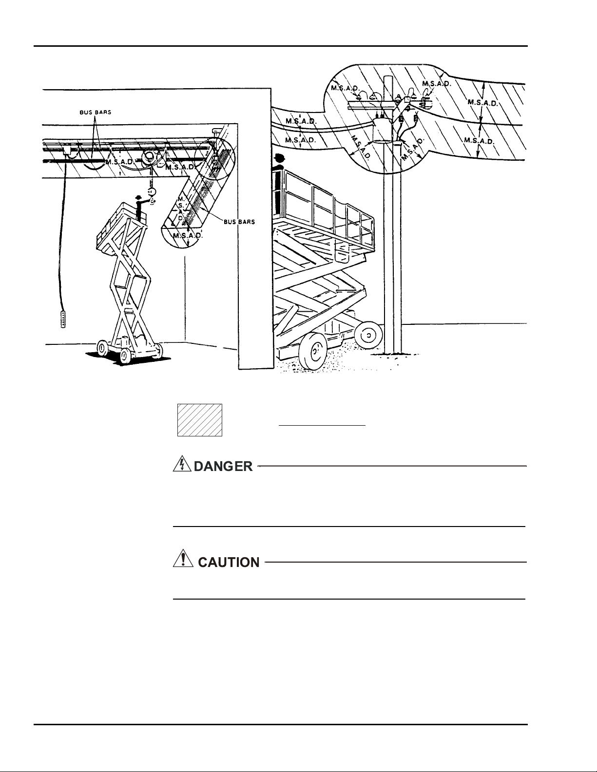
SkyRider 15
M.S.A.D. = Minimum Safe Approach Distance (See
Table 7-1).
DENOTES PROHIBITED ZONE
• Do not allow machine, personnel, or conductive materials inside prohibited zone.
• Maintain M.S.A.D. from all energized lines and parts as well as those shown.
• Assume all electrical parts and wires are energized unless known otherwise.
Diagrams shown are only for purposes of illustrating M.S.A.D. work positions, not
all work positions.
7-14
Page 93

7 — ANSI REPRINT
Table 7-1. Minimum Safe Approach Distance (M.S.A.D.) to energized
(exposed or insulated) power lines and parts
Voltage Range
(Phase to Phase)
Minimum Safe Approach Distance
(Feet) (Meters)
0 to 300V Avoid Contact
Over 300V to 50KV 10 3.05
Over 50KV to 200KV 15 4.60
Over 200KV to 350KV 20 6.10
Over 350KV to 500KV 25 7.62
Over 500KV to 750KV 35 10.67
Over 750KV to 1000KV 45 13.72
7-15
Page 94

SkyRider 15
7-16
Page 95

Page 96

125 Taylor Parkway
Archbold, OH 43502
Phone (419) 445-8915
(800) 537-0540
Fax (419) 445-0367
http://www.biljax.com
 Loading...