

Page 1

AERIAL WORK PLATFORMS
AERIAL WORK PLATFORMS
AERIAL WORK PLATFORMSAERIAL WORK PLATFORMS
ODYSSEY 34
Electric Hydraulic Lift Platform
Operation and
Maintenance Manual
ENABLEENABLE
WA
WORKFORCEWORKFORCE
R
E-STOP
N
IN
G
WA
R
N
IN
G
UPUP
D
DOWN
O
W
N
b
bil-jax
il-ja
x
O
O
D
D
Y
Y
S
S
S
S
E
E
Y
Y
34
34
B33-01-0071
Page 2

TELESCOPIC PERSONNEL LIFT
This equipment is designed and manufactured in compliance with the duties, responsibilities, and standards set forth for manufacturers in the ANSI 92.3 standard
in effect at the time of manufacture.
This equipment will meet or exceed applicable OSHA codes and ANSI A92.3 standards when used in accordance with sections 5, 6, 7, 8, 9 & 10 of ANSI A92.3 and all
other manufacturer’s recommendations.
It is the responsibility of the user of this equipment to follow all applicable ANSI,
OSHA, Federal, State, and local codes and regulations that govern the safe operation of this equipment.
Page 3

Table of Contents
1 Safety ............................................................................................................... 1-1
1-1 Introduction........................................................................................ 1-1
1-2 Before Operation............................................................................... 1-3
1-3 During Operation............................................................................... 1-4
1-4 Maintenance Safety........................................................................... 1-6
1-5 Damaged Equipment Policy............................................................. 1-7
2 Introduction.................................................................................................... 2-1
2-1 General Description........................................................................... 2-1
2-2 Specifications..................................................................................... 2-2
2-3 Warranty............................................................................................. 2-2
3 Operation ........................................................................................................ 3-1
3-1 Operator Controls.............................................................................. 3-1
3-2 Normal Operating Procedure............................................................ 3-4
3-3 Emergency Lowering Procedure...................................................... 3-5
4 Maintenance.................................................................................................... 4-1
4-1 Scheduled Service Checks................................................................ 4-1
4-2 Lubrication......................................................................................... 4-3
4-3 Hydraulic System.............................................................................. 4-5
4-4 Electrical System............................................................................. 4-10
4-5 Lift Chains and Slide Blocks........................................................ 4-11
4-6 Troubleshooting ............................................................................... 4-15
5 Replacement Decals........................................................................................ 5-1
6 Parts List ......................................................................................................... 6-1
6-1 Aluminum Masts Parts List............................................................. 6-2
6-2 Main (Welded) Mast Parts List...................................................... 6-6
6-3 Mast Cylinder and Slide Blocks Parts List................................... 6-8
6-4 Power Unit and Controls Parts List............................................. 6-10
6-5 Main Frame and Outriggers Parts List......................................... 6-12
6-6 Platform Parts List.......................................................................... 6-14
6-7 Covers Parts List............................................................................ 6-16
6-8 Jack Assembly Parts List............................................................... 6-18
6-9 Upper Control (B01-10-0169) Parts List...................................... 6-20
6-10 Lower Control (B01-10-0170) Parts List..................................... 6-21
6-11 Hydraulic Unit Parts List............................................................... 6-22
6-12 Hydraulic System Schematic Diagram.......................................... 6-24
6-13 ElectricaL Schematic....................................................................... 6-25
6-14 Electrical Layout............................................................................. 6-26
7 ANSI Reprint................................................................................................. 7-1
i
Page 4

List of Illustrations
Figure 3-1. Receiver.................................................................................................. 3-1
Figure 3-2. Transmitter.............................................................................................. 3-2
Figure 3-3. ON/OFF Switch...................................................................................... 3-3
Figure 3-4. Laser Pointer...........................................................................................3-3
Figure 3-5. Outrigger LEDs on Main Frame .............................................................3-4
Figure 3-6. Emergency Lowering Valve....................................................................3-5
Figure 4-1. Lift Chain Lubrication.............................................................................4-3
Figure 4-2. Wheel and Axle Lubrication...................................................................4-4
Figure 4-3. Steel Mast Slide Lubrication................................................................... 4-4
Figure 4-4. Pressure Relief Valve Adjustment ..........................................................4-6
Figure 4-5. Hydraulic Cylinder Exploded View........................................................4-9
Figure 4-6. BL-566 Chain Elongation Inspection....................................................4-11
Figure 4-7. BL-466 Chain Elongation Inspection....................................................4-11
Figure 4-8. Slide Block Adjustment........................................................................4-13
Figure 4-9. Guide Peg Adjustment ..........................................................................4-14
Figure 5-1. Replacement Decals................................................................................ 5-2
Figure 5-2. Decal Locations, Carriage and Base....................................................... 5-3
Figure 5-3. Decal Locations, Continued.................................................................... 5-4
Figure 6-1. Aluminum Masts Exploded View...........................................................6-2
Figure 6-2. Main (Welded) Mast Exploded View.....................................................6-6
Figure 6-3. Mast Cylinder and Slide Blocks Exploded View....................................6-8
Figure 6-4. Power Unit and Controls Exploded View.............................................6-10
Figure 6-5. Main Frame and Outriggers Exploded View.........................................6-12
Figure 6-6. Platform Exploded View.......................................................................6-14
Figure 6-7. Covers Exploded View......................................................................... 6-16
Figure 6-8. Jack Assembly Exploded View............................................................. 6-18
Figure 6-9. Upper Control Exploded View.............................................................6-20
Figure 6-10. Lower Control (Receiver) Exploded View ...........................................6-21
Figure 6-11. Hydraulic Unit Assembly...................................................................... 6-22
Figure 6-12. Hydraulic System Schematic Diagram..................................................6-24
Figure 6-13. Electrical Schematic..............................................................................6-25
Figure 6-14. Electrical Layout................................................................................... 6-26
ii
Page 5

List of Tables
Table 1-1. Minimum Safe Approach Distances....................................................... 1-4
Table 2-1. Specifications.......................................................................................... 2-2
Table 4-1. Daily/Weekly Service Checks ................................................................ 4-1
Table 4-2. Monthly Service Checks......................................................................... 4-2
Table 4-3. Troubleshooting Chart.......................................................................... 4-15
Table 5-1. Replacement Decals................................................................................ 5-1
Table 6-1. Aluminum Mast Parts List...................................................................... 6-3
Table 6-2. Main (Welded) Mast Parts List............................................................... 6-7
Table 6-3. Mast Cylinder and Slide Blocks Parts List ............................................. 6-9
Table 6-4. Power Unit and Controls Parts List ...................................................... 6-11
Table 6-5. Main Frame and Outriggers Parts List.................................................. 6-13
Table 6-6. Platform Parts List................................................................................ 6-15
Table 6-7. Covers Parts List................................................................................... 6-17
Table 6-8. Jack Assembly Parts List...................................................................... 6-19
Table 6-9. Upper Control (Transmitter) Parts List................................................. 6-20
Table 6-10. Lower Control (Receiver) Parts List..................................................... 6-21
Table 6-11. Hydraulic Unit Parts List...................................................................... 6-23
Table 7-1. Minimum Safe Approach Distance (M.S.A.D.) to energized
(exposed or insulated) power lines and parts.................................... 7-11
iii
Page 6

iv
Page 7

1
Safety
1-1 INTRODUCTION
Familiarity and proper training are required for the safe operation of mechanical equipment. Equipment operated improperly or by untrained personnel can be dangerous. Read
the operating instructions in this manual and become familiar with the location and proper
use of all controls. Inexperienced operators should receive instruction from someone familiar with the equipment before being allowed to operate the machine. The use of intelligence and common sense in the operation of mechanical equipment is the best practice in
any safety policy. Be professional and always observe the safety procedures set forth in
this manual.
All OSHA, ANSI, state and local codes and regulations pertaining to this equipment
should be ob tained, read, a nd thoroughly understood before attempting to operate this
equipment. Persons under the influence of drugs, alcohol, or prescription medication
should not be on or near this equipment. Common sense should be implemented at all
times during the use of this equipment. Do not operate this equipment in areas where
equipment or user may come in contact with live power source.
The information contained herein is not to be considered as legal advice and is intended
for informational purposes only. This information is offered to alert Bil-Jax customers to
procedures that may be of concern to them.
This information is not intended to be all inclusive and is to be followed in the use of
Bil-Jax equipment only.
For any questions concerning the safe use of this equipment, call 419.445.9675 before
operating.
1-1
Page 8
ODYSSEY 34
Safety Notes
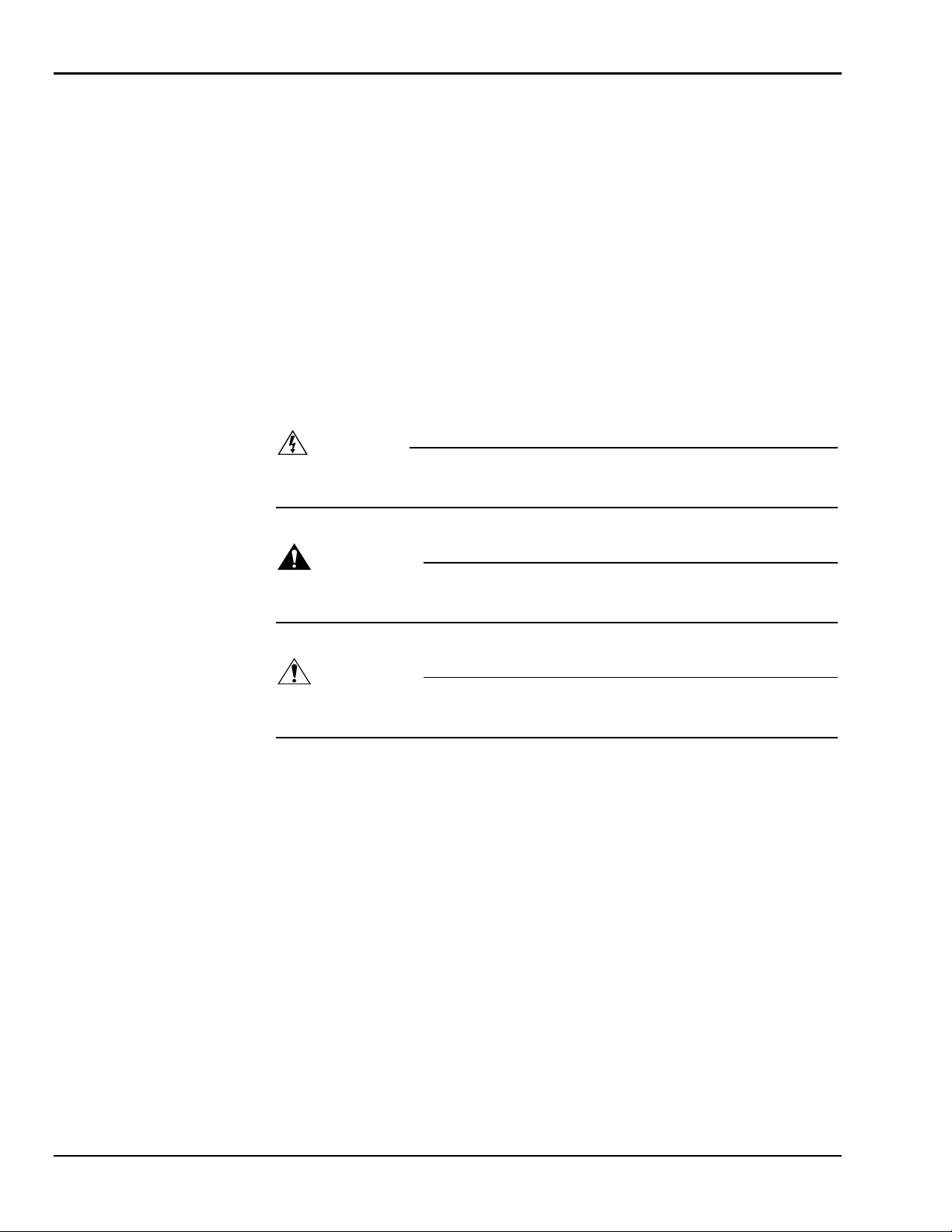
This manual contains DANGERS, WARNINGS, CAUTIONS, and NOTES that must be
followed to prevent the possibility of improper service, damage to the equipment, or personal injury.
DANGER
Dangers warn of equipment operation near electrical power lines that could lead
to personal injury or death.
WARNING
Warnings describe conditions or practices that could lead to personal injury or
death.
CAUTION
Cautions provide information important to prevent errors that could damage machine or components.
NOTE: Notes contain additional information important to a pro cedure.
1-2
Page 9

1 — SAFETY
1-2 BEFORE OPERATION
Ensure the following general safety precautions are followed before operating the
Odyssey 34 lift.
• ALWAYS survey the usage area for potential hazards such as untampered earth
fills, unlevel surfaces, overhead obstructions, and electrically charged conductors
or wires. Be aware of any potential hazards and always consider what could happen. Watch for moving vehicles in the o perating area.
• ALWAYS read, understand, and follow the procedures in this manual before at-
tempting to operate equipment.
• ALWAYS inspect the equipment for damaged or worn parts. Check for cracked
welds, hydraulic leaks, damaged wiring, loose wire connectors, damaged casters,
and damaged outriggers. Also check for any improper operation. NEVER operate equipment if damaged in any way. Improperly operating equipment must be
repaired before using.
• ALWAYS wear proper clothing for the job. Wear protective equipment as re-
quired by federal, state, or local regulations.
• ALWAYS locate, read, and follow all directions and warnings displayed on the
equipment.
• ALWAYS inspect the equipment for any “DO NOT USE” tags placed on the
equipment by maintenance personnel. NEVER use any equipment tagged in this
way until repairs are made and all tags are removed by authorized maintenance
personnel.
• ALWAYS make sure the cage platform and outrigger shoes are free of mud,
grease, or other foreign material. This will reduce the possibility of slipping.
• NEVER allow improperly trained personnel to operate this equipment. Only
trained and authorized personnel shall be allowed to operate this equipment.
• NEVER operate this equipment if you are under the influence of alcohol or
drugs or if you feel ill, dizzy, or unsteady in any way. Operators must be physically fit, thoroughly trained, and no t easily excitable.
• NEVER modify, alter, or change the equipment in any way that would affect its
original design or operation in any way.
• NEVER operate this equipment in ways for which it is not intended.
1-3
Page 10
ODYSSEY 34
1-3 DURING OPERATION
Ensure the following general safety precautions are followed during the operation of the
Odyssey 34 lift.
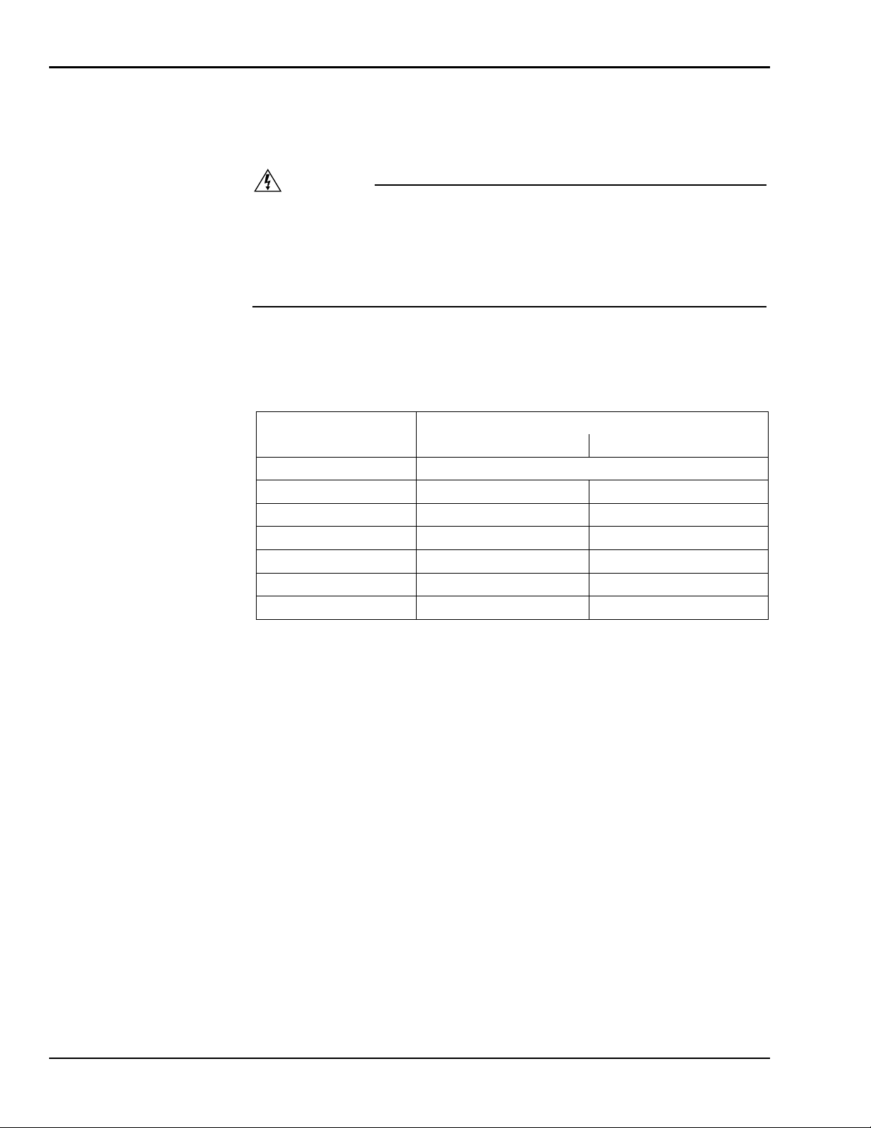
DANGER
This machine is not insulated for use near electrical power lines and DOES NOT
provide protection from contact with or close proximity to any electrically charged
conductor. Operator must maintain safe clearances at all times (10 feet minimum)
and always allow for platform movement such as wind induced sway. Always contact the power company before performing work near power lines. Assume every
line is hot. Remember, power lines can be blown by the wind.
Refer to Table 1-1 for minimum safe approach distances between machine and electrical
power lines.
Table 1-1. Minimum Safe Approach Distances
Voltage Range
(Phase to Phase)
0 to 300V Avoid Contact
Over 300V to 50KV 10 3.05
Over 50KV to 200KV 15 4.60
Over 200KV to 350KV 20 6.10
Over 350KV to 500KV 25 7.62
Over 500KV to 750KV 35 10.67
Over 750KV to 1000KV 45 13.72
Minimum Safe Approach Distance
(Feet) (Meters)
• ALWAYS position lift far enough away from power sources to ensure that no
part of the lift can accidentally reach into an unsafe area.
• ALWAYS operate only on a firm and level surface. NEVER use on surfaces that
do not support the weight of the equipment and its rated load capacity.
• ALWAYS keep yourself and all personnel away from potential pinch or shear
points.
• ALWAYS report any misuse of equipment to the proper authorities. Horseplay is
prohibited.
• ALWAYS maintain good footing on the cage platform. NEVER wear slippery
soled shoes.
• ALWAYS make certain all personnel are clear and there are no obstructions be-
fore repositioning cage platform.
• ALWAYS cordon off area around the outriggers to keep personnel and other
equipment away from it while in use.
• ALWAYS stay clear of wires, cables, and other overhead obstructions.
• ALWAYS disconnect power at the batteries when not in use to guard against un-
authorized use.
1-4
Page 11

1 — SAFETY
• NEVER allow electrode contact with any part of the cage platform if welding is
being performed by a worker from the cage platform.
• NEVER use without the outriggers fully based on the floor.
• NEVER override or by-pass manufacturer's safety devices.
• NEVER release outrigger locks or move unit with a person or materials on
board.
• NEVER stand or sit on cage bars. Work only within the cage platform area and
do not lean out over cage platform to perform work.
• NEVER attempt to increase working height with boxes, ladders, or other means.
• NEVER operate this equipment when exposed to high winds, thunderstorms, ice,
or any other weather conditions that would compromise the safety of the
operator.
• NEVER climb up or down masts.
• NEVER allow ropes, electric cords, hoses, etc. to become entangled in the
equipment when the cage platform is being raised or lowered.
• NEVER exceed manufacturer's load limits.
• NEVER exceed load ratings by transferring loads to cage platform at elevated
heights.
• NEVER use cage to carry materials and never allow overhang of materials when
raising or lowering cage platform.
1-5
Page 12

ODYSSEY 34
1-4 MAINTENANCE SAFETY
Ensure the following general safety precautions are observed when maintenance is performed on the Odyssey 34 lift.
• ALWAYS perform maintenance procedures according to manufacturer's re-
quirements. NEVER short change maintenance procedures.
• ALWAYS check hydraulic system. Make sure all lines, connectors, and fittings
are tight and in good condition.
• ALWAYS keep all mechanisms properly adjusted and lubricated according to
maintenance schedule and manufacturers specifications.
• ALWAYS perform a function check of operating controls before each use and
after repairs have been made.
• ALWAYS locate and protect against possible pinch points prior to performing
maintenance and repairs.
• ALWAYS use only factory approved parts to repair or maintain this equipment.
If this equipment is rebuilt, retesting is required in accordance with factory instructions.
• NEVER add unauthorize d fluids to the hydraulic system or battery. Check manu-
facturers specifications.
• NEVER exceed the manufacturer's recommended relief valve settings.
• NEVER attempt repairs you do not understand. Consult manufacturer if you
have any questions regarding proper maintenance, specific ations, or repa ir.
Battery Maintenance
Ensure the following general safety precautions are followed when battery maintenance is
being performed on the Odyssey 34 lift.
• ALWAYS check battery acid level daily. Check battery test indicator for proper
state of charge on maintenance free batteries before using lift.
• ALWAYS wear safety glasses when working near battery.
• ALWAYS avoid contact with battery acid. Battery acid causes serious burns.
Avoid contact with skin or eyes. If accidental contact occurs, flush with water
and consult a physician immediately.
• ALWAYS disconnect ground cable first when removing battery.
• ALWAYS connect ground cable last when installing battery.
• ALWAYS charge batteries in open, well ventilated areas.
• NEVER smoke when servicing battery.
• NEVER allow batteries to overcharge and boil.
• NEVER short across battery posts to check for current. NEVER break a live cir-
cuit at battery.
• NEVER jump start other vehi cles using lift battery.
1-6
Page 13

1 — SAFETY
1-5 DAMAGED EQUIPMENT POLICY
Safety Statement
At Bil-Jax, we are dedicated to the safety of all users of our products. Therefore, all
Bil-Jax lifts are designed, manufactured and tested to comply with current applicable
Federal OSHA and ANSI codes and regulations.
Damage Policy
There may be occasions when a Bil-Jax lift is involved in an incident that results in structural damage to the lift. This can seriously compromise the ability of the lift to perform in
a safe manner. Therefore, whenever a Bil-Jax lift is damaged structurally or when there is
the possibility of structural damage (this damage may be internal and is not always visible
to the naked eye), Bil-Jax requires that the lift be returned to our facility at 125 Taylor
Parkway, Archbold, Ohio, for reconditioning. If you have any questions concerning what
constitutes structural damage, please call the Bil-Jax Service Department at
419.445.9675.
Damage Repair Notice
There may be occasions when a Bil-Jax lift is involved in an incident resulting in nonstructural damage. When this occurs and repairs are made by the owner or area distributor, please notify Bil-Jax of these non-maintenance repairs and request a repair form to be
filled out and returned to Bil-Jax.
1-7
Page 14

ODYSSEY 34
1-8
Page 15

2
Introduction
2-1 GENERAL DESCRIPTION
The Odyssey 34 lift is designed and manufactured for use as a telescoping personnel lift.
The maximum platform load is limited to 350 lbs. The electric pump motor is powered by
a 12VDC battery. A 20 amp automatic battery charger is included for recharging the battery at the end of each work period.
Platform elevation is accomplished by means of a 2-1/4 inch displacement type hydraulic
cylinder. The lower telescoping section is pushed vertically upward by the cylinder while
the upper sections are raised by a mechanical motion advantage accomplished through
two sets of chains and sheaves. Platform elevation and descent is controlled by pushbuttons on the main control box located on the back of the machine, or the transmitter
mounted on the cage platform.
Safety of operation is assured by proper inspection and maintenance procedures as set
forth in this manual. The possibility of platform free-fall is eliminated by proper maintenance and replacement of the chains, sheaves and sheave pins, a properly installed flow
restrictor valve, and a clean mast. The adjustable restrictor valve controls and fixes the
rate of platform descent whether empty or fully loaded to approximately 0.6 feet per second. A hydraulic hose failure will result in the same rate of descent, eliminating free-fall,
when the restrictor valve is installed properly.
Emergency lowering of the platform is accomplished by means of a manual control valve
located on the pump/motor unit.
The Odyssey 34 lift features a displacement type of cylinder that will not rust or corrode
during storage since the cylinder rod is immersed in oil. It is important that the cylinder
rod be kept clean and undamaged for the protection of the cylinder head packing.
The outrigger lock safety switches prevent the Odyssey 34 from raising until the four outriggers have been properly positioned and engaged. This helps to make the Odyssey 34
lift a safe, dependable machine.
Carefully read all the safety instructions contained in Section 1 of this manual before operating the Odyssey 34 lift.
2-1
Page 16

ODYSSEY 34
2-2 SPECIFICATIONS
Odyssey Lift Electric Hydraulic Lift Platform
Model Number Odyssey 34 Serial Number ________________
Manufactured by: Bil-Jax, Inc.
125 Taylor Parkway
Archbold, Ohio 43502
419.445.8915
Table 2-1. Specifications
Rated Platform Load 350 lbs (158.8 kg) total including operator
Extended Platform Height 34 ft (10.36 m)
Retracted Platform Height 6 in. (15 cm)
Platform Dimensions 28 in. x 30 in. (71 cm x 76 cm)
Base Dimensions
(Outriggers Extended)
Retracted Dimensions 29 in. wide x 74 i n. long x 79 in. high
Gross Shipping Weight 1350 lbs (614 kg)
Full Extension Time 45 seconds empty, 50 seconds loaded
Complete Retraction Time 55 seconds empty, 45 seconds loaded
Platform Extension Rate 0.86 ft/sec (0.26 m/sec) empty
Hydraulic System Pressure 1200 psi empty, 2000 psi loaded
Power Source DC - 12 volt deep cycle battery
66 in. x 72 in. (168 cm x 183 cm)
(74 cm wide x 190 cm long x 201 cm high)
0.59 ft/sec (0.18 m/sec) loaded
2-3 WARRANTY
Bil-Jax warrants its telescopic lifts for one year from the date of delivery against all defects of material and workmanship, provided the unit is operated and maintained in compliance with Bil-Jax’s operating and maintenance instructions; structural components are
warranted for three years. Bil-Jax will, at its option, repair or replace any unit or component part which fails to function prop erly in normal use.
This warranty does not apply if the lift and/or its component parts have been altered,
changed, or repaired without the consent of Bil-Jax or by anyone other than Bil-Jax or its
factory trained personnel, nor if the lift and/or its components have been subjected to
misuse, negligence, accident or any conditions deemed other than those considered as occurring during normal use.
Components not manufactured by Bil-Jax are covered by their respective manufacturers
warranties. A list of those components and their warranties is available upon written request to Bil-Jax.
Bil-Jax shall not in any event be liable for the cost of any special, indirect or consequential damages to anyone, product, or thing. This warranty is in lieu of all other warranties
expressed or implied. We neither assume nor authorize any representative, or other person, to assume for us any other liability in connection with the sale, rental, or use of this
product.
2-2
Page 17
3
Operation
3-1 OPERATOR CONTROLS
The Odyssey 34 lift is equipped with several operator controls; a transmitter mounted in
the cage platform to control the lift; a receiver mounted on the base to monitor and control the lift; an
the lift before raising the platform.
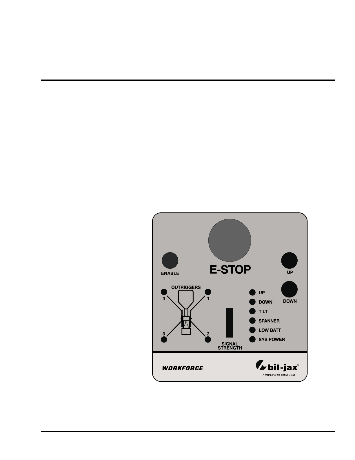
Receiver
The receiver is located on the back of the base frame and contains four controls, UP and
DOWN pushbuttons, an ENABLE pushbutton, and an EMERGENCY STOP pushbutton. The re-
ceiver also contains LEDs to monitor the operation of the lift and a signal strength indicator to monitor the strength of the signal being sent from the platform transmitter. While
the operator normally does not raise or lower the lift from the receiver, the receiver does
control the operation of the Odyssey 34 lift. When the operator pushes a pushbutton on
the platform transmitter, the transmitter sends a signal to the receiver, the receiver processes that signal and controls the various lift functions. Refer to Figure 3-1.
ON/OFF switch to turn power on or off; and a laser pointer to help position
Figure 3-1. Receiver
3-1
Page 18
ODYSSEY 34
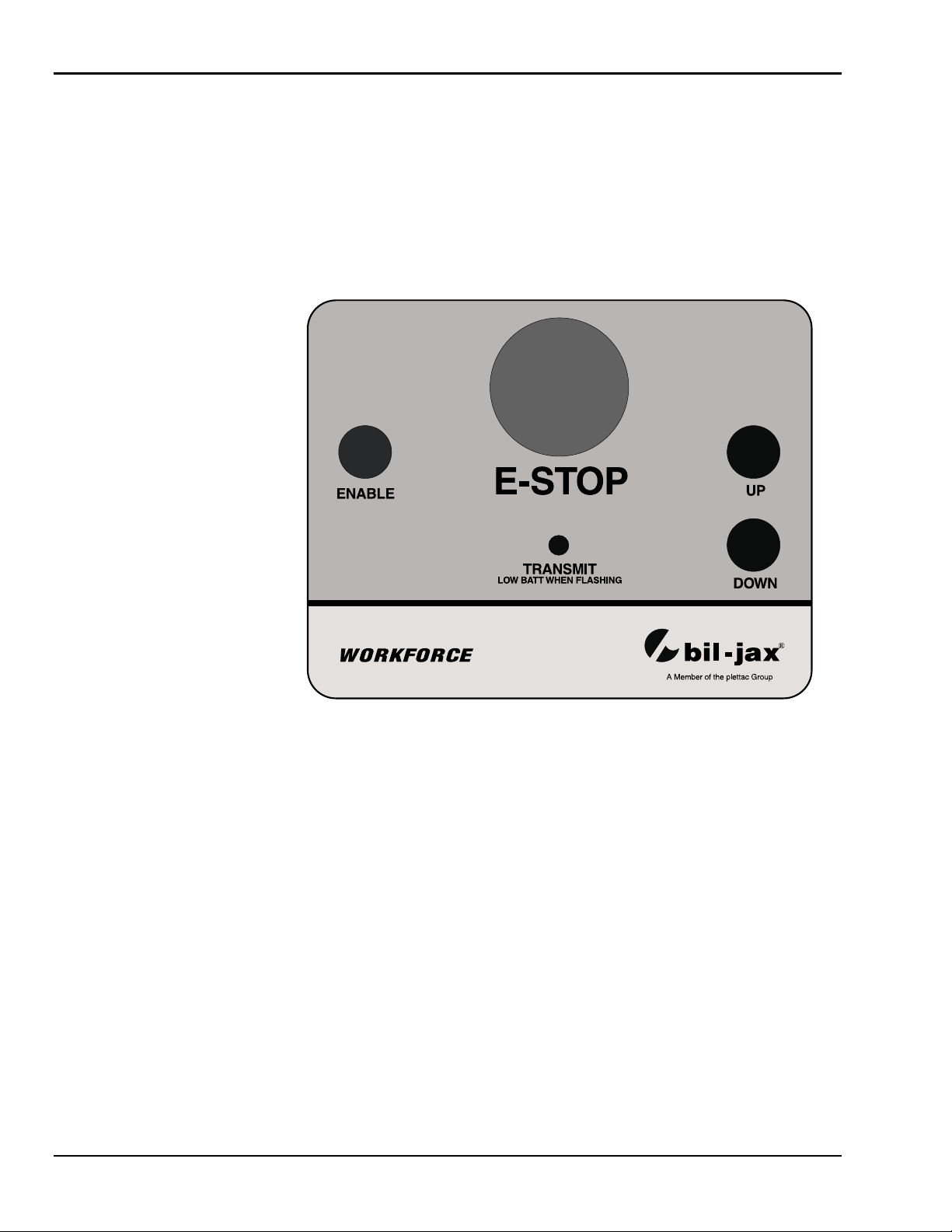
Transmitter
The transmitter is located on the mast directly above the platform. The transmitter contains four controls,
EMERGENCY STOP pushbutton. The controls on the upper control box are used to raise and
lower the unit. There are no electrical connections between the transmitter and the receiver, or between the transmitter and the lift power supply. The transmitter operates from
a 9-Volt battery installed in the transmitter control box. An LED monitors operation of
the transmitter — a flashing LED indicates a low battery. The battery should be replaced
with a new battery when the LED flashes. The LED will light with a steady glow when
any control is activated and a signal is being sent to the receiver. Refer to Figure 3-2.
UP and DOWN pushbuttons, an ENABLE pushbutton, and an
Figure 3-2. Transmitter
3-2
Page 19
3 — OPERATION
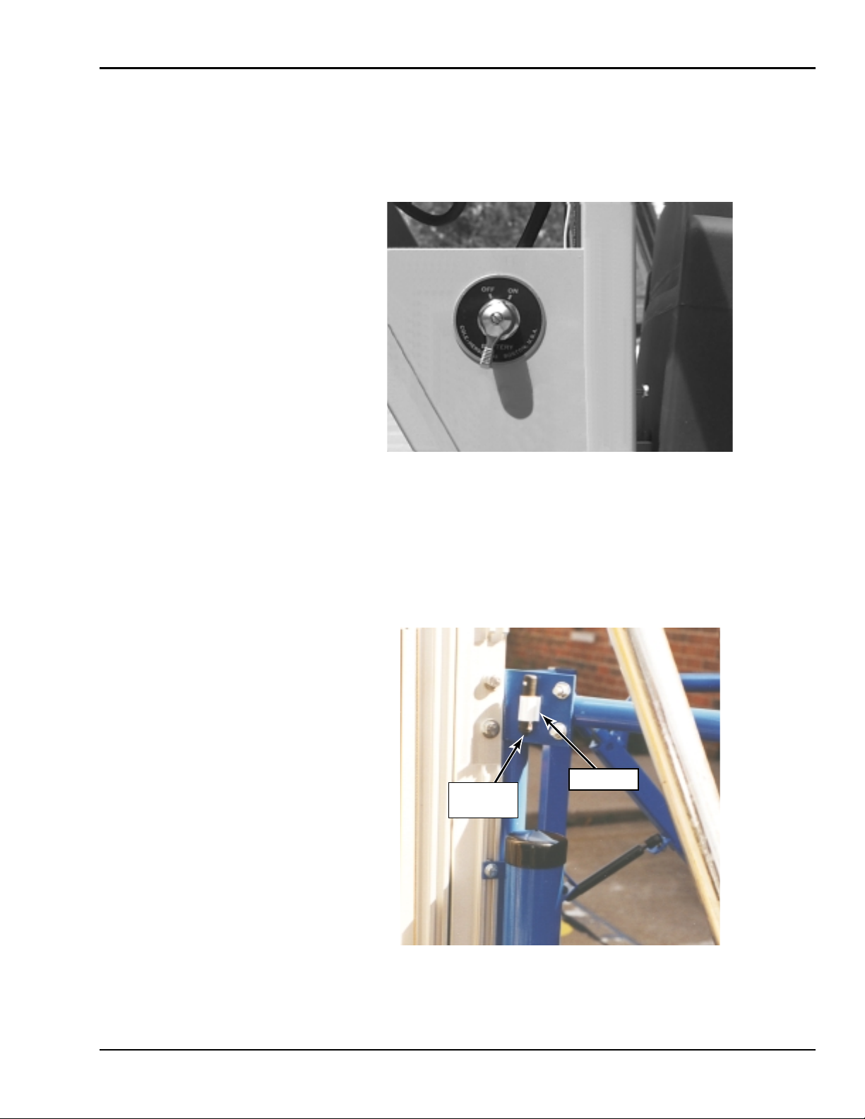
ON/OFF Switch
The ON/OFF switch is used to turn the battery power on or off to the lift. Turning the
switch to the
To conserve battery power, the switch should be in the
being used. Refer to Figure 3-3.
ON position activates the Audio Program ‘Hal’ and turns power on to the lift.
OFF position when the lift is not
Figure 3-3. ON/OFF Switch
Laser Pointer
The laser pointer is used to help position the lift before it is raised. It is mounted on the
side of the cage. To help position the lift before setting outriggers, turn the laser pointer
ON and place it in its holder in an upright position. When the red dot from laser pointer is
in the area where you want to work, this is the position you want the Odyssey 34 lift to be
located before setting the outriggers. Refer to Figure 3-4.
LASER
POINTER
HOLDER
Figure 3-4. Laser Pointer
3-3
Page 20
ODYSSEY 34
3-2 NORMAL OPERATING PROCEDURE
Perform the following procedures to operate the Odyssey 34 lift.
1. Read and follow all safety precautions contained in Section 1 and all responsibilities outlined in the ANSI A92.3 reprint contained in Section 7 of this manual.
2. Position the lift at the work area. Make sure the lift is on a firm and level surface
and that there are no potential hazards such as overhead obstructions or electrically charged conductors. Do not operate the lift if such hazards exist.
3. Check the lift for damaged or worn parts and repair or replace as necessary.
4. Check to be sure that the cage platform is properly attached to the lift.
5. Pull the four outriggers away from the base. The spring-loaded pin on the jack
should lock in place. If the spring-loaded pin does not lock in, unwind the jack
until the pin snaps in place. Adjust each outrigger so that its footpad is firmly set.
For best performance, assure that the wheels are off the ground.
6. Turn the
ON/OFF switch to ON. Ensure that the E-STOP pushbutton is not enga ged.
The controller’s audio program ‘Hal’ will start. Hal will instruct you how to proceed. Hal will tell you the lift is ready to operate or what outrigger needs to be
adjusted; the corresponding LED will also be lit.
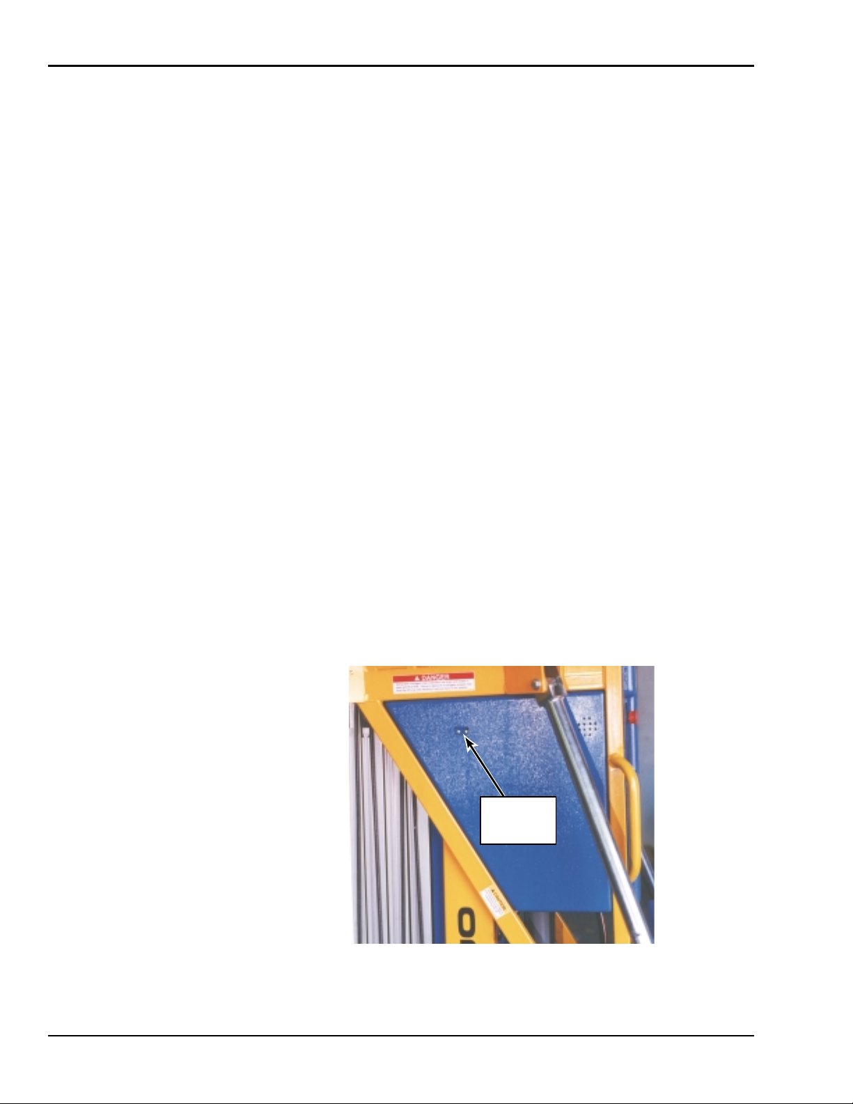
7. Adjust the outriggers until all LEDs are lit. When all outriggers are set properly
and the unit is level, Hal will tell you the lift is ready to operate and the tilt LED
will be off. To enable you to monitor the setting of the outriggers, LEDs for the
corresponding outriggers are located on the sides of the main frame, Figure 3-5.
When the outriggers are set properly the LEDs will be ON.
NOTE: The lift is equipped with a level sensor that will prevent the lift from rais-
ing if the lift is at a slope greater than 1.5 degree. The TILT LED on the
receiver will light and the audio program will tell you that the lift is not
level. Adjust the outriggers until the lift is level and the TILT LED is
OFF.
MAST
MOUNTED
LEDs
Figure 3-5. Outrigger LEDs on Main Frame
3-4
Page 21
3 — OPERATION
8. Enter the cage platform. Ensure that the cage gate is closed and engaged properly. A proximity switch in the gate will prevent operation of the lift if the gate is
not properly closed.
9. The lift is now ready for operation. While depressing the
lect the
lower respectively. The
UP or DOWN pushbutton on the transmitter. The platform will raise or
EMERGENCY STOP pushbutton deactivates the control
ENABLE pushbutton, se-
circuit.
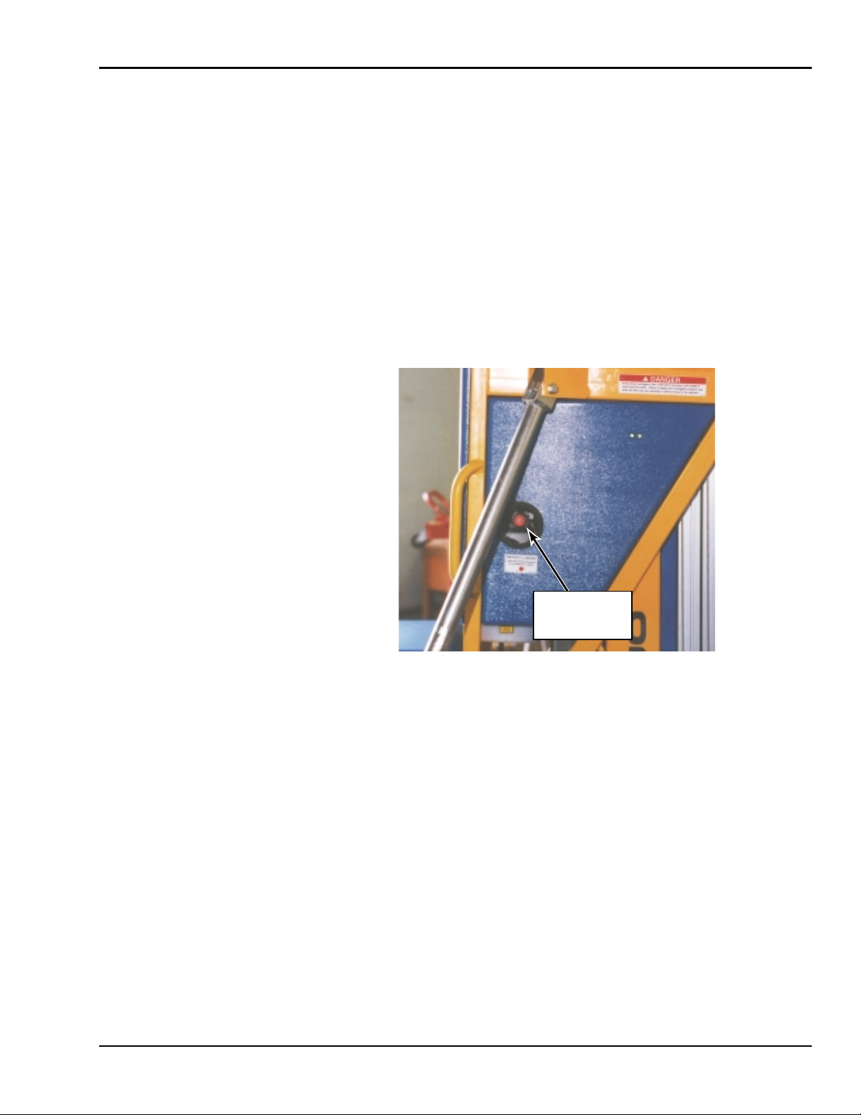
3-3 EMERGENCY LOWERI NG PROCEDURE
The Odyssey 34 lift is equipped with a manual lowering valve in case of emergency situations to lower the platform. The emergency lowering valve is located on the hydraulic
pump. The valve may be accessed through the opening on the side of the machine. To
lower the platform, turn the red knob on the valve counterclockwise. Refer to Figure 3-6.
EMERGENCY
LOWERING
VALVE
Figure 3-6. Emergency Lowering Valve
3-5
Page 22

ODYSSEY 34
3-6
Page 23
4
Maintenance
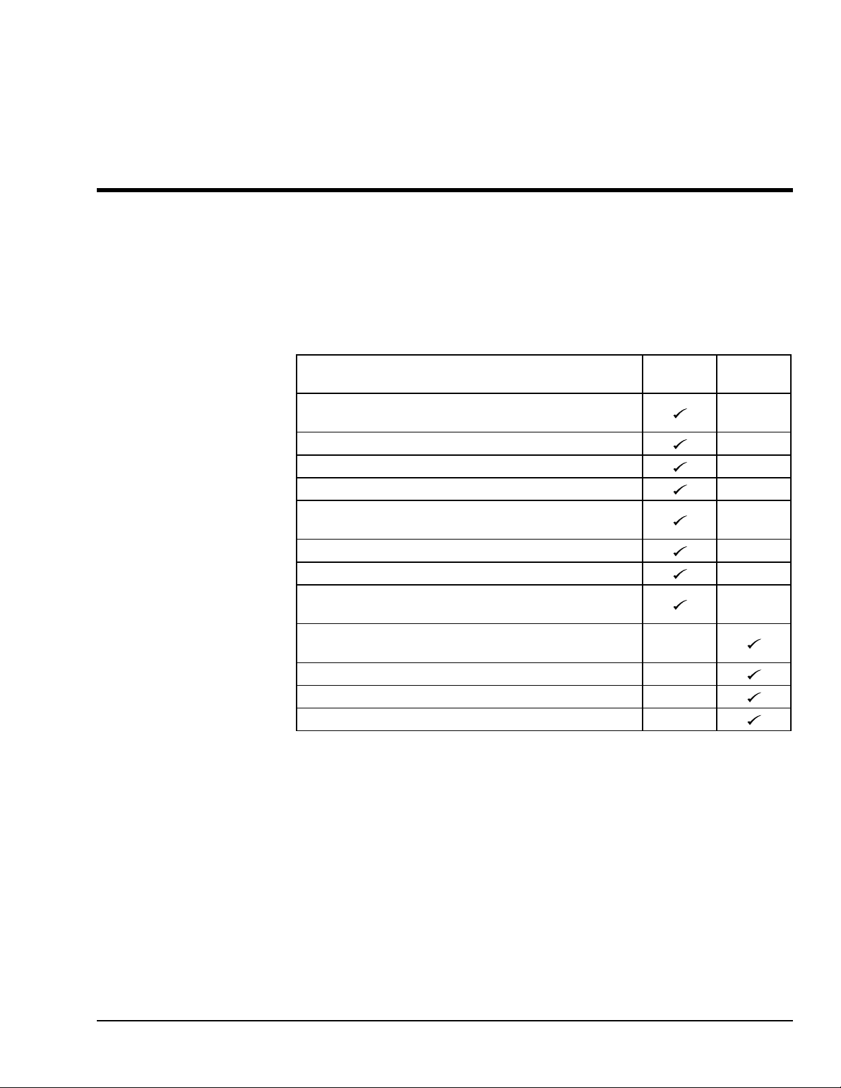
4-1 SCHEDULED SERVICE CHECKS
Daily/Weekly Service Checks
Perform the following daily/weekly service checks as listed in Table 4-1.
Check chain assemblies for split leaves, loose pins,
excessive wear, or elongation.
Check battery electrolyte level.
Check and retighten all nuts and bolts.
Check cage gate is secure.
Check to be sure slide blocks and their path are clean and
lightly lubricated with a silicone lubricant.
Check level sensor.
Check to see that all decals are present.
Check that all functions on transmitter and receiver are
operating properly.
Check for wear on chain sheaves, sheave axles, and
bearings.
Lubricate chains with 40W oil.
Check wheels for wear on axles.
Check surface of casters for cracks or excessive wear.
Table 4-1. Daily/Weekly Service Checks
Service Check
before use Weekly
Daily
4-1
Page 24

ODYSSEY 34
Monthly Service Checks
Perform the following monthly service checks as listed in Table 4-2.
Table 4-2. Monthly Service Checks
Service Check
Clean battery terminals.
Check operation of manual
emergency lowering valve.
Lubricate wheels and axles.
Lubricate steel mast with dry
silicone spray.
Every
month
Every
6 months
Every
12 months
Check battery cables and wiring
for loose connections and
damaged wires.
Replace hydraulic oil.
Check slide blocks for wear.
Check for mast sway.
Load test with 350 pounds.
Replace lift chains.
Every
48 months
4-2
Page 25
4 — MAINTENANCE
4-2 LUBRICATION
Lubrication makes operation of the Odyssey 34 lift more efficient and extends the life of
the unit. Perform the following lubrication procedures.
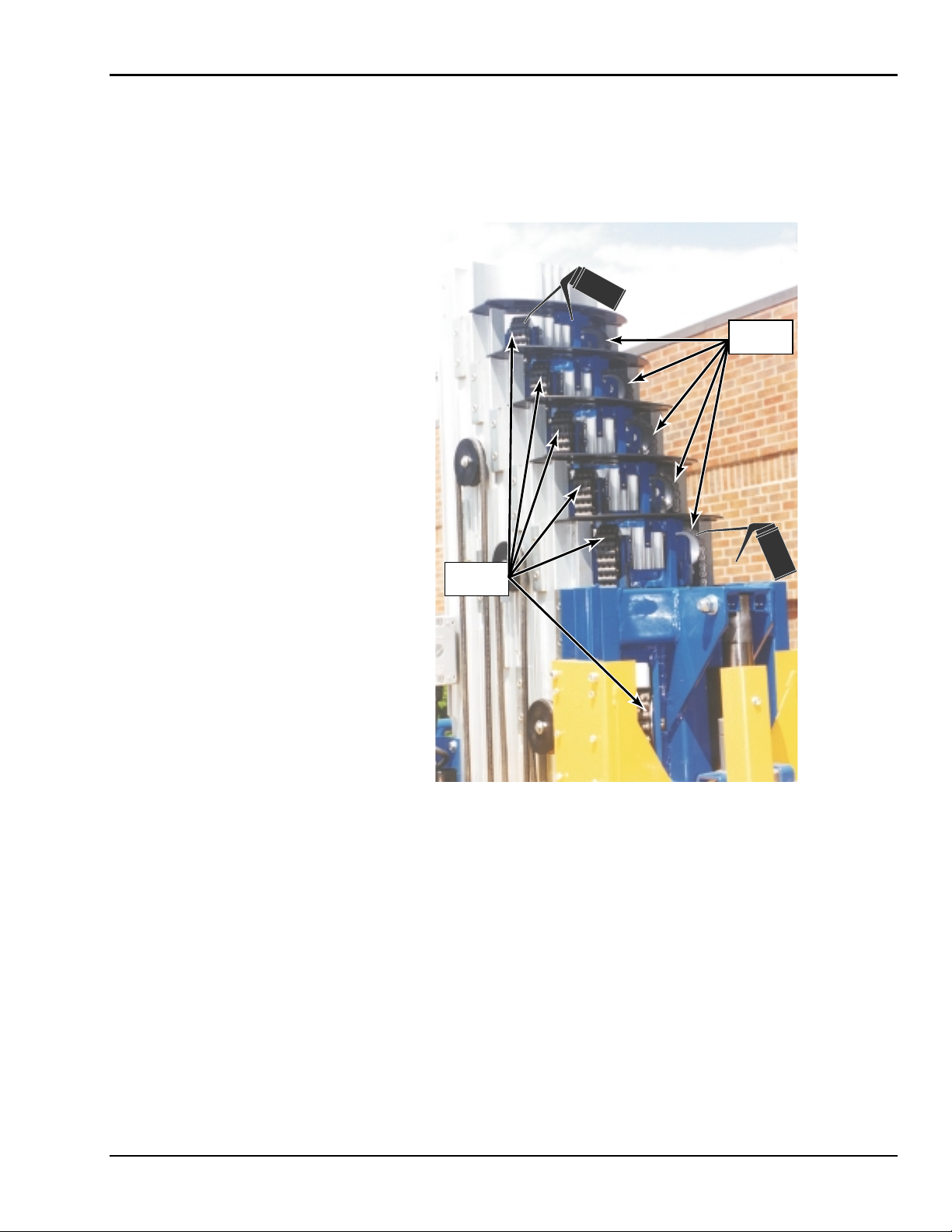
1. Oil lift chains with clean 40W oil weekly or as needed. Refer to Figure 4-1.
LIFT
CHAINS
LIFT
CHAINS
Figure 4-1. Lift Chain Lubrication
4-3
Page 26

ODYSSEY 34
2. Grease both wheels and axles at the grease fittings on each wheel semiannually
with wheel bearing grease. Refer to Figure 4-2.
Figure 4-2. Wheel and Axle Lubrication
3. Lubricate the steel mast slides with dry silicone spray semiannually. Apply a
light spray coating to the slide surfaces as shown in Figure 4-3.
Figure 4-3. Steel Mast Slide Lubrication
NOTE: The plastic slide blocks in the mast are made of a bearing material which
has a high degree of lubricity and need only be kept clean. However,
precautions should be taken to ensure that the paths along which the
blocks move are kept clean and lightly lubricated with a dry type silicon
lubricant.
4-4
Page 27

4 — MAINTENANCE
4-3 HYDRAULIC SYSTEM
Hydraulic system maintenance varies by the amount of use and the environment in which
the lift is used. Constant attention to keep the oil clean and the reservoir properly filled
will help prevent possible damage to the system.
Hydraulic System Inspection
Check the hydraulic hose and fittings for leaks and damage daily. Tighten or replace as
necessary to prevent hydraulic oil loss. Refer to the hydraulic schematic diagram in Section 6 for general reference.
Fluid Check and Replacement
The reservoir should be filled to within 1/2 inch of the top with the platform in its lowest
position. The lift is shipped from the factory with Energol HLP-HD46 (BP Oil), a high
grade, non-foaming hydraulic oil designed for temperatures as low as -20°F/-29°C. Use
Dextron Automatic Transmission Fluid Type A for temperatures as low as -40°F/-40°C.
If either oil is not available, a good grade SAE 10W hydraulic oil may be used where the
minimum climatic temperature is above 32°F/0°C. SAE 5W hydraulic oil may be used
where temperatures are as low as 0°F/-18°C. Do not mix different hydraulic oils. Clean
the reservoir sump strainer and replace the hydraulic oil at least once a year or whenever
it becomes contaminated.
Hydraulic System Air Bleeding Procedure
Delayed response or sporadic action in the unit may indicate a presence of air in the cylinder. Perform the following procedure to bleed air from the system.
1. Fill the reservoir with the proper hydraulic fluid.
2. Fully extend the lift.
3. Lower the unit to allow the oil with entrapped air to return to the reservoir, being
careful not to overflow it.
4. Let the unit set while the air escapes the fluid and then repeat if necessary. Each
time the platform is lowered, refill the reservoir to prevent pumping more air into
the cylinder.
4-5
Page 28

ODYSSEY 34
Pressure Relief Valve Reset
Perform the following procedure to reset the pressure relief valve. Refer to Figure 4-4.
1. Disconnect the hydraulic hose from the main pressure port.
2. Install a 4000 psi gage into the main pressure port in the pump unit.
CAUTION
Do not adjust the pressure relief valve higher than 2300 psi. Overloading may
occur at pressures greater than 2300 psi.
3. Remove the hex cover from the pressure relief valve.
4. While depressing the
the screw until maximum pressure of 2300 psi is obtained.
5. After adjusting the pressure relief valve, replace the hex cover, remove the 4000
psi gage, and reconnect the hydraulic hose to the main pressure port.
6. If a gage is unavailable, place 400 pounds on the platform and adjust the pressure relief valve screw so that the load can just be lifted without bypassing oil
through the pressure relief valve.
ENABLE and UP pushbutton on the lower control box, adjust
RELIEF VALVE
(LOCATED OPPOSITE
OF EMERGENCY
LOWERING VALVE)
MAIN
EMERGENCY
LOWERING
VALVE
PRESSURE
PORT
Figure 4-4. Pressure Relief Valve Adjustment
4-6
Page 29

4 — MAINTENANCE
Down Valve Operation Check and Adjustment
The adjustable down valve (13, Figure 4-5) is located in the base of the hydraulic cylinder. When properly adjusted, the down valve will allow the cylinder to fully retract in 35
to 39 seconds.
Adjust the down valve with the cylinder fully retracted. Loosen the lock nut and turn the
adjusting screw in to extend the retract time and out to shorten the retract time. Extend the
cylinder and note the time it takes to retract. Adjust as necessary to extend or shorten the
retract time. When the cylinder is retracting properly, hold the adjusting screw and tighten
the lock nut.
Hydraulic Cylinder Repair
CAUTION
Removing the hydraulic cylinder from the Odyssey Lift requires major disassembly of the unit. Contact Bil-Jax for assistance before removing the hydraulic cylinder from the unit.
Hydraulic Cylinder Removal
It is recommended that Bil-Jax be contacted for assistance before removing the hydraulic
cylinder.
WARNING
Keep hands and feet away from elevated masts at all times.
1. Raise lift far enough to place scrap 4 x 4 wood block(s) under the main (welded)
mast. Lower lift down onto the block(s) and turn off the main power.
2. Remove mounting bol t (10), washers (9), and nut (8) securing the top of the hydraulic cylinder rod to the main (welded) mast.
3. Open the emergency lowering valve (See Figure 3-6) and use a pry bar to lower
the cylinder rod down from the main (welded) mast connection.
4. Be sure cylinder is retracted and pressure is released from the system. Place a
pan underneath the hydraulic cylinder to catch the hydraulic oil.
5. Disconnect the hydraulic hose from the bottom of the cylinder and drain the remaining hydraulic oil.
6. Remove four bolts (2, Figure 6-3), lock washes (3), and two cylinder brackets
(4) securing cylinder (7) to the base. Lift the cylinder to remove it from the
mounts on the base unit.
7. After maintenance has been performed on the hydraulic cylinder, reinstall the
cylinder in the mounts on the base unit, reconnect the hydraulic hose, and close
the emergency lowering valve. Turn on the main power, raise the lift until the
cylinder rod slides back into the main (welded) mast connection, and reinstall the
mounting bolt, washers, and nut.
Hydraulic Cylinder Repair Procedure
Perform the following procedure to repair and maintain the hydraulic lift cylinder. Refer
to Figure 4-5. It is recommend that whenever the hydraulic cylinder is disassembled that
all seals be replaced; order seal kit B02-13-0099.
4-7
Page 30

ODYSSEY 34
Disassemble and inspect the hydraulic cylinder as follows:
1. Remove retaining ring (14, Figure 4-5) by rotating cylinder head (5) clockwise
until the edge of the retaining ring appears in the milled opening of cylinder tube
(12).
2. Pull cylinder head (5) assembly off the end of cylinder rod (1) and from cylinder
tube (12).
3. Pull assembled cylinder rod (1) and piston (8) from the cylinder tube.
4. Remove piston nut (11) and remove piston (8) assembly from the end of the rod.
5. Remove wiper (3), u-cup seal (4), static o-ring (7), and back-up ring (6) from
cylinder head (5). Discard all parts.
6. Remove u-cup seals (9 and 10) from piston (8). Discard the u-cup seals.
7. Inspect rod (1) for any scratches or pits. Pits that go into the base metal are unacceptable. Scratches that catch the fingernail, but are not through the base metal
or less than 1/2 inch long and are around the rod, are acceptable providing they
are not sharp enough to cut the seal. The rod surface should not have any of the
chrome worn through. Replace the rod if any of these conditions are not met.
8. Inspect cylinder head (5). Check the inside bore of the cylinder head for
scratches; deep scratches are unacceptable. Check the bore for polishing —
polishing indicates uneven loading. The bore should be checked for out-ofroundness; if the bore is more than 0.007 inch out-of-round, the head should be
replaced. Damage to any of the seal grooves is unacceptable. Replace the head if
any of these conditions are not met.
9. Inspect piston (8). Check the outside surface of piston for scratches; deep
scratches are unacceptable. Check the outside surface for polishing. If polishing
is noticed, the piston should be checked for out-of-roundness. If out-of roundness exceeds 0.007 inch, the piston should be replaced. Damage to any of the
seal grooves is unacceptable. Replace the piston if any of these conditions are
not met.
10. Inspect cylinder tube (12) for any scratches or pits. Pits or scratches that are
deep enough to catch the fingernail are not acceptable. Scratches that catch the
fingernail, but are less than 1/2 inch long and are around the tube, are acceptable
providing they are not sharp enough to cut the seal. Replace the cylinder tub e if
any of these conditions are not met.
Assemble the hydraulic cylinder as follows:
11. Lubricate piston (8) and u-cup seals (9 and 10) with hydraulic fluid.
12. Stretch u-cup seals (9 and 10) into the grooves. The sealing lips of the u-cup
seals should face toward the outside face of the piston. Be careful to avoid damaging the seal grooves during installation; scratching the grooves may cause bypass leakage. Allow the assembled piston to sit 1 hour to allow the seals to return
to shape.
13. Lubricate cylinder head (5), wiper (3), u-cup seal (4), static back-up ring (6), and
static o-ring (7) with hydraulic fluid.
14. Twist dual lip u-cup seal (4) into a ‘C’ shape and allow it to snap into the lower
groove.
15. Twist wiper (3) into a ‘C’ shape and allow it to snap into the outer groove.
4-8
Page 31

4 — MAINTENANCE
16. Install static back-up ring (6) and static o-ring (7) into the static seal groove in
the head. Make sure the back-up ring is installed closest to the retaining ring
groove. Allow the assembled head to sit 1 hour to allow the seals to return to
shape.
17. Thoroughly rinse the inside of cylinder tube (12) with a high-pressure rinse and
wipe with a lint free cloth.
18. Install the head assembly followed by the piston assembly onto the rod. Torque
piston nut (11) to 100-120 ft. lbs.
1.
B02-13-0099 Seal Kit
includes 2, 3, 4, 6, 7,
9, 10, and 14.
2.
B02-03-0019 is the
Complete Cylinder
Assembly.
Rod, Cylinder
1.
O-Ring
2.
Wiper
3.
Seal, U-Cup
4.
Head, Cylinder
5.
Static Back-Up Ring
6.
Static O-Ring
7.
Piston
8.
Seal, U-Cup
9.
Seal, U-Cup
10.
Nut, Piston
11.
Tube, Cylinder
12.
Valve, Adjustable Down
13.
Ring, Retaining
14.
14
NOTE:
1
2
3
4
(B02-14-0040)
(B02-13-0100)
5
12
6
7
8
(B02-13-0101)
9
10
13
11
Figure 4-5. Hydraulic Cylinder Exploded View
19. Apply anti-seize to the head outer surface, especially static o-ring (7).
20. Coat the entire rod assembly with hydraulic fluid and insert the rod into the cylinder tube. When inserting cylinder head (5), make sure that static o-ring (7)
does not extrude into the retaining ring slot in the cylinder tube. Be careful not to
nick the seals as they enter the cylinder tube.
21. Rotate the cylinder he a d until the retaining ring hole is visible through the slot
milled into the tube. Insert retaining ring (14) hook into the hole and rotate the
head 1-1/4 turns until the retaining ring is completely pulled into the cylinder
tube and the ends are covered.
22. Reinstall the hydraulic cylinder into the unit and reconnect the hydraulic hose.
Refill hydraulic fluid reservoir.
23. Pressurize the cylinder and extend one full stroke to fill it with hydraulic fluid
and remove any trapped air.
4-9
Page 32

ODYSSEY 34
4-4 ELECTRICAL SYSTEM
Regular maintenance is necessary to keep the electrical system in proper working order.
Check daily all electrical wires for cuts, broken wires, potential short circuits, and any
other damage.
Battery Care and Charging
The electric system is designed to provide power for a normal work shift. However, the
charge life of the battery pack depends on machine usage. Plan your work to prevent unnecessary use of electrical power.
Since the power source for the machine is a battery, proper battery care is important. Recharge the battery after each work shift. When the machine is not being used, batteries
should be charged at least once a week. Normal battery charging time should be 10 to 12
hours. If the battery is extremely low, charging time may be as long as 24 hours.
Clean battery terminals monthly. Remove the cables from the battery, clean the battery
posts and cable ends to shiny metal, and replace. Always connect the insulated cable from
the starter solenoid to the positive post. Lubricate the outside of the connections with petroleum jelly or grease.
Battery Charging Procedure
1. Connect an extension cord from a 110V AC 60 Hz outlet to the flush mount receptacle on the side of the Odyssey Lift. The extension cord should be kept as
short and as large as possible to reduce voltage drop.
2. When there is power to the battery charger the ammeter will display the rate of
charge.
CAUTION
Before making or breaking connections between charger and battery, always remove the power cord from the 110 volt AC outlet. Always check the battery electrolyte level and add water after charging the battery. For more information, refer
to the instructions supplied with the battery charger.
3. Unplug the extension cord from the flush mount receptacle on the side of the
Odyssey Lift.
4-10
Page 33

4 — MAINTENANCE
4-5 LIFT CHAINS AND SLIDE BLOCKS
WARNING
Do not operate a unit on which any chain assembly is damaged or in need of replacement. Operating a unit with a damaged chain can cause severe injury or
death to personnel and damage to equipment.
Inspect all lift chains daily. Inspect for signs of wear, split leaves, loose pins, clevis damage, and elongation. Replace any chain which is damaged in any way. Chain assemblies
may be ordered from your dealer or direct from the factory. Do not operate a unit on
which any chain assembly is damaged and in need of replacement.
Chain Elongation Inspection
First Mast Chain (BL-566 Chain)
One pitch of chain should measure 5/8 in. (1,5875 cm). Measure 20 pitches of chain. The
ideal measurement for 20 pitches of chain should be 12.5 in. (31,75 cm). Replace the
chain if 20 pitches measure over 12.75 in. (32,385 cm). Refer to Figure 4-6.
NOTE: It is recommended that
chains be replaced every four
years unless damage or wear
requires replacement at a lesser
interval.
Figure 4-6. BL-566 Chain Elongation Inspection
Second through Sixth Mast Chain (BL-466 Chain)
One pitch of chain should measure 1/2 in. (1,2700 cm). Measure 20 pitches of chain. The
ideal measurement for 20 pitches of chain should be 10.0 in. (25,40 cm). Replace the
chain if 20 pitches measure over 10.25 in. (26,035 cm). Refer to Figure 4-7.
Figure 4-7. BL-466 Chain Elongation Inspection
4-11
Page 34

ODYSSEY 34
Lift Chain Adjustment
1. Raise the platform to the maximum extended height and then lower it while
someone checks to see that all sheaves are turning, and checks for chain damage
or wear.
2. Chains should be tight to the touch with no loose play. Check all lift chains for
snugness. If a chain is loose, it will need to be adjusted.
3. After the platform is completely lowered, raise the complete Odyssey 34 lift with
a fork lift. Insert the forks into the fork lift openings in the base from the lower
control box end.
4. Loosen lock nut (48, Figure 6-1) attaching clevis pin (50) to lifting bar (47).
Tighten hex nut (49) until the chain just becomes snug. Do not overtighten any
chain so that the mast is raised from its resting position.
5. Make sure lock nuts (48) are turned onto the threaded clevis ends with at least
1/8 in. of the clevis end extending through the nut. Replace any lock nut which
does not stay in position during use.
4-12
Page 35

4 — MAINTENANCE
Slide Block Adjustment
Annually check for wear on the slide blocks and replace or retighten as necessary. If the
lift exhibits excessive mast sway, it is probable that the slide blocks need adjustment. The
slide blocks should be adjusted so that there is no air gap between the slide block and the
mast the slide block is moving against. There are 4 adjustable slide blocks. The adjustment procedure is the same for all slide blocks. Refer to Figure 4-8.
1. Loosen, do not remove, the slotted hex head screw securing the slide block to be
adjusted.
2. Using an allen wrench, turn the set screws in (clockwise). This will push the
block in against the mast. Do not overtighten. Tighten the slotted hex head screw
to secure the slide block in position.
3. Check all slide blocks and make adjustments as necessary.
4. After all adjustments are made, fully extend the lift. If the platform can be lowered without stopping then the blocks are properly adjusted.
SLIDE
BLOCKS
SET
SCREW
SLOTTED
HEX HEAD
SCREW
Figure 4-8. Slide Block Adjustment
NOTE: The plastic slide blocks in the mast are made of a bearing material which
has a high degree of lubricity and need only be kept clean. However,
precautions should be taken to ensure that the paths along which the
blocks move are kept clean and lightly lubricated with a dry type silicon
lubricant.
4-13
Page 36

ODYSSEY 34
Guide Peg Adjustment
Annually check for wear on guide pegs (9, Figure 6-1 and 1, Figure 6-2) and replace or
retighten as necessary. If any of the masts exhibit excessive side sway, it is probable that
the guide pegs need adjustment. The guide pegs should be adjusted so that there is no air
gap between the guide peg and the mast. There are 8 adjustable guide pegs per aluminum
mast and 12 adjustable guide pegs on the steel mast. The adjustment procedure is the
same for all guide pegs. Refer to Figure 4 -9.
1. Using an allen wrench, turn the set screws in (clockwise). This will push the
guide peg in against the mast. Do not overti ght en.
2. Check all guide pegs and make adjustments as necessary.
3. After all adjustments are made, fully extend the lift. If the platform can be lowered without stopping, then the guide pegs are properly adjusted.
ALUMINUM
MAST
STEEL
MAST
SET
SCREWS
Figure 4-9. Guide Peg Adjustment
NOTE: The plastic guide pegs in the mast are made of a bearing material which
has a high degree of lubricity and need only be kept clean. However,
precautions should be taken to ensure that the paths along which the
guide pegs move are kept clean and lightly lubricated with a dry type
silicon lubricant.
4-14
Page 37

4 — MAINTENANCE
4-6 TROUBLESHOOTING
Table 4-3. Troubleshooting Chart
Problem Cause Correction
1. Control panel LEDs will not
light and audio program
‘Hal’ will not respond.
2. Control Panel LEDs will not
turn off.
3. When UP switch is selected,
motor runs but unit will not
lift a load.
4. Masts have excessive sway
when fully extended.
a. Low voltage*.
b. Master power switch turned off.
c. Emergency stop button is activated
(pushed in).
d. Burned out LED.
e. Two parts of battery connector plug
not mated together.
a. Lift is out of level.
b. Broken or loose wire.
a. More than 350 lbs. on platform.
b. NO (Normally Open) valve is not
being energized.
c. Emergency lowering valve is open.
d. Mast sections are dirty.
a. Plastic slide blocks are out of adjus-
ment.
b. Plastic guide pegs are out of adjust-
ment.
a. Recharge battery or replace if dam-
aged.
b. Turn on master power switch.
c. Pull out on emergency stop button.
d. Replace LED board.
e. Mate battery connector plug parts
together.
a. Level lift with outrigger jacks or
relocate lift to level surface.
b. Repair or replace wire.
a. Ensure load is 350 lbs. or less.
b. Check voltage at NO valve. If no
voltage, check for loose or broken
wire. If voltage, ensure at least 9 volts
for start solenoid operation. Check
battery and start solenoid. Repair or
replace as needed.
c. Close emergency lowering valve.
d. Clean and lubricate masts with dry
silicone.
a. Refer to Slide Block Adjustment in
Section 4-5.
b. Refer to Guide Peg Adjustment in
Section 4-5.
*NOTE: Smart start solenoid will not engage if battery charge drops below 9 volts.
4-15
Page 38

ODYSSEY 34
Table 4-3. Troubleshooting Cha rt, Continued
Problem Cause Correction
5. Pump/motor will not run
when
UP is selected.
6. When two parts of battery
connector plug are mated together, the motor runs without
UP switch being selected.
7. Hydraulic cylinder leaks at
gland nut.
EMERGENCY STOP button is activated
a.
(pushed in).
b. Motor start relay is not activating.
c. Motor start relay is activating, but
motor does not run.
d. Low voltage*.
e. Outrigger is not set.
f. Level sensor is out of level.
a. Short in electrical system.
b. Motor start relay is stuck in “
ON”
a. Turn EMERGENCY STOP button coun-
terclockwise to deactivate.
b. Check voltage at white wire on motor
start relay. If voltage, replace defective motor start relay. If no voltage,
check for loose or broken wire. Repair
or replace wire.
c. Check hydraulic gear pump for sei-
zure. If seized, replace pump. If not,
check motor. Motor may need re-
placement.
d. Recharge or replace the battery.
e. Set all outriggers.
f. Level machine.
a. Repair or replace any loose or broken
wires.
b. Replace defective motor start relay.
position.
a. Defective seals. a. Replace seals in hydraulic cylinder.
Refer to Hydraulic Cylinder Repair in
Section 4-3.
8. Outrigger will not set after
extensive winding of jack
handle.
a. Spring-loaded pin on outrigger jack
failed to engage due to over extension
of the jack.
a. Unwind jack handle, retr acting foot
pad, until the spring-loaded pin snaps
into place. Then, wind jack down until
foot pad is firmly set and outrigger
LED is lit.
*NOTE: Smart start solenoid will not engage if battery charge drops below 9 volts.
4-16
Page 39

5
Replacement Decals
Refer to Table 5-1, and Figures 5-1, 5-2, and 5-3 for descriptions and locations of decals
on the Odyssey Lift.
Decal No. Description of Decal Qty
B06-00-0009 Warning….Moving telescopic masts… 1
B06-00-0034 Danger….Failure to comply with instructions… 1
B06-00-0135 Danger….Failure to comply with safety instructions… 1
B06-00-0139 Danger….Before using… 1
B06-00-0146 Danger….(High voltage line warning) 1
B06-00-0151 Danger….110 Volt 1
B06-00-0189 Warning….Level machine… 1
B06-00-0192 Operation Instructions 1
B06-00-0286 Emergency Lowering 1
B06-00-0289 Hydraulic Fluid Level 1
B06-00-0293 Maximum Capacity….350 Lbs. 1
B06-00-0360 Warning….Tip Over Hazard 1
B06-00-0361 Warning….(Various) 1
B06-00-0362 Warning….(Odyssey™ Instructions) 1
B06-00-0363Y Bil-Jax (Both sides of toe board) 2
B06-00-0364 Odyssey 34 (Vertical transfer decal) 2
B06-00-0365 Danger….Swing down outriggers… 2
B06-00-0366 Caution….Always secure outriggers… 2
B06-00-0367 Warning….Pinch Point 1
B06-00-0359 Serial Number Plate (not available as replacement part) 1
Table 5-1. Replacement Decals
5-1
Page 40

ODYSSEY 34
B06-00-0363Y
Figure 5-1. Replacement Decals
5-2
Page 41

5 — REPLACEMENT DECALS
0361
WA
R
N
E
ENABLE
N
A
B
L
E
WORKFORCE
IN
E
E-STOP
-S
G
WA
R
N
IN
G
TO
P
UP
D
DOWN
O
W
N
bil-jax
O
O
D
D
Y
Y
S
S
0365
0366
0364
0362
0151
0367
0192
S
S
E
E
Y
Y
34
34
0363Y
Figure 5-2. Decal Locations, Carriage and Base
SERIAL NO.
PLATE
5-3
Page 42

ODYSSEY 34
0009
O
D
Y
S
E
L
B
A
G
N
E
ENABLE
IG
R
T
U
O
OUTRIGGERS
WORKFORCE
ING
WARN
WARNING
DANGER
ER
DANG
UPUP
N
W
O
D
DOWN
UPUP
E-STOP
N
W
O
D
DOWN
TTILT
L
I
T
T
T
A
B
BATT
S
W
R
E
R
E
LO
LOW
W
O
P
POWER
S
Y
R
S
SYS
E
N
N
A
P
S
SPANNER
L
A
N
IG
H
S
SIGNAL
T
G
N
E
R
T
STRENGTH
S
- jax
bil - jaxbil
DA
DANGER
R
E
G
N
0146
0139
0034
0286
(BELOW ACCESS
HOLE IN SIDE COVER)
0360
0189
G
IN
RN
WA
IM
X
A
M
ITY
AC
P
A
C
M
U
DANGER
0293
0135
0289
(ON HYDRAULIC
FLUID TANK)
R
O
OR
TS
L
PS
VO
VOLTS
AM
AMPS
50
00-125
1
100-125
1.4
1.4
0-2
HERTZ
HERTZ
R
200-250
20
O
OR
60
60
.8
R
INPUT:
2.8
2
O
OR
TS
L
50
50
A.C.INPUT:A.C.
VO
VOLTS
PS
M
12
12
A
AMPS
:D.C.
10
10
TPUT
U
OUTPUT:
.:MODEL
O
D.C.O
r
NO.:
LN
be
DE
m
O
number
M
Lnu
IA
SER
SERIAL
2
9
1
12
C
E
A
AC
G
TA
L
O
V
VOLTAGE
-1
0
1
1
110-125
0
2
200-250
INPUT
INPUT
P
POWER
AC
AC
FUSES
FUSES
ONLY
USEONLY
USE
250V
2A250V
2A
DELAY
DELAY
:
N
IO
T
N
U
O
A
CONTINUED
C
C
CAUTION:
T
R
S
O
IN
FOR
F
M
A
A
G
SAME
S
AGAINST
A
H
IT
WITH
W
6
DC
DC
s
3
e
r
e
CIRCUIT
CIRCUIT
0
p
m
BREAKER
BREAKER
A
Amperes
.
C
D.
D.C.
5
2
TO
PRESSTO
PRESS
RESET
RESET
0
5
-2
0
R
E
O
T
W
U
O
A
AUTO
F
F
O
OFF
Y
L
.
N
E
N
ONLY
O
S
U
E
TIO
FUSE.
F
C
C
F
A
L
TE
OF
O
P
O
S
E
R
REPLACE
R
G
PROTECTION
P
,
IN
E
D
T
E
IR
A
FIRE,
F
U
RATINGS
R
F
IN
D
T
OF
O
N
K
AND
A
IS
E
RISK
R
P
TYPE
TY
E
S
Figure 5-3. Decal Locations, Continued
5-4
Page 43

6
Parts List
6-1
Page 44

ODYSSEY 34
6-1 ALUMINUM MASTS PARTS LIST
Refer to Table 6-1 for the parts list for the aluminum masts.
15
16
17
12
14
13
11
19
18
10
2
E
W
O
R
K
F
O
R
C
1
3
7
8
5
9
6
29
60
4
21
20
59
21
22
23
24
26
25
27
36
28
55
56
57
58
54
53
51
52
50
42
45
41
4849
38
44
46
47
37
34
31
30
32
33
35
39
40
43
Figure 6-1. Aluminum Masts Exploded View
6-2
Page 45

6 — PARTS LIST
Table 6-1. Aluminum Mast Parts List
Item No. Part No. Description Qty Qty Qty Qty Qty Qty
6
5
4
3
2
1
th
Mast Assembly, Carriage
th
Mast Assembly
th
Mast Assembly
rd
Mast Assembly
nd
Mast Assembly
st
Mast Assembly
X
X
X
X
X
X
1 B18-00-0139 Cover, Mast 1 1 1 1 1 1
2 0090-0344 Screw, 10-24 x 1/2 in. Threadcutting 2 2 2 2 2
3 B26-00-0021 Sheave with Bushing, 2 in. 2 2 2 2 2
4 B36-01-0025 Axle, 5/8 in., Sheave 2 2 2 2 2
5 B07-06-5407 Plate, End, Axle 2 2 2 2 2
6 0090-0924 Screw, 10-24 x 3/8 in., Threadcutting 4 4 4 4 4
7 B45-00-0010 Bracket, Sheave Mounting 1 1 1 1 1
8 B04-07-0113 Pin, Clevis 2 2 2 2 2
9 B31-00-0030 Guide Peg 8 8 8 8 8
10 B04-07-0108 Axle Bolt, Roller 8 8 8 8 8
11 B05-05-0006 Roller 8 8 8 8 8
12 B07-06-5386 Plate, Clamping, Roller 4 4 4 4 4
13 B07-06-5387 Plate, Mounting, Roller 4 4 4 4 4
14 0090-0363 Screw, Set, 1/4-20 x 3/4 in. 8 8 8 8 8
15 0090-0688 Bolt, 1/4-20 x 1 in. 1 1
16 0090-0419 Washer, Flat, 1/4 in. 2 2
17 B26-00-0019 Sheave, Cable 1 1
18 B25-00-0066 Spacer 1 1
19 B04-02-0002 T-Nut, 1/4-20 1 1
20 0090-0001 Screw, 1/4-20 x 1/2 in. 2 2 2 2
21 0090-0419 Washer, Flat, 1/4 in. 3 3 3 3
22 B07-06-5437 Bracket, Cable 1 1 1 1
23 B40-00-0024 Cable 1 1 1 1
24 B04-02-0002 T-Nut, 1/4-20 2 2 2 2
25 B29-00-0136 Bracket, Cover 1 1 1 1 1
26 B29-00-0142 Bracket, Cover 1
27 B24-00-0005-074 Mast Extrusion 1 1 1 1 1
28 B24-00-0006-074 Mast Extrusion, Carriage 1
29 0090-0921 Screw, Skt. Hd., Ctsk., 5/16-18 x 2-1/8 in. 1 1 1 1 1
30 0090-0001 Screw, 1/4-20 x 1/2 2 2 2 2 2 2
31 B40-00-0024 Cable 1 1 1 1 1 1
32 0090-0419 Washer, Flat, 1/4 in. 2 2 2 2 2 2
6-3
Page 46

ODYSSEY 34
15
16
17
12
14
13
11
19
18
10
2
C
E
W
O
R
K
F
O
R
1
3
7
8
5
9
6
29
60
4
21
20
59
21
22
23
24
26
25
27
36
28
55
56
57
58
54
31
30
38
34
37
32
33
41
42
35
39
40
43
53
52
51
50
45
44
46
47
4849
Figure 6-1. Aluminum Masts Exploded View, Continued
6-4
Page 47

6 — PARTS LIST
Table 6-1. Aluminum Masts Parts List, Continued
Item No. Part No. Description Qty Qty Qty Qty Qty Qty
6
5
4
3
2
1
th
Mast Assembly, Carriage
th
Mast Assembly
th
Mast Assembly
rd
Mast Assembly
nd
Mast Assembly
st
Mast Assembly
X
X
X
X
X
X
33 B07-06-5437 Bracket, Cable 1 1 1 1 1 1
34 0090-0927 Screw, Socket Head, 1/4-20 x 1 in. 1 1 1 1 1
35 B26-00-0020 Sheave, Cable 1 1 1 1 1
36 0090-0472 Screw, 10-24 x 1/2 in., Sheetmetal 3
37 0090-0419 Washer, Flat, 1/4 in. 2 2 2 2 2
38 B04-02-0002 T-Nut, 1/4-20 2 3 3 3 3 3
39 B07-10-1091 Bushing, Sleeve 1 1 1 1 1 1
40 B05-05-0007 Roller, Lower (includes item 39) 1 1 1 1 1 1
41 0090-0185 Nut, Nylon Lock, 5/16-18 1 1 1 1 1 1
42 0090-0922 Screw, Skt. Hd., Ctsk., 5/16-18 x 2-1/4 in. 1 1 1 1 1 1
43 0090-0185 Nut, Nylon Lock, 5/16-18 1 1 1 1 1
44 0090-0420 Washer, Flat, 5/16 1 1 1 1 1
45 B31-00-0031 Block, Slide 1 1 1 1 1
46 B30-00-0045 Plate, Shim 1 1 1 1 1 1
47 B11-00-0043 Bar, Lifting 1 1 1 1 1 1
48 0090-0192 Nut, Nylon Lock, 1/2-13 2 2 2 2 2 2
49 0090-0169 Nut, Hex 1/2-13 2 2 2 2 2 2
50 B04-07-0109 Clevis, BL-466 Chain 2 2 2 2 2
50 B04-07-0110 Clevis, BL-566 Chain 2
51 B04-07-0112 Pin, Clevis, with Cotter Pin, BL-466 Chain 2 2 2 2 2
51 B04-07-0111 Pin, Clevis, with Cotter Pin, BL-566 Chain 2
52 B40-00-0022 Chain, BL-466 2 2 2 2 2
52 B40-00-0023 Chain, BL-566 2
53 B04-02-0002 T-Nut, 1/4-20 1 1 1
54 0090-0419 Washer, Flat, 1/4 2 2 2
55 0090-0688 Bolt, 1/4-20 x 1 in. 1 1 1
56 B26-00-0019 Sheave, Cable 1 1 1
57 B25-00-0066 Spacer 1 1 1
58 0090-0921 Screw, Skt. Hd., Ctsk., 5/16-18 x 2-1/8 in. 1 1 1 1 1
59 0089-158 Spring 1 1 1 1
60 0090-0183 Nut, Nylon Lock, 1/4-20 1 1 1 1
NOTE: Chain parts must be purchased as an assembly. Chain Assembly (Part Number B03-00-0142) for aluminum masts
include: sheave mounting bracket, two BL-466 chains, two clevises, four clevis pins, four cotter pins, two hex nuts,
and two lock nuts.
6-5
Page 48

ODYSSEY 34
6-2 MAIN (WELDED) MAST PARTS LIST
Refer to Table 6-2 for the parts list for the main (welded) mast.
23 24
22
21
20
25
19
31
18
17
32
18
26
16
30
28
15
27
29
1
2
3
4
5
6
4
7
6
8
9
10
8
11
12
13
13
14
Figure 6-2. Main (Welded) Mast Exploded View
6-6
Page 49

6 — PARTS LIST
Table 6-2. Main (Welded) Mast Parts List
Item No. Part No. Description Qty
1 B31-00-0030 Guide Peg 12
2 B04-07-0108 Axle Bolt, Roller 12
3 B05-05-0006 Roller 12
4 B07-06-5386 Plate, Clamping, Roller 8
5 B07-06-5387 Plate, Mounting, Roller 4
6 0090-0363 Screw, Set, 1/4-20 x 3/4 in. 12
7 B29-00-0138 Plate, Mounting, Bracket 2
8 0090-0419 Washer, Flat, 1/4 in. 2
9 B25-00-0066 Spacer 1
10 B26-00-0019 Sheave, Cable 1
11 0090-0688 Bolt, 1/4-20 x 1 in. 1
12 B16-00-0003 Mast, Welded 1
13 B31-00-0033 Block, Slide 4
14 0090-0472 Screw, 10 x 1/2 in. Sheetmetal 16
15 0089-158 Spring 1
16 B07-06-5437 Bracket, Cable 1
17 B40-00-0024 Cable 1
18 0090-0419 Washer, Flat, 1/4 in. 5
19 0090-0001 Screw, 1/4-20 x 1/2 in. 2
20 0090-0702 Bolt, 10-24 x 2 in., Machine 2
21 B36-01-0026 Axle, 3/4 in., Sheave 2
22 0090-0182 Nut, Nylon Lock, 10-24 2
23 0090-0066 Bolt, 1/2-13 x 1-1/4 in. 4
24 0090-0212 Washer, Lock, 1/2 in. 4
25 B11-00-0044 Bracket, Right Side 1
25 B11-00-0045 Bracket, Left Side 1
26 B26-00-0022 Sheave with Bushing, 3 in. 2
27 0090-0183 Nut, Nylon Lock, 1/4-20 1
28 B04-07-0109 Clevis, BL-466 Chain 2
29 B04-07-0112 Pin, Clevis, with Cotter Pin, BL-466 Chain 2
30 B40-00-0022 Chain, BL-466 2
31 0090-0169 Nut, Hex, 1/2-13 2
32 0090-0192 Nut, Nylon Lock, 1/2-13 2
NOTE: Chain parts must be purchased as an assembly. Chain Assembly (Part Number
B03-00-0141) for main (welded) mast includes: BL-466 chain, clevises on both
ends, two clevis pins, two cotter pins, two hex nuts, and two lock nuts.
6-7
Page 50

ODYSSEY 34
6-3 MAST CYLINDER AND SLIDE BLOCKS PARTS LIST
Refer to Table 6-3 for the parts list for the mast cylinder and slide blocks.
2
10
1
9
8
3
4
1
5
6
7
O
D
Y
S
S
E
Y
34
Figure 6-3. Mast Cylinder and Slide Blocks Exploded View
6-8
Page 51

6 — PARTS LIST
Table 6-3. Mast Cylinder and Slide Blocks Parts List
Item No. Part No. Description Qty
1 B31-00-0032 Block, Slide 4
2 0090-0042 Bolt, 3/8-16 x 1 in. 4
3 0090-0210 Washer, Lock, 3/8 in. 4
4 B07-06-5414 Bracket, Cylinder 2
5 0090-0389 Screw, Set, 1/4-20 x 1/2 in. 8
6 0090-0403 Screw, 10 x 1 in. Sheetmetal 12
7 B02-03-0019 Cylinder, Hydraulic 1
8 0090-0192 Nut, Nylon Lock, 1/2-13 1
9 0090-0574 Washer, Flat, 1/2 in. 2
10 0090-0080 Bolt, 1/2-13 x 4-1/2 in. 1
6-9
Page 52

ODYSSEY 34
6-4 POWER UNIT AND CONTROLS PARTS LIST
Refer to Table 6-4 for the parts list for power unit and controls.
1
29
UPUP
N
W
O
D
DOWN
UPUP
E-STOP
N
W
O
D
DOWN
TTILT
T
IL
T
T
A
BATT
B
S
E
L
R
R
W
B
E
E
O
A
G
L
LOW
W
N
IG
E
ENABLE
O
R
POWER
P
T
S
U
Y
R
O
OUTRIGGERS
S
SYS
E
N
N
A
P
S
SPANNER
L
A
N
H
IG
T
S
SIGNAL
G
x
N
E
R
jax
ja
T
STRENGTH
O
F
K
R
O
W
WORKFORCE
S
il b
bil -
E
C
R
27
26
30
5
6
2
3
4
28
24
25
24
21
16
20
18
12
23
19
22
13
12
35
8
11
32
34
WORKFORCE
7
31
9
7
R
S
T
OR
O
L
S
5
P
O
2
VOLTS
V
1
M
Z
AMPS
A
0
0
T
5
0
4
R
.
2
1
100-125
-
1.4
1
E
0
:
HERTZ
H
T
0
R
200-250
2
0
U
OR
O
60
6
P
8
.
N
R
INPUT:
I
2.8
2
.
OR
O
S
C
0
T
.
L
50
5
A
A.C.
O
S
VOLTS
V
P
2
M
1
12
AMPS
A
:
T
0
U
1
10
P
T
U
OUTPUT:
O
.
:
.
C
.
O
r
D
D.C.
N
e
L
b
E
m
u
D
n
O
L
M
MODELNO.:
A
I
R
E
S
SERIALnumber
2
9
1
12
C
6
T
C
D
DC
I
E
A
AC
U
s
G
3
R
C
e
E
r
R
I
TA
e
K
C
CIRCUIT
L
p
0
A
E
O
m
R
Amperes
A
V
VOLTAGE
B
BREAKER
.
C
.
D
D.C.
5
2
1
-
O
0
T
TO
S
11
110-125
S
T
E
E
R
S
P
PRESS
E
R
RESET
0
5
2
0
0
2
200-250
R
OAUTO
E
T
T
U
W
U
P
O
N
A
I
INPUT
S
P
POWER
E
C
Y
S
A
AC
L
F
Y
U
.
N
F
L
F
FUSES
E
O
ONLY
N
O
OFF
S
V
ONLY
O
E
0
N
U
S
5
E
FUSE.
F
IO
2
U
USE
C
F
Y
T
A
A
A
OF
O
C
L
2
2A250V
L
E
P
S
E
T
E
G
D
DELAY
O
R
IN
,
R
T
E
PROTECTION
P
A
IR
D
RATINGS
R
FIRE,REPLACE
F
E
D
:
U
F
N
N
OF
O
IN
AND
A
O
I
T
K
E
T
N
IS
P
U
O
R
Y
A
CONTINUED
C
TYPE
T
C
CAUTION:
T
R
S
E
O
M
IN
F
FOR
A
A
SAME
S
G
A
AGAINSTRISK
H
IT
W
WITH
10
14
33
15
17
Figure 6-4. Pow er Unit and Controls Exploded View
6-10
Page 53

6 — PARTS LIST
Table 6-4. Power Unit and Controls Parts List
Item No. Part No. Description Qty
1 B02-05-0025 Pump, Hydraulic 1
2 0090-0210 Washer, Lock, 3/8 in. 2
3 0090-0045 Bolt, 3/8-16 x 1-1/2 in. 2
4 B18-00-0138 Enclosure, Charger 1
5 B01-10-0003 Receptacle, Flush Mount 1
6 0090-0225 Screw 8-32 x 1/2 in. 2
7 0090-0419 Washer, Flat, 1/4 in. 6
8 0090-0929 Screw, Socket Head, 1/4-20 x 3/4 in. 2
9 B01-10-0162 Cable, Charger 1
10 B01-05-0009 Charger 1
11 B01-04-0002 Battery, 27 DCM 1
12 B01-01-0038 Cable, Battery, 22 in. 2
13 B01-01-0037 Cable, Battery, 16 in. 1
14 B18-00-0137 Enclosure, Battery 1
15 B01-09-0031 Plug, Connector 2
16 0090-0829 Screw, Slotted Hd., Ctsk., 1/4-20 x 1-1/4 in. 2
17 B05-04-0001 Spiral Wrap 1-1/2
foot
18 0090-0210 Washer, Lock, 3/8 in. 1
19 0090-0162 Nut, 3/8-16 1
20 B01-00-0036 Cable, Battery, 33 in. 1
21 0090-0183 Nut, Nylon Lock, 1/4-20 3
22 0090-0005 Bolt, 1/4-20 x 3/4 in. 3
23 B01-10-0135 Sensor, Level 1
24 B01-02-0060 Switch, Master Power 1
25 B00-00-0112 Face Plate, Master Power Switch 1
26 B01-09-0018 Boot, Rubber 3
27 B01-01-0028 Cable, 33 in. 1
28 B01-10-0170 Control, Lower (Refer to Table 6-10 for Parts
1
Breakdown)
29 0090-0182 Nut, Nylon Lock, 10-24 4
30 0090-0239 Screw, 10-24 x 1-1/2 in. 4
31 0090-0005 Screw, 1/4-20 x 3/4 in. 4
32 B07-10-5271 Support, Battery Box 1
33 0090-0032 Bolt, 5/16-18 x 1-1/2 in. 2
34 0090-0420 Washer, Flat, 5/16 in. 2
35 0090-0185 Nut, Nylon Lock, 5/16-18 2
6-11
Page 54

ODYSSEY 34
6-5 MAIN FRAME AND OUTRIGGERS PARTS LIST
Refer to Table 6-5 for the parts list for the main frame and outriggers.
27
25
28
29
26
O
O
D
D
Y
Y
1
3
4
5
8
2
7
9
6
10
11
24
S
S
S
S
E
E
Y
Y
34
34
13
20
21
22
23
Figure 6-5. Ma in Frame and Outriggers Exploded View
15
17
16
15
15
17
18
19
15
15
15
16
12
14
6-12
Page 55

6 — PARTS LIST
Table 6-5. Main Frame and Outriggers Parts List
Item No. Part No. Description Qty
1 B11-01-0091 Frame Weldment, Main 1
2 B01-03-0042 Switch and LED Assembly 2
3 0090-0191 Nut, Jam, Nylon Lock, 1/2-13 4
4 B23-00-0004 Guide, Spring 4
5 B39-00-0039 Spring 4
6 0090-0923 Capscrew, 1/2-13 x 3-1/4 in. 4
7 0090-0737 Screw, 10-24 x 1-1/4 in. 8
8 0090-0182 Nut, Nylon Lock, 10-24 8
9 0090-0346 Screw, 10-24 x 3/4 in., Threadcutting 4
10 B23-01-0095 Outrigger 4
11 B36-00-0038 Pin, Outrigger 4
12 B23-02-0050 Jack-Left Rear, Right Front 2
12 B23-02-0051 Jack-Right Rear, Left Front 2
13 0090-0067 Bolt, 1/2-13 x 1-1/2 in. 8
14 0090-0068 Bolt, 1/2-13 x 1-3/4 in. 4
15 0090-0574 Washer, Flat, 1/2 in. 40
16 0090-0192 Nut, Nylon Lock, 1/2-13 12
17 B28-00-0009 Brace, Outrigger 8
18 B08-00-0017 Wheel 2
19 0090-0889 Nut, Nylon Lock, 1-1/4 - 7 2
20 0090-0028 Bolt, 5/16-18 x 3/4 in. 16
21 0090-0208 Washer, Lock. 5/16 in. 16
22 0090-0160 Nut, 5/16-18 16
23 B08-01-0020 Caster 4
24 B00-00-0001 Level, Bubble 2
25 B04-07-0110 Clevis, BL-566 Chain 2
26 B04-07-0111 Pin, Clevis, with Cotter Pin, BL-566 Chain 2
27 B40-00-0023 Chain, BL-566 2
28 0090-0169 Nut, Hex, 1/2-13 2
29 0090-0192 Nut, Nylon Lock, 1/2-13 2
NOTE: Chain parts must be purchased as an assembly. Chain Assembly (Part Number
B03-00-0140) for main frame includes BL-566 chain, clevises on both ends, two
clevis pins, two cot t er pins, two hex nuts, and two loc k nut s.
6-13
Page 56

ODYSSEY 34
6-6 PLATFORM PARTS LIST
Refer to Table 6-6 for the parts list for the platform.
32
27
44
11
28
11
12
6
5
4
3
7
2
1
E
N
A
B
L
E
E-STOP
UP
W
O
R
K
F
O
D
R
O
C
W
E
N
bil-jax
10
12
11
8
9
31
14
18
15
5
16
13
22
5
19
15
21
15
19
51
30
17
43
33
15
35
34
14
36
41
29
42
20
19
15
15
26
11
25
12
38
10
5
5
13
5
31
5
37
14
13
49
15
46
15
47
14
39
40
24
51
23
50
15
19
37
48
15
49
14
50
45
Figure 6-6. Platform Exploded View
6-14
Page 57

6 — PARTS LIST
Table 6-6. Platform Parts List
Item No. Part No. Description Qty
1 0090-0344 Screw, Thread Cutting, 10-24 x 1/2 in. 4
2 B01-10-0169 Control Box, Upper (Refer to Table 6-9 for
1
Parts Breakdown)
3 0090-0046 Bolt, 3/8-16 x 1-3/4 in. 4
4 0090-0210 Washer, Lock, 3/8 in. 4
5 0090-0422 Washer, Flat, 3/8 in. 28
6 B29-00-0140 Bracket, Upper Control Box 1
7 B07-06-5426 Bar, Bracket 2
8 B01-10-0166 Pointer, Laser 1
9 B01-10-0164 Mount, Laser 1
10 0090-0043 Bolt, 3/8-16 x 1-1/4 in. 8
11 0090-0420 Washer, Flat, 5/16 in. 10
12 0090-0185 Nut, Nylon Lock, 5/16-18 7
13 0090-0162 Nut, Nylon Lock, 3/8-16 12
14 0090-0001 Bolt, 1/4-20 x 1/2 in. 7
15 0090-0419 Washer, Flat, 1/4 in. 6
16 B00-00-0014 Cap, Manual Tube 2
17 B11-00-0049 Tube, Manual 1
18 B07-06-5419 Bracket, Platform 2
19 B04-02-0002 T-Nut, 1/4-20 6
20 B01-10-0035 Cover, GFI 1
21 B01-10-0034 Receptacle, GFI 1
22 B01-10-0046 Box, Electrical 1
23 B17-00-0095 Platform 1
24 B44-00-0031 Floor, Platform 1
25 0090-0638 Bolt, Carriage, 5/16-18 x 1-1/2 in. 9
26 0090-0036 Bolt, 5/16-18 x 2-1/4 in. 2
27 B29-00-0137 Support, Gate 1
28 B07-10-1108 Lock, Gate 1
29 0090-0930 Screw, Set, 5/16-18 x 5/16 in. 2
30 B39-00-0034 Gas Shock 1
31 0090-0160 Nut, Plain Hex, 5/16-18 2
32 B17-00-0091 Gate 1
33 0090-0662 U-Bolt, 5/16-18 2
34 B01-09-0029 Grip, Cord 1
35 B01-01-0126 Cord, Retractable 1
36 B00-00-0120 Tube, Plastic 1
37 B29-00-0139 Clamp, Tube (Attached to 5th Mast) 2
38 0090-0048 Bolt, 3/8-16 x 2 in. 4
39 0090-0208 Washer, Lock, 5/16 in. 9
40 0090-0160 Nut, Plain Hex, 5/16-18 9
41 0090-0238 Screw, Machine, 10-24 x 1 in. 2
42 B01-03-0041 Switch, Proximity 2
43 0090-0182 Nut, Nylon Lock, 10-24 2
44 0090-0034 Bolt, 5/16-18 x 2 in. 1
45 B39-00-0037 Spring (Attached to Stud on Main Frame) 1
46 B00-00-0008 Plug, Plastic 1
47 0090-0684 Rivet, Pop, 3/16 x 1/2 in. 2
48 0090-0498 Washer, Flat, 3/16 in. 2
49 B04-07-0031 Clamp, Cable, DG-5 2
50 0090-0183 Nut, Nylon Lock, 1/4-20 2
51 0090-0920 Stud, Ball 2
6-15
Page 58

ODYSSEY 34
6-7 COVERS PARTS LIST
Refer to Table 6-7 for the parts list for the cover.
1
2
3
7
8
5
O
O
9
D
6
D
Y
Y
S
S
S
S
E
E
Y
Y
34
34
Figure 6-7. Covers Exploded View
4
6-16
Page 59

6 — PARTS LIST
Table 6-7. Covers Parts List
Item No. Part No. Description Qty
1 B18-00-0142 Cover, Right 1
2 0090-0159 Nut, 1/4-20 10
3 B34-00-0006 Trimlok, 1/8 in. 1
4 0090-0344 Screw, Thread Cutting, 10-24 x 1/2 in. 10
5 B18-00-0140 Cover, Back 1
6 B18-00-0141 Cover, Left 1
7 B05-000-0028 Cord, Outrigger Tie-Down 2
8 B04-07-0032 Clamp, Cable, DG-6 2
9 0090-0183 Nut, Nylon Lock, 1/4-20 2
6-17
Page 60

ODYSSEY 34
6-8 JACK ASSEMBLY PARTS LIST
Refer to Table 6-8 for the parts list for the jack assembly.
3
4
1
2
5
6
7
8
9
10
11
10
12
12
15
13
14
Figure 6-8. Jack Assembly Exploded View
6-18
Page 61

6 — PARTS LIST
Table 6-8. Jack Assembly Parts List
Item No. Part No. Description Qty
1 B00-00-0123 Cap, Plastic 1
B46-00-0030 Handle Kit 1
2 Bushing 1
3 Handle 1
4 Groove Pin 1
B22-00-0012 Bevel Gear Kit 1
2 Bushing 1
4 Groove Pin 1
5 Bevel Gear, Vertical 1
6 Bevel Gear, Horizontal 1
7 Dowel Pin 1
8 Washer, 0.53 ID x 1.06 OD 1
B22-00-0013 Support Plate Kit 1
8 Washer, 0.53 ID x 1.06 OD 1
9 Support Plate 1
10 Washer 2
11 Washer, Thrust 1
12 0090-0422 Washer, Flat, 3/8 in. 2
13 0090-0050 Bolt, 3/8-16 x 2-1/2 in. 1
14 B23-02-0054 Footpad 1
15 0090-0623 Nut, Jam, Nylon Lock, 3/8-16 1
6-19
Page 62

ODYSSEY 34
6-9 UPPER CONTROL (B01-10-0169) PARTS LIST
Refer to Table 6-9 for the parts list for the upper control (Transmitter).
5
7, 8
4
Figure 6-9. Upper Control (Transmitter)
Table 6-9. Upper Control (Transmitter) Parts List
Item No. Part No. Description Qty
1 B06-00-0370 Label, Upper 1
2 B01-10-0178 Pushbutton, Black 3
3 B01-10-0177 Antenna, 3 in. 1
4 B01-10-0171 PCBoard, Transmitter 1
5 B01-10-0174 Enclosure, Control, Upper 1
6 B01-02-0031 Emergency Stop Button 1
7 B01-02-0032 NC Contact, Emergency Stop Button 1
8 B01-10-0055 Mount Collar, Emergency Stop Button 1
NOTE: To order both an Upper Control (Transmitter) and Lower Control (Receiver)
specify Part Number B01-10-0168 Transmitter/Receiver.
6
3
1
2
6-20
Page 63

6 — PARTS LIST
6-10 LOWER CONTROL (B01-10-0170) PARTS LIST
Refer to Table 6-10 for the parts list for the lower control (Receiver).
7
5
8
Figure 6-10. Lower Control (Receiver)
10, 11
6
4
2
1
9
3
Table 6-10. Lower Control (Receiver) Parts List
Item No. Part No. Description Qty
1 B01-01-0125 Cable, Extender, 18 in. 1
2 B06-00-0369 Label, Lower 1
3 B01-10-0178 Pushbutton, Black 3
4 B01-10-0177 Antenna, 3 in. 1
5 B01-10-0172 Board, Receiver 1
6 B01-10-0173 Board, LED 1
7 B01-10-0176 Speaker 1
8 B01-10-0175 Enclosure, Control, Lower 1
9 B01-02-0031 Emergency Stop Button 1
10 B01-02-0032 NC Contact, Emergency Stop Button 1
11 B01-10-0055 Mount Collar, Emergency Stop Button 1
NOTE: To order both an Upper Control (Transmitter) and Lower Control (Receiver)
specify Part Number B01-10-0168 Transmitter/Receiver.
6-21
Page 64

ODYSSEY 34
6-11 HYDRAULIC UNIT PARTS LIST
#20 AWG WIRE, 6.25" LENGTH
18
24" LENGTH
#20 AWG WIRES
5/16 TERM.
(+ BATT.)
23
GROUND
19
SCREW
17
11
21
14
31
20
32
BLACK
GROUND
12 VDC N.C.
POPPET VALVE
SCREW-TYPE
MANUAL OVERRIDE
33
24
9/16 SAE PORT
PRESSURE-RETURN
CHECK
VALVE
15
YELLOW
BLACK
10 25
11
37
1.734
1.625 1.625
ENDHEAD
SECTION
9/16 SAE AUX.
RETURN PORT
2
30
9
526 28 1 12
19.79
27
24
34
N.O. POPPET
VALVE 12VDC
RELIEF
VALVE
29
35
30
22
4
36
12.15
13
5.00
9.37
8 37
31
6
16
6.70
2.50
31
Figure 6-11. Hydraulic Unit Assembly
6-22
Page 65

6 — PARTS LIST
Table 6-11. Hydraulic Unit Parts List
Item No. Part No. Description Qty
1 B02-15-0089 Bolt, 5/16 x 3 in., Gr 8 Hex 2
2 B02-15-0119 Coupling, SAE 9T 020/40 1
3 B02-02-0087 Plug, #6 ORM 1
4 B02-15-0128 Ball, Steel, 3/8 in. 1
5 B02-15-0091 Seal, Shaft 1
6 B02-15-0093 Washer, 0.338 x 0.625 x 0.060 in. 1
8 B02-15-0061 Magnet, Plumbing 1
9 B02-15-0368 Plumbing Assembly 1
10 B02-15-0122 Motor, 12 VDC, Standard Duty 1
11 B02-15-0123 Screw, Taptite, 1/4-20 x 1/4 Hex 3
12 B02-15-0371 Cover Assembly, Suction 1
13 B02-15-0126 Screw, Taptite, M6 x 1.0 x 12mm, Torx 2
14
No Replacement
Serial Tag, Hydraulic Unit 1
15 B02-15-0197 Valve, Cartridge Check 1
16 B02-15-0170 Bolt, 5/16-18 x 1 in., Torx 1
17 B02-15-0199 Bolt, 12-24 x 1/2 in. 4
18 B02-15-0348 Wire Assembly, 2 Pin 6 in. 1
19 B02-15-0367 Wire Assembly, 4 Pin 24 in. 1
20 B02-15-0369 T ank, Plastic, 1.5 Gallon, Vertical 1
21 B02-15-0201 Cap, Breather, w/Check Valve 1
22 B02-15-0127 Spring, Relief 1
23 B02-15-0345 Solenoid, Motor Start 1
24 B02-15-0349 Coil, 12 VDC, w/2 Pin Plug 1
25 B02-15-0114 Pin, 1/8 x 1/4 in. 1
26 B02-15-0073 O-Ring, Reservoir 1
27 B02-15-0203 Head, End 1
28 B02-15-0079 Pump Assembly, 2.5 GPM 1
29 B02-15-0030 Cap Assembly, Relief 1
30 B02-15-0204 Plug, 1/16 NPT 2
31 B02-15-0370 T ube, Return, 3/8 x 10 in. 3
32 B02-15-0365 Plug, Drain, 9/16 SAE 1
33 B02-15-0350 Valve, 2-Way, NC w/Manual Override 1
34 B02-15-0351 Valve, 2-Way NO 1
35 B02-15-0026 Screw, Adjusting for Relief 1
36 B02-15-0372 Clamp, Hose 1
37 B01-09-0030 Cable Tie, 7 in. 1
6-23
Page 66

ODYSSEY 34
6-12 HYDRAULIC SYSTEM SCHEMATIC DIAGRAM
EXT
NOValve
P
Down
Valve
Pressure
Relief
T
Pump Un it
B02-05-0025
DB-1411
Figure 6-12. Hydraulic System Schematic Diagram
Flow
Control
Lift Cylinder
B02-03-0019
Flow Control
B02-14-0040
6-24
Page 67

6 — PARTS LIST
6-13 ELECTRICAL SCHEMATIC
UP
E-Stop
K2
K2
UP
NOValve
K3
JP6
Start Relay
K4
Speaker
JP6
JP7
M
K4
K3
OR#4
OR#3
Down
NCV alve
Door
Cage
Switch
JP6
K1
DN
Enable
Upper
Control
Antenna
Transmitter
K1
Face Plate
UP
Spanner
OR#2
UP
Down
Tilt
Spanner
Low Batt
Sys Power
DN
JP3
JP8
JP8
JP8
5V
Receiver
DN
UP
Level
OR#1
PC Controller
Sensor
1 AMP
JP4
JP5
OR #2
OR #1
Level
Sensor
OR #4
OR # 3
Spanner
Start
Relay
E-Stop
JP9
5 AMP
JP2
Power
Master
Figure 6-13. Electrical Schematic
6-25
Page 68

ODYSSEY 34
6-14 ELECTRICAL LAYOUT
Outrigger
#3
Outrigger
Speaker
ANTENNA
Circuit
#4
#1
Outrigger
Face
Level
Sensor
LEDS
#2
Outrigger
-
4
B
G
OR2OR
+
R
W
1 2 3 4 5 6 7 8
S3
3
ON
#1Voice Commands
1
-
JP1
JP7
+
R
3
OR
W
ON
S1
1
Receiver
Learn
OR
2
DIP Switch
+
Speaker
8OHM
JP1
SCK
SDO
STB
F2
STOP
Board
1 AMP
EMERG
JP9
LEDS
JP4
W
COM
LEV
+12
Power
Span
Batt
Low
Tilt
DWN
UP
DWN
COM
DWN
COM
UP
COM
UP
COM
COM
+12v
JP2
COM
+12v
+5v
JP3
JP5
JP8
R
JP6
DC POWER
B
1
-
B
G
+
+
+
OR4
SPAN
OR3
5 AMP
OR2
+
+
OR1
F1
Controls
E-Stop
Black
18" 16ga
Enable
UP
DOWN
B
DN
W
UP
G
+
NO
NC
E-Down
PUMP
Figure 6-14. Electrical Layout
6-26
Page 69

7
ANSI Reprint
The following sections are reprinted from the ANSI A92.3-1990 code in effect at the
time of manufacture. Permission to reprint has been granted by the Scaffold
Industry Association.
5. Responsibilities of Dealers
5.1 Basic Principles. Sound principles of safety, training, inspection, maintenance,
applications, and operation consistent with all data available regarding the parameters
intended use and expected environment shall be applied in the training of operators, in
maintenance, application, and operation of the aerial platform with due consideration of
the knowledge that the unit will be carrying personnel.
5.2 Manuals. Dealers shall keep and maintain copy(ies) of the operating and
maintenance manual(s) required in 4.17. Copy(ies) of operating manual(s) shall be
provided upon each rental or lease delivery. Copy(ies) of operating and maintenance
manual(s) shall be provided upon each sale delivery. The operating manual(s) shall be
stored in the location required by 4.18. These manual(s) are considered an integral part
of the aerial platform and are vital to communicate necessary safety information to users
and operators.
5.3 Predelivery Preparation. Aerial platforms shall be inspected, serviced, and
adjusted to manufacturer's requirements prior to each delivery by sale, lease, or rental.
5.4 Maintenance Safety Precautions. Before adjustments and repairs are started on an
aerial platform, the following precautions shall be taken as applicable: (1) All controls in
the "off" position and all operating features secured from inadvertent motion by brakes,
blocks, or other means. (2) Powerplant stopped and starting means rendered inoperative
(3) Platform lowered to the full down position, if possible, or otherwise secured by
blocking or cribbing to prevent dropping (4) Hydraulic oil pressure relieved from all
hydraulic circuits before loosening or removing hydraulic components (5) Safety props
or latches installed where applicable as described by the manufacturer.
5.5 Replacement Parts. When parts or components are replaced, they shall be identical
or equivalent to original aerial platform parts or components
5.6 Training. Whenever a dealer directs or authorizes an individual to operate an aerial
platform, the dealer shall ensure that the individual has been trained under the direction of
a qualified person in accordance with the manufacturer's operating and maintenance
manual and requirements listed in Section 8 before operating the aerial platform.
5.6.1 Training on Delivery. Manufacturer's operating inst ruction and required
training on the proper use and operation of the aerial platform shall be provided upon
each delivery, by sale, lease, or rental.
5.7 Operation. When a dealer operates an aerial platform in sales demonstrations or for
other beneficial use, the dealer shall assume the responsibilities of users as specified in
Section 7 and the operating personnel shall assume the responsibilities of operators as
specified in Section 8 of this standard.
5.8 Assistance to Owners and Users. If a dealer is unable to answer an owner's or
user's question relating to rated capacity, intended use, maintenance, repair, inspection,
or operation of the aerial platform, the dealer shall obtain the proper information from the
manufacturer and provide that information to the owner or user.
7-1
Page 70

ODYSSEY 34
5.9 Record Retention. Dealer(s) shall retain the following records for at least 3 years:
(1) Name and address of the purchaser of each aerial platform by serial number and the
date of delivery (2) Records of the person(s) trained upon each delivery of an aerial
platform (3) Records of the predelivery preparation performed prior to each delivery.
5.10 Modifications. Modifications or alterations of aerial platforms shall be made only
with prior written permission of the manufacturer.
5.11 Manufacturer's Safety Bulletins. The dealer shall comply with safety-related
bulletins as received from the manufacturer.
6. Responsibilities of Owners
6.1 Basic Principles. Sound principles of safety, training, inspection, maintenance,
application, and operation consistent with all data available regarding the parameters of
intended use and expected environment shall be applied in the performance of the
responsibilities of owners with due consideration of knowledge that the unit will be
carrying personnel.
6.2 Manuals. Owners shall keep and maintain copy(ies) of the operating and
maintenance manual(s) required in 4.17 of this standard. Copy(ies) of operating
manual(s) shall be provided upon each rental or lease delivery. Copy(ies) of operating
and maintenance manuals(s) shall be provided upon each sale delivery. The operating
manual(s) shall be stored in the location required in 4.18 of this standard. These
manual(s) are considered an integral part of the aerial platform and are vital to
communicate necessary safety information to users and operators.
6.3 Maintenance. The owner of an aerial platform shall arrange that the maintenance
specified in this standard is properly performed on a timely basis. The owner shall
establish a preventive maintenance program in accordance with the manufacturer's
recommendations and based on the environment and severity of use of the aerial platform.
The owner shall arrange that frequent and annual inspections are performed. All
malfunctions and problems noted shall be corrected before the aerial platform is returned
to service.
6.4 Frequent Inspection. The owner of an aerial platform shall cause a frequent
inspection to be performed on an aerial platform: (1) That has been in service for 3
months or 150 hours, whichever comes first (2) That has been out of service for a period
longer than 3 months.
The inspection shall be made by a person qualified as a mechanic on the specific make
and model of the aerial platform. The inspection shall include all items specified by the
manufacturer for a frequent inspection and shall include, but not be limited to, the
following: (3) All functions and their controls for speed(s), smoothness, and limits of
motion (4) Emergency lowering means (5) All chain and cable mechanisms for
adjustment and worn or damaged parts (6) All emergency and safety devices (7)
Lubrication of all moving parts, inspection of filter element(s), hydraulic oil, engine oil,
and coolant, as specified by the manufacturer (8) Visual inspection of structural
components and other critical components, such as fasteners, pins, shafts, and locking
devices (9) Placards, warnings, and control markings (10) Items specified by the
manufacturer (11) Correction of all malfunctions and problems identified and further
inspection, if necessary.
6.5 Annual Inspection. The owner of an aerial platform shall cause an annual
inspection to be performed on the aerial platform no later than 13 months from the date of
the prior annua l inspection. The inspection shall be made by a person qualified as a
mechanic on the specific make and model of the aerial platform. The inspection shall
include all items specified by the manufacturer for an annual inspection.
7-2
Page 71

7 — ANSI REPRINT
6.6 Maintenance Safety Precautions. Before adjustments and repairs are started on an
aerial platform, the following precautions shall be taken as applicable: (1) All controls in
the "off" position and all operating features secured from inadvertent motion by brakes,
blocks, or other means (2) Powerplant stopped and starting means rendered inoperative
(3) Platform lowered to the full down position, if possible, or otherwise secured by
blocking or cribbing to prevent dropping (4) Hydraulic oil pressure relieved from all
hydraulic circuits before loosening or removing hydraulic components (5) Safety props
or latches installed where applicable as described by the manufacturer.
6.7 Replacement Parts. When parts or components are replaced, they shall be identical
or equivalent to original aerial platform parts or components.
6.8 Maintenance Training. The owners shall train their maintenance personnel in
inspection and maintenance of the aerial platform in accordance with 6.3, 6.4, 6.5, 6.6,
6.7 and 6.9 of this standard, and with the manufacturer's recommendations.
6.9 Operator Training. An owner who directs or authorizes an individual to operate an
aerial platform shall ensure that the individual has been trained in accordance with the
manufacturer's operating manual, and requirements listed in Section 8 of this standard
before operating the aerial platform.
Manufacturer's operating instruction and required training on the proper use and operation
of the aerial platform shall be provided upon each delivery, by sale, lease, or rental.
6.10 Operation. When an owner operates an aerial platform, the owner shall have the
responsibilities of users as specified in Section 7 of this standard, and the operating
personnel shall have responsibilities of operators as specified in Section 8 of this
standard.
6.11 Assistance to Users and Operators. If an owner is unable to answer a user's or
operator's questions related to rated capacity, intended use, maintenance, repair,
inspection, or operation of the aerial platform, the owner shall obtain the proper
information from the dealer or manufacturer and provide that information to user or
operator.
6.12 Record Retention. The owner shall retain the following records for at least 3
years: (1) Name and address of the purchaser of each aerial platform by serial number
and date of delivery (2) Records of the person(s) trained upon each delivery of an aerial
platform (3) Written records of the freq uent and annual inspections performed by the
owner. The record shall include deficiencies found, corrective action, and identification
of the person(s) performing the inspection and repairs (4) Records of the predelivery
preparation performed prior to each delivery.
6.13 Modifications. The owner shall not modify or concur in modifications or alteration
to the aerial platform without the modifications being approved and certified in writing by
the manufacturer.
6.14 Manufacturer's Safety Bulletins. The owner shall comply with safety-related
bulletins as received from the manufacturer or dealer.
7. Responsibilities of Users.
7.1 Basic Principles. The information in this standard must be supplemented by good
job management, safety control, and the application of sound principles of safety,
training, inspection, maintenance, application, and operation consistent with all data
available regarding the parameters of intended use and expected environment. Since the
user has direct control over the application and operation of aerial platforms,
conformance with good safety practices in this area is the responsibility of the user and
the operating personnel, including the operator. Decisions on the use and operation of the
aerial platform must always be made with due consideration for the fact that the machine
will be carrying personnel whose safety is dependent on those decisions.
7-3
Page 72

ODYSSEY 34
7.2 Manuals. Users shall keep and maintain copy(ies) of the operating and maintenance
manual(s) required in 4.17 of this standard. The operating manual(s) shall be stored in
the location required in 4.18 of this standard. These manuals are considered an integral
part of the aerial platform and are vital to communication of necessary safety information
to users and operators.
7.3 Inspection and Maint e nance. Users shall inspect and maintain the aerial platform
as required to ensure proper operation. The frequency of inspection and maintenance
shall be determined by the manufacturer's recommendation and be compatible with
operating conditions and the severity of the operating environment. Aerial platforms that
are not in proper operating condition shall be immediately removed from service until
repaired. Repairs shall be made by a qualified person and the repairs shall be in
conformance with the manufacturer's recommendations.
7.3.1 Frequent Inspection. An inspection as outlined in 6.4 of this standard shall
be conducted.
7.3.2 Annual Inspection. An inspection as outlined in 6.5 of this standard shall be
conducted.
7.3.3 Prestart Inspection. Before use each day or at the beginning of each shift, the
aerial platform shall be given a visual inspection and function test including but not
limited to the following: (1) Operating and emergency controls (2) Safety devices
(3) Personal protective devices, including fall protection (4) Air, hydraulic and fuel
system leaks (5) Cables and wiring harness (6) Loose or missing parts (7) Tires
and wheels (8) Placards, warnings, and control markings (9) Outriggers,
stabilizers, and other structures (10) Guardrail system (11) Items specified by the
manufacturer.
7.3.4 Maintenance Safety Precautions. Before adjustments and repairs are started
on an aerial platform, the following precautions shall be taken as applicable: (1) All
controls in the "off" position and all operating features secured from inadvertent
motion by brakes, blocks, or other means (2) Powerplant stopped and starting
means rendered inoperative (3) Platform lowered to the full down position, if
possible, or otherwise secured by blocking or cribbing to prevent dropping (4)
Hydraulic oil pressure relieved from all hydraulic circuits before loosening or
removing hydraulic components (5) Safety props or latches installed where
applicable as described by the manufacturer (6) Precautions specified by the
manufacturer.
7.4 Replacement Parts. When parts or components are replaced, they shall be identical
or equivalent to original aerial platform parts or components.
7.5 Maintenance Training. The user shall train the maintenance personnel in
inspection and maintenance of the aerial platform in accordance with 7.3, 7.4, and 7.6 of
this standard and with the manufacturer's recommendations.
7.6 Operator Training. Whenever a user directs or authorizes an individual to operate
an aerial platform, the user shall ensure that the individual has been trained in accordance
with the manufacturer's operation and maintenance manual, the user's work instructions,
and the requirements listed in Section 8 of this standard before operating the aerial
platform.
7.6.1 Model Training. The user shall be responsible for the operator being trained
on the model of the aerial platform to be operated. Such training shall be in an area
free of obstructions, under the direction of a qualified person for a time sufficient to
determine that the trainee displays proficiency in knowledge and actual operation of
the aerial platform. Only properly trained and authorized personnel shall be
permitted to operate the aerial platform.
7.6.2 Trainees Training Record. A record of the trainee's aerial platform
instruction shall be maintained by the user for at least 3 years.
7-4
Page 73

7 — ANSI REPRINT
7.7 Before Operation. Before authorizing an operator to operate an aerial platform, the
user shall ensure that the operator has: (1) Been instructed by a qualified person in the
intended purpose and function of each control (2) Read and understood the
manufacturer's operating instructions and user's safety rules, or been trained by a qualified
person on the contents of the manufacturer's operating instructions and user's safety rules
(3) Understood by reading or by having a qualified person explain all decals, warnings,
and instructions displayed on the aerial platform (4) Determine that the purpose for
which the aerial platform is to be used is within the scope of the intended applications
defined by the manufacturer (5) Been provided with approved fall protection devices
and other safety gear for all personnel on the platform (see 4.9.5).
7.8 Work Place Inspection. Before the aerial platform is used and during use, the user
shall check the area in which the aerial platform is to be used for possible hazards such as,
but not limited to: (1) Drop-offs or holes (2) Bumps and floor obstructions (3) Debris
(4) Overhead obstructions and high voltage conductors (5) Hazardous locations (6)
Inadequate surface and support to withstand all load forces imposed by the aerial platform
in all operating configurations (7) Wind and weather conditions (8) Other possible
unsafe conditions (9) Presence of unauthorized persons.
7.9 During Operation. The aerial platform shall be used in accordance with this
standard. The user shall direct the operator to ensure the following before each elevation
of the platform: (1) That the aerial platform is operated on a surface within the limits
specified by the manufacturer (2) That the outriggers, stabilizers, extendable axles, or
other stabilizing methods are used as required by the manufacturer (3) That guardrails
are installed and access gates or openings are closed per manufacturer's instructions (4)
That the load and its distribution on the platform and any platform extension are in
accordance with the manufacturer's rated capacity for that specific configuration (5) That
there is adequate clearance from overhead obstructions (6) That the minimum safe
approach distances (MSAD) to energized power lines and parts, as listed in Table One
are maintained. See Figure 2 for examples of safe operating procedures (7) That the
precautions defined in 7.3.3, 7.6, 7.7, 7.8, 7.9, 7.10 and 7.11 of this standard are followed
during operation of the aerial platform.
7.10 Determination of Hazardous Locations. It shall be the responsibility of the user
to determine the hazard classification of any particular atmosphere or location according
to ANSI/NFPA 505-1987. Aerial platforms operated in hazardous locations shall be
approved in accordance with, and of the type required, by ANSI/NFPA 505-1987.
7.11 Warnings and Instruction. The user shall direct his opera t ing personnel and
supervise the work to ensure operation in compliance with the requirements in 7.11.1
through 7.11.14.
7.11.1 Personnel Footing. Personnel shall maintain a firm footing on the platform
floor while working thereon. Use of planks, ladders, or any other device on the aerial
platform for achieving additional height or reach shall be prohibited.
7.11.2 Other Moving Equipment. When other moving equipment or vehicles are
present, special precautions shall be taken to comply with local ordinances or safety
standards established for the workplace. Warnings such as, but not limited to, flags,
roped-off areas, flashing lights, and barricades shall be used.
7.11.3 Reporting Problems or Malfunctions. The operator shall immediately
report to the supervisor any problems or malfunctions that become evident during
operation. Any problems or malfunctions that affect the safety or operations shall be
repaired prior to continued use of the aerial platform.
7.11.4 Altering Safety Devices. Altering or disabling of interlocks or other safety
devices shall be prohibited.
7.11.5 Entanglement. Care shall be taken to prevent rope, electric cords, hoses,
etc., from becoming entangled in the aerial platform.
7.11.6 Capacity Limitation. Aerial platform rated capacities shall not be exceeded
when loads are transferred to the platform at any height.
7-5
Page 74

ODYSSEY 34
7.11.7 Work Area. The operator shall ensure that the area surrounding the aerial
platform is clear of personnel and equipment before lowering the platform.
7.11.8 Fueling. The engine shall be shut down while fuel tanks are being filled.
Fueling shall be done in a well-ventilated area free of flame, sparks, or other hazards
that may cause fire or explosion.
7.11.9 Battery Charging. Batteries shall be charged in a well-ventilated area free
of flame, sparks, or other hazards that may cause fire or explosion.
7.11.10 Platform Positioning. The aerial platform shall not be positioned against
another object to steady the platform.
7.11.11 Misuse as a Crane. The aerial platform shall not be used as a crane.
7.11.12 Operating Areas. The aerial platform shall not be operated from a position
on trucks, trailers, railway cars, floating vessels, scaffolds, or similar equipment,
unless the application is approved in writing by the manufacturer.
7.11.13 Travel Conditions. Under all travel conditions, the operator shall limit
travel speed according to conditions of ground surface, congestion, visibility, slope,
locations of personnel, and other factors causing hazards of collision or injury to
personnel.
7.11.14 Unauthorized Use. Means shall be used to protect against use by
unauthorized person(s).
7.12 Operation of the Aerial Platform. If a user is also the operator of an aerial
platform, the user shall have the responsibilities of operators specified in Section 8 of this
standard as well as responsibilities of users as specified in Section 7 of this standard.
7.13 Assistance to Operator. If a user is unable to answer any operator's questions
relating to rated capacity, intended use, maintenance, condition, or safety of operation of
the aerial platform, the user shall obtain the proper information from the dealer, owner, or
manufacturer and provide that information to the operator before use of the aerial
platform in the application of concern.
7.14 Shutdown of Aerial Platform. The user shall authorize and direct the operating
personnel to cease operation of the aerial platform in case of any suspected malfunctions
of the aerial platform, or any hazard or potentially unsafe condition that may be
encountered, and to request further information as to safe operation from the owner,
dealer, or manufacturer before further operation of the aerial platform.
7.15 Record Retention. The user shall retain the following records for at least 3 years:
(1) Records of the operator(s) trained on each model of an aerial platform (2) Written
records o f t he frequent and annual inspections shall be kept by the user when performing
the inspections. The records shall include the date of inspection, any deficiencies found,
the corrective action recommended and identification of the person(s) performing the
inspection (3) Written records of all repairs accomplished on the aerial platform,
including the date of any such repair, a description of the work accomplished, and the
identification of the person(s) performing the repair.
7.16 Modifications. A user shall not modify or concur in modification of an aerial
platform without the specific written approval of the manufacturer of the aerial platform.
7.17 Manufacturer's Safety Bulletins. The user shall comply with safety-related
bulletins as received from the manufacturer, dealer, or owner.
8. Responsibilities of Operators
8.1 Basic Principles. The information in this standard shall be supplemented by good
judgment, safety control, and caution in evaluating each situation. Since the operator is
in direct control of the aerial platform, conformance with good safety practices in this
area is the responsibility of the operator. The operator shall make decisions on the use
and operation of the aerial platform with due consideration for the fact that his or her own
safety as well as the safety of other personnel on the platform is dependent on those
decisions.
7-6
Page 75

7 — ANSI REPRINT
8.2 Manuals. The operator shall be aware that the operating safety manuals, including
the manual that defines the responsibilities of dealers, owners, lessors, lessees, users, and
operators are stored on the aerial platform and the location where they are stored. The
operator shall be familiar with the manuals stored on the aerial platform and consult them
when questions arise with respect to the aerial platform.
8.3 Prestart Inspection. Before use each day or at the beginning of each shift, the aerial
platform shall be given a visual inspection and functional test including but not limited to
the following: (1) Operating and emergency controls (2) Safety devices (3) Personal
protective devices, including fall protection (4) Air, hydraulic, and fuel system leaks (5)
Cables and wiring harness (6) Loose or missing parts (7) Tires and wheels (8) Placards,
warnings, and control markings (9) Outriggers, stabilizers, and other structures (10)
Guardrail system (11) Items specified by the manufacturer.
8.4 Problems or Malfunctions. Any problems or malfunctions that affect the safety of
operations shall be repaired prior to the use of the aerial platform.
8.5 Training. The operator shall have been trained either on the same model of aerial
platform or one having operating characteristics and controls consistent with the one to be
used during actual work site operation. The operator trainee shall operate the aerial
platform in an area free of obstructions under the direction of the qualified person for a
time sufficient to determine that the trainee displays proficiency in knowledge and actual
operation of the aerial platform. Only properly trained and authorized personnel shall be
permitted to operate the aerial platform.
8.6 Before Operation. Before being authorized to operate the aerial platform, the
operator shall have: (1) Been instructed by a qualified person in the intended purpose and
function of each of the controls (2) Read and understood the manufacturer's/owner's
operating instructions and safety rules, or been trained by a qualified person on the
contents of the manufacturer's/owner's operating instructions and safety rules (3)
Understood by reading or by having a qualified person explain all decals, warnings, and
instructions displayed on the aerial platform.
8.7 Workplace Inspection. Before the aerial platform is used and during use, the
operator shall check the area in which the aerial platform is to be used for possible
hazards such as, but not limited to: (1) Drop-offs or holes (2) Bumps and floor
obstructions (3) Debris (4) Overhead obs tructions and high voltage conductors (5)
Hazardous locations (6) Inadequate surface and support to withstand all load forces
imposed by the aerial platform in all operating configurations (7) Wind and weather
conditions (8) Other possible unsafe conditions.
8.8 During Operation. The aerial platform shall be used in accordance with this
standard. The operator shall ensure the following before each elevation of the platform:
(1) That the aerial platform is operated on a surface within the limits specified by the
manufacturer (2) That the outriggers, stabilizers, extendable axles, or other stability
enhancing means are used as required by the manufacturer (3) That the guardrails are
installed and access gates or openings are closed per manufacturer's instructions (4) That
the load and its distribution on the platform and any platform extensions are in
accordance with the manufacturer's rated capacity for that specific configuration (5) That
there is adequate clearance from overhead obstructions (6) That the minimum safe
approach distances (MSAD) to energized power lines and parts, as listed in Table One,
are maintained. See Figure 2 for examples of safe operating procedures (7) That he or
she and all other personnel on the platform are wearing fall protection devices and other
safety gear as required at all times (see 4.9.5).
8.9 Determination of Hazardous Locations. It shall be the responsibility of the user to
determine the hazard classification of any particular atmosphere or location according to
ANSI/NFPA 505.
8.9.1 Hazardous Location Operating Requirements. Aerial platforms operated in
hazardous locations shall be approved and of the type required by ANSI/NFPA 505.
7-7
Page 76

ODYSSEY 34
8.10 Warnings and Instructions. The operator and other personnel on the platform
shall comply with the requirements in 8.10.1 through 8.10.17.
8.10.1 Personnel Footing. Personnel shall maintain a firm footing on the platform
floor while working thereon. Use of planks, ladders, or any other devices on the
aerial platform for achieving additional height or reach shall be prohibited.
8.10.2 Other Moving Equipment. When other moving equipment or vehicles are
present, special precautions shall be taken to comply with local ordinances or safety
standards established for the workplace. Warnings such as, but not limited to, flags,
roped off areas, flashing lights, and barricades shall be used.
8.10.3 Reporting Problems or Malfunctions. The operator shall immediately
report to a supervisor any problems or malfunctions that become evident during
operation. Any problems or malfunctions that affect the safety of operation shall be
repaired prior to continued use of the aerial platform.
8.10.4 Reporting Potential Hazardous Locations. The operator shall immediately
report to a supervisor any potential hazardous locations (environment) that become
evident during operation.
8.10.5 Altering Safety Devices. Altering or disabling of interlocks or other safety
devices shall be prohibited.
8.10.6 Entanglement. Care shall be taken to prevent rope, electric cords, hoses,
etc., from becoming entangled in the aerial platform.
8.10.7 Capacity Limitation. Aerial-platform rated capacities shall not be exceeded
when loads are transferred to the platform at any heights
8.10.8 Work Area. The operator shall ensure that the area surrounding the aerial
platform is clear of personnel and equipment before lowering the platform.
8.10.9 Fueling. The engine shall be shut down while fuel tanks are being filled.
Fueling shall be done in a well-ventilated area free of flame, sparks, or other hazards
that may cause fire or explosion.
8.10.10 Battery Charging. Batteries shall be charged in a well-ventilated area free
of flame, sparks, or other hazards that may cause fire or explosion.
8.10.11 Platform Positioning. The aerial platform shall not be positioned against
another object to steady the platform.
8.10.12 Misuse as a Crane. The aerial platform shall not be used as a crane.
8.10.13 Operating Areas. The aerial platform shall not be operated from a position
on trucks, trailers, railway cars, floating vessels, scaffolds, or similar equipment,
unless the application is approved in writing by the manufacturer.
8.10.14 Travel Conditions. Under all travel conditions, the operator shall limit
travel speed according to conditions of ground surface, congestion, visibility, slope,
location of personnel, and other factors causing hazards of collision or injury to
personnel.
8.10.15 Unauthorized Use. Means shall be used to protect against use by
unauthorized person(s).
8.10.16 Misuse as a Jack. The platform of the aerial platform shall not be used to
jack the wheels off the ground unless the machine is designed for that purpose by the
manufacturer.
8.10.17 Snagged Platform. If the platform or elevating assembly becomes caught,
snagged, or otherwise prevented from normal motion by adjacent structure or other
obstacles such that control reversal does not free the platform, all personnel shall be
removed from the platform before attempts are made to free the platform using
ground contr ols.
8.11 Assistance to Operator. If an operator encounters any suspected malfunction of
the aerial platform, or any hazard or potentially unsafe condition relating to capacity, the
operator shall cease operation of the aerial platform and request further information as to
safe operation from management, or from the owner, dealer, or manufacturer, before
further operation of the aerial platform.
8.12 Modifications. An operator shall not modify or concur in modification of an aerial
platform without the specific written approval of the manufacturer of the aerial platform.
7-8
Page 77

7 — ANSI REPRINT
9. Responsibilities of Lessors
9.1 Basic Principles. Sound principles of safety, training, inspection, maintenance,
application, and operation consistent with all data available regarding the parameters of
intended use and expected environment shall be applied in the performance of
responsibilities of lessors with due consideration of the knowledge that the unit shall be
carrying personnel.
9.2 Lessor. A lessor is a person(s) or entity who leases, rents, loans, or otherwise
provides an aerial platform to another party for the beneficial use of that party (the user).
A lessor may also be a dealer, owner, lessee, user, or operator.
9.2.1 Lessor as a Dealer. When a lessor uses the aerial platform as a dealer, the
lessor shall have the responsibilities of dealers as specified in Section 5 of this
standard.
9.2.2 Lessor as an Owner. When a lessor uses the aerial platform as an owner, the
lessor shall have responsibilities of owners as specified in Section 6 of this standard.
9.2.3 Lessor as a User. When a lessor uses the aerial platform as a user, the lessor
shall have the responsibilities of operators as specified in Section 8 of this standard.
10. Responsibilities of Lessees
10.1 Basic Principles. Sound principles of safety, training, inspection, maintenance,
application, and operation consistent with all data available regarding the parameters of
intended use, and expected environment, shall be applied in the performance of
responsibilities of lessees with due consideration of the knowledge that the aerial platform
carries personnel.
10.2 Lessee. A lessee is a person(s) or entity to whom an aerial platform is provided by
lease, rental, loan, or other arrangement. A lessee may also be a user or operator.
10.2.1 Lessee as a Dealer. When a lessee uses the aerial platform as a dealer, the
lessee shall have the responsibilities of dealers as specified in Section 5 of this
standard.
10.2.2 Lessee as an Owner. When a lessee uses the aerial platform as an owner, the
lessee shall have the responsibilities of owners as specified in Section 6 of this
standard.
10.2.3 Lessee as a User. When a lessee uses the aerial platform as a user, the lessee
shall have the responsibilities of users as specified in Section 7 of this standard.
10.2.4 Lessee as an Operator. When a lessee uses the aerial platform as an
operator, the lessee shall have the responsibilities of operators as specified in Section
8 of this standard.
7-9
Page 78

ODYSSEY 34
M.S.A.D. = Minimum Safe Approach Distance (See Table 7-1).
DENOTES PROHIBITED ZONE
• Do not allow machine, personnel, or conductive materials inside prohibited zone.
• Maintain M.S.A.D. from all energized lines and parts as w e ll a s tho se sho wn.
• Assume all electrical parts and wires are energized unless known otherwise.
Diagrams shown are only for purposes of illustrating M.S.A.D. work positions, not
all work positions.
7-10
Page 79

7 — ANSI REPRINT
Table 7-1. Minimum Safe Approach Distance (M.S.A.D.) to energized
(exposed or insulated) power lines and parts.
Voltage Range
(Phase to Phase)
Minimum Safe Approach Distance
(Feet) (Meters)
0 to 300V Avoid Contact
Over 300V to 50KV 10 3.05
Over 50KV to 200KV 15 4.60
Over 200KV to 350KV 20 6.10
Over 350KV to 500KV 25 7.62
Over 500KV to 750KV 35 10.67
Over 750KV to 1000KV 45 13.72
7-11
Page 80

ODYSSEY 34
7-12
Page 81

125 Taylor Parkway
Archbold, OH 43502
Phone (419) 445-9675
(800) 527-5333
Fax (419) 445-0367
 Loading...