

Page 1
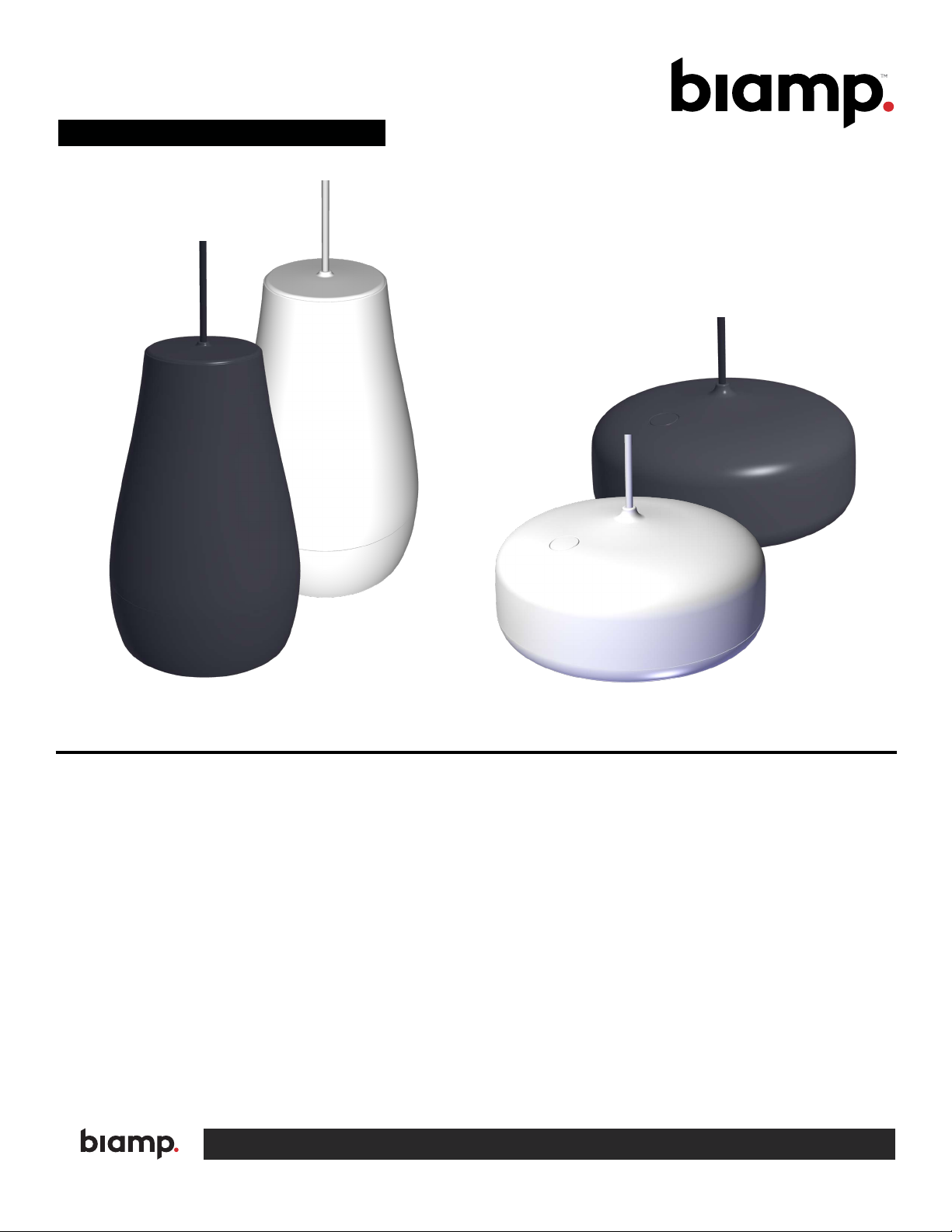
Desono P6 / P6-SM
Installation & Operation Guide
P6-SM
P6
PRODUCT DESCRIPTION
Desono™ P6 and P6-SM are two-way passive coaxial
loudspeakers intended for full range music reproduction
in distributed audio applications. They deliver high
intelligibility coupled with a wide coverage area, allowing
system designers to use fewer speakers while maintaining
acceptable levels of speech intelligibility.
There are two different styles (models) of Desono pendants.
Designed with the installer in mind, the pendants come preterminated with Magic Cable, a composite cable comprised
of two aircraft cables, two conductors jacketed separately,
and integrated ripcords that allow the installer to easily slice
through the cable jackets.
FEATURES
• Two stylish designs
• 90° conical coverage
• Magic Cable is pre-terminated inside the pendant to
ensure no exposed connections
• 6-position tap for 70V/100V systems (60W, 30W, 15W,
7.5W, 3.75W, 1.875W) with low impedance bypass
• ETL listed to comply with UL 1480A, CE marked, and
RoHS compliant
• Covered by Biamp’s seven-year warranty
A: 9300 S.W. Gemini Drive Beaverton, OR 97008 USA W: www.biamp.com
Page 2
STANDARD INSTALLATION
The Desono pendants have integral 15' (6m) cables and can be suspended up
to 14' (4.2m) if the safety supports and wiring junction boxes are within a short
distance from the drop. Preinstallation of any cable drops will require use of bulk
"Magic Cable" and a splice kit to install the loudspeaker.
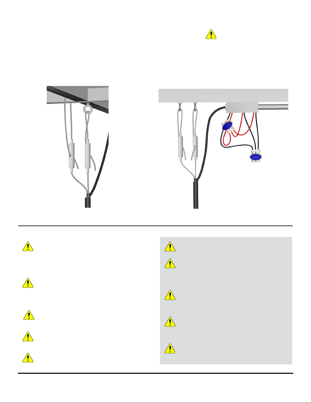
There are several methods of installation. All involve attaching the support cables
to, or around, structural elements. Some of the methods are shown below. Please
use the appropriate method for your application.
IMPORTANT: The Griplock® cable
locking devices included with the
pendants, and described in these
instructions are only rated for static indoor
installations. They should not be used to
mount the loudspeakers outdoors or other
locations subject to moisture, weather
elements or dynamic loads.
(Wire connections shown
outside the junction box to
illustrate Scotchlok connections)
Figure 1a. Support cables can loop around structural
members or through anchored hardware
RIGGING AND ELECTRICAL SAFETY
IMPORTANT: The loudspeakers described in this manual are
designed and intended to be mounted to diering building
surfaces using a variety of rigging hardware, means and
methods. Installation of loudspeakers should only be performed
by trained and qualied personnel. All electrical connections
must conform to applicable city, county, state, and national
(NEC) electrical codes.
DANGER: The Magic Cable is rated with a Working Load Limit
(WLL) of 80 lbs (36.3 kg), and the Griplocks have a WLL of 50
lbs (22.7 kg); both with a 5:1 safety margin. No single rigging
tting using the Griplock locking device should ever be
subjected to a load that is greater than 50 lbs (22.7 kg). Failure
to heed this warning could result in injury or death!
. DANGER: It is possible to experience severe electrical shock
from a power amplier. Always make sure that all power
ampliers are in the "OFF" position and unplugged from an AC
Mains supply before performing electrical work.
IMPORTANT: The Magic Cable's connection to the pendant
loudspeaker is UL listed for the purpose of suspending that
loudspeaker only. No additional objects should be attached to,
or suspended from, that cable.
IMPORTANT: Refer to the sections on installation and
connections later in this manual for additional information on
rigging and electrical safety.
Figure 1b. A typical installation with wiring connections
in a nearby junction box
IMPORTANT: Please review the safety guide
accompanying this product and these installtion
instructions prior to to installing this loudspeaker.
CAUTION: Installation of Biamp loudspeakers should only
be performed by trained and qualied personnel. It is
strongly recommended that a licensed and certied
professional structural engineer approve the mounting.
Severe injury and/or loss of life may occur if this product is
improperly installed.
DANGER: It is essential that the secondary cable be
secured to a suitable load-bearing point separate from the
primary loudspeaker mounting point, with as little slack as
possible so as not to develop undue kinetic force if the
primary mount were to fail.
IMPORTANT: Magic Cable’s strength members are
hardened stainless steel. Cutting the cables with tools not
rated for such use will damage those tools. You should use
a tool rated for cutting ACSR (Aluminum Conductor Steel
Reinforced) cables such as the Klein J2000-59.
CAUTION: The ends of the stainless steel suppor t
elements are sharp and may cause injury. Please handle
with care.
page 2 Installation and Operation Guide Desono P6, P6-SM
Page 3

Support Cable Installation
1. The outside insulation has been slit to provide access
to the interior support and audio cable elements.
Strip back that outer cover. There are rip cords in the
main cable and each of the interior elements for easy
removal of the insulation.
2. Pull the rip cords down as far as needed and cut o any
extra cable insulation (Figures 2a , 2b).
3. Insert one support cable into the bottom end of a
Griplock and push it up until the end of the wire
protrudes from the side hole (Figure 3).
4. Pull the end of the cable through the Griplock enough
to either form a loop over the structure or through
structurally anchored hardware and insert back through
the Griplock and out the remaining side hole. The wire
must extend at least 1" (25 mm) through the side hole
to ensure full gripping function.
5. Do the same to install the secondary support cable,
giving it some slack to keep it from bearing weight. The
secondary mount should be close to the primary one to
avoid any kinetic force if the primary mount should fail.
See Figure 1b for reference.
SS Aircraft
Support Cables
1/16" Stainless
steel support
cables
Figure 2a. Cable stripped
with rip cords showing
Structural
Rip Cords
signal wire
conductors
rip cords
support
(+) Conductor (–) Conductor
Rip Cord
Figure 2b. Magic Cable cross-section
Stainless Steel cables must be cut with a tool
rated for cutting ACSR cables.
Griplock
The ends of the Griplock device are spring
loaded and should be depressed to "unlock"
the cable and allow it to be adjusted
IMPORTANT: A minimum of 1" (25mm)
of cable must protrude from side holes
of the Griplock to ensure full locking
function
Figure 3. Path of the cable,
looping back through the
Griplock
Desono P6, P6-SM Installation and Operation Guide page 3
Page 4

Wiring
Scotchlok™ connectors are provided for
easy wire connections (2 per pendant). Each
connector can secure an input, output and
"pass through" wire.
1. Strip the insulation from the outside jacket around the
conductors using the rip cord.
2. Pull rip cord down and cut o extra insulation. There
is no need to strip the insulation from the individual
conductors to expose the wire if using the provided
Scotchlok connectors.
3. Fully insert positive (red) conductors into one Scotchlok
connector. See Figures 4a and 4b for correct and
incorrect insertion. Using pliers, rmly press the oval
"plunger" to secure the wires (Figures 5a, 5b). These
are single use connectors; once the plunger has been
depressed the connector must be replaced if the there
is a problem with the connection.
4. Repeat for negative (black) conductors. (Figure 6)
Note: The connections should be housed in a junction box, but
may not be subject to any force pulling on the wire or stressing the
connectors.
Conductors must
go all the way to
end of connector
(past the plunger)
Figure 4a. CORRECT wire insertion in Scotchlok connector
Conductors not fully inserted connection will fail
Figure 5a. Depress the scotchlok
plunger to fully secure the conductors
Figure 4b. INCORRECT wire insertion
in Scotchlok connector
Figure 5b. Plunger depressed;
conductors secured
Figure 6. Typical connection including a
pass through pair of conductors.
page 4 Installation and Operation Guide Desono P6, P6-SM
Page 5

Setting the Tap Switch
The Desono pendants can be utilized in both low impedance
and 70/100V systems. The default setting is low impedance,
and will need to be changed for 70/100V systems. See setting
values in the table below. Each pendant's tap switch locations
and access is also described below. To keep installation
simple, make any changes to the settings before the pendant
is installed. The knob can be rotated with a Phillips head
screwdriver or by hand.
P6
The tap switch is located under the dust cap. The pendant
is shipped with the dust cap ajar - it will be much easier to
access the switch before the cap is pressed into place. Do Not
make any changes to the tap setting while the loudspeaker is
connected to any equipment powered ON.
1. Carefully move the dust cap up the Magic Cable to
expose the switch (Figure 7).
2. Rotate the knob to the appropriate setting and align
with the arrows (Figure 8).
3. Pull the dust cap back down the cable and press into
the pendent housing until ush with the top.
P6
Figure 7. Move dust cap up the cable to access the tap
switch, and back down and pressinto place when nished
Tap Settings for both pendant models
6 Ω low impedance (default setting)
70V 60W 30W 15W 7.5W 3.75W 1.875W
100V n/a 60W 30W 15W 7.5W 3.75W
P6-SM
The tap switch is located under a removable rubber cap.
Do Not make any changes to the tap setting while the
loudspeaker is connected to any equipment powered ON.
1. A small screwdriver or ngernail will pry the cap loose.
If possible, make any changes before hanging the
pendant.
2. With the cap moved up and out of the way, rotate knob
to the appropriate setting and align with the arrows
(Figures 9a, 9b).
3. Replace the rubber cap in the pendant. It should be
ush with the pendant housing.
Figure 8. Rotate knob to select tap
setting - align desired value with arrows
P6-SM
tap switch cover
Figure 9a. LIft cap up and move out of
the way to access tap.
Figure 9b. Rotate knob to select tap setting
- align desired value with arrows
Desono P6, P6-SM Installation and Operation Guide page 5
Page 6

Typical Splice Case Applications
1. Venue has Magic Cable installed as prewired drops
2. Suspension height is longer than 14 ft (4.2m)
21
CONTACT US
Email: support@biamp.com
Web: support.biamp.com
Note: Every eort has been made to insure that the information
contained in this manual was complete and accurate when
printed. However, due to ongoing technical advances, changes or
modications may have occurred that are not covered in this manual.
The latest version is available at support.biamp.com.
Biamp Compliance: REG-00013, REG-00014
Desono P6 /P6SM Install Guide v. 10FEB2020
A: 9300 S.W. Gemini Drive Beaverton, OR 97008 USA W: www.biamp.com
 Loading...